EP3087869A1 - Hub construction for a rotatable chair - Google Patents
Hub construction for a rotatable chair Download PDFInfo
- Publication number
- EP3087869A1 EP3087869A1 EP16397512.1A EP16397512A EP3087869A1 EP 3087869 A1 EP3087869 A1 EP 3087869A1 EP 16397512 A EP16397512 A EP 16397512A EP 3087869 A1 EP3087869 A1 EP 3087869A1
- Authority
- EP
- European Patent Office
- Prior art keywords
- pin
- sleeve
- hub construction
- construction according
- upper section
- Prior art date
- Legal status (The legal status is an assumption and is not a legal conclusion. Google has not performed a legal analysis and makes no representation as to the accuracy of the status listed.)
- Granted
Links
Images

Classifications
-
- A—HUMAN NECESSITIES
- A47—FURNITURE; DOMESTIC ARTICLES OR APPLIANCES; COFFEE MILLS; SPICE MILLS; SUCTION CLEANERS IN GENERAL
- A47C—CHAIRS; SOFAS; BEDS
- A47C3/00—Chairs characterised by structural features; Chairs or stools with rotatable or vertically-adjustable seats
- A47C3/18—Chairs or stools with rotatable seat
-
- A—HUMAN NECESSITIES
- A47—FURNITURE; DOMESTIC ARTICLES OR APPLIANCES; COFFEE MILLS; SPICE MILLS; SUCTION CLEANERS IN GENERAL
- A47C—CHAIRS; SOFAS; BEDS
- A47C7/00—Parts, details, or accessories of chairs or stools
- A47C7/002—Chair or stool bases
- A47C7/004—Chair or stool bases for chairs or stools with central column, e.g. office chairs
-
- F—MECHANICAL ENGINEERING; LIGHTING; HEATING; WEAPONS; BLASTING
- F16—ENGINEERING ELEMENTS AND UNITS; GENERAL MEASURES FOR PRODUCING AND MAINTAINING EFFECTIVE FUNCTIONING OF MACHINES OR INSTALLATIONS; THERMAL INSULATION IN GENERAL
- F16B—DEVICES FOR FASTENING OR SECURING CONSTRUCTIONAL ELEMENTS OR MACHINE PARTS TOGETHER, e.g. NAILS, BOLTS, CIRCLIPS, CLAMPS, CLIPS OR WEDGES; JOINTS OR JOINTING
- F16B12/00—Jointing of furniture or the like, e.g. hidden from exterior
- F16B12/44—Leg joints; Corner joints
- F16B12/52—Metal leg connections
-
- F—MECHANICAL ENGINEERING; LIGHTING; HEATING; WEAPONS; BLASTING
- F16—ENGINEERING ELEMENTS AND UNITS; GENERAL MEASURES FOR PRODUCING AND MAINTAINING EFFECTIVE FUNCTIONING OF MACHINES OR INSTALLATIONS; THERMAL INSULATION IN GENERAL
- F16C—SHAFTS; FLEXIBLE SHAFTS; ELEMENTS OR CRANKSHAFT MECHANISMS; ROTARY BODIES OTHER THAN GEARING ELEMENTS; BEARINGS
- F16C33/00—Parts of bearings; Special methods for making bearings or parts thereof
- F16C33/02—Parts of sliding-contact bearings
- F16C33/04—Brasses; Bushes; Linings
- F16C33/06—Sliding surface mainly made of metal
- F16C33/12—Structural composition; Use of special materials or surface treatments, e.g. for rust-proofing
- F16C33/121—Use of special materials
-
- F—MECHANICAL ENGINEERING; LIGHTING; HEATING; WEAPONS; BLASTING
- F16—ENGINEERING ELEMENTS AND UNITS; GENERAL MEASURES FOR PRODUCING AND MAINTAINING EFFECTIVE FUNCTIONING OF MACHINES OR INSTALLATIONS; THERMAL INSULATION IN GENERAL
- F16C—SHAFTS; FLEXIBLE SHAFTS; ELEMENTS OR CRANKSHAFT MECHANISMS; ROTARY BODIES OTHER THAN GEARING ELEMENTS; BEARINGS
- F16C17/00—Sliding-contact bearings for exclusively rotary movement
- F16C17/10—Sliding-contact bearings for exclusively rotary movement for both radial and axial load
-
- F—MECHANICAL ENGINEERING; LIGHTING; HEATING; WEAPONS; BLASTING
- F16—ENGINEERING ELEMENTS AND UNITS; GENERAL MEASURES FOR PRODUCING AND MAINTAINING EFFECTIVE FUNCTIONING OF MACHINES OR INSTALLATIONS; THERMAL INSULATION IN GENERAL
- F16C—SHAFTS; FLEXIBLE SHAFTS; ELEMENTS OR CRANKSHAFT MECHANISMS; ROTARY BODIES OTHER THAN GEARING ELEMENTS; BEARINGS
- F16C2202/00—Solid materials defined by their properties
- F16C2202/02—Mechanical properties
- F16C2202/04—Hardness
-
- F—MECHANICAL ENGINEERING; LIGHTING; HEATING; WEAPONS; BLASTING
- F16—ENGINEERING ELEMENTS AND UNITS; GENERAL MEASURES FOR PRODUCING AND MAINTAINING EFFECTIVE FUNCTIONING OF MACHINES OR INSTALLATIONS; THERMAL INSULATION IN GENERAL
- F16C—SHAFTS; FLEXIBLE SHAFTS; ELEMENTS OR CRANKSHAFT MECHANISMS; ROTARY BODIES OTHER THAN GEARING ELEMENTS; BEARINGS
- F16C2314/00—Personal or domestic articles, e.g. household appliances such as washing machines, dryers
- F16C2314/70—Furniture
- F16C2314/73—Chairs
Definitions
- the invention relates to a hub construction for a rotatable chair, whereby an uncomplicated and robust plain bearing design is provided.
- a typical revolving chair consists of a set structure having a variety of forms, a column-type support under the seat, and a base part, which may be provided with wheels.
- the column support may comprise a spring or gas suspension structure for providing a suspension effect improving the comfort when sitting.
- the rotational movement itself is made possible by providing a torsional bearing in the column.
- a common solution is a ball or roller bearing for example under the lower end of the column, whereby the bearing is a thrust bearing carrying the total vertical load.
- the seat structure rests on a sleeve enclosing a corresponding cylindrical pin.
- the outer surface of the sleeve is conical for fitting into a corresponding conical recess in the seat.
- the common material used for the sleeve is plastic.
- patent GB 1 297 580 there is disclosed a hub construction for a rotatable chair.
- a bushing On a vertical, cylindrical pin attached to the chair's base pedestal is mounted a bushing, the outer surface of which is conical, tapering upwards.
- This cone fits a corresponding conical recess on the underside of the chair seat, and is provided with a slit in order to compensate for wear and/or tolerances in the facing parts constituting the plain bearing.
- the conical bushing is made from a durable material, preferably nylon.
- patent FI 104228 there is disclosed a hub construction for a rotatable chair, consisting of a pin enclosed by a plastic sleeve.
- the present invention is directed to a more durable construction for plain bearings in revolving chairs.
- the plain bearing parts are manufactured of metal in such a way that the bearing surface on the underlying pin is softer than that of the overlying sleeve.
- the vertical, axial load is carried by the lower edge of the sleeve, which abuts a collar section at the lower end of the pin.
- a plain bearing according to the invention may be provided with an adjustable device for obtaining higher friction and thus an increased rotational resistance.
- a horizontal bore into which is fitted at least one plug shaped body, the ends of which extend outside the mouths of the bore in the bearing surface as an adjusting screw in the upper end of the pin is tightened against the middle section of the plug-shaped body.
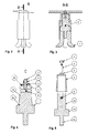
- a chair according to Fig. 1 is provided with a hub construction A according to certain embodiments of the present invention.
- the hub construction A is further shown in Fig. 2 and as a section in Fig. 3 .
- At the center of the hub is the swivel C, the lower part of which is attached to the steel pedestal structure 7.
- the swivel C is shown in greater detail in Figs. 4 and 5 . It comprises a pin 1, the cylindrical upper part of which is surrounded by a sleeve 2.
- the sleeve preferably has a conical external shape for fitting into the chair seat structure.
- Below the cylindrical upper part 1a is a collar section 1b having a diameter greater than that of the upper part.
- Below the collar section 1b is, in this embodiment, provided an additional cylindrical pin 1c for fastening the swivel in a base pedestal structure of the chair.
- At least the inner surface of sleeve 2 is made from a material harder than the pin part 1.
- the sleeve can be made of the same base material as the pin part but has been subjected to a hardening treatment.
- the sleeve may also be made of bearing bronze while the pin is of steel.
- the inner surface of the sleeve and the outer surface of the pin upper part 1a constitute bearing surfaces 9, on which conventional lubricants may be used.
- the length of the hollow in the sleeve 2 is greater than the length of the upper part la of the pin.
- the lower edge of the sleeve which preferably is flanged, thus abuts the upper surface of the collar section 1b and constitutes a bearing surface. Between the upper surface of the pin upper section 1a and the sleeve 2, there thus appears a space or distance 8.
- the vertical, axial load caused by the chair seat and someone seated there is thus carried by the lower edge of the sleeve and the collar section 1b of the pin part.
- the pin 1 is made of metal, preferably solid metal.
- the sleeve 2 is also made of metal.
- the surface on the sleeve abutting the pin part can consist of a material different from that of the rest of the sleeve, whereby it is essential that this countersurface is of a greater hardness than the pin.
- the difference in hardness between the materials of the pin vs. the sleeve can be illustrated by both being made from Fe 52 steel according to the SFS standard, and the sleeve being given a Rockwell hardness (HRC) of 50-55 by means of nitration. Depending on the material, hardening may be used to achieve the desired result. The difference in hardness prevents galling.
- the sleeve can also me manufactured from e.g. bearing bronze.
- the pin 1 in the figures is made as a single piece, but it may also be assembled from multiple parts, possibly having different hardnesses.
- the hub according to the invention may be provided with an adjustable friction brake, most clearly shown in Figs. 4 and 5 .
- an adjustable friction brake In the upper part 1a of the pin 1 is a horizontal bore, filled by a plug-shaped body 6, at least the central part of which can have a certain elasticity.
- the body 6 may consist of e.g. polyurethane.
- the sleeve is provided with a corresponding hole through which the upper end of the adjustment screw extends.
- the body 6 can consist of a non-elastic material and multiple parts, for example two parts of bearing bronze, whereby the lower end of the adjustment screw is conical and the parts are shifted radially outwards as the screw is tightened, whereby the ends of the parts are forced outwards through the openings in the bearing surface.
- the adjustment screw may be provided with a locking nut 4 facing a washer 3.
- the adjustment screw can have a head.
- the possible cone shape of the sleeve 2 may be in accordance with an industry standard, e.g. Morse.
- the seat structure may be fastened to the outside of the bearing sleeve 2 according to known methods, e.g. using a corresponding female part, i.e. a conical recess as shown in Fig. 3 .
Landscapes
- Engineering & Computer Science (AREA)
- General Engineering & Computer Science (AREA)
- Mechanical Engineering (AREA)
- Sliding-Contact Bearings (AREA)
- Pivots And Pivotal Connections (AREA)
Abstract
Description
- The invention relates to a hub construction for a rotatable chair, whereby an uncomplicated and robust plain bearing design is provided.
- A large amount of designs have been used for the rotational bearings in the construction of revolving chairs. A typical revolving chair consists of a set structure having a variety of forms, a column-type support under the seat, and a base part, which may be provided with wheels. The column support may comprise a spring or gas suspension structure for providing a suspension effect improving the comfort when sitting.
- The rotational movement itself is made possible by providing a torsional bearing in the column. A common solution is a ball or roller bearing for example under the lower end of the column, whereby the bearing is a thrust bearing carrying the total vertical load. There are also a number of designs having a ball bearing surrounding the column.
- In a more economical solution, the seat structure rests on a sleeve enclosing a corresponding cylindrical pin. The inner surface of the sleeve and the outer surface of the pin, as well as the lower edge of the sleeve and the corresponding counter surface, form plain bearing surfaces. The outer surface of the sleeve is conical for fitting into a corresponding conical recess in the seat. The common material used for the sleeve is plastic.
- In
patent GB 1 297 580 - In patent
US 6,619,742 there is disclosed a hub construction comprising a plain bearing having conical plastic parts. The upper bearing carries the vertical load and the lower bearing is spring loaded in order to eliminate any play. - In patent
FI 104228 - These structures comprising plain bearings are of a limited durability due to the properties of the plastic material.
- The present invention is directed to a more durable construction for plain bearings in revolving chairs. According to the invention, the plain bearing parts are manufactured of metal in such a way that the bearing surface on the underlying pin is softer than that of the overlying sleeve.
- The vertical, axial load is carried by the lower edge of the sleeve, which abuts a collar section at the lower end of the pin.
- Further, a plain bearing according to the invention may be provided with an adjustable device for obtaining higher friction and thus an increased rotational resistance. In the upper part of the pin is arranged a horizontal bore, into which is fitted at least one plug shaped body, the ends of which extend outside the mouths of the bore in the bearing surface as an adjusting screw in the upper end of the pin is tightened against the middle section of the plug-shaped body.
- The invention is described in further detail in the following with reference to the appended drawings, in which
-
Fig. 1 shows an example of a rotatable chair having a hub construction according to the invention, -
Fig. 2 shows the hub construction as indicated by A inFig. 1 , -
Fig. 3 shows a section in plane B-B of the hub construction inFig. 2 , -
Fig. 4 shows the central parts C in the hub construction according toFig. 3 , -
Fig. 5 shows the parts ofFig. 4 separated and rotated 90 degrees around their vertical axis. - A chair according to
Fig. 1 is provided with a hub construction A according to certain embodiments of the present invention. The hub construction A is further shown inFig. 2 and as a section inFig. 3 . At the center of the hub is the swivel C, the lower part of which is attached to thesteel pedestal structure 7. - The swivel C is shown in greater detail in
Figs. 4 and 5 . It comprises apin 1, the cylindrical upper part of which is surrounded by asleeve 2. The sleeve preferably has a conical external shape for fitting into the chair seat structure. Below the cylindrical upper part 1a is acollar section 1b having a diameter greater than that of the upper part. Below thecollar section 1b is, in this embodiment, provided an additionalcylindrical pin 1c for fastening the swivel in a base pedestal structure of the chair. - At least the inner surface of
sleeve 2 is made from a material harder than thepin part 1. For example, the sleeve can be made of the same base material as the pin part but has been subjected to a hardening treatment. The sleeve may also be made of bearing bronze while the pin is of steel. The inner surface of the sleeve and the outer surface of the pin upper part 1a constitute bearingsurfaces 9, on which conventional lubricants may be used. - The length of the hollow in the
sleeve 2 is greater than the length of the upper part la of the pin. The lower edge of the sleeve, which preferably is flanged, thus abuts the upper surface of thecollar section 1b and constitutes a bearing surface. Between the upper surface of the pin upper section 1a and thesleeve 2, there thus appears a space ordistance 8. The vertical, axial load caused by the chair seat and someone seated there is thus carried by the lower edge of the sleeve and thecollar section 1b of the pin part. - The
pin 1 is made of metal, preferably solid metal. Thesleeve 2 is also made of metal. The surface on the sleeve abutting the pin part can consist of a material different from that of the rest of the sleeve, whereby it is essential that this countersurface is of a greater hardness than the pin. - The difference in hardness between the materials of the pin vs. the sleeve can be illustrated by both being made from Fe 52 steel according to the SFS standard, and the sleeve being given a Rockwell hardness (HRC) of 50-55 by means of nitration. Depending on the material, hardening may be used to achieve the desired result. The difference in hardness prevents galling. The sleeve can also me manufactured from e.g. bearing bronze.
- The
pin 1 in the figures is made as a single piece, but it may also be assembled from multiple parts, possibly having different hardnesses. - For controlling the friction between the movable parts and thus the rotational resistance in the chair hub, the hub according to the invention may be provided with an adjustable friction brake, most clearly shown in
Figs. 4 and 5 . In the upper part 1a of thepin 1 is a horizontal bore, filled by a plug-shaped body 6, at least the central part of which can have a certain elasticity. Thebody 6 may consist of e.g. polyurethane. - From the top of the
pin 1, along its vertical central axis, extends a threaded bore opening into the horizontal bore. Into this threaded bore is screwed anadjustment screw 5, the head of which is provided with a socket for receiving a tool, e.g. a hex key, a torx key or a similar screwdriver or the like. - The sleeve is provided with a corresponding hole through which the upper end of the adjustment screw extends.
- As the adjustment screw is tightened against an elastic, plug
shaped body 6, the latter is deformed and its ends are to some extent forced out of the mouths of the horizontal bore in the cylindrical surface of the upper section of the pin part. This causes increased friction between the plain bearing surface of the sleeve and the ends of the plug shaped body, and increased resistance to rotation. - The
body 6 can consist of a non-elastic material and multiple parts, for example two parts of bearing bronze, whereby the lower end of the adjustment screw is conical and the parts are shifted radially outwards as the screw is tightened, whereby the ends of the parts are forced outwards through the openings in the bearing surface. - The adjustment screw may be provided with a locking
nut 4 facing awasher 3. In the alternative, the adjustment screw can have a head. - The possible cone shape of the
sleeve 2 may be in accordance with an industry standard, e.g. Morse. The seat structure may be fastened to the outside of thebearing sleeve 2 according to known methods, e.g. using a corresponding female part, i.e. a conical recess as shown inFig. 3 .
Claims (8)
- A bub construction for a rotatable chair, comprising a metal pin (1) having an upper section (1a) and a corresponding sleeve (2) enclosing the upper section (1a) of the pin, characterized in that the sleeve is made of metal so that at least the inner surface of the sleeve has a hardness that is greater than that of the pin.
- The hub construction according to claim 1, characterized in that the upper section (1a) of the pin comprises a horizontal bore into which has been inserted a plug-shaped body (6) consisting of one or several parts.
- The hub construction according to claim 2, characterized in that it comprises in the upper section of the pin, a vertical, central and threaded hole opening into the horizontal bore, the hole being adapted for receiving an adjustment screw (5), the end of which abuts the plug-shaped body (6).
- The hub construction according to claim 3, characterized in that the body (6) consists of a single piece of a flexible material.
- The hub construction according to claim 3, characterized in that the body (6) consists of several parts of a non-elastic material.
- The hub construction according to claim 3, characterized in that the adjustment screw (5) is provided with a locking nut (4) or a screw head.
- The hub construction according to claim 1, characterized in that it comprises, below the upper section (1a) of the pin, a cylindrical section (1b), whose upper surface the lower surface of the sleeve (2) abuts.
- The hub construction according to claim 7, characterized in the length of the hollow in the sleeve (2) being larger than the length of the upper section (1a) of the pin.
Priority Applications (1)
| Application Number | Priority Date | Filing Date | Title |
|---|---|---|---|
| PL16397512T PL3087869T3 (en) | 2015-04-30 | 2016-04-29 | Hub construction for a rotatable chair |
Applications Claiming Priority (1)
| Application Number | Priority Date | Filing Date | Title |
|---|---|---|---|
| FI20155320A FI126172B (en) | 2015-04-30 | 2015-04-30 | Hub construction for a rotatable chair |
Publications (2)
| Publication Number | Publication Date |
|---|---|
| EP3087869A1 true EP3087869A1 (en) | 2016-11-02 |
| EP3087869B1 EP3087869B1 (en) | 2018-08-01 |
Family
ID=56068816
Family Applications (1)
| Application Number | Title | Priority Date | Filing Date |
|---|---|---|---|
| EP16397512.1A Active EP3087869B1 (en) | 2015-04-30 | 2016-04-29 | Hub construction for a rotatable chair |
Country Status (7)
| Country | Link |
|---|---|
| US (1) | US10299598B2 (en) |
| EP (1) | EP3087869B1 (en) |
| CN (1) | CN106175217B (en) |
| DK (1) | DK3087869T3 (en) |
| ES (1) | ES2691538T3 (en) |
| FI (1) | FI126172B (en) |
| PL (1) | PL3087869T3 (en) |
Cited By (1)
| Publication number | Priority date | Publication date | Assignee | Title |
|---|---|---|---|---|
| DE102022201954A1 (en) | 2022-02-25 | 2023-08-31 | BSH Hausgeräte GmbH | Process, computer program product and dishwasher |
Families Citing this family (2)
| Publication number | Priority date | Publication date | Assignee | Title |
|---|---|---|---|---|
| US11533999B2 (en) * | 2020-07-30 | 2022-12-27 | B&Z Productions, LLC | Seat plate gas cylinder quick-release device |
| CN112043102B (en) * | 2020-09-07 | 2022-02-18 | 星威国际家居股份有限公司 | Quick-dismantling high-support-stability chair |
Citations (2)
| Publication number | Priority date | Publication date | Assignee | Title |
|---|---|---|---|---|
| US113606A (en) * | 1871-04-11 | Improvement in pivots for seats | ||
| US1766486A (en) * | 1928-02-27 | 1930-06-24 | Collier Keyworth Company | Chair iron |
Family Cites Families (18)
| Publication number | Priority date | Publication date | Assignee | Title |
|---|---|---|---|---|
| US2704234A (en) * | 1952-12-19 | 1955-03-15 | Glacier Co Ltd | Plain bearings |
| GB1297580A (en) * | 1970-12-15 | 1972-11-22 | ||
| SE396542B (en) * | 1976-02-06 | 1977-09-26 | Kalmar Lens Landsting | DEVICE AT THE MOBELUNDERDERNED INTENDED SO-CALL GUNGER UNIT |
| GB1502686A (en) | 1976-04-01 | 1978-03-01 | Pledge Office Chairs | Swivel chairs |
| DE2618542A1 (en) | 1976-04-28 | 1977-11-10 | Horst Walter Pollehn | Combined axial and radial shaft bearing - has stepped holes with tapered thrust face and slightly tapered portion on small dia. shaft |
| US4848934A (en) * | 1985-01-11 | 1989-07-18 | The Boeing Company | Lightweight high performance titanium sliding contact bearing |
| DE8812608U1 (en) * | 1988-10-07 | 1988-11-17 | Frenco Verzahnungslehren GmbH, 8503 Altdorf | Expansion mandrel |
| JPH03158445A (en) * | 1989-11-16 | 1991-07-08 | Mitsubishi Materials Corp | Valve seat made of fe-base sintered alloy excellent in wear resistance |
| DE4035614A1 (en) * | 1990-11-09 | 1992-05-14 | Friedrichsfeld Ag | Ball and socket joint connection - has ball and pin with space between, with interfitting conical outer and inner surfaces |
| FI104228B (en) | 1995-03-10 | 1999-12-15 | Ortus Ab Oy | Connection between foot and seat in a rotatable chair |
| JP3055804U (en) * | 1998-07-13 | 1999-01-29 | 星野楽器株式会社 | Drum chair support structure |
| CN2426034Y (en) * | 2000-05-18 | 2001-04-04 | 中国科学院物理研究所 | Adjustable vibration-damper |
| JP2002005158A (en) * | 2000-06-19 | 2002-01-09 | Minebea Co Ltd | Bearing device |
| GB2412701B (en) * | 2004-03-31 | 2006-03-22 | Minebea Co Ltd | A metal-to-metal spherical bearing |
| CN200981162Y (en) * | 2006-08-22 | 2007-11-28 | 南通纵横国际股份有限公司 | Elliptical hole inner-expanding centering device |
| US8007420B2 (en) * | 2009-01-20 | 2011-08-30 | Mullin Peter | Portable exercise device and system including same |
| CN104552478A (en) * | 2014-12-22 | 2015-04-29 | 重庆明沐家具有限公司 | Positioning device for wood board drilling |
| CN207950109U (en) * | 2017-06-28 | 2018-10-12 | 泰州市人民医院 | multifunctional chest chair |
-
2015
- 2015-04-30 FI FI20155320A patent/FI126172B/en active IP Right Grant
-
2016
- 2016-04-29 US US15/141,862 patent/US10299598B2/en active Active
- 2016-04-29 PL PL16397512T patent/PL3087869T3/en unknown
- 2016-04-29 EP EP16397512.1A patent/EP3087869B1/en active Active
- 2016-04-29 DK DK16397512.1T patent/DK3087869T3/en active
- 2016-04-29 ES ES16397512.1T patent/ES2691538T3/en active Active
- 2016-05-03 CN CN201610490967.1A patent/CN106175217B/en active Active
Patent Citations (2)
| Publication number | Priority date | Publication date | Assignee | Title |
|---|---|---|---|---|
| US113606A (en) * | 1871-04-11 | Improvement in pivots for seats | ||
| US1766486A (en) * | 1928-02-27 | 1930-06-24 | Collier Keyworth Company | Chair iron |
Cited By (3)
| Publication number | Priority date | Publication date | Assignee | Title |
|---|---|---|---|---|
| DE102022201954A1 (en) | 2022-02-25 | 2023-08-31 | BSH Hausgeräte GmbH | Process, computer program product and dishwasher |
| WO2023160844A1 (en) | 2022-02-25 | 2023-08-31 | BSH Hausgeräte GmbH | Method, computer program product, and dishwasher |
| EP4566506A2 (en) | 2022-02-25 | 2025-06-11 | BSH Hausgeräte GmbH | Method, computer program product and dishwasher |
Also Published As
| Publication number | Publication date |
|---|---|
| ES2691538T3 (en) | 2018-11-27 |
| US10299598B2 (en) | 2019-05-28 |
| US20160316913A1 (en) | 2016-11-03 |
| FI126172B (en) | 2016-07-29 |
| CN106175217B (en) | 2021-02-02 |
| CN106175217A (en) | 2016-12-07 |
| DK3087869T3 (en) | 2018-10-29 |
| FI20155320A7 (en) | 2016-07-29 |
| EP3087869B1 (en) | 2018-08-01 |
| PL3087869T3 (en) | 2019-02-28 |
Similar Documents
| Publication | Publication Date | Title |
|---|---|---|
| US4899969A (en) | Lockable elevating mechanism for the continuous adjustment of furniture and guide sleeve for such an elevating mechanism | |
| US8075056B2 (en) | Support element for seating furniture | |
| EP3087869B1 (en) | Hub construction for a rotatable chair | |
| DE4244657C2 (en) | Active dynamic seat device | |
| DE10338549A1 (en) | swing chair | |
| EP2908697B1 (en) | Seating having a pendulum column and safety device | |
| US7597295B2 (en) | Furniture stabilizer | |
| DE2623819B1 (en) | Vibration damper with adjusting device for machines | |
| US3391893A (en) | Thrust bearing for a swivel chair | |
| DE202008017646U1 (en) | chair foot | |
| DE102014000386A1 (en) | Movable seat bearing | |
| US1059313A (en) | Step-bearing for machinery. | |
| HK1231707A1 (en) | Hub construction for a rotatable chair | |
| HK1231707A (en) | Hub construction for a rotatable chair | |
| CH698900A2 (en) | Device for connecting a seat with a foothold. | |
| HK1231707B (en) | Hub construction for a rotatable chair | |
| EP2459470A1 (en) | Roller, particularly standing roller for a mail distribution system | |
| DE102010047323B4 (en) | seat storage | |
| DE202007011750U1 (en) | Pendulum stool | |
| CA2005701C (en) | Chair height adjustment mechanism | |
| DE202006013748U1 (en) | Stool comprises base and seat which is supported above it by ball which fits into curved recesses in them whose radius decreases toward their outer edges | |
| US888633A (en) | Spindle-bearing. | |
| EP1946675B1 (en) | Pendulum device | |
| WO2011114286A1 (en) | Movement device for an element of furniture | |
| US465986A (en) | Furniture-caster |
Legal Events
| Date | Code | Title | Description |
|---|---|---|---|
| PUAI | Public reference made under article 153(3) epc to a published international application that has entered the european phase |
Free format text: ORIGINAL CODE: 0009012 |
|
| AK | Designated contracting states |
Kind code of ref document: A1 Designated state(s): AL AT BE BG CH CY CZ DE DK EE ES FI FR GB GR HR HU IE IS IT LI LT LU LV MC MK MT NL NO PL PT RO RS SE SI SK SM TR |
|
| AX | Request for extension of the european patent |
Extension state: BA ME |
|
| RAP1 | Party data changed (applicant data changed or rights of an application transferred) |
Owner name: AF SOLUTIONS AB OY |
|
| RIN1 | Information on inventor provided before grant (corrected) |
Inventor name: KJELLMAN, FREDRIK |
|
| STAA | Information on the status of an ep patent application or granted ep patent |
Free format text: STATUS: REQUEST FOR EXAMINATION WAS MADE |
|
| 17P | Request for examination filed |
Effective date: 20170421 |
|
| RBV | Designated contracting states (corrected) |
Designated state(s): AL AT BE BG CH CY CZ DE DK EE ES FI FR GB GR HR HU IE IS IT LI LT LU LV MC MK MT NL NO PL PT RO RS SE SI SK SM TR |
|
| STAA | Information on the status of an ep patent application or granted ep patent |
Free format text: STATUS: EXAMINATION IS IN PROGRESS |
|
| 17Q | First examination report despatched |
Effective date: 20171121 |
|
| GRAP | Despatch of communication of intention to grant a patent |
Free format text: ORIGINAL CODE: EPIDOSNIGR1 |
|
| STAA | Information on the status of an ep patent application or granted ep patent |
Free format text: STATUS: GRANT OF PATENT IS INTENDED |
|
| INTG | Intention to grant announced |
Effective date: 20180412 |
|
| RIN1 | Information on inventor provided before grant (corrected) |
Inventor name: KJELLMAN, FREDRIK |
|
| GRAS | Grant fee paid |
Free format text: ORIGINAL CODE: EPIDOSNIGR3 |
|
| GRAA | (expected) grant |
Free format text: ORIGINAL CODE: 0009210 |
|
| STAA | Information on the status of an ep patent application or granted ep patent |
Free format text: STATUS: THE PATENT HAS BEEN GRANTED |
|
| RAP1 | Party data changed (applicant data changed or rights of an application transferred) |
Owner name: AF SOLUTIONS AB OY |
|
| AK | Designated contracting states |
Kind code of ref document: B1 Designated state(s): AL AT BE BG CH CY CZ DE DK EE ES FI FR GB GR HR HU IE IS IT LI LT LU LV MC MK MT NL NO PL PT RO RS SE SI SK SM TR |
|
| REG | Reference to a national code |
Ref country code: GB Ref legal event code: FG4D |
|
| REG | Reference to a national code |
Ref country code: CH Ref legal event code: EP Ref country code: AT Ref legal event code: REF Ref document number: 1023296 Country of ref document: AT Kind code of ref document: T Effective date: 20180815 |
|
| REG | Reference to a national code |
Ref country code: IE Ref legal event code: FG4D |
|
| REG | Reference to a national code |
Ref country code: DE Ref legal event code: R096 Ref document number: 602016004554 Country of ref document: DE |
|
| REG | Reference to a national code |
Ref country code: DK Ref legal event code: T3 Effective date: 20181016 |
|
| REG | Reference to a national code |
Ref country code: ES Ref legal event code: FG2A Ref document number: 2691538 Country of ref document: ES Kind code of ref document: T3 Effective date: 20181127 Ref country code: SE Ref legal event code: TRGR |
|
| REG | Reference to a national code |
Ref country code: NL Ref legal event code: MP Effective date: 20180801 |
|
| REG | Reference to a national code |
Ref country code: LT Ref legal event code: MG4D |
|
| REG | Reference to a national code |
Ref country code: AT Ref legal event code: MK05 Ref document number: 1023296 Country of ref document: AT Kind code of ref document: T Effective date: 20180801 |
|
| PG25 | Lapsed in a contracting state [announced via postgrant information from national office to epo] |
Ref country code: BG Free format text: LAPSE BECAUSE OF FAILURE TO SUBMIT A TRANSLATION OF THE DESCRIPTION OR TO PAY THE FEE WITHIN THE PRESCRIBED TIME-LIMIT Effective date: 20181101 Ref country code: NL Free format text: LAPSE BECAUSE OF FAILURE TO SUBMIT A TRANSLATION OF THE DESCRIPTION OR TO PAY THE FEE WITHIN THE PRESCRIBED TIME-LIMIT Effective date: 20180801 Ref country code: AT Free format text: LAPSE BECAUSE OF FAILURE TO SUBMIT A TRANSLATION OF THE DESCRIPTION OR TO PAY THE FEE WITHIN THE PRESCRIBED TIME-LIMIT Effective date: 20180801 Ref country code: GR Free format text: LAPSE BECAUSE OF FAILURE TO SUBMIT A TRANSLATION OF THE DESCRIPTION OR TO PAY THE FEE WITHIN THE PRESCRIBED TIME-LIMIT Effective date: 20181102 Ref country code: IS Free format text: LAPSE BECAUSE OF FAILURE TO SUBMIT A TRANSLATION OF THE DESCRIPTION OR TO PAY THE FEE WITHIN THE PRESCRIBED TIME-LIMIT Effective date: 20181201 Ref country code: RS Free format text: LAPSE BECAUSE OF FAILURE TO SUBMIT A TRANSLATION OF THE DESCRIPTION OR TO PAY THE FEE WITHIN THE PRESCRIBED TIME-LIMIT Effective date: 20180801 Ref country code: NO Free format text: LAPSE BECAUSE OF FAILURE TO SUBMIT A TRANSLATION OF THE DESCRIPTION OR TO PAY THE FEE WITHIN THE PRESCRIBED TIME-LIMIT Effective date: 20181101 Ref country code: FI Free format text: LAPSE BECAUSE OF FAILURE TO SUBMIT A TRANSLATION OF THE DESCRIPTION OR TO PAY THE FEE WITHIN THE PRESCRIBED TIME-LIMIT Effective date: 20180801 Ref country code: LT Free format text: LAPSE BECAUSE OF FAILURE TO SUBMIT A TRANSLATION OF THE DESCRIPTION OR TO PAY THE FEE WITHIN THE PRESCRIBED TIME-LIMIT Effective date: 20180801 |
|
| PG25 | Lapsed in a contracting state [announced via postgrant information from national office to epo] |
Ref country code: LV Free format text: LAPSE BECAUSE OF FAILURE TO SUBMIT A TRANSLATION OF THE DESCRIPTION OR TO PAY THE FEE WITHIN THE PRESCRIBED TIME-LIMIT Effective date: 20180801 Ref country code: AL Free format text: LAPSE BECAUSE OF FAILURE TO SUBMIT A TRANSLATION OF THE DESCRIPTION OR TO PAY THE FEE WITHIN THE PRESCRIBED TIME-LIMIT Effective date: 20180801 Ref country code: HR Free format text: LAPSE BECAUSE OF FAILURE TO SUBMIT A TRANSLATION OF THE DESCRIPTION OR TO PAY THE FEE WITHIN THE PRESCRIBED TIME-LIMIT Effective date: 20180801 |
|
| PG25 | Lapsed in a contracting state [announced via postgrant information from national office to epo] |
Ref country code: EE Free format text: LAPSE BECAUSE OF FAILURE TO SUBMIT A TRANSLATION OF THE DESCRIPTION OR TO PAY THE FEE WITHIN THE PRESCRIBED TIME-LIMIT Effective date: 20180801 Ref country code: RO Free format text: LAPSE BECAUSE OF FAILURE TO SUBMIT A TRANSLATION OF THE DESCRIPTION OR TO PAY THE FEE WITHIN THE PRESCRIBED TIME-LIMIT Effective date: 20180801 Ref country code: CZ Free format text: LAPSE BECAUSE OF FAILURE TO SUBMIT A TRANSLATION OF THE DESCRIPTION OR TO PAY THE FEE WITHIN THE PRESCRIBED TIME-LIMIT Effective date: 20180801 |
|
| REG | Reference to a national code |
Ref country code: DE Ref legal event code: R097 Ref document number: 602016004554 Country of ref document: DE |
|
| PG25 | Lapsed in a contracting state [announced via postgrant information from national office to epo] |
Ref country code: SK Free format text: LAPSE BECAUSE OF FAILURE TO SUBMIT A TRANSLATION OF THE DESCRIPTION OR TO PAY THE FEE WITHIN THE PRESCRIBED TIME-LIMIT Effective date: 20180801 Ref country code: SM Free format text: LAPSE BECAUSE OF FAILURE TO SUBMIT A TRANSLATION OF THE DESCRIPTION OR TO PAY THE FEE WITHIN THE PRESCRIBED TIME-LIMIT Effective date: 20180801 |
|
| PLBE | No opposition filed within time limit |
Free format text: ORIGINAL CODE: 0009261 |
|
| STAA | Information on the status of an ep patent application or granted ep patent |
Free format text: STATUS: NO OPPOSITION FILED WITHIN TIME LIMIT |
|
| 26N | No opposition filed |
Effective date: 20190503 |
|
| PG25 | Lapsed in a contracting state [announced via postgrant information from national office to epo] |
Ref country code: SI Free format text: LAPSE BECAUSE OF FAILURE TO SUBMIT A TRANSLATION OF THE DESCRIPTION OR TO PAY THE FEE WITHIN THE PRESCRIBED TIME-LIMIT Effective date: 20180801 |
|
| REG | Reference to a national code |
Ref country code: CH Ref legal event code: PL |
|
| REG | Reference to a national code |
Ref country code: BE Ref legal event code: MM Effective date: 20190430 |
|
| PG25 | Lapsed in a contracting state [announced via postgrant information from national office to epo] |
Ref country code: MC Free format text: LAPSE BECAUSE OF FAILURE TO SUBMIT A TRANSLATION OF THE DESCRIPTION OR TO PAY THE FEE WITHIN THE PRESCRIBED TIME-LIMIT Effective date: 20180801 Ref country code: LU Free format text: LAPSE BECAUSE OF NON-PAYMENT OF DUE FEES Effective date: 20190429 |
|
| PG25 | Lapsed in a contracting state [announced via postgrant information from national office to epo] |
Ref country code: CH Free format text: LAPSE BECAUSE OF NON-PAYMENT OF DUE FEES Effective date: 20190430 Ref country code: LI Free format text: LAPSE BECAUSE OF NON-PAYMENT OF DUE FEES Effective date: 20190430 |
|
| PG25 | Lapsed in a contracting state [announced via postgrant information from national office to epo] |
Ref country code: BE Free format text: LAPSE BECAUSE OF NON-PAYMENT OF DUE FEES Effective date: 20190430 Ref country code: FR Free format text: LAPSE BECAUSE OF NON-PAYMENT OF DUE FEES Effective date: 20190430 |
|
| PG25 | Lapsed in a contracting state [announced via postgrant information from national office to epo] |
Ref country code: TR Free format text: LAPSE BECAUSE OF FAILURE TO SUBMIT A TRANSLATION OF THE DESCRIPTION OR TO PAY THE FEE WITHIN THE PRESCRIBED TIME-LIMIT Effective date: 20180801 |
|
| PG25 | Lapsed in a contracting state [announced via postgrant information from national office to epo] |
Ref country code: IE Free format text: LAPSE BECAUSE OF NON-PAYMENT OF DUE FEES Effective date: 20190429 |
|
| PG25 | Lapsed in a contracting state [announced via postgrant information from national office to epo] |
Ref country code: PT Free format text: LAPSE BECAUSE OF FAILURE TO SUBMIT A TRANSLATION OF THE DESCRIPTION OR TO PAY THE FEE WITHIN THE PRESCRIBED TIME-LIMIT Effective date: 20181201 |
|
| PG25 | Lapsed in a contracting state [announced via postgrant information from national office to epo] |
Ref country code: CY Free format text: LAPSE BECAUSE OF FAILURE TO SUBMIT A TRANSLATION OF THE DESCRIPTION OR TO PAY THE FEE WITHIN THE PRESCRIBED TIME-LIMIT Effective date: 20180801 |
|
| PG25 | Lapsed in a contracting state [announced via postgrant information from national office to epo] |
Ref country code: MT Free format text: LAPSE BECAUSE OF FAILURE TO SUBMIT A TRANSLATION OF THE DESCRIPTION OR TO PAY THE FEE WITHIN THE PRESCRIBED TIME-LIMIT Effective date: 20180801 Ref country code: HU Free format text: LAPSE BECAUSE OF FAILURE TO SUBMIT A TRANSLATION OF THE DESCRIPTION OR TO PAY THE FEE WITHIN THE PRESCRIBED TIME-LIMIT; INVALID AB INITIO Effective date: 20160429 |
|
| PG25 | Lapsed in a contracting state [announced via postgrant information from national office to epo] |
Ref country code: MK Free format text: LAPSE BECAUSE OF FAILURE TO SUBMIT A TRANSLATION OF THE DESCRIPTION OR TO PAY THE FEE WITHIN THE PRESCRIBED TIME-LIMIT Effective date: 20180801 |
|
| PGFP | Annual fee paid to national office [announced via postgrant information from national office to epo] |
Ref country code: PL Payment date: 20250418 Year of fee payment: 10 Ref country code: DE Payment date: 20250422 Year of fee payment: 10 |
|
| PGFP | Annual fee paid to national office [announced via postgrant information from national office to epo] |
Ref country code: ES Payment date: 20250529 Year of fee payment: 10 Ref country code: GB Payment date: 20250423 Year of fee payment: 10 Ref country code: DK Payment date: 20250429 Year of fee payment: 10 |
|
| PGFP | Annual fee paid to national office [announced via postgrant information from national office to epo] |
Ref country code: IT Payment date: 20250424 Year of fee payment: 10 |
|
| PGFP | Annual fee paid to national office [announced via postgrant information from national office to epo] |
Ref country code: SE Payment date: 20250429 Year of fee payment: 10 |