EP3088782A1 - Hydraulisches steuerventil in schieberbauweise und mobilhydraulik mit entsprechendem steuerventil - Google Patents
Hydraulisches steuerventil in schieberbauweise und mobilhydraulik mit entsprechendem steuerventil Download PDFInfo
- Publication number
- EP3088782A1 EP3088782A1 EP15165659.2A EP15165659A EP3088782A1 EP 3088782 A1 EP3088782 A1 EP 3088782A1 EP 15165659 A EP15165659 A EP 15165659A EP 3088782 A1 EP3088782 A1 EP 3088782A1
- Authority
- EP
- European Patent Office
- Prior art keywords
- control valve
- stroke
- hydraulic
- operating mode
- shaft
- Prior art date
- Legal status (The legal status is an assumption and is not a legal conclusion. Google has not performed a legal analysis and makes no representation as to the accuracy of the status listed.)
- Granted
Links
Images


Classifications
-
- F—MECHANICAL ENGINEERING; LIGHTING; HEATING; WEAPONS; BLASTING
- F15—FLUID-PRESSURE ACTUATORS; HYDRAULICS OR PNEUMATICS IN GENERAL
- F15B—SYSTEMS ACTING BY MEANS OF FLUIDS IN GENERAL; FLUID-PRESSURE ACTUATORS, e.g. SERVOMOTORS; DETAILS OF FLUID-PRESSURE SYSTEMS, NOT OTHERWISE PROVIDED FOR
- F15B13/00—Details of servomotor systems ; Valves for servomotor systems
- F15B13/02—Fluid distribution or supply devices characterised by their adaptation to the control of servomotors
- F15B13/04—Fluid distribution or supply devices characterised by their adaptation to the control of servomotors for use with a single servomotor
-
- E—FIXED CONSTRUCTIONS
- E04—BUILDING
- E04G—SCAFFOLDING; FORMS; SHUTTERING; BUILDING IMPLEMENTS OR AIDS, OR THEIR USE; HANDLING BUILDING MATERIALS ON THE SITE; REPAIRING, BREAKING-UP OR OTHER WORK ON EXISTING BUILDINGS
- E04G21/00—Preparing, conveying, or working-up building materials or building elements in situ; Other devices or measures for constructional work
- E04G21/02—Conveying or working-up concrete or similar masses able to be heaped or cast
- E04G21/04—Devices for both conveying and distributing
- E04G21/0418—Devices for both conveying and distributing with distribution hose
- E04G21/0436—Devices for both conveying and distributing with distribution hose on a mobile support, e.g. truck
-
- E—FIXED CONSTRUCTIONS
- E04—BUILDING
- E04G—SCAFFOLDING; FORMS; SHUTTERING; BUILDING IMPLEMENTS OR AIDS, OR THEIR USE; HANDLING BUILDING MATERIALS ON THE SITE; REPAIRING, BREAKING-UP OR OTHER WORK ON EXISTING BUILDINGS
- E04G21/00—Preparing, conveying, or working-up building materials or building elements in situ; Other devices or measures for constructional work
- E04G21/02—Conveying or working-up concrete or similar masses able to be heaped or cast
- E04G21/04—Devices for both conveying and distributing
- E04G21/0418—Devices for both conveying and distributing with distribution hose
- E04G21/0445—Devices for both conveying and distributing with distribution hose with booms
- E04G21/0463—Devices for both conveying and distributing with distribution hose with booms with boom control mechanisms, e.g. to automate concrete distribution
-
- F—MECHANICAL ENGINEERING; LIGHTING; HEATING; WEAPONS; BLASTING
- F16—ENGINEERING ELEMENTS AND UNITS; GENERAL MEASURES FOR PRODUCING AND MAINTAINING EFFECTIVE FUNCTIONING OF MACHINES OR INSTALLATIONS; THERMAL INSULATION IN GENERAL
- F16K—VALVES; TAPS; COCKS; ACTUATING-FLOATS; DEVICES FOR VENTING OR AERATING
- F16K11/00—Multiple-way valves, e.g. mixing valves; Pipe fittings incorporating such valves
- F16K11/02—Multiple-way valves, e.g. mixing valves; Pipe fittings incorporating such valves with all movable sealing faces moving as one unit
- F16K11/06—Multiple-way valves, e.g. mixing valves; Pipe fittings incorporating such valves with all movable sealing faces moving as one unit comprising only sliding valves, i.e. sliding closure elements
- F16K11/065—Multiple-way valves, e.g. mixing valves; Pipe fittings incorporating such valves with all movable sealing faces moving as one unit comprising only sliding valves, i.e. sliding closure elements with linearly sliding closure members
- F16K11/07—Multiple-way valves, e.g. mixing valves; Pipe fittings incorporating such valves with all movable sealing faces moving as one unit comprising only sliding valves, i.e. sliding closure elements with linearly sliding closure members with cylindrical slides
-
- F—MECHANICAL ENGINEERING; LIGHTING; HEATING; WEAPONS; BLASTING
- F16—ENGINEERING ELEMENTS AND UNITS; GENERAL MEASURES FOR PRODUCING AND MAINTAINING EFFECTIVE FUNCTIONING OF MACHINES OR INSTALLATIONS; THERMAL INSULATION IN GENERAL
- F16K—VALVES; TAPS; COCKS; ACTUATING-FLOATS; DEVICES FOR VENTING OR AERATING
- F16K3/00—Gate valves or sliding valves, i.e. cut-off apparatus with closing members having a sliding movement along the seat for opening and closing
- F16K3/22—Gate valves or sliding valves, i.e. cut-off apparatus with closing members having a sliding movement along the seat for opening and closing with sealing faces shaped as surfaces of solids of revolution
- F16K3/24—Gate valves or sliding valves, i.e. cut-off apparatus with closing members having a sliding movement along the seat for opening and closing with sealing faces shaped as surfaces of solids of revolution with cylindrical valve members
-
- F—MECHANICAL ENGINEERING; LIGHTING; HEATING; WEAPONS; BLASTING
- F16—ENGINEERING ELEMENTS AND UNITS; GENERAL MEASURES FOR PRODUCING AND MAINTAINING EFFECTIVE FUNCTIONING OF MACHINES OR INSTALLATIONS; THERMAL INSULATION IN GENERAL
- F16K—VALVES; TAPS; COCKS; ACTUATING-FLOATS; DEVICES FOR VENTING OR AERATING
- F16K3/00—Gate valves or sliding valves, i.e. cut-off apparatus with closing members having a sliding movement along the seat for opening and closing
- F16K3/30—Details
- F16K3/32—Means for additional adjustment of the rate of flow
-
- F—MECHANICAL ENGINEERING; LIGHTING; HEATING; WEAPONS; BLASTING
- F16—ENGINEERING ELEMENTS AND UNITS; GENERAL MEASURES FOR PRODUCING AND MAINTAINING EFFECTIVE FUNCTIONING OF MACHINES OR INSTALLATIONS; THERMAL INSULATION IN GENERAL
- F16K—VALVES; TAPS; COCKS; ACTUATING-FLOATS; DEVICES FOR VENTING OR AERATING
- F16K31/00—Actuating devices; Operating means; Releasing devices
- F16K31/12—Actuating devices; Operating means; Releasing devices actuated by fluid
- F16K31/14—Actuating devices; Operating means; Releasing devices actuated by fluid for mounting on, or in combination with, hand-actuated valves
-
- F—MECHANICAL ENGINEERING; LIGHTING; HEATING; WEAPONS; BLASTING
- F16—ENGINEERING ELEMENTS AND UNITS; GENERAL MEASURES FOR PRODUCING AND MAINTAINING EFFECTIVE FUNCTIONING OF MACHINES OR INSTALLATIONS; THERMAL INSULATION IN GENERAL
- F16K—VALVES; TAPS; COCKS; ACTUATING-FLOATS; DEVICES FOR VENTING OR AERATING
- F16K35/00—Means to prevent accidental or unauthorised actuation
- F16K35/04—Means to prevent accidental or unauthorised actuation yieldingly resisting the actuation
-
- F—MECHANICAL ENGINEERING; LIGHTING; HEATING; WEAPONS; BLASTING
- F15—FLUID-PRESSURE ACTUATORS; HYDRAULICS OR PNEUMATICS IN GENERAL
- F15B—SYSTEMS ACTING BY MEANS OF FLUIDS IN GENERAL; FLUID-PRESSURE ACTUATORS, e.g. SERVOMOTORS; DETAILS OF FLUID-PRESSURE SYSTEMS, NOT OTHERWISE PROVIDED FOR
- F15B2211/00—Circuits for servomotor systems
- F15B2211/40—Flow control
- F15B2211/42—Flow control characterised by the type of actuation
- F15B2211/421—Flow control characterised by the type of actuation mechanically
- F15B2211/423—Flow control characterised by the type of actuation mechanically manually, e.g. by using a lever or pedal
-
- F—MECHANICAL ENGINEERING; LIGHTING; HEATING; WEAPONS; BLASTING
- F15—FLUID-PRESSURE ACTUATORS; HYDRAULICS OR PNEUMATICS IN GENERAL
- F15B—SYSTEMS ACTING BY MEANS OF FLUIDS IN GENERAL; FLUID-PRESSURE ACTUATORS, e.g. SERVOMOTORS; DETAILS OF FLUID-PRESSURE SYSTEMS, NOT OTHERWISE PROVIDED FOR
- F15B2211/00—Circuits for servomotor systems
- F15B2211/40—Flow control
- F15B2211/42—Flow control characterised by the type of actuation
- F15B2211/426—Flow control characterised by the type of actuation electrically or electronically
-
- F—MECHANICAL ENGINEERING; LIGHTING; HEATING; WEAPONS; BLASTING
- F15—FLUID-PRESSURE ACTUATORS; HYDRAULICS OR PNEUMATICS IN GENERAL
- F15B—SYSTEMS ACTING BY MEANS OF FLUIDS IN GENERAL; FLUID-PRESSURE ACTUATORS, e.g. SERVOMOTORS; DETAILS OF FLUID-PRESSURE SYSTEMS, NOT OTHERWISE PROVIDED FOR
- F15B2211/00—Circuits for servomotor systems
- F15B2211/40—Flow control
- F15B2211/42—Flow control characterised by the type of actuation
- F15B2211/428—Flow control characterised by the type of actuation actuated by fluid pressure
-
- F—MECHANICAL ENGINEERING; LIGHTING; HEATING; WEAPONS; BLASTING
- F15—FLUID-PRESSURE ACTUATORS; HYDRAULICS OR PNEUMATICS IN GENERAL
- F15B—SYSTEMS ACTING BY MEANS OF FLUIDS IN GENERAL; FLUID-PRESSURE ACTUATORS, e.g. SERVOMOTORS; DETAILS OF FLUID-PRESSURE SYSTEMS, NOT OTHERWISE PROVIDED FOR
- F15B2211/00—Circuits for servomotor systems
- F15B2211/50—Pressure control
- F15B2211/52—Pressure control characterised by the type of actuation
- F15B2211/521—Pressure control characterised by the type of actuation mechanically
- F15B2211/523—Pressure control characterised by the type of actuation mechanically manually, e.g. by using a lever or pedal
-
- F—MECHANICAL ENGINEERING; LIGHTING; HEATING; WEAPONS; BLASTING
- F15—FLUID-PRESSURE ACTUATORS; HYDRAULICS OR PNEUMATICS IN GENERAL
- F15B—SYSTEMS ACTING BY MEANS OF FLUIDS IN GENERAL; FLUID-PRESSURE ACTUATORS, e.g. SERVOMOTORS; DETAILS OF FLUID-PRESSURE SYSTEMS, NOT OTHERWISE PROVIDED FOR
- F15B2211/00—Circuits for servomotor systems
- F15B2211/50—Pressure control
- F15B2211/52—Pressure control characterised by the type of actuation
- F15B2211/526—Pressure control characterised by the type of actuation electrically or electronically
-
- F—MECHANICAL ENGINEERING; LIGHTING; HEATING; WEAPONS; BLASTING
- F15—FLUID-PRESSURE ACTUATORS; HYDRAULICS OR PNEUMATICS IN GENERAL
- F15B—SYSTEMS ACTING BY MEANS OF FLUIDS IN GENERAL; FLUID-PRESSURE ACTUATORS, e.g. SERVOMOTORS; DETAILS OF FLUID-PRESSURE SYSTEMS, NOT OTHERWISE PROVIDED FOR
- F15B2211/00—Circuits for servomotor systems
- F15B2211/50—Pressure control
- F15B2211/52—Pressure control characterised by the type of actuation
- F15B2211/528—Pressure control characterised by the type of actuation actuated by fluid pressure
-
- F—MECHANICAL ENGINEERING; LIGHTING; HEATING; WEAPONS; BLASTING
- F15—FLUID-PRESSURE ACTUATORS; HYDRAULICS OR PNEUMATICS IN GENERAL
- F15B—SYSTEMS ACTING BY MEANS OF FLUIDS IN GENERAL; FLUID-PRESSURE ACTUATORS, e.g. SERVOMOTORS; DETAILS OF FLUID-PRESSURE SYSTEMS, NOT OTHERWISE PROVIDED FOR
- F15B2211/00—Circuits for servomotor systems
- F15B2211/80—Other types of control related to particular problems or conditions
- F15B2211/895—Manual override
Definitions
- the present invention relates generally to hydraulic control valves designed in slide construction with a spool whose stroke is adjustable in a housing along a stroke direction in at least a first operating mode and a second operating mode, and a mobile hydraulics with a corresponding control valve and a hydraulic consumer.
- Sliding valve hydraulic control valves are used to power hydraulic consumers in a variety of applications, such as e.g. Among other things, for retracting, extending and pivoting turntables or telescopic masts in aerial rescue vehicles.
- hydraulic control valves are also used i.a. Used in drives of support systems for supporting trucks.
- hydraulic control valves are usually arranged in the hydraulic power take-off before hydraulic consumers that drive turntables, telescopic masts, support systems or the like.
- the hydraulic pump may e.g. be driven by a vehicle engine of a vehicle via a power take-off. After connection of the auxiliary drive in this case, an oil flow is generated by the hydraulic pump with low volume, which is often circulated via a non-pressurized return line.
- Example the speed of the vehicle engine, and thus the speed of the coupled hydraulic pump to be increased at a control station on the vehicle, whereby the circulated oil quantity increases.
- the oil flow is then passed via the hydraulic control valve to the supports, where it flows in hydraulic cylinders of Ausschubyn or Ausschubzylindern of support beams and this extends to a predetermined support width.
- an oil stream is supplied to corresponding work cylinders for driving turntable ladders or telescopic masts.
- control valves to control extension, retraction and / or swing speeds.
- control valves are designed as a proportional directional valve, wherein a flow rate controlled by the control valve via a control edge in the control valve is or a volume flow output from the control valve is proportional to the stroke of a spool in the control valve adjustable.
- Fig. 1 shows a known hydraulic control valve S, which is designed as a proportional Wegeschieber and in the published patent application DE 44 23 583 A1 is described.
- the hydraulic control valve S according to Fig. 1 has a block-shaped housing G with a longitudinal direction L through the housing G extending housing bore in which a spool K either by a hand lever H or a proportional solenoid M or a hydraulic pilot V out of a shut-off or neutral position in which a flow through the control valve S is zero, is adjustable in at least one direction.
- a pressure connection is provided which is formed by a circular recess 4 'in the housing.
- a further circular depression (not shown) is arranged diametrically opposite the depression 4 'in the housing G, whereby an outlet connection (not shown) of the control valve S is provided.
- the depression 4 ' is connected to the diametrically opposite recess (not shown) via a groove 5' extending in the circumferential direction of the spool K.
- the groove 5 'in the circumferential direction of the spool K an interruption, in the area by the cooperation between the cylindrical peripheral surface of the spool K and a wall of the housing G, a local Gleitdichtzone is formed.
- the depth of the groove 5 'expedient ly decreases to zero for interruption.
- the stroke of the spool K in the housing G can now be adjusted by the hand lever H, the proportional solenoid M or by a hydraulic feedforward V depending on the operating mode.
- the hydraulic pilot control V in this case has a pilot control channel VK, by which a control pressure pending on the pilot control duct VK is used to control the slide piston K in the control valve S.
- the hand lever H allows a manual stroke adjustment of the spool K, wherein the hand lever H is pivotally mounted about a pivot axis SA on the housing S. By pivoting the hand lever H about the pivot axis SA, a recorded in a housing G arranged on the lever housing HG shaft W is driven, which is connected to the spool K by a not shown driver is connected.
- a stroke of the spool K in the housing G is adjusted manually proportional to the pivoting of the hand lever H.
- a stroke limitation of the spool K is predetermined by a stop element AS, which defines a range of pivot angle of the hand lever H about the pivot axis SA.
- a maximum pivot angle By specifying a maximum pivot angle by means of the stop element AS, a maximum stroke of the spool K along the longitudinal direction L is further defined in the housing G, since each stroke adjustment of the spool is transmitted via the driver (not shown) to the shaft W and a pivoting movement of the hand lever H corresponding to a rotation of the shaft W leads, which is transmitted by the driver (not shown) in a lifting movement of the spool K on the shaft W.
- a volume flow through the control valve S is set proportionally to the stroke of the spool K in the housing G, from which it follows that the maximum stroke limitation by the stop element AS as a whole sets a maximum volume flow through the control valve S.
- the maximum volumetric flow is independent of the operating mode, i. regardless of whether the stroke adjustment via the hand lever H, the proportional solenoid M or the hydraulic feedforward V occurs. Since the volume flow is still proportional to an extending, retracting or pivoting speed of the connected hydraulic consumer, it follows that a maximum speed is specified independently of the operating mode for a connected hydraulic consumer.
- a hydraulic control valve in spool design is provided with a spool whose stroke is adjustable in a housing along a stroke direction in at least a first operating mode and a second operating mode.
- the hydraulic control valve is characterized in that a first maximum stroke determined in the first operating mode differs from a maximum stroke defined in the second operating mode. Depending on the operating mode, it is thus possible for different maximum operating speeds to be predetermined in a hydraulic consumer connected downstream of the hydraulic control valve.
- a spool type hydraulic control valve is provided with a spool whose stroke is adjustable in a housing along a stroke direction in at least a first operating mode by a first drive and in a second operating mode by a second drive other than the first drive is.
- the hydraulic control valve is characterized in that an adjustment of the stroke by the first drive from the setting of the stroke by the second drive is mechanically decoupled.
- a hydraulic control valve is provided with drives for stroke adjustment, wherein the drives are mechanically decoupled and consequently the control valve downstream hydraulic consumers can be operated at different maximum speeds depending on the operating mode.
- the second maximum stroke in the control valve according to the first aspect is smaller than the first maximum stroke.
- a second operating mode with a lower operating speed can advantageously be provided at a downstream hydraulic consumer.
- the stroke in the first mode of operation of the control valve according to the first aspect or the first embodiment, is adjustable by a proportional solenoid and / or a hydraulic pilot, while in the second mode of operation the stroke is manually adjustable by a hand lever disposed on the housing.
- a stroke limitation in manual operation can be provided independently of a stroke limitation in an electrical and / or hydraulic operation.
- the first drive of the control valve according to the second aspect comprises a proportional solenoid and / or a hydraulic pilot control
- the second drive comprises a hand lever.
- the hand lever with the spool on the control valve according to the second or third embodiment is mechanically coupled. This allows the hand lever to be coupled with the spool when needed, while otherwise being mechanically decoupled from the spool.
- the spool in the control valve according to the fourth embodiment is fixedly connected via a driver with a shaft via which the stroke is adjustable by means of the hand lever in the second operating mode. Furthermore, a releasable coupling is provided between the shaft and the hand lever. This provides an advantageous implementation of the mechanical coupling between the hand lever and slide, wherein the hand lever does not necessarily have to be located in close proximity to the spool.
- the releasable coupling in the control valve according to the fifth embodiment has a recess formed in the shaft, in which the hand lever for transmitting torque to the shaft can be coupled.
- the releasable coupling in the control valve according to the sixth embodiment comprises a mechanical spring element which is biased such that the hand lever is pushed out of the recess without external force.
- the second maximum stroke in the control valve according to one of the fourth to seventh embodiments is defined by a limiting element provided on the housing, which limits the movement of the hand lever relative to the housing in accordance with the second maximum stroke. This provides a simple and advantageous stroke limitation in manual mode of operation.
- the shaft in the control valve according to one of the fourth to eighth embodiments is mounted in a housing arranged on the lever housing and the hand lever is supported by a top piece on the lever housing, wherein the top piece rotatable in the first operating mode relative to the shaft and in the second operating mode is firmly connected to the shaft.
- the attachment piece in the control valve according to the ninth embodiment is detachably connected to the shaft by a coupling element and the second maximum stroke is predetermined by a stop element arranged on the lever housing, which limits a rotational movement of the attachment piece about an axis of rotation defined by the shaft.
- a mobile hydraulics having a control valve according to the first aspect or the second aspect or a hydraulic consumer arranged downstream of the control valve, preferably a working cylinder or a hydraulic winch, wherein for the hydraulic consumer depending on the operating mode of the control valve different maximum speeds are given.
- the second operating mode corresponds to an emergency operation with an emergency speed of the hydraulic consumer defined by the second maximum lift or the second drive, that of a maximum operating speed predetermined by the first maximum lift or the first drive in the first operating mode of the hydraulic consumer is different.
- the hydraulic consumer is a mast or ladder cylinder by which a position of a mast or a ladder is adjustable.
- the present invention is based on the proposal to provide a trained in slide design hydraulic control valve with spool, such.
- B. a Proportionalwegeschieberventil whose stroke is adjustable in a housing along a stroke direction in at least a first operating mode and a second operating mode.
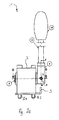
- Fig. 2a shows schematically in a cross-sectional view of a manual drive 1, on the housing of a control valve in spool design (for example, the housing G from Fig. 1 ) can be arranged.
- the manual drive 1 comprises a lever housing 2 which is arranged via screws S1, S2 on the housing (not shown) of a control valve (not shown) can be.
- a shaft 5 is received, by which a pivot axis of the manual drive 1 is determined.
- the pivot axis runs along the line BB.
- the shaft 5 is rotatably mounted in the lever housing 2 and passes through the lever housing 2 at least partially.
- a top piece 6 is further provided on an emerging from the lever housing 2 end of the shaft 5, in which the shaft 5 is at least partially inserted.
- the shaft 5 In an operating mode in which a stroke is to be set by the manual drive 1 in a control valve (not shown), the shaft 5 is fixedly coupled or engaged with the attachment piece 6.
- the shaft 5 and the attachment piece 6 In another operating mode in which a stroke adjustment by the manual drive 1 is not provided, the shaft 5 and the attachment piece 6 are rotatably arranged relative to each other.
- the attachment piece 6 as shown in FIG Fig. 2a connected via a lever rod 10 with a handle 18.
- the handle 18 and the lever rod 10 form a hand lever, as in Fig. 2a is shown.
- the hand lever may be provided without handle 18.
- the top piece 6 and the shaft 5 via a coupling element, such as a pin, a bolt, a screw or a rod, firmly connected to each other, but the solid connection can be solved by the coupling element when needed again.
- a coupling element such as a pin, a bolt, a screw or a rod
- the lever rod 10 and the attachment piece 6 are movable relative to each other, so that between the lever rod 10 and the shaft 5, a detachable connection can be made (see Fig. 2b below).
- the lever rod 10 may be fixedly attached to the top piece 6 or the lever rod 10 and the top piece 6 are integrally formed.
- the lever rod 10 is not a coupling element and the coupling element can be provided by a pin, a bolt, a screw, etc., wherein the attachment piece 6 and the shaft 5 can be connected by the coupling element in a detachable manner.
- a lateral bore 7 is provided on the attachment piece 6 into which a coupling element 8 is inserted, such as a screw, a pin Bolts or the like.
- a coupling element 8 can be brought into harmony with the shaft 5, for example by screwing in a screw or inserting a pin or bolt into the bore 7, so that the shaft 5 is detected with respect to the attachment piece 6.
- an engagement structure such as a groove or bore provided in alignment with the bore 7 on the attachment piece 6 may be provided on the shaft 5 so that when the engagement structure is in alignment with the bore 7 the coupling element 8 is brought into engagement with the engagement structure of the shaft and the shaft 5 can be detected with respect to the attachment piece 6.
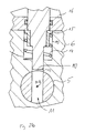
- a shaft 5 at least partially radially passing through recess, such. B. a through hole 11.
- a groove (not shown) or a blind hole (not shown) may be provided instead of the through hole 11 in the peripheral surface of the shaft 5.
- the through hole 11 or a corresponding structure may have a widened opening, so that an insertion of the lever rod 10 into the through hole 11 (or the corresponding structure) is simplified.
- this may have a cross-section that tapers radially toward the pivot axis BB.
- the through hole 11 provides over a blind hole or a groove the advantage that an engagement between the lever rod 10 and shaft 5 at two positions of the shaft 5 over a full rotation of the shaft 5 is possible.
- several blind holes or grooves can be provided in the circumferential direction of the shaft 5.
- the plurality of grooves or blind holes may e.g. be distributed uniformly along the circumferential direction of the shaft 5.
- a bore 12 is provided in the attachment piece 6, which can be brought into alignment with the shaft 5 in alignment, so that introduced into the bore 12 lever rod 10 can be inserted in aligned alignment in the through hole 11 of the shaft 5.
- the bore 12 has a continuation of a blind hole 13 having a diameter larger than a diameter of the bore 12.
- a spring 14 or other elastic biasing member is arranged to extend the lever rod 10 along one direction to bias the through hole 11 out. This can be in the blind hole 13 around the lever rod 10 a sleeve member 15 may be arranged, through which the lever rod 10 is pressed by the spring 14 from the through hole 11 out.
- the lever rod 10 can be inserted into the through hole 11 only by a force exerted on the lever rod 10 by the biasing force of the spring along a direction into the through hole 11 (in alignment with the through hole 11).
- This provides the advantage that the manual drive 1 off Fig. 2a mechanically by strokes of a spool in a control valve (for example, from the spool K in the control valve S off Fig. 1 when the mechanical drive 1 instead of the hand lever H with lever housing HG in Fig. 1 is provided) and only by an active actuation of the manual drive 1, that is, an active insertion of the lever rod 10 in the through hole 11 against the bias by the spring 14, can be switched to a manual drive 1 corresponding operating mode of the control valve.
- a force acting on the lever rod 10 biasing force can be achieved by the spring 14, which presses the lever rod 10 in the through hole 11, so that only by applying a bias of the spring 14 exceeding force, the coupling between the lever rod 10 and the shaft 5 is released.
- the sleeve member 15 is arranged in the blind hole, that the spring is supported against the plate 16 and the sleeve member 15 is pressed by the biasing force of the spring 14 to the bottom of the blind hole 13.
- a corresponding prestressing structure can be formed outside of the attachment piece between the attachment piece 6 and the lever rod 10, as is known, for example, for ballpoint pen refills in ballpoint pens.
- a flange-like protrusion may be provided on the lever rod 10 on the top piece 6, to which a biasing force is exerted by means of a arranged outside of the top piece 6 spring, depending on the arrangement of the spring with respect to the flange and the top piece 6, optionally with a outside attached to the top piece 6 sleeve (not shown), a bias voltage which is directed into the through hole 11 or directed out of the through hole 11 out.
- Fig. 2a along with Fig. 2c will be described below a limitation of the maximum stroke in the manual drive 1, which is provided by a Maximalhubbegrenzung in an alternative to the manual drive 1 mode of operation.
- Fig. 2a shows a stop element 3, corresponding to the stop element AF Fig. 1 that limits a pivot angle range of the lever rod 10 about the pivot axis BB around.
- a desired pivoting angle range of the lever rod 10 about the pivot axis BB can be specified.
- FIG. 2a can be provided resilient stop surfaces (not shown), which characterize a desired pivoting angle range, for example, by an increasing spring force on the lever rod 10, as soon as it is swung outside a predetermined pivoting angle range, and / or support the lever rod 10 in a desired orientation relative to the lever housing 2 ,
- Fig. 2c schematically shows a cross-sectional view along the pivot axis BB in Fig. 2a in supervision dar.
- the shaft 5 extends along the pivot axis BB through the piston housing 2.
- a driver 17 is mounted, which is accommodated in a recess 18 in the piston housing 2.
- the recess 18 continues through the piston housing 2 into a housing (not shown) of a control valve (not shown) arranged below the piston housing 2, the driver 17 being articulated to a slide piston (not shown) of the control valve (not shown). ie, that the driver 17 (see. Fig.
- Fig. 2a to 2c hydraulic control valves with a first operating mode and at least one second operating mode are provided, wherein the stroke of a spool in the control valve in the second operating mode by a hydraulic and / or electric drive (see M and / or V in Fig. 1 ) can be adjusted while the stroke of the spool in the control valve in the first operating mode by a manual drive (see manual drive 1 in Fig. 2a ) can be adjusted.
- the manual drive 1 (see. Fig. 2a ) is mechanically from the electric and / or hydraulic drive (see M and / or V in Fig. 1 ) decoupled.
- a stroke limitation in the first operating mode which differs from a stroke limitation in the second operating mode.
- a corresponding maximum lift can be preset, which differs from the maximum lift of the other operating mode or modes.
- a mobile hydraulics having a control valve according to the previously described illustrative embodiments, wherein the control valve is provided in the supply line in front of a hydraulic consumer, such as a water heater.
- a hydraulic consumer such as a water heater.
- a working cylinder or a hydraulic winch or the like is arranged.
- hydraulic consumers may be employed by power cylinders to operate aerial ladders, telescoping masts, support systems, outriggers, etc. of aerial rescue vehicles, cranes, power machines, and the like.
- an illustrative hydraulic consumer may represent a mast or ladder cylinder through which a position of a mast or ladder or pivot position of a mast or ladder may be approached.
- the second mode of operation may designate normal operation.
- a second maximum stroke can be predetermined by a second stroke limitation in the control valve, for example by suitable measures in the hydraulic and / or electrical pilot control, the geometry of the valve housing, etc.
- the first operating mode can represent an emergency operation in which, for example, in case of failure the electrical and / or hydraulic Pilot control, a controlled by the control valve hydraulic consumer is controlled.
- a different from the second maximum stroke first maximum stroke can be specified, for example by suitable stop elements, as in terms Fig. 2a . 2c is described above, so that in emergency operation, for example, a defined maximum emergency speed can be driven, which differ from predetermined maximum operating speeds in normal operation, in particular less than the predetermined maximum (s) speed (s) in normal operation.
- mobile hydraulic systems may e.g. Fire ladders, loading cranes, concrete pumps (where electrically controlled may be driven faster than in emergency mode), etc. include.
- a manual drive with hand lever and shaft is described above, which is connected to a spool of a control valve via a driver, so this is not a restriction.
- a manual valve element for. B. having a linkage, be provided which is mechanically coupled directly to the spool.
- lever rod can be connected via the extension piece with the shaft, this is not a restriction.
- the attachment piece can be dispensed with the attachment piece, wherein in the lever housing an opening is formed which exposes the shaft perpendicular to the pivot axis, so that the lever rod through the Opening can be inserted into the lever housing and can be coupled to the shaft.
- an opening may be formed in the shaft, in which the lever rod can be inserted in alignment with the opening, so that a torque can be exerted on the shaft by the lever.
- a width of the opening predetermines a swivel angle range of the lever.
- a spool type hydraulic control valve having a first mode of operation and at least one second mode of operation, wherein a first actuator for adjusting the stroke of the spool in the control valve in the first mode of operation by a second operator is mechanically decoupled for adjusting the stroke of the spool in the second operating mode.
- a manual stroke adjustment decoupled from an electric and / or hydraulic pilot control is provided.
- a spool type hydraulic control valve is provided with a spool whose stroke in a housing is along a stroke direction in at least a first one Operation mode and a second operating mode is adjustable, wherein a first maximum stroke set in the first operating mode differs from a maximum stroke determined in the second operating mode.
Landscapes
- Engineering & Computer Science (AREA)
- General Engineering & Computer Science (AREA)
- Mechanical Engineering (AREA)
- Architecture (AREA)
- Civil Engineering (AREA)
- Structural Engineering (AREA)
- Physics & Mathematics (AREA)
- Fluid Mechanics (AREA)
- Mechanically-Actuated Valves (AREA)
Abstract
Description
- Die vorliegende Erfindung betrifft allgemein hydraulische Steuerventile ausgebildet in Schieberbauweise mit einem Schieberkolben, dessen Hub in einem Gehäuse entlang einer Hubrichtung in wenigstens einem ersten Betriebsmodus und einem zweiten Betriebsmodus einstellbar ist, und eine Mobilhydraulik mit einem entsprechenden Steuerventil und einem Hydroverbraucher.
- In Schieberbauweise ausgeführte hydraulische Steuerventile werden zum Betrieb von Hydroverbrauchern in einer Vielzahl von Anwendungen eingesetzt, wie z.B. unter anderem zum Ein-, Ausfahren und Schwenken von Drehleitern oder Teleskopmasten bei Hubrettungsfahrzeugen. In weiteren Beispielen werden hydraulische Steuerventile auch u.a. in Antrieben von Abstützsystemen zur Abstützung von Lastfahrzeugen eingesetzt.
- Bei Hubrettungsfahrzeugen sind für gewöhnlich hydraulische Steuerventile im hydraulischen Nebenantrieb vor Hydroverbrauchern angeordnet, die Drehleitern, Teleskopmasten, Abstützsysteme oder dergleichen antreiben. Durch die hydraulischen Steuerventile wird dabei ein von einer Hydraulikpumpe erzeugter Ölstrom zum Hydroverbraucher gesteuert, so dass ein Verschwenken, Ausfahren und Einfahren von Drehleitern, Teleskopmasten und Abstützsystemen ausgeführt werden kann. Die Hydraulikpumpe kann z.B. über einen Nebenantrieb von einem Fahrzeugmotor eines Fahrzeugs angetrieben werden. Nach Zuschaltung des Nebenantriebs wird hierbei von der Hydraulikpumpe ein Ölstrom mit geringem Volumen erzeugt, der häufig über eine drucklose Rücklaufleitung umgewälzt wird. Beim Einleiten eines Abstützvorgangs kann z. B. die Drehzahl des Fahrzeugmotors, und damit die Drehzahl der angekoppelten Hydraulikpumpe, an einem Steuerstand am Fahrzeug erhöht werden, wodurch die umgewälzte Ölmenge ansteigt. Zum Ausfahren von Abstützungen wird der Ölstrom dann über das hydraulische Steuerventil zu den Abstützungen geleitet, wo es in Hydraulikzylinder von Ausschubträgern bzw. in Ausschubzylindern von Stützbalken strömt und diese auf eine vorbestimmte Stützbreite ausfährt. Nach Abschluss eines Abstützvorgangs wird ein Ölstrom zum Antrieb von Drehleitern oder Teleskopmasten entsprechenden Arbeitszylindern zugeführt. Auch hier wird der Ölstrom zum entsprechenden Arbeitszylinder bzw. zu den entsprechenden Arbeitszylindern durch Steuerventile gesteuert, um Ausfahr-, Einfahr- und/oder Schwenkgeschwindigkeiten zu steuern.
- In herkömmlichen Anwendungen sind die Steuerventile als Proportionalwegeschieber ausgebildet, wobei ein Volumenstrom durch das Steuerventil über eine Steuerkante im Steuerventil gesteuert wird bzw. ein vom Steuerventil ausgegebener Volumenstrom proportional zum Hub eines Schieberkolbens im Steuerventil einstellbar ist.
-
Fig. 1 zeigt ein bekanntes hydraulisches Steuerventil S, das als Proportionalwegeschieber ausgebildet und in der OffenlegungsschriftDE 44 23 583 A1 beschrieben ist. Das hydraulische Steuerventil S gemäßFig. 1 weist ein blockförmiges Gehäuse G mit einer in Längsrichtung L durch das Gehäuse G verlaufenden Gehäusebohrung auf, in der ein Schieberkolben K entweder durch einen Handhebel H oder einen Proportionalmagneten M oder eine hydraulische Vorsteuerung V aus einer Absperr- oder Neutralstellung heraus, in der ein Volumenstrom durch das Steuerventil S Null beträgt, in mindestens einer Richtung verstellbar ist. Senkrecht zur Darstellungsebene ist ein Druckanschluss vorgesehen, der von einer kreisrunden Vertiefung 4' im Gehäuse gebildet wird. Eine weitere kreisrunde Vertiefung (nicht dargestellt) ist der Vertiefung 4' im Gehäuse G diametral gegenüberliegend angeordnet, wodurch ein Ausgangsanschluss (nicht dargestellt) des Steuerventils S bereitgestellt wird. Die Vertiefung 4' ist mit der diametral gegenüberliegenden Vertiefung (nicht dargestellt) über eine in Umfangsrichtung des Schieberkolbens K verlaufende Nut 5' verbunden. Hierbei weist die Nut 5' in Umfangsrichtung des Schieberkolbens K eine Unterbrechung auf, in deren Bereich durch die Zusammenarbeit zwischen der zylindrischen Umfangsoberfläche des Schieberkolbens K und einer Wandung des Gehäuses G eine lokale Gleitdichtzone gebildet wird. Dabei nimmt die Tiefe der Nut 5' zweckmäßigerweise zur Unterbrechung hin auf Null ab. Es werden somit der Druckanschluss und der Ausgangsanschluss des Steuerventils S je nach Auslenkung des Schieberkolbens K um die inFig. 1 dargestellte Absperr- oder Neutralstellung herum miteinander verbunden, wodurch ein Volumenstrom vom Druckanschluss des Steuerventils S zum Ausgangsanschluss des Steuerventils S hubabhängig eingestellt wird. Die hubabhängige Einstellung des Volumenstroms erfolgt über die Tiefenabnahme der Nut 5' zur Unterbrechung hin, durch die eine Regelkante des Steuerventils S gebildet wird. - Der Hub des Schieberkolbens K im Gehäuse G kann nun je nach Betriebsmodus durch den Handhebel H, den Proportionalmagneten M oder durch eine hydraulische Vorsteuerung V eingestellt werden. Die hydraulische Vorsteuerung V weist dabei einen Vorsteuerkanal VK auf, durch den ein an den Vorsteuerkanal VK anstehender Steuerdruck zum Ansteuern des Schieberkolbens K im Steuerventil S verwendet wird. Darüberhinaus ermöglicht der Handhebel H eine manuelle Hubeinstellung des Schieberkolbens K, wobei der Handhebel H um eine Schwenkachse SA schwenkbar am Gehäuse S angeordnet ist. Durch ein Schwenken des Handhebels H um die Schwenkachse SA wird eine in ein am Gehäuse G angeordnetes Hebelgehäuse HG aufgenommene Welle W angetrieben, die mit dem Schieberkolben K durch einen nicht dargestellten Mitnehmer verbunden ist. Somit wird proportional zur Schwenkung des Handhebels H ein Hub des Schieberkolbens K im Gehäuse G manuell eingestellt.
- Herkömmlicherweise wird eine Hubbegrenzung des Schieberkolbens K durch ein Anschlagelement AS vorgegeben, das einen Schwenkwinkelbereich des Handhebels H um die Schwenkachse SA festlegt. Durch Vorgabe eines maximalen Schwenkwinkels mittels des Anschlagelements AS wird weiterhin im Gehäuse G ein maximaler Hub des Schieberkolbens K entlang der Längsrichtung L definiert, da jede Hubeinstellung des Schieberkolbens über den Mitnehmer (nicht dargestellt) auf die Welle W übertragen wird und zu einer Schwenkbewegung des Handhebels H entsprechend einer Drehung der Welle W führt, die durch den Mitnehmer (nicht dargestellt) bei einer Hubbewegung des Schieberkolbens K auf die Welle W übertragen wird.
- Im Steuerventil S wird ein Volumenstrom durch das Steuerventil S proportional zum Hub des Schieberkolbens K im Gehäuse G eingestellt, woraus sich ergibt, dass die Maximalhubbegrenzung durch das Anschlagelement AS insgesamt einen maximalen Volumenstrom durch das Steuerventil S vorgibt. Insbesondere ist der maximale Volumenstrom unabhängig vom Betriebsmodus, d.h. unabhängig davon, ob die Hubeinstellung über den Handhebel H, den Proportionalmagneten M oder die hydraulische Vorsteuerung V erfolgt. Da der Volumenstrom weiterhin proportional zu einer Ausfahr-, Einfahr- oder Schwenkgeschwindigkeit des angeschlossenen Hydroverbrauchers ist, ergibt sich, dass für einen angeschlossenen Hydroverbraucher eine Maximalgeschwindigkeit unabhängig vom Betriebsmodus vorgegeben wird.
- Es ist nun für einige Anwendungen wünschenswert, abhängig vom Betriebsmodus an einem Hydroverbraucher unterschiedliche Maximalgeschwindigkeiten bereitzustellen.
- Hierzu wird in einem ersten Aspekt der Erfindung ein hydraulisches Steuerventil in Schieberbauweise mit einem Schieberkolben bereitgestellt, dessen Hub in einem Gehäuse entlang einer Hubrichtung in wenigstens einem ersten Betriebsmodus und einem zweiten Betriebsmodus einstellbar ist. Das hydraulische Steuerventil ist dadurch gekennzeichnet, dass sich ein im ersten Betriebsmodus festgelegter erster Maximalhub von einem im zweiten Betriebsmodus festgelegten Maximalhub unterscheidet. Abhängig vom Betriebsmodus wird somit ermöglicht, dass in einem dem hydraulischen Steuerventil nachgeschalteten Hydroverbraucher unterschiedliche maximale Arbeitsgeschwindigkeiten vorgegeben sind.
- In einem zweiten Aspekt der Erfindung wird ein hydraulisches Steuerventil in Schieberbauweise mit einem Schieberkolben bereitgestellt, dessen Hub in einem Gehäuse entlang einer Hubrichtung in wenigstens einem ersten Betriebsmodus durch einen ersten Antrieb und in einem zweiten Betriebsmodus durch einen von dem ersten Antrieb verschiedenen zweiten Antrieb einstellbar ist. Das hydraulische Steuerventil ist dadurch gekennzeichnet, dass eine Einstellung des Hubs durch den ersten Antrieb von der Einstellung des Hubs durch den zweiten Antrieb mechanisch entkoppelbar ist. Alternativ zum ersten Aspekt wird ein hydraulisches Steuerventil mit Antrieben zur Hubeinstellung bereitgestellt, wobei die Antriebe mechanisch entkoppelbar sind und folglich dem Steuerventil nachgeordnete Hydroverbraucher mit unterschiedlichen Maximalgeschwindigkeiten je nach Betriebsmodus betrieben werden können.
- In einer anschaulichen ersten Ausführungsform ist der zweite Maximalhub im Steuerventil gemäß dem ersten Aspekt kleiner als der erste Maximalhub. Dadurch kann beispielsweise an einem nachgeschalteten Hydroverbraucher auf vorteilhafte Weise ein zweiter Betriebsmodus mit geringerer Arbeitsgeschwindigkeit bereitgestellt werden.
- In einer anschaulichen zweiten Ausführungsform ist der Hub im ersten Betriebsmodus des Steuerventils gemäß dem ersten Aspekt oder der ersten Ausführungsform durch einen Proportionalmagneten und/oder eine hydraulische Vorsteuerung einstellbar, während der Hub im zweiten Betriebsmodus durch einen am Gehäuse angeordneten Handhebel manuell einstellbar ist. Dadurch kann eine Hubbegrenzung im manuellen Betrieb unabhängig von einer Hubbegrenzung in einem elektrischen und/oder hydraulischen Betrieb bereitgestellt werden.
- In einer anschaulichen dritten Ausführungsform weist der erste Antrieb des Steuerventils gemäß dem zweiten Aspekt einen Proportionalmagneten und/oder eine hydraulische Vorsteuerung auf, und der zweite Antrieb umfasst einen Handhebel. Dadurch wird ein von einem elektrischen und/oder hydraulischen Antrieb des Steuerventils entkoppelter manueller Antrieb bereitgestellt.
- In einer anschaulichen vierten Ausführungsform ist der Handhebel mit dem Schieberkolben beim Steuerventil gemäß der zweiten oder dritten Ausführungsform mechanisch koppelbar. Dadurch kann der Handhebel bei Bedarf mit dem Schieberkolben gekoppelt, werden, während er ansonsten vom Schieberkolben mechanisch entkoppelt ist.
- In einer anschaulichen fünften Ausführungsform ist der Schieberkolben beim Steuerventil gemäß der vierten Ausführungsform über einen Mitnehmer mit einer Welle fest verbunden, über die der Hub mittels des Handhebels im zweiten Betriebsmodus einstellbar ist. Weiterhin ist zwischen der Welle und dem Handhebel eine lösbare Kupplung bereitgestellt. Dies stellt eine vorteilhafte Umsetzung der mechanischen Kopplung zwischen Handhebel und Schieber bereit, wobei der Handhebel nicht unbedingt in unmittelbarer Nähe zum Schieberkolben angeordnet sein muss.
- In einer anschaulichen sechsten Ausführungsform weist die lösbare Kopplung beim Steuerventil gemäß der fünften Ausführungsform eine in der Welle gebildete Aussparung auf, in die der Handhebel zur Übertragung eines Drehmoments auf die Welle einkoppelbar ist. Dadurch kann auf einfache und zuverlässige Weise eine Kopplung zur Drehmomentübertragung zwischen Handhebel und Welle bereitgestellt werden.
- In einer anschaulichen siebten Ausführungsform umfasst die lösbare Kopplung beim Steuerventil gemäß der sechsten Ausführungsform ein mechanisches Federelement, das derart vorgespannt ist, dass der Handhebel ohne äußere Krafteinwirkung aus der Aussparung herausgedrückt ist. Dadurch wird ein Steuerventil bereitgestellt, bei dem der Handhebel auf einfache Weise bei Bedarf eingekoppelt werden kann.
- In einer anschaulichen achten Ausführungsform ist der zweite Maximalhub beim Steuerventil gemäß einer aus der vierten bis siebten Ausführungsform durch ein am Gehäuse vorgesehenes Begrenzungselement festgelegt, das die Bewegung des Handhebels relativ zum Gehäuse entsprechend dem zweiten Maximalhub begrenzt. Dies stellt eine einfache und vorteilhafte Hubbegrenzung im manuellen Betriebsmodus bereit.
- In einer anschaulichen neunten Ausführungsform ist die Welle beim Steuerventil gemäß einer aus der vierten bis achten Ausführungsform in einem am Gehäuse angeordneten Hebelgehäuse gelagert und der Handhebel wird durch ein Aufsatzstück am Hebelgehäuse gehaltert, wobei das Aufsatzstück im ersten Betriebsmodus relativ zur Welle drehbar und im zweiten Betriebsmodus mit der Welle fest verbunden ist. Dies stellt eine einfache Umsetzung des manuellen Antriebs bereit, der eine direkte Nachrüstung bestehender herkömmlicher manueller Antriebe erlaubt.
- In einer anschaulichen zehnten Ausführungsform ist das Aufsatzstück beim Steuerventil gemäß der neunten Ausführungsform durch ein Koppelelement mit der Welle lösbar verbunden und der zweite Maximalhub ist durch ein am Hebelgehäuse angeordnete Anschlagelement vorgegebenen, das eine Drehbewegung des Aufsatzstücks um eine durch die Welle definierte Drehachse begrenzt.
- In einem dritten Aspekt der Erfindung wird eine Mobilhydraulik mit einem Steuerventil gemäß dem ersten Aspekt oder dem zweiten Aspekt oder einer von der ersten bis zehnten Ausführungsform und einem nach dem Steuerventil angeordneten Hydroverbraucher, vorzugsweise ein Arbeitszylinder oder eine hydraulischen Winde, bereitgestellt, wobei für den Hydroverbraucher abhängig vom Betriebsmodus des Steuerventils unterschiedliche Maximalgeschwindigkeiten vorgegeben sind.
- In einer anschaulichen elften Ausführungsform entspricht der zweite Betriebsmodus bei der Mobilhydraulik gemäß dem dritten Aspekt einem Notbetrieb mit einer durch den zweiten Maximalhub oder den zweiten Antrieb definierten Notgeschwindigkeit des Hydroverbrauchers, die von einer im ersten Betriebsmodus durch den ersten Maximalhub oder den ersten Antrieb vorgegebenen maximalen Betriebsgeschwindigkeit des Hydroverbrauchers verschieden ist.
- In einer anschaulichen zwölften Ausführungsform ist der Hydroverbraucher bei der Mobilhydraulik gemäß dem dritten Aspekt oder der elften Ausführungsform ein Mast- oder Leiterzylinder, durch den eine Stellung eines Masts oder einer Leiter einstellbar ist.
- Weitere vorteilhafte Ausgestaltungen der Erfindung zusätzlich zu den vorangehend beschriebenen Aspekten und Ausführungsformen gehen aus den beiliegenden Figuren hervor, wobei ähnliche Bezugszeichen ähnliche Elemente bezeichnen und in denen:
- Fig. 1
- ein herkömmliches hydraulisches Steuerventil zeigt;
- Fig. 2a
- eine Querschnittansicht eines hydraulischen Steuerventils gemäß einiger anschaulicher Ausführungsformen der Erfindung zeigt;
- Fig. 2b
- eine vergrößerte Schnittdarstellung entlang der Linie A-A in
Fig. 2a darstellt; und - Fig. 2c
- eine Aufsicht entlang der Linie B-B in
Fig. 2a darstellt. - Die vorliegende Erfindung basiert auf dem Vorschlag, ein in Schieberbauweise ausgebildetes hydraulisches Steuerventil mit Schieberkolben bereitzustellen, wie z. B. ein Proportionalwegeschieberventil, dessen Hub in einem Gehäuse entlang einer Hubrichtung in wenigstens einem ersten Betriebsmodus und einem zweiten Betriebsmodus einstellbar ist. Hierbei wird entweder vorgeschlagen, im ersten und zweiten Betriebsmodus entsprechend festgelegte voneinander verschiedene erste und zweite Maximalhübe vorzusehen, oder alternativ im ersten Betriebsmodus einen ersten Antrieb und im zweiten Betriebsmodus einen zweiten Antrieb bereitzustellen, wobei der erste Antrieb und der zweite Antrieb voneinander mechanisch entkoppelbar sind.
- Mit Bezug auf die
Figuren 2a bis 2c werden nachfolgend einige anschauliche Ausführungsformen ausführlicher beschrieben. -
Fig. 2a zeigt schematisch in einer Querschnittansicht einen manuellen Antrieb 1, der am Gehäuse eines Steuerventils in Schieberbauweise (beispielsweise das Gehäuse G ausFig. 1 ) angeordnet werden kann. Der manuelle Antrieb 1 umfasst ein Hebelgehäuse 2, das über Schrauben S1, S2 am Gehäuse (nicht dargestellt) eines Steuerventils (nicht dargestellt) angeordnet werden kann. In das Hebelgehäuse 2 ist eine Welle 5 aufgenommen, durch die eine Schwenkachse des manuellen Antriebs 1 festgelegt wird. In der Darstellung vonFig. 2a verläuft die Schwenkachse entlang der Linie B-B. Die Welle 5 ist im Hebelgehäuse 2 drehbar gelagert und durchsetzt das Hebelgehäuse 2 wenigstens teilweise. - Gemäß der in
Fig. 2a dargestellten Ausführungsform ist ferner an einem aus dem Hebelgehäuse 2 austretenden Ende der Welle 5 ein Aufsatzstück 6 vorgesehen, in das die Welle 5 wenigstens teilweise eingeführt ist. In einem Betriebsmodus, in dem in einem (nicht dargestellten) Steuerventil durch den manuellen Antrieb 1 ein Hub einzustellen ist, wird die Welle 5 mit dem Aufsatzstück 6 fest gekoppelt oder damit in Eingriff gebracht. In einem anderen Betriebsmodus, in dem eine Hubeinstellung durch den manuellen Antrieb 1 nicht vorgesehen ist, sind die Welle 5 und das Aufsatzstück 6 relativ zueinander drehbar angeordnet. Weiterhin ist das Aufsatzstück 6 gemäß der Darstellung inFig. 2a über eine Hebelstange 10 mit einem Handgriff 18 verbunden. Der Handgriff 18 und die Hebelstange 10 bilden einen Handhebel, wie inFig. 2a dargestellt ist. Alternativ kann der Handhebel ohne Handgriff 18 bereitgestellt werden. - In einigen anschaulichen Ausführungsformen sind das Aufsatzstück 6 und die Welle 5 über ein Koppelelement, beispielsweise einen Stift, einen Bolzen, eine Schraube oder eine Stange, miteinander fest verbindbar, wobei jedoch die feste Verbindung durch das Koppelelement bei Bedarf wieder gelöst werden kann. In dem Fall, in dem das Koppelelement durch den Handhebel bereitgestellt wird (ist hinsichtlich
Fig. 2b unten ausführlicher beschrieben) sind die Hebelstange 10 und das Aufsatzstück 6 relativ zueinander beweglich, so dass zwischen der Hebelstange 10 und der Welle 5 eine lösbare Verbindung hergestellt werden kann (vgl. Erläuterungen zuFig. 2b unten). - Alternativ kann die Hebelstange 10 fest am Aufsatzstück 6 angebracht sein oder die Hebelstange 10 und das Aufsatzstück 6 sind integral gebildet. In diesem Fall stellt die Hebelstange 10 kein Koppelelement dar und das Koppelelement kann durch einen Stift, einen Bolzen, eine Schraube etc. bereitgestellt werden, wobei das Aufsatzstück 6 und die Welle 5 durch das Koppelelement auf lösbare Weise miteinander verbunden werden kann.
- Es ist also je nach Betriebsmodus möglich, ein Drehmoment über die Hebelstange 10 an die Welle 5 anzulegen, abhängig davon, ob die Welle 5 relativ zur Hebelstange 10 drehbar oder damit fest verbunden ist.
- In einigen beispielhaften Ausführungsformen, in denen die Hebelstange 10 fest am Aufsatzstück angebracht oder integral damit gebildet ist, ist an dem Aufsatzstück 6 eine seitliche Bohrung 7 vorgesehen, in die ein Koppelelement 8 eingeführt ist, etwa eine Schraube, ein Stift, ein Bolzen oder dergleichen. Das Koppelelement 8 kann je nach Eindringtiefe in die Bohrung 7 mit der Welle 5 in Einklang gebracht werden, beispielsweise durch Einschrauben einer Schraube oder Einstecken eines Stifts oder Bolzens in die Bohrung 7, so dass die Welle 5 bezüglich des Aufsatzstücks 6 festgestellt wird. Gemäß einigen anschaulichen Beispielen hierin kann an der Welle 5 eine Eingriffsstruktur (nicht dargestellt), wie z.B. eine Nut oder eine Bohrung vorgesehen sein, die in Ausrichtung zur Bohrung 7 am Aufsatzstück 6 vorgesehen ist, so dass bei fluchtender Ausrichtung der Eingriffsstruktur relativ zur Bohrung 7 das Koppelelement 8 mit der Eingriffsstruktur der Welle in Eingriff gebracht und die Welle 5 bezüglich dem Aufsatzstück 6 festgestellt werden kann.
- Mit Bezug auf
Fig. 2b werden einige anschauliche Ausführungsformen der Erfindung beschrieben, in denen die Hebelstange 10 das Koppelelement darstellt. Hierbei weist die Welle 5 gemäß der Querschnittdarstellung inFig. 2b , die bezüglichFig. 2a entlang der Linie A-A verläuft, eine die Welle 5 wenigstens teilweise radial durchsetzende Aussparung auf, wie z. B. eine Durchgangsbohrung 11. Alternativ kann anstelle der Durchgangsbohrung 11 in der Umfangsoberfläche der Welle 5 eine Nut (nicht dargestellt) oder ein Sackloch (nicht dargestellt) vorgesehen sein. Die Durchgangsbohrung 11 bzw. eine entsprechende Struktur (alternativ eine Nut oder ein Sackloch) können eine verbreiterte Öffnung aufweisen, so dass ein Einführen der Hebelstange 10 in die Durchgangsbohrung 11 (oder die entsprechende Struktur) vereinfacht wird. Es wird angemerkt, dass alternativ zur dargestellten zylindrischen Ausgestaltung des Durchgangsloches 11 dieses einen sich zur Schwenkachse B-B hin radial verjüngenden Querschnitt aufweisen kann. - Die Durchgangsbohrung 11 stellt gegenüber einem Sackloch oder einer Nut den Vorteil bereit, dass ein Eingriff zwischen Hebelstange 10 und Welle 5 an zwei Stellungen der Welle 5 über eine Vollumdrehung der Welle 5 möglich ist. Alternativ können in Umfangsrichtung der Welle 5 mehrere Sacklöcher bzw. Nuten vorgesehen sein. Die mehreren Nuten oder Sacklöcher können z.B. entlang der Umfangsrichtung der Welle 5 gleichmäßig verteilt sein.
- Gemäß der in
Fig. 2b dargestellten Ausführungsform ist im Aufsatzstück 6 eine Bohrung 12 vorgesehen, die mit der Welle 5 fluchtend in Ausrichtung gebracht werden kann, so dass die in die Bohrung 12 eingeführte Hebelstange 10 bei fluchtender Ausrichtung in die Durchgangsbohrung 11 der Welle 5 eingeführt werden kann. Gemäß dem dargestellten anschaulichen Beispiel weist die Bohrung 12 eine Fortsetzung eines Sacklochs 13 einem Durchmesser auf, der größer ist ein Durchmesser der Bohrung 12. Weiterhin ist im Sackloch 13 eine Feder 14 oder ein anderes elastisches Vorspannelement angeordnet, um die Hebelstange 10 entlang einer Richtung aus der Durchgangsbohrung 11 heraus vorzuspannen. Dazu kann im Sackloch 13 um die Hebelstange 10 ein Hülsenelement 15 angeordnet sein, durch das die Hebelstange 10 durch die Feder 14 aus der Durchgangsbohrung 11 heraus gedrückt wird. Das heißt, dass die Hebelstange 10 erst durch eine die Vorspannungskraft der Feder überschreitende Krafteinwirkung auf die Hebelstange 10 entlang einer Richtung in die Durchgangsbohrung 11 hinein (bei fluchtender Ausrichtung mit der Durchgangsbohrung 11) in die Durchgangsbohrung 11 eingeführt werden kann. Dies stellt den Vorteil bereit, dass der manuelle Antrieb 1 ausFig. 2a mechanisch von Hubbewegungen eines Schieberkolbens in einem Steuerventil (beispielsweise vom Schieberkolben K im Steuerventil S ausFig. 1 , wenn der mechanische Antrieb 1 anstelle des Handhebels H mit Hebelgehäuse HG inFig. 1 vorgesehen ist) und erst durch ein aktives Betätigen des manuellen Antriebs 1, d.h. ein aktives Einführen der Hebelstange 10 in die Durchgangsbohrung 11 entgegen der Vorspannung durch die Feder 14, auf einen dem manuellen Antrieb 1 entsprechenden Betriebsmodus des Steuerventils umgeschaltet werden kann. - Wie aus
Fig. 2b ersichtlich ist, erfolgt die Vorspannung der Hebelstange 10 aus der Durchgangsbohrung 11 der Welle 5 heraus dadurch, dass sich die Feder 14 im Sackloch 13 gegen den Boden des Sacklochs 13 und das Hülsenelement 15 abstützt. Unter der vorspannenden Krafteinwirkung der Feder 14 auf das Hülsenelement 15 legt sich dieses an ein das Sackloch 13 teilweise abdeckendes Plattenelement 16 an, das an dem Aufsatzstück 6 angebracht ist, beispielsweise auf das Aufsatzstück 6 aufgeschraubt ist. Hierdurch wird eine Halterung der Hebelstange 10 an dem Aufsatzstück 6 gewährleistet, die eine relative Bewegung der Hebelstange 10 zum Aufsatzstück 6 ermöglicht, so dass die Hebelstange 10 lösbar mit der Welle 5 gekoppelt werden kann. - Alternativ kann durch eine invertierte Anordnung des Hülsenelements 15 und der Feder 14 im Sackloch 13 eine auf die Hebelstange 10 einwirkende Vorspannkraft durch die Feder 14 erreicht werden, die die Hebelstange 10 in die Durchgangsbohrung 11 drückt, so dass erst unter Aufwendung einer die Vorspannung der Feder 14 übersteigenden Kraft die Kopplung zwischen der Hebelstange 10 und der Welle 5 gelöst wird. Hierzu wird das Hülsenelement 15 derart im Sackloch angeordnet, dass sich die Feder gegen die Platte 16 abstützt und das Hülsenelement 15 durch die Vorspannkraft der Feder 14 auf den Boden des Sacklochs 13 gedrückt wird. Hierbei kann auch anstelle des Sacklochs 13 eine entsprechende vorspannende Struktur außerhalb des Aufsatzstücks zwischen dem Aufsatzstück 6 und der Hebelstange 10 ausgebildet werden, wie es z.B. für Kugelschreiberminen in Kugelschreibern bekannt ist. Dazu kann eine nicht dargestellte flanschartige Auskragung an der Hebelstange 10 über dem Aufsatzstück 6 vorgesehen sein, auf die eine Vorspannkraft mittels einer außerhalb des Aufsatzstücks 6 angeordneten Feder ausgeübt wird, die je nach Anordnung der Feder bezüglich des Flansches und des Aufsatzstücks 6, gegebenenfalls mit einer außerhalb am Aufsatzstück 6 angebrachten Hülse (nicht dargestellt), eine Vorspannung bereitstellt, die in die Durchgangsbohrung 11 hinein gerichtet oder aus der Durchgangsbohrung 11 heraus gerichtet ist.
- Mit Bezug auf
Fig. 2a zusammen mitFig. 2c wird nachstehend eine Begrenzung des Maximalhubs im manuellen Antrieb 1 beschrieben, die von einer Maximalhubbegrenzung in einem zum manuellen Antrieb 1 alternativen Betriebsmodus bereitgestellt wird. -
Fig. 2a zeigt ein Anschlagelement 3, entsprechend dem Anschlagelement AF ausFig. 1 , das einen Schwenkwinkelbereich der Hebelstange 10 um die Schwenkachse B-B herum begrenzt. Abhängig von einer Ausgestaltung des Anschlagelements 3 kann demzufolge ein gewünschter Schwenkwinkelbereich der Hebelstange 10 um die Schwenkachse B-B vorgegeben werden. - Zusätzlich oder alternativ zu der Darstellung in
Fig. 2a können federnde Anschlagflächen (nicht dargestellt) vorgesehen werden, die einen gewünschten Schwenkwinkelbereich charakterisieren, beispielsweise durch eine zunehmende Federkraft auf die Hebelstange 10, sobald diese außerhalb eines vorgegebenen Schwenkwinkelbereichs herausgeschwenkt wird, und/oder die Hebelstange 10 in einer gewünschten Orientierung relativ zum Hebelgehäuse 2 haltern. -
Fig. 2c stellt schematisch eine Querschnittansicht entlang der Schwenkachse B-B inFig. 2a in Aufsicht dar. Gemäß der Darstellung inFig. 2c erstreckt sich die Welle 5 entlang der Schwenkachse B-B durch das Kolbengehäuse 2. An der Welle 5 ist ein Mitnehmer 17 angebracht, der in eine Ausnehmung 18 im Kolbengehäuse 2 aufgenommen ist. Senkrecht zur Schwenkachse B-B und senkrecht zur Darstellungsebene inFig. 2c setzt sich die Ausnehmung 18 durch das Kolbengehäuse 2 in ein unter dem Kolbengehäuse 2 angeordnetes Gehäuse (nicht dargestellt) eines Steuerventils (nicht dargestellt) fort, wobei der Mitnehmer 17 an einen Schieberkolben (nicht dargestellt) des Steuerventils (nicht dargestellt) angelenkt ist. d.h., dass der Mitnehmer 17 (vgl.Fig. 2c ) durch ein Schwenken der Welle 5 um die Schwenkachse B-B (vgl.Fig. 2a ,2c ) in der Ausnehmung 18 entlang einer Richtung senkrecht zur Darstellungsebene inFig. 2c bewegt wird und dabei eine Hubbewegung auf den mit dem Mitnehmer 17 (vgl.Fig. 2c ) verbundenen Schieberkolben K (vgl.Fig. 1 ) ausübt. Hierdurch wird eine Bewegung des Schieberkolbens K (vgl.Fig. 1 ) entlang der Längsrichtung L bewirkt, so dass ein Hub des Schieberkolbens K (vgl.Fig. 1 ) abhängig vom Schwenkzustand der Welle 5 (vgl.Fig. 1a ,2c ) im Gehäuse G (vgl.Fig. 1 ) eingestellt wird. Andererseits bedeutet dies, dass eine Verschiebung des Schieberkolbens K (vgl.Fig. 1 ) im Gehäuse G (vgl.Fig. 1 ) entlang der Längsrichtung L (vgl.Fig. 1 ) über den Mitnehmer 17 (vgl.Fig. 2c ) zu einer Drehbewegung der Welle 5 (vgl.Fig. 2a ,2c ) um die Schwenkachse B-B herum führt. Wird also insbesondere eine Hubeinstellung des Schieberkolbens K (vgl.Fig. 1 ) durch den Proportionalmagneten M (vgl.Fig. 1 ) und/oder die hydraulische Vorsteuerung V (vgl.Fig. 1 ) bewirkt, so führt dies zu einer Drehung der Welle 5 (vgl.Fig. 2a ,2c ) um die Schwenkachse B-B (vgl.Fig. 2a ,2c ). - Im Rahmen der hinsichtlich der
Fig. 2a bis 2c zusammen mit dem inFig. 1 dargestellten Gehäuse G beschriebenen anschaulichen Ausführungsformen werden beispielhaft hydraulische Steuerventile mit einem ersten Betriebsmodus und mindestens einem zweiten Betriebsmodus bereitgestellt, wobei der Hub eines Schieberkolbens im Steuerventil im zweiten Betriebsmodus durch einen hydraulischen und/oder elektrischen Antrieb (vgl. M und/oder V inFig. 1 ) eingestellt werden kann, während der Hub des Schieberkolbens im Steuerventil im ersten Betriebsmodus durch einen manuellen Antrieb (vgl. manuellen Antrieb 1 inFig. 2a ) eingestellt werden kann. Der manuelle Antrieb 1 (vgl.Fig. 2a ) ist dabei mechanisch von dem elektrischen und/oder hydraulischen Antrieb (vgl. M und/oder V inFig. 1 ) entkoppelbar. - Es wird weiterhin ermöglicht, eine Hubbegrenzung im ersten Betriebsmodus bereitzustellen, die sich von einer Hubbegrenzung im zweiten Betriebsmodus unterscheidet. Insbesondere kann so für jeden Betriebsmodus ein entsprechender Maximalhub vorgegeben werden, der sich vom Maximalhub des oder der anderen Betriebsmoden unterscheidet.
- In einigen beispielhaften Ausführungsformen der Erfindung wird weiterhin eine Mobilhydraulik mit einem Steuerventil gemäß den vorangehend beschriebenen anschaulichen Ausführungsformen bereitgestellt, wobei das Steuerventil im Versorgungsstrang vor einem Hydroverbraucher, wie z.B. ein Arbeitszylinder oder eine hydraulische Winde o.ä., angeordnet ist. In speziellen anschaulichen Beispielen können die Hydroverbraucher durch Arbeitszylinder zum Betrieb von Drehleitern, Teleskopmasten, Abstützsystemen, Auslegern usw. von Hubrettungsfahrzeugen, Kränen, Kraftmaschinen usw. eingesetzt werden. In einem konkreten Beispiel kann ein anschaulicher Hydroverbraucher einen Mast- oder Leiterzylinder darstellen, durch den eine Stellung eines Masts oder einer Leiter bzw. eine Schwenkstellung eines Masts oder einer Leiter angefahren werden kann.
- In einigen anschaulichen Anwendungen gemäß der vorliegenden Erfindung kann der zweite Betriebsmodus, indem das Steuerventil durch eine hydraulische und/oder elektrische Vorsteuerung gesteuert wird, einen Normalbetrieb bezeichnen. Hierbei kann im Normalbetrieb ein zweiter Maximalhub durch eine zweite Hubbegrenzung im Steuerventil vorgegeben werden, beispielsweise durch geeignete Maßnahmen in der hydraulischen und/oder elektrischen Vorsteuerung, der Geometrie des Ventilgehäuses usw. Weiterhin kann der erste Betriebsmodus einen Notbetrieb darstellen, in dem, beispielsweise bei Ausfall der elektrischen und/oder hydraulischen Vorsteuerung, ein durch das Steuerventil gesteuerter Hydroverbraucher gesteuert wird. Hierbei kann ein vom zweiten Maximalhub verschiedener erster Maximalhub vorgegeben werden, beispielsweise durch geeignete Anschlagselemente, wie hinsichtlich
Fig. 2a ,2c vorangehend beschrieben ist, so dass im Notbetrieb beispielsweise eine definierte maximale Notgeschwindigkeit gefahren werden kann, die sich von vorgegebenen maximalen Betriebsgeschwindigkeiten im Normalbetrieb unterscheiden, insbesondere geringer ist als die vorgegebene(n) maximale(n) Geschwindigkeit(en) im Normalbetrieb. - Gemäß beispielhafter Anwendungen der vorliegenden Erfindung können Mobilhydrauliksysteme z.B. Feuerwehrleitern, Ladekräne, Betonpumpen (bei denen elektrisch geregelt schneller gefahren werden darf als im Notbetrieb) usw. umfassen.
- Obwohl vorangehend ein manueller Antrieb mit Handhebel und Welle beschrieben ist, die mit einem Schieberkolben eines Steuerventils über einen Mitnehmer verbunden ist, so stellt dies keine Beschränkung dar. Alternativ kann ein Handschieberelement, z. B. ein Gestänge aufweisend, vorgesehen sein, das unmittelbar mit dem Schieberkolben mechanisch koppelbar ist.
- Obwohl vorangehend die Hebelstange über das Ansatzstück mit der Welle verbunden werden kann, stellt dies keine Beschränkung dar. Alternativ kann auf das Aufsatzstück verzichtet werden, wobei im Hebelgehäuse eine Öffnung gebildet ist, die senkrecht zur Schwenkachse die Welle freilegt, so dass die Hebelstange durch die Öffnung in das Hebelgehäuse eingeführt werden kann und mit der Welle gekoppelt werden kann. Dazu kann in der Welle eine Öffnung gebildet sein, in die die Hebelstange bei Ausrichtung zur Öffnung eingesteckt werden kann, so dass durch den Hebel ein Drehmoment auf die Welle ausgeübt werden kann. Hierbei gibt eine Breite der Öffnung einen Schwenkwinkelbereich des Hebels vor.
- Anhand der vorangehenden Beschreibung der Erfindung ergibt sich zusammenfassend: In einigen Ausführungsformen der vorliegenden Erfindung wird ein hydraulisches Steuerventil in Schieberbauweise mit einem ersten Betriebsmodus und mindestens einem zweiten Betriebsmodus offenbart, wobei ein erster Antrieb zur Hubeinstellung des Schieberkolbens im Steuerventil im ersten Betriebsmodus von einem zweiten Antrieb zur Hubeinstellung des Schieberkolbens im zweiten Betriebsmodus mechanisch entkoppelbar ist. Gemäß anschaulichen Beispielen hierin wird eine von einer elektrischen und/oder hydraulischen Vorsteuerung angetriebenen Hubeinstellung entkoppelte manuelle Hubeinstellung bereitgestellt. In alternativen Ausführungsformen wird ein hydraulisches Steuerventil in Schieberbauweise mit einem Schieberkolben bereitgestellt, dessen Hub in einem Gehäuse entlang einer Hubrichtung in wenigstens einem ersten Betriebsmodus und einem zweiten Betriebsmodus einstellbar ist, wobei sich ein im ersten Betriebsmodus festgelegter erster Maximalhub von einem im zweiten Betriebsmodus festgelegten Maximalhub unterscheidet.
Claims (15)
- Hydraulisches Steuerventil in Schieberbauweise mit einem Schieberkolben, dessen Hub in einem Gehäuse entlang einer Hubrichtung in wenigstens einem ersten Betriebsmodus und einem zweiten Betriebsmodus einstellbar ist, dadurch gekennzeichnet, dass sich ein im ersten Betriebsmodus festgelegter erster Maximalhub von einem im zweiten Betriebsmodus festgelegten zweiten Maximalhub unterscheidet.
- Hydrautisches Steuerventil in Schieberbauweise mit einem Schieberkolben, dessen Hub in einem Gehäuse entlang einer Hubrichtung in wenigstens einem ersten Betriebsmodus durch einen ersten Antrieb und in einem zweiten Betriebsmodus durch einen von dem ersten Antrieb verschiedenen zweiten Antrieb (1) einstellbar ist, dadurch gekennzeichnet, dass eine Einstellung des Hubs durch den ersten Antrieb von der Einstellung des Hubs durch den zweiten Antrieb (1) mechanisch entkoppelbar ist.
- Hydraulisches Steuerventil nach Anspruch 1, wobei der zweite Maximalhub kleiner ist als der erste Maximalhub.
- Hydraulisches Steuerventil nach Anspruch 1 oder 3, wobei der Hub im ersten Betriebsmodus durch einen Proportionalmagneten und/oder eine hydraulische Vorsteuerung einstellbar ist, während der Hub im zweiten Betriebsmodus durch einen am Gehäuse angeordneten Handhebel (10, 18) manuell einstellbar ist.
- Hydraulisches Steuerventil nach Anspruch 2, wobei der erste Antrieb einen Proportionalmagneten und/oder eine hydraulische Vorsteuerung umfasst und der zweite Antrieb (1) einen Handhebel aufweist.
- Hydraulisches Steuerventil nach Anspruch 4 oder 5, wobei der Handhebel (10, 18) mit dem Schieberkolben mechanisch koppelbar ist.
- Hydraulisches Steuerventil nach Anspruch 6, wobei der Schieberkolben über einen Mitnehmer (17) mit einer Welle (5) fest verbunden ist, über die der Hub mittels des Handhebels (10, 18) im zweiten Betriebsmodus einstellbar ist, und zwischen der Welle 5 und dem Handhebel (10, 18) eine lösbare Kupplung bereitgestellt ist.
- Hydraulisches Steuerventil nach Anspruch 7, wobei die lösbare Kupplung eine in der Welle (5) gebildete Aussparung (11) aufweist, in die der Handhebel (10, 18) zur Übertragung eines Drehmoments auf die Welle (5) einkoppelbar ist.
- Hydraulisches Steuerventil nach Anspruch 8, wobei die lösbare Kupplung ein mechanisches Federelement (14) umfasst, das derart vorgespannt ist, dass der Handhebel (10, 18) ohne äußere Krafteinwirkung aus der Aussparung (11) herausgedrückt ist.
- Hydraulisches Steuerventil nach einem der Ansprüche 6 bis 9, wobei der zweite Maximalhub durch ein am Gehäuse vorgesehenes Begrenzungselement (3) festgelegt ist, das die Bewegung des Handhebels (10, 18) relativ zum Gehäuse entsprechend dem zweiten Maximalhub begrenzt.
- Hydraulisches Steuerventil nach einem der Ansprüche 6 bis 10, wobei die Welle (5) in einem am Gehäuse angeordneten Hebelgehäuse (2) gelagert ist und der Handhebel (10, 18) am Hebelgehäuse (2) durch ein Aufsatzstück (6) gehaltert wird, das im ersten Betriebsmodus relativ zur Welle (5) drehbar und im zweiten Betriebsmodus mit der Welle (5) fest verbunden ist.
- Hydraulisches Steuerventil nach Anspruch 11, wobei das Aufsatzstück (6) durch ein Koppelelement mit der Welle (5) lösbar verbunden und der zweite Maximalhub durch ein am Hebelgehäuse (2) angeordnetes Anschlagselement (3) vorgegeben ist, das eine Drehbewegung des Aufsatzstücks (6) um eine durch die Welle (5) definierte Drehachse (B-B) begrenzt.
- Mobilhydraulik mit einem Steuerventil nach einem der Ansprüche 1 bis 12 und einem nach dem Steuerventil angeordneten Hydroverbraucher, vorzugsweise einem Arbeitszylinder oder eine hydraulische Winde, wobei für den Hydroverbraucher abhängig vom Betriebsmodus des Steuerventils unterschiedliche Maximalgeschwindigkeiten vorgegeben sind.
- Mobilhydraulik nach Anspruch 13, wobei der zweite Betriebsmodus einem Notbetrieb mit einer durch den zweiten Maximalhub oder durch den zweiten Antrieb (1) definierten Notgeschwindigkeit des Hydroverbrauchers entspricht, die von einer im ersten Betriebsmodus durch den ersten Maximalhub oder den ersten Antrieb vorgegebenen maximalen Betriebsgeschwindigkeit des Hydroverbrauchers verschieden ist.
- Mobilhydraulik nach Anspruch 13 oder 14, wobei der Hydroverbraucher ein Mast- oder Leiterzylinder ist, durch den eine Stellung eines Masts oder einer Leiter einstellbar ist.
Priority Applications (1)
| Application Number | Priority Date | Filing Date | Title |
|---|---|---|---|
| EP15165659.2A EP3088782B1 (de) | 2015-04-29 | 2015-04-29 | Hydraulisches steuerventil in schieberbauweise und mobilhydraulik mit entsprechendem steuerventil |
Applications Claiming Priority (1)
| Application Number | Priority Date | Filing Date | Title |
|---|---|---|---|
| EP15165659.2A EP3088782B1 (de) | 2015-04-29 | 2015-04-29 | Hydraulisches steuerventil in schieberbauweise und mobilhydraulik mit entsprechendem steuerventil |
Publications (2)
| Publication Number | Publication Date |
|---|---|
| EP3088782A1 true EP3088782A1 (de) | 2016-11-02 |
| EP3088782B1 EP3088782B1 (de) | 2019-09-18 |
Family
ID=53039298
Family Applications (1)
| Application Number | Title | Priority Date | Filing Date |
|---|---|---|---|
| EP15165659.2A Active EP3088782B1 (de) | 2015-04-29 | 2015-04-29 | Hydraulisches steuerventil in schieberbauweise und mobilhydraulik mit entsprechendem steuerventil |
Country Status (1)
| Country | Link |
|---|---|
| EP (1) | EP3088782B1 (de) |
Cited By (1)
| Publication number | Priority date | Publication date | Assignee | Title |
|---|---|---|---|---|
| EP3548752B1 (de) | 2016-11-30 | 2021-01-06 | Schwing GmbH | Grossmanipulator mit schnell ein- und ausfaltbarem knickmast |
Citations (11)
| Publication number | Priority date | Publication date | Assignee | Title |
|---|---|---|---|---|
| GB524702A (en) * | 1938-02-15 | 1940-08-13 | Pauline Schoening | Improvements in valve mechanism for controlling hydraulic pressure |
| DE1090133B (de) * | 1956-04-11 | 1960-09-29 | Mipsa Sa | Hydraulischer Antrieb, insbesondere Vorschubantrieb fuer Werkzeug-, z.B. Schleifmaschinen |
| DE2251634A1 (de) * | 1972-10-20 | 1974-05-02 | Cessna Aircraft Co | Ventil-rastmechanismus |
| DE2726341A1 (de) * | 1977-06-10 | 1978-12-14 | Huesser Paul | Federzentriertes laengsschieber- wegeventil |
| DE4130638A1 (de) * | 1991-09-14 | 1993-03-18 | Bosch Gmbh Robert | Fluidisches stetigventil mit verriegelungseinheit |
| DE4423583A1 (de) | 1993-07-20 | 1995-01-26 | Heilmeier & Weinlein | Hydraulisches Steuerventil |
| DE20216823U1 (de) * | 2002-10-31 | 2004-03-11 | Hawe Hydraulik Gmbh & Co. Kg | Schieberventil |
| DE102006052550B3 (de) * | 2006-11-08 | 2008-07-10 | Festo Ag & Co. | Ventil |
| EP2333390A1 (de) * | 2009-12-11 | 2011-06-15 | HAWE Hydraulik SE | Hydraulik-Schieberventil und Positioniervorrichtung |
| US20120067444A1 (en) * | 2009-06-18 | 2012-03-22 | Kayaba Industry Co., Ltd. | Leveling valve |
| US20120234400A1 (en) * | 2009-10-01 | 2012-09-20 | Honda Motor Co., Ltd. | Liquid flow rate control valve |
-
2015
- 2015-04-29 EP EP15165659.2A patent/EP3088782B1/de active Active
Patent Citations (11)
| Publication number | Priority date | Publication date | Assignee | Title |
|---|---|---|---|---|
| GB524702A (en) * | 1938-02-15 | 1940-08-13 | Pauline Schoening | Improvements in valve mechanism for controlling hydraulic pressure |
| DE1090133B (de) * | 1956-04-11 | 1960-09-29 | Mipsa Sa | Hydraulischer Antrieb, insbesondere Vorschubantrieb fuer Werkzeug-, z.B. Schleifmaschinen |
| DE2251634A1 (de) * | 1972-10-20 | 1974-05-02 | Cessna Aircraft Co | Ventil-rastmechanismus |
| DE2726341A1 (de) * | 1977-06-10 | 1978-12-14 | Huesser Paul | Federzentriertes laengsschieber- wegeventil |
| DE4130638A1 (de) * | 1991-09-14 | 1993-03-18 | Bosch Gmbh Robert | Fluidisches stetigventil mit verriegelungseinheit |
| DE4423583A1 (de) | 1993-07-20 | 1995-01-26 | Heilmeier & Weinlein | Hydraulisches Steuerventil |
| DE20216823U1 (de) * | 2002-10-31 | 2004-03-11 | Hawe Hydraulik Gmbh & Co. Kg | Schieberventil |
| DE102006052550B3 (de) * | 2006-11-08 | 2008-07-10 | Festo Ag & Co. | Ventil |
| US20120067444A1 (en) * | 2009-06-18 | 2012-03-22 | Kayaba Industry Co., Ltd. | Leveling valve |
| US20120234400A1 (en) * | 2009-10-01 | 2012-09-20 | Honda Motor Co., Ltd. | Liquid flow rate control valve |
| EP2333390A1 (de) * | 2009-12-11 | 2011-06-15 | HAWE Hydraulik SE | Hydraulik-Schieberventil und Positioniervorrichtung |
Cited By (2)
| Publication number | Priority date | Publication date | Assignee | Title |
|---|---|---|---|---|
| EP3548752B1 (de) | 2016-11-30 | 2021-01-06 | Schwing GmbH | Grossmanipulator mit schnell ein- und ausfaltbarem knickmast |
| EP3548752B2 (de) † | 2016-11-30 | 2024-09-25 | Schwing GmbH | Grossmanipulator mit schnell ein- und ausfaltbarem knickmast |
Also Published As
| Publication number | Publication date |
|---|---|
| EP3088782B1 (de) | 2019-09-18 |
Similar Documents
| Publication | Publication Date | Title |
|---|---|---|
| EP2780614B1 (de) | Betätigungsvorrichtung für einen drehbaren verschlussteil eines ventils | |
| EP3084277B1 (de) | Hydraulische ventileinrichtung | |
| DE102008038455A1 (de) | Axialkolbenmaschine in Schrägscheibenbauweise mit einer Stellvorrichtung | |
| DE1129847B (de) | Steuerventil fuer eine Hilfskraftlenkvorrichtung | |
| DE68906273T2 (de) | Vorrichtung zur ausfuehrung von arbeitsvorgaengen in einem rohr. | |
| EP3088782B1 (de) | Hydraulisches steuerventil in schieberbauweise und mobilhydraulik mit entsprechendem steuerventil | |
| DE3545858C1 (de) | Servosteuerung,insbesondere Servolenkung fuer Kraftfahrzeuge | |
| DE4025113C2 (de) | Vollhydraulische Lenkeinrichtung für Fahrzeuge | |
| DE69201598T2 (de) | Hydrostatisches Getriebe mit zwei Steuerungsbetriebsarten. | |
| DE69503049T2 (de) | Universelles hydraulisches ventil | |
| DE3002172A1 (de) | Anordnung eines prioritaetsventils | |
| DE2448702C3 (de) | Hilfskraftlenkung für Kraftfahrzeuge mit Zentralhydraulik | |
| DE4125706C1 (de) | ||
| DE1430695A1 (de) | Steuereinrichtung fuer Gelenkfahrzeuge | |
| EP1661846A2 (de) | Stelleinrichtung | |
| EP0739691B1 (de) | Einrichtung zum Verstellen des Hubes von fluidgesteuerten Schlageinrichtungen | |
| DE3040321A1 (de) | Steuervorrichtung fuer die automotive ansteuerung einer verstellbaren hydropumpe eines hydrostaten in einem fahrantrieb | |
| DE3346000C2 (de) | ||
| DE2414701A1 (de) | Handsteuereinrichtung zum orientieren der scheinwerfer eines fahrzeuges | |
| DE2947651A1 (de) | Pumpe oder motor mit veraenderlicher verdraengung | |
| DE102015210129A1 (de) | Hydraulisches Ventil mit verstellbarer Rastvorrichtung | |
| DE2824475A1 (de) | Schwenkeinrichtung fuer einen um die rotationsachse einer schraemwalze schwenkbar angeordneten raeumschild einer walzenschraemmaschine | |
| DE2716262A1 (de) | Drehvorrichtung fuer einen drehpflug | |
| EP0554537A1 (de) | Axialkolbenmaschine, insbes. Hydropumpe der Schiefscheibenbauart oder der Schrägachsenbauart, deren Durchsatzvolumen durch eine Einstellvorrichtung einstellbar ist | |
| DE102010005526A1 (de) | Drehantriebsvorrichtung |
Legal Events
| Date | Code | Title | Description |
|---|---|---|---|
| PUAI | Public reference made under article 153(3) epc to a published international application that has entered the european phase |
Free format text: ORIGINAL CODE: 0009012 |
|
| AK | Designated contracting states |
Kind code of ref document: A1 Designated state(s): AL AT BE BG CH CY CZ DE DK EE ES FI FR GB GR HR HU IE IS IT LI LT LU LV MC MK MT NL NO PL PT RO RS SE SI SK SM TR |
|
| AX | Request for extension of the european patent |
Extension state: BA ME |
|
| STAA | Information on the status of an ep patent application or granted ep patent |
Free format text: STATUS: REQUEST FOR EXAMINATION WAS MADE |
|
| 17P | Request for examination filed |
Effective date: 20170317 |
|
| RBV | Designated contracting states (corrected) |
Designated state(s): AL AT BE BG CH CY CZ DE DK EE ES FI FR GB GR HR HU IE IS IT LI LT LU LV MC MK MT NL NO PL PT RO RS SE SI SK SM TR |
|
| RAP1 | Party data changed (applicant data changed or rights of an application transferred) |
Owner name: HAWE HYDRAULIK SE |
|
| GRAP | Despatch of communication of intention to grant a patent |
Free format text: ORIGINAL CODE: EPIDOSNIGR1 |
|
| STAA | Information on the status of an ep patent application or granted ep patent |
Free format text: STATUS: GRANT OF PATENT IS INTENDED |
|
| INTG | Intention to grant announced |
Effective date: 20190415 |
|
| GRAS | Grant fee paid |
Free format text: ORIGINAL CODE: EPIDOSNIGR3 |
|
| GRAA | (expected) grant |
Free format text: ORIGINAL CODE: 0009210 |
|
| STAA | Information on the status of an ep patent application or granted ep patent |
Free format text: STATUS: THE PATENT HAS BEEN GRANTED |
|
| AK | Designated contracting states |
Kind code of ref document: B1 Designated state(s): AL AT BE BG CH CY CZ DE DK EE ES FI FR GB GR HR HU IE IS IT LI LT LU LV MC MK MT NL NO PL PT RO RS SE SI SK SM TR |
|
| REG | Reference to a national code |
Ref country code: GB Ref legal event code: FG4D Free format text: NOT ENGLISH |
|
| REG | Reference to a national code |
Ref country code: CH Ref legal event code: EP |
|
| REG | Reference to a national code |
Ref country code: DE Ref legal event code: R096 Ref document number: 502015010373 Country of ref document: DE |
|
| REG | Reference to a national code |
Ref country code: AT Ref legal event code: REF Ref document number: 1181728 Country of ref document: AT Kind code of ref document: T Effective date: 20191015 |
|
| REG | Reference to a national code |
Ref country code: IE Ref legal event code: FG4D Free format text: LANGUAGE OF EP DOCUMENT: GERMAN |
|
| REG | Reference to a national code |
Ref country code: NL Ref legal event code: MP Effective date: 20190918 |
|
| PG25 | Lapsed in a contracting state [announced via postgrant information from national office to epo] |
Ref country code: BG Free format text: LAPSE BECAUSE OF FAILURE TO SUBMIT A TRANSLATION OF THE DESCRIPTION OR TO PAY THE FEE WITHIN THE PRESCRIBED TIME-LIMIT Effective date: 20191218 Ref country code: HR Free format text: LAPSE BECAUSE OF FAILURE TO SUBMIT A TRANSLATION OF THE DESCRIPTION OR TO PAY THE FEE WITHIN THE PRESCRIBED TIME-LIMIT Effective date: 20190918 Ref country code: LT Free format text: LAPSE BECAUSE OF FAILURE TO SUBMIT A TRANSLATION OF THE DESCRIPTION OR TO PAY THE FEE WITHIN THE PRESCRIBED TIME-LIMIT Effective date: 20190918 Ref country code: NO Free format text: LAPSE BECAUSE OF FAILURE TO SUBMIT A TRANSLATION OF THE DESCRIPTION OR TO PAY THE FEE WITHIN THE PRESCRIBED TIME-LIMIT Effective date: 20191218 Ref country code: FI Free format text: LAPSE BECAUSE OF FAILURE TO SUBMIT A TRANSLATION OF THE DESCRIPTION OR TO PAY THE FEE WITHIN THE PRESCRIBED TIME-LIMIT Effective date: 20190918 Ref country code: SE Free format text: LAPSE BECAUSE OF FAILURE TO SUBMIT A TRANSLATION OF THE DESCRIPTION OR TO PAY THE FEE WITHIN THE PRESCRIBED TIME-LIMIT Effective date: 20190918 |
|
| REG | Reference to a national code |
Ref country code: LT Ref legal event code: MG4D |
|
| PG25 | Lapsed in a contracting state [announced via postgrant information from national office to epo] |
Ref country code: LV Free format text: LAPSE BECAUSE OF FAILURE TO SUBMIT A TRANSLATION OF THE DESCRIPTION OR TO PAY THE FEE WITHIN THE PRESCRIBED TIME-LIMIT Effective date: 20190918 Ref country code: AL Free format text: LAPSE BECAUSE OF FAILURE TO SUBMIT A TRANSLATION OF THE DESCRIPTION OR TO PAY THE FEE WITHIN THE PRESCRIBED TIME-LIMIT Effective date: 20190918 Ref country code: RS Free format text: LAPSE BECAUSE OF FAILURE TO SUBMIT A TRANSLATION OF THE DESCRIPTION OR TO PAY THE FEE WITHIN THE PRESCRIBED TIME-LIMIT Effective date: 20190918 Ref country code: GR Free format text: LAPSE BECAUSE OF FAILURE TO SUBMIT A TRANSLATION OF THE DESCRIPTION OR TO PAY THE FEE WITHIN THE PRESCRIBED TIME-LIMIT Effective date: 20191219 |
|
| PG25 | Lapsed in a contracting state [announced via postgrant information from national office to epo] |
Ref country code: PL Free format text: LAPSE BECAUSE OF FAILURE TO SUBMIT A TRANSLATION OF THE DESCRIPTION OR TO PAY THE FEE WITHIN THE PRESCRIBED TIME-LIMIT Effective date: 20190918 Ref country code: NL Free format text: LAPSE BECAUSE OF FAILURE TO SUBMIT A TRANSLATION OF THE DESCRIPTION OR TO PAY THE FEE WITHIN THE PRESCRIBED TIME-LIMIT Effective date: 20190918 Ref country code: ES Free format text: LAPSE BECAUSE OF FAILURE TO SUBMIT A TRANSLATION OF THE DESCRIPTION OR TO PAY THE FEE WITHIN THE PRESCRIBED TIME-LIMIT Effective date: 20190918 Ref country code: RO Free format text: LAPSE BECAUSE OF FAILURE TO SUBMIT A TRANSLATION OF THE DESCRIPTION OR TO PAY THE FEE WITHIN THE PRESCRIBED TIME-LIMIT Effective date: 20190918 Ref country code: EE Free format text: LAPSE BECAUSE OF FAILURE TO SUBMIT A TRANSLATION OF THE DESCRIPTION OR TO PAY THE FEE WITHIN THE PRESCRIBED TIME-LIMIT Effective date: 20190918 Ref country code: PT Free format text: LAPSE BECAUSE OF FAILURE TO SUBMIT A TRANSLATION OF THE DESCRIPTION OR TO PAY THE FEE WITHIN THE PRESCRIBED TIME-LIMIT Effective date: 20200120 |
|
| PG25 | Lapsed in a contracting state [announced via postgrant information from national office to epo] |
Ref country code: IS Free format text: LAPSE BECAUSE OF FAILURE TO SUBMIT A TRANSLATION OF THE DESCRIPTION OR TO PAY THE FEE WITHIN THE PRESCRIBED TIME-LIMIT Effective date: 20200224 Ref country code: SM Free format text: LAPSE BECAUSE OF FAILURE TO SUBMIT A TRANSLATION OF THE DESCRIPTION OR TO PAY THE FEE WITHIN THE PRESCRIBED TIME-LIMIT Effective date: 20190918 Ref country code: CZ Free format text: LAPSE BECAUSE OF FAILURE TO SUBMIT A TRANSLATION OF THE DESCRIPTION OR TO PAY THE FEE WITHIN THE PRESCRIBED TIME-LIMIT Effective date: 20190918 Ref country code: SK Free format text: LAPSE BECAUSE OF FAILURE TO SUBMIT A TRANSLATION OF THE DESCRIPTION OR TO PAY THE FEE WITHIN THE PRESCRIBED TIME-LIMIT Effective date: 20190918 |
|
| REG | Reference to a national code |
Ref country code: DE Ref legal event code: R097 Ref document number: 502015010373 Country of ref document: DE |
|
| PLBE | No opposition filed within time limit |
Free format text: ORIGINAL CODE: 0009261 |
|
| STAA | Information on the status of an ep patent application or granted ep patent |
Free format text: STATUS: NO OPPOSITION FILED WITHIN TIME LIMIT |
|
| PG2D | Information on lapse in contracting state deleted |
Ref country code: IS |
|
| PG25 | Lapsed in a contracting state [announced via postgrant information from national office to epo] |
Ref country code: DK Free format text: LAPSE BECAUSE OF FAILURE TO SUBMIT A TRANSLATION OF THE DESCRIPTION OR TO PAY THE FEE WITHIN THE PRESCRIBED TIME-LIMIT Effective date: 20190918 Ref country code: IS Free format text: LAPSE BECAUSE OF FAILURE TO SUBMIT A TRANSLATION OF THE DESCRIPTION OR TO PAY THE FEE WITHIN THE PRESCRIBED TIME-LIMIT Effective date: 20200119 |
|
| 26N | No opposition filed |
Effective date: 20200619 |
|
| PG25 | Lapsed in a contracting state [announced via postgrant information from national office to epo] |
Ref country code: SI Free format text: LAPSE BECAUSE OF FAILURE TO SUBMIT A TRANSLATION OF THE DESCRIPTION OR TO PAY THE FEE WITHIN THE PRESCRIBED TIME-LIMIT Effective date: 20190918 |
|
| PG25 | Lapsed in a contracting state [announced via postgrant information from national office to epo] |
Ref country code: MC Free format text: LAPSE BECAUSE OF FAILURE TO SUBMIT A TRANSLATION OF THE DESCRIPTION OR TO PAY THE FEE WITHIN THE PRESCRIBED TIME-LIMIT Effective date: 20190918 |
|
| REG | Reference to a national code |
Ref country code: CH Ref legal event code: PL |
|
| PG25 | Lapsed in a contracting state [announced via postgrant information from national office to epo] |
Ref country code: LU Free format text: LAPSE BECAUSE OF NON-PAYMENT OF DUE FEES Effective date: 20200429 Ref country code: FR Free format text: LAPSE BECAUSE OF NON-PAYMENT OF DUE FEES Effective date: 20200430 Ref country code: CH Free format text: LAPSE BECAUSE OF NON-PAYMENT OF DUE FEES Effective date: 20200430 Ref country code: LI Free format text: LAPSE BECAUSE OF NON-PAYMENT OF DUE FEES Effective date: 20200430 |
|
| REG | Reference to a national code |
Ref country code: BE Ref legal event code: MM Effective date: 20200430 |
|
| PG25 | Lapsed in a contracting state [announced via postgrant information from national office to epo] |
Ref country code: BE Free format text: LAPSE BECAUSE OF NON-PAYMENT OF DUE FEES Effective date: 20200430 |
|
| GBPC | Gb: european patent ceased through non-payment of renewal fee |
Effective date: 20200429 |
|
| PG25 | Lapsed in a contracting state [announced via postgrant information from national office to epo] |
Ref country code: GB Free format text: LAPSE BECAUSE OF NON-PAYMENT OF DUE FEES Effective date: 20200429 Ref country code: IE Free format text: LAPSE BECAUSE OF NON-PAYMENT OF DUE FEES Effective date: 20200429 |
|
| REG | Reference to a national code |
Ref country code: AT Ref legal event code: MM01 Ref document number: 1181728 Country of ref document: AT Kind code of ref document: T Effective date: 20200429 |
|
| PG25 | Lapsed in a contracting state [announced via postgrant information from national office to epo] |
Ref country code: AT Free format text: LAPSE BECAUSE OF NON-PAYMENT OF DUE FEES Effective date: 20200429 |
|
| PG25 | Lapsed in a contracting state [announced via postgrant information from national office to epo] |
Ref country code: IT Free format text: LAPSE BECAUSE OF NON-PAYMENT OF DUE FEES Effective date: 20200429 |
|
| PG25 | Lapsed in a contracting state [announced via postgrant information from national office to epo] |
Ref country code: TR Free format text: LAPSE BECAUSE OF FAILURE TO SUBMIT A TRANSLATION OF THE DESCRIPTION OR TO PAY THE FEE WITHIN THE PRESCRIBED TIME-LIMIT Effective date: 20190918 Ref country code: MT Free format text: LAPSE BECAUSE OF FAILURE TO SUBMIT A TRANSLATION OF THE DESCRIPTION OR TO PAY THE FEE WITHIN THE PRESCRIBED TIME-LIMIT Effective date: 20190918 Ref country code: CY Free format text: LAPSE BECAUSE OF FAILURE TO SUBMIT A TRANSLATION OF THE DESCRIPTION OR TO PAY THE FEE WITHIN THE PRESCRIBED TIME-LIMIT Effective date: 20190918 |
|
| PG25 | Lapsed in a contracting state [announced via postgrant information from national office to epo] |
Ref country code: MK Free format text: LAPSE BECAUSE OF FAILURE TO SUBMIT A TRANSLATION OF THE DESCRIPTION OR TO PAY THE FEE WITHIN THE PRESCRIBED TIME-LIMIT Effective date: 20190918 |
|
| P01 | Opt-out of the competence of the unified patent court (upc) registered |
Effective date: 20230523 |
|
| PGFP | Annual fee paid to national office [announced via postgrant information from national office to epo] |
Ref country code: DE Payment date: 20250423 Year of fee payment: 11 |