EP3094793B1 - Autobetonpumpe - Google Patents
Autobetonpumpe Download PDFInfo
- Publication number
- EP3094793B1 EP3094793B1 EP15701689.0A EP15701689A EP3094793B1 EP 3094793 B1 EP3094793 B1 EP 3094793B1 EP 15701689 A EP15701689 A EP 15701689A EP 3094793 B1 EP3094793 B1 EP 3094793B1
- Authority
- EP
- European Patent Office
- Prior art keywords
- truck
- boom
- concrete pump
- arm assembly
- mounted concrete
- Prior art date
- Legal status (The legal status is an assumption and is not a legal conclusion. Google has not performed a legal analysis and makes no representation as to the accuracy of the status listed.)
- Active
Links
Images
Classifications
-
- F—MECHANICAL ENGINEERING; LIGHTING; HEATING; WEAPONS; BLASTING
- F04—POSITIVE - DISPLACEMENT MACHINES FOR LIQUIDS; PUMPS FOR LIQUIDS OR ELASTIC FLUIDS
- F04B—POSITIVE-DISPLACEMENT MACHINES FOR LIQUIDS; PUMPS
- F04B15/00—Pumps adapted to handle specific fluids, e.g. by selection of specific materials for pumps or pump parts
- F04B15/02—Pumps adapted to handle specific fluids, e.g. by selection of specific materials for pumps or pump parts the fluids being viscous or non-homogeneous
-
- E—FIXED CONSTRUCTIONS
- E04—BUILDING
- E04G—SCAFFOLDING; FORMS; SHUTTERING; BUILDING IMPLEMENTS OR AIDS, OR THEIR USE; HANDLING BUILDING MATERIALS ON THE SITE; REPAIRING, BREAKING-UP OR OTHER WORK ON EXISTING BUILDINGS
- E04G21/00—Preparing, conveying, or working-up building materials or building elements in situ; Other devices or measures for constructional work
- E04G21/02—Conveying or working-up concrete or similar masses able to be heaped or cast
- E04G21/04—Devices for both conveying and distributing
- E04G21/0418—Devices for both conveying and distributing with distribution hose
- E04G21/0445—Devices for both conveying and distributing with distribution hose with booms
- E04G21/0463—Devices for both conveying and distributing with distribution hose with booms with boom control mechanisms, e.g. to automate concrete distribution
-
- E—FIXED CONSTRUCTIONS
- E04—BUILDING
- E04G—SCAFFOLDING; FORMS; SHUTTERING; BUILDING IMPLEMENTS OR AIDS, OR THEIR USE; HANDLING BUILDING MATERIALS ON THE SITE; REPAIRING, BREAKING-UP OR OTHER WORK ON EXISTING BUILDINGS
- E04G21/00—Preparing, conveying, or working-up building materials or building elements in situ; Other devices or measures for constructional work
- E04G21/02—Conveying or working-up concrete or similar masses able to be heaped or cast
- E04G21/04—Devices for both conveying and distributing
- E04G21/0418—Devices for both conveying and distributing with distribution hose
- E04G21/0445—Devices for both conveying and distributing with distribution hose with booms
-
- B—PERFORMING OPERATIONS; TRANSPORTING
- B60—VEHICLES IN GENERAL
- B60P—VEHICLES ADAPTED FOR LOAD TRANSPORTATION OR TO TRANSPORT, TO CARRY, OR TO COMPRISE SPECIAL LOADS OR OBJECTS
- B60P3/00—Vehicles adapted to transport, to carry or to comprise special loads or objects
- B60P3/16—Vehicles adapted to transport, to carry or to comprise special loads or objects for carrying mixed concrete, e.g. having rotatable drums
-
- B—PERFORMING OPERATIONS; TRANSPORTING
- B66—HOISTING; LIFTING; HAULING
- B66C—CRANES; LOAD-ENGAGING ELEMENTS OR DEVICES FOR CRANES, CAPSTANS, WINCHES, OR TACKLES
- B66C23/00—Cranes comprising essentially a beam, boom, or triangular structure acting as a cantilever and mounted for translatory of swinging movements in vertical or horizontal planes or a combination of such movements, e.g. jib-cranes, derricks, tower cranes
- B66C23/62—Constructional features or details
- B66C23/72—Counterweights or supports for balancing lifting couples
- B66C23/78—Supports, e.g. outriggers, for mobile cranes
- B66C23/80—Supports, e.g. outriggers, for mobile cranes hydraulically actuated
-
- E—FIXED CONSTRUCTIONS
- E04—BUILDING
- E04G—SCAFFOLDING; FORMS; SHUTTERING; BUILDING IMPLEMENTS OR AIDS, OR THEIR USE; HANDLING BUILDING MATERIALS ON THE SITE; REPAIRING, BREAKING-UP OR OTHER WORK ON EXISTING BUILDINGS
- E04G21/00—Preparing, conveying, or working-up building materials or building elements in situ; Other devices or measures for constructional work
- E04G21/02—Conveying or working-up concrete or similar masses able to be heaped or cast
- E04G21/04—Devices for both conveying and distributing
- E04G21/0418—Devices for both conveying and distributing with distribution hose
- E04G21/0436—Devices for both conveying and distributing with distribution hose on a mobile support, e.g. truck
-
- B—PERFORMING OPERATIONS; TRANSPORTING
- B60—VEHICLES IN GENERAL
- B60Y—INDEXING SCHEME RELATING TO ASPECTS CROSS-CUTTING VEHICLE TECHNOLOGY
- B60Y2200/00—Type of vehicle
- B60Y2200/10—Road Vehicles
- B60Y2200/14—Trucks; Load vehicles, Busses
Definitions
- the invention relates to a truck-mounted concrete pump with a vehicle and a concrete placing mast arranged thereon, which has several mast arms which can be deposited as arm package on a vehicle-fixed mast support unit, and a mast hydraulics designed for depositing and unfolding the arm package which comprises a first hydraulic cylinder moving the arm package in a depositing movement against the mast support unit having.
- the DE 10 2004 007 509 A1 discloses such a truck-mounted concrete pump according to the preamble of claim 1.
- the invention is based on the idea of integrating a force-sensor element into the load path for the arm package in the driving state. Accordingly, according to the invention a coupled to the mast driving hydraulic cylinder and the deposition movement preferably automatically terminating protective circuit proposed which comprises an operable under the load of the arm package, ie the load of the arm package and receiving upon reaching a limit load triggering switching or sensor unit comprises.
- the (vertical) load of the mast (dead weight) is thus introduced via the mast support unit in the vehicle, wherein the sensor unit is mounted between arm package and mast support unit such that it carries the entire load of the arm package without a bypass. In this way it is possible to limit the contact force within a permissible range, without the need for a conversion of measured variables.
- the switching unit has a load-receiving element arranged on the mast support unit and elastically deformable when the arm packet is deposited.
- the force detection can be done by a simple deformation measurement, the deformation also allows a mechanical triggering when reaching a given state of deformation.
- the arm package is supported only on the load-receiving element on the mast support unit, so that the load path is clearly defined.
- the load-receiving element is designed for elastic absorption of a force of at least 1 kN, preferably more than 10 kN.
- a structurally advantageous, compact realizable embodiment provides that the load-receiving element has a compressible by the arm assembly spring arrangement, in particular a cup spring package.
- the switching unit has a limit switch which triggers at the end of the depositing movement, wherein the limit switch terminates the depositing movement automatically.
- the protective circuit has a hydraulic actuator connected to the hydraulic cylinder, in particular a directional control valve.
- a responsive shutdown can be realized in that the limit switch separates a control port of the directional control valve from an operating device.
- the hydraulic cylinder is articulated in particular on the rod side to a first mast arm of the arm package, wherein the protective circuit for terminating the depositing movement interrupts the particular rod-side pressure oil supply of the hydraulic cylinder.
- the concrete distribution mast 16 comprises a plurality of relatively pivotable mast arms 22 (22 ', 22 ", 22'''), which are hinged as a foldable arm package 24 via a pivot joint 26 at the vehicle-side end of the first mast arm on a rotary head 28.
- the turret 28 is to a vertical axis rotatably mounted on the vehicle 12, while the pivot joint 26 has a horizontal axis of rotation .
- a first hydraulic cylinder 30 is provided with its ends at pivot points of the rotary head 28 and the first boom arm 22nd For unfolding the further boom arms, not shown further hydraulic cylinders are arranged in a manner known per se on the concrete placing boom 16.
- the first mast arm 22 ' is oriented horizontally or only slightly inclined. In order to allow certain concreting tasks in the unfolded state, however, a further inclination may be required, so that the cylinder stroke can not be limited to the transport position. This results in the problem that the arm package 24 can be pressed so much down when placing on the mast block 14 via the hydraulic cylinder 30 that the chassis or the mounting frame on which the mast block 14 is supported, is damaged. To prevent this, is limited by the protection circuit 20, the vertical force of the arm assembly 24 defined on the mast block 14. As in Fig.
- the non-inventive protection circuit 20 comprises a load on the mast block 14 sensory switching unit 32 and coupled to the first hydraulic cylinder 30 hydraulic actuator in the form of a directional control valve 34.
- the switching unit 32 has a resilient when placing the arm assembly 24 deformable load-receiving element 36. This forms part of the load path 37 for deriving the weight of the arm package 24 on the vehicle 12, wherein it should be ensured that the introduction of force is unique and the arm package 24 is supported only on the load-receiving element 36 on the mast block 14.
- the load-receiving element 36 forms a force sensor, via the deformation or elastic deformation of which acting on the mast block 14 vertical force is detected.
- the limit force should not be significantly greater than the weight of the arm assembly 24.
- the load-bearing element 36 may be formed by a cup spring package 38, which is designed for a maximum spring force of 10 to 20 kN.
- the cup spring package 38 may be integrated in a spring housing, not shown, on the mast block 14 and form a supporting point for the removal of the arm package 24 via an upwardly projecting punch 40.
- the switching unit 32 further comprises a limit switch 42 which triggers at the end of a predetermined deformation or spring travel of the load-receiving element 36 and stops the depositing movement.
- a limit switch 42 which triggers at the end of a predetermined deformation or spring travel of the load-receiving element 36 and stops the depositing movement.
- a movable by the arm assembly 24 in the deformation direction of the load-receiving element 36 switching plunger 44 is provided, which opens the electrical limit switch 42 at the end of the predetermined deformation path as a feeler.
- the actuator 34 allows a 4/3-way valve control of the first hydraulic cylinder 30 in two active directions of movement by means of a control unit 46.
- the pump 48 is connected to the tank 50, and the hydraulic cylinder 30 remains under ground - and rod-side pressure biased self-holding.
- the hydraulic cylinder 30 is acted upon in the extension direction to lift the arm package 24.
- the hydraulic cylinder 30 is supplied on the rod side with pressure oil, so that the arm package 24 is deposited on the mast block 14 under gravity and optionally additionally additionally hydraulically pressed.
- the force limitation then takes place automatically in that the limit switch 42 separates the electromagnetic control connection 52 from the operating unit 46.
- a visual or acoustic signal for the operator can be delivered via a signal unit 54.
- a rubber-elastic load-bearing element instead of a limit switch, a pressure sensor can be used.
- the load-bearing element can also act directly on a hydraulic valve via its elastic deformation path and interrupt the oil supply to the hydraulic cylinder.
- a protective circuit to arrange a direct load cell with a switching output between the arm package and the mast block. Another possibility is an immediate deformation measurement on the arm package or gantry by means of strain gauges.
- the load of the arm package indirectly on ground and rod side To determine pressure sensor in the hydraulic cylinder, wherein the contact with the mast block is additionally queried via a switch.
Landscapes
- Engineering & Computer Science (AREA)
- Architecture (AREA)
- Mechanical Engineering (AREA)
- Civil Engineering (AREA)
- Structural Engineering (AREA)
- General Engineering & Computer Science (AREA)
- Health & Medical Sciences (AREA)
- Public Health (AREA)
- Transportation (AREA)
- On-Site Construction Work That Accompanies The Preparation And Application Of Concrete (AREA)
- Jib Cranes (AREA)
- Fluid-Pressure Circuits (AREA)
- Reciprocating Pumps (AREA)
- Forklifts And Lifting Vehicles (AREA)
Description
- Die Erfindung betrifft eine Autobetonpumpe mit einem Fahrzeug und einem darauf angeordneten Betonverteilermast, welcher mehrere als Armpaket auf einer fahrzeugfesten Mastauflageeinheit ablegbare Mastarme besitzt, und einer zum Ablegen und Entfalten des Armpakets ausgebildeten Masthydraulik, welche einen das Armpaket in einer Ablagebewegung gegen die Mastauflageeinheit bewegenden ersten Hydraulikzylinder aufweist. Die
DE 10 2004 007 509 A1 offenbart eine solche Autobetonpumpe gemäß dem Oberbegriff des Anspruchs 1. - Bei solchen mobilen Betonpumpen wird der die Betonförderleitung führende Verteilermast zum Transport eingefaltet und an einem von dem Drehgelenk für den ersten Mastarm beabstandeten Abschnitt auf der Mastauflageeinheit bzw. einem Mastbock abgelegt, so dass Querbewegungen im Fahrzustand bzw. Mastbewegungen beim Fahren auf z.B. unebener Strecke möglichst vermieden werden. Dabei kann das Armpaket unter Einsatz der Hydraulik so stark nach unten gedrückt werden, dass zwar bei der Straßenfahrt eine verbesserte Fixierung durch Verspannen des Armpakets gegen den Unterbau erreicht wird, bei Fehlbedienung jedoch eine nicht gewollte plastische Verformung des Unterbaus bzw. Beschädigung des Fahrgestells auftritt. Im Stand der Technik, wie zum Beispiel aus der
JP H09 323899 A - Ausgehend hiervon liegt der Erfindung die Aufgabe zugrunde, die im Stand der Technik bekannten Autobetonpumpen weiter zu verbessern und mit möglichst einfachen Mitteln einen Schutz vor Selbstbeschädigung zu gewährleisten.
Zur Lösung dieser Aufgabe wird die im Patentanspruch 1 angegebene Merkmalskombination vorgeschlagen. Vorteilhafte Ausgestaltungen und Weiterbildungen der Erfindung ergeben sich aus den abhängigen Ansprüchen. - Die Erfindung geht von dem Gedanken aus, in den Lastpfad für das Armpaket im Fahrzustand ein kraftsensorisches Element zu integrieren. Dementsprechend wird erfindungsgemäß eine mit dem den Mast antreibenden Hydraulikzylinder gekoppelte und die Ablagebewegung vorzugsweise selbsttätig beendende Schutzschaltung vorgeschlagen, welche eine unter der Last des Armpakets betätigbare, d.h. die Last des Armpakets aufnehmende und bei Erreichen einer Grenzlast auslösende Schalt- bzw. Sensoreinheit umfasst. Die (vertikale) Last des Mastes (Eigengewicht) wird also über die Mastauflageeinheit in das Fahrzeug eingeleitet, wobei die Sensoreinheit dergestalt zwischen Armpaket und Mastauflageeinheit angebracht ist, dass sie die gesamte Last des Armpakets ohne Bypass trägt. Auf diese Weise ist es möglich, die Auflagekraft in einem zulässigen Bereich zu begrenzen, ohne dass eine Umrechnung von Messgrößen erforderlich wäre. Auch eine Nachrüstung bestehender Maschinenvarianten ist damit problemlos möglich. Eine Verstärkung der Unterkonstruktion als Gegenmaßnahme gegen Beschädigungen erübrigt sich dadurch, so dass auch das Fahrgewicht nicht zusätzlich erhöht wird. Erfindungsgemäß weist die Schalteinheit ein an der Mastauflageeinheit angeordnetes, beim Ablegen des Armpakets elastisch verformbares Lastaufnahmeelement auf. Auf diese Weise kann die Krafterfassung durch eine einfache Deformationsmessung erfolgen, wobei die Deformation zugleich eine mechanische Auslösung bei Erreichen eines gegebenen Verformungszustands ermöglicht. Erfindungsgemäß ist weiter vorgesehen, dass das Armpaket nur über das Lastaufnahmeelement auf der Mastauflageeinheit abgestützt ist, so dass der Lastpfad eindeutig definiert ist.
- Um die auftretenden Lasten abtragen zu können, ist es vorteilhaft, wenn das Lastaufnahmeelement zur elastischen Aufnahme einer Kraft von mindestens 1 kN, vorzugsweise mehr als 10 kN ausgelegt ist.
- Eine konstruktiv vorteilhafte, kompakt realisierbare Ausführung sieht vor, dass das Lastaufnahmeelement eine durch das Armpaket komprimierbare Federanordnung, insbesondere ein Tellerfederpaket aufweist.
- Für eine automatische Schutzwirkung ist es vorteilhaft, wenn die Schalteinheit einen am Ende der Ablagebewegung auslösenden Endschalter aufweist wobei der Endschalter die Ablagebewegung selbsttätig beendet. Durch einen solchen Schaltvorgang kann die Hydraulik auf einfache Weise automatisch außer Kraft gesetzt werden.
- Hierbei ist es auch von Vorteil, wenn die Schutzschaltung ein mit dem Hydraulikzylinder verbundenes hydraulisches Stellglied, insbesondere ein Wegeventil aufweist.
- Eine reaktionsschnelle Abschaltung lässt sich dadurch realisieren, dass der Endschalter einen Steueranschluss des Wegeventils von einer Bedieneinrichtung trennt.
- In einer vorteilhaften Ausführung ist der Hydraulikzylinder insbesondere stangenseitig an einem ersten Mastarm des Armpakets angelenkt, wobei die Schutzschaltung zum Beenden der Ablagebewegung die insbesondere stangenseitige Druckölversorgung des Hydraulikzylinders unterbricht.
- Eine weitere Verbesserung der Bedienungsfreundlichkeit sieht vor, dass beim Ansprechen der Schutzschaltung ein Signal für einen Bediener des Betonverteilermasts abgegeben wird. Kein Gegenstand der Erfindung ist eine Schutzschaltung als Einbausystem für eine Autobetonpumpe zur Begrenzung der Mastablagekraft.
Im Folgenden wird die Erfindung anhand der in der Zeichnung schematisch dargestellten Ausführungsbeispiele näher erläutert. Es zeigen: - Fig. 1
- eine Seitenansicht einer Autobetonpumpe in der Transportstellung des auf einem Mastbock abgelegten Betonverteilermasts,
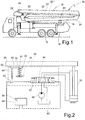
- Fig. 2
- ein Blockschaltbild einer nicht erfindungsgemäßen Schutzschaltung zur Begrenzung der Mastablagekraft auf dem Mastbock.
- Der Betonverteilermast 16 umfasst mehrere relativ zueinander verschwenkbare Mastarme 22 (22',22",22'''), die als faltbares Armpaket 24 über ein Drehgelenk 26 am fahrzeugseitigen Ende des ersten Mastarms an einem Drehkopf 28 angelenkt sind. Der Drehkopf 28 ist um eine Hochachse drehbar auf dem Fahrzeug 12 gelagert, während das Drehgelenk 26 eine horizontale Drehachse besitzt. Um das Armpaket 24 um das Drehgelenk 26 zu verschwenken, ist ein erster Hydraulikzylinder 30 vorgesehen, der mit seinen Enden an Anlenkstellen des Drehkopfs 28 und des ersten Mastarms 22' angelenkt ist. Zum Entfalten der weiteren Mastarme sind nicht gezeigte weitere Hydraulikzylinder in an sich bekannter Weise an dem Betonverteilermast 16 angeordnet.
- In der in
Fig. 1 gezeigten Transport- bzw. Fahrstellung ist der erste Mastarm 22' horizontal ausgerichtet bzw. nur gering geneigt. Um bestimmte Betonieraufgaben im ausgefalteten Zustand zu ermöglichen, kann jedoch eine weitere Neigung erforderlich sein, so dass der Zylinderhub nicht auf die Transportstellung begrenzt werden kann. Daraus entsteht das Problem, dass das Armpaket 24 beim Ablegen auf dem Mastbock 14 über den Hydraulikzylinder 30 so stark nach unten gedrückt werden kann, dass das Fahrgestell bzw. der Aufbaurahmen, auf dem sich der Mastbock 14 abstützt, beschädigt wird. Um dies zu verhindern, wird durch die Schutzschaltung 20 die Vertikalkraft des Armpakets 24 auf den Mastbock 14 definiert begrenzt.
Wie inFig. 2 mit vereinfachter Darstellung der Hydraulikschaltung veranschaulicht, umfasst die nicht erfindungsgemäße Schutzschaltung 20 eine die Last auf dem Mastbock 14 sensierende Schalteinheit 32 und ein mit dem ersten Hydraulikzylinder 30 gekoppeltes hydraulisches Stellglied in Form eines Wegeventils 34. Die Schalteinheit 32 weist ein beim Ablegen des Armpakets 24 elastisch verformbares Lastaufnahmeelement 36 auf. Dieses bildet einen Teil des Lastpfades 37 zur Ableitung des Gewichts des Armpakets 24 auf das Fahrzeug 12, wobei sichergestellt sein sollte, dass die Krafteinleitung eindeutig ist und das Armpaket 24 nur über das Lastaufnahmeelement 36 auf dem Mastbock 14 abgestützt ist.
Das Lastaufnahmeelement 36 bildet dabei einen Kraftsensor, über dessen Deformation bzw. elastische Verformung die auf den Mastbock 14 wirkende Vertikalkraft erfassbar ist. Zweckmäßig sollte die Grenzkraft nicht wesentlich größer als die Gewichtskraft des Armpakets 24 sein. Zu diesem Zweck kann das Lastaufnahmeelement 36 durch ein Tellerfederpaket 38 gebildet sein, welches auf eine maximale Federkraft von 10 bis 20 kN ausgelegt ist. Das Tellerfederpaket 38 kann in einem nicht gezeigten Federgehäuse auf dem Mastbock 14 integriert sein und über einen nach oben ragenden Stempel 40 eine Stützstelle für das Ablegen des Armpakets 24 bilden. - Die Schalteinheit 32 umfasst weiterhin einen Endschalter 42, der am Ende eines vorbestimmten Verformungs- bzw. Federwegs des Lastaufnahmeelements 36 auslöst und die Ablagebewegung stoppt. Zu diesem Zweck ist ein durch das Armpaket 24 in Verformungsrichtung des Lastaufnahmeelements 36 bewegbarer Schaltstößel 44 vorgesehen, der am Ende des vorbestimmten Verformungswegs als Tastorgan den elektrischen Endschalter 42 öffnet.
- Das Stellglied 34 ermöglicht als 4/3-Wegeventil eine Ansteuerung des ersten Hydraulikzylinders 30 in zwei aktive Bewegungsrichtungen mittels einer Bedieneinheit 46. In der gezeigten federzentrierten Mittelstellung des Wegeventils 34 ist die Pumpe 48 auf den Tank 50 durchgeschaltet, und der Hydraulikzylinder 30 bleibt unter boden- und stangenseitigem Druck selbsthaltend vorgespannt. In der rechten Schaltstellung ist der Hydraulikzylinder 30 in Ausfahrrichtung beaufschlagt, um das Armpaket 24 anzuheben. In der linken Schaltstellung wird der Hydraulikzylinder 30 stangenseitig mit Drucköl versorgt, so dass das Armpaket 24 auf dem Mastbock 14 unter Schwerkraft abgelegt und gegebenenfalls noch zusätzlich hydraulisch angedrückt wird. Die Kraftbegrenzung erfolgt dann automatisch dadurch, dass der Endschalter 42 den elektromagnetischen Steueranschluss 52 von der Bedieneinheit 46 trennt. Zugleich kann dabei über eine Signaleinheit 54 ein optisches oder akustisches Signal für den Bediener abgegeben werden.
- In einer abgewandelten Ausführungsform ist es auch möglich, ein gummielastisches Lastaufnahmeelement einzusetzen. Anstelle eines Endschalters kann ein Drucksensor eingesetzt werden. Alternativ kann das Lastaufnahmeelement über seinen elastischen Verformungsweg auch direkt auf ein Hydraulikventil wirken und die Ölzufuhr zum Hydraulikzylinder unterbrechen. Denkbar ist es für eine Schutzschaltung auch, einen direkten Kraftaufnehmer mit einem Schaltausgang zwischen Armpaket und Mastbock anzuordnen. Eine weitere Möglichkeit besteht in einer unmittelbaren Verformungsmessung am Armpaket oder Mastbock mittels Dehnungsmessstreifen. Alternativ ist es auch möglich, die Last des Armpakets mittelbar über boden- und stangenseitige Druckaufnehmer in dem Hydraulikzylinder zu bestimmen, wobei der Kontakt mit dem Mastbock zusätzlich über einen Schalter abgefragt wird.
Claims (9)
- Autobetonpumpe mit einem Fahrzeug (12) und einem darauf angeordneten Betonverteilermast (16), welcher mehrere als Armpaket (24) auf einer fahrzeugfesten Mastauflageeinheit (14) ablegbare Mastarme (22) besitzt, und einer zum Ablegen und Entfalten des Armpakets (24) ausgebildeten Masthydraulik, welche mindestens einen das Armpaket (24) in einer Ablagebewegung gegen die Mastauflageeinheit (14) bewegenden Hydraulikzylinder (30) aufweist, gekennzeichnet durch eine mit dem Hydraulikzylinder (30) gekoppelte und die Ablagebewegung beendende Schutzschaltung (20), welche eine unter der Last des Armpakets (24) betätigbare Schalteinheit (32) umfasst, wobei die Schalteinheit (32) ein an der Mastauflageeinheit (14) angeordnetes, beim Ablegen des Armpakets (24) elastisch verformbares Lastaufnahmeelement (36) aufweist, und wobei das Armpaket (24) nur über das Lastaufnahmeelement (36) auf der Mastauflageeinheit (14) abgestützt ist.
- Autobetonpumpe nach Anspruch 1, dadurch gekennzeichnet, dass das Lastaufnahmeelement (36) zur elastischen Aufnahme einer Kraft von mindestens 1 kN, vorzugsweise mehr als 10 kN ausgelegt ist.
- Autobetonpumpe nach Anspruch 1 oder 2, dadurch gekennzeichnet, dass das Lastaufnahmeelement (36) eine durch das Armpaket (24) komprimierbare Federanordnung (38), insbesondere ein Tellerfederpaket aufweist.
- Autobetonpumpe nach einem der Ansprüche 1 bis 3, dadurch gekennzeichnet, dass die Schalteinheit (32) einen am Ende der Ablagebewegung auslösenden Endschalter (42) aufweist, der die Ablagebewegung selbsttätig beendet.
- Autobetonpumpe nach einem der Ansprüche 1 bis 4, dadurch gekennzeichnet, dass die Schutzschaltung (20) ein mit dem Hydraulikzylinder (30) verbundenes hydraulisches Stellglied (34) aufweist.
- Autobetonpumpe nach Anspruch 5, dadurch gekennzeichnet, dass das Stellglied (34) ein Wegeventil ist.
- Autobetonpumpe nach Anspruch 6, dadurch gekennzeichnet, dass der Endschalter (42) einen Steueranschluss des Wegeventils von einer Bedieneinrichtung (46) trennt.
- Autobetonpumpe nach einem der Ansprüche 1 bis 7, dadurch gekennzeichnet, dass der Hydraulikzylinder (30) an einem ersten Mastarm (22') des Armpakets (24) angelenkt ist, und dass die Schutzschaltung (20) zum Beenden der Ablagebewegung die Druckölversorgung mindestens eines Hydraulikzylinders (30) des Armpakets (24) unterbricht.
- Autobetonpumpe nach einem der Ansprüche 1 bis 8, dadurch gekennzeichnet, dass beim Ansprechen der Schutzschaltung (20) ein Signal für einen Bediener des Betonverteilermasts (16) abgegeben wird.
Applications Claiming Priority (2)
| Application Number | Priority Date | Filing Date | Title |
|---|---|---|---|
| DE102014200396.2A DE102014200396A1 (de) | 2014-01-13 | 2014-01-13 | Autobetonpumpe und Schutzschaltung dafür |
| PCT/EP2015/050397 WO2015104410A1 (de) | 2014-01-13 | 2015-01-12 | Autobetonpumpe und schutzschaltung dafür |
Publications (2)
| Publication Number | Publication Date |
|---|---|
| EP3094793A1 EP3094793A1 (de) | 2016-11-23 |
| EP3094793B1 true EP3094793B1 (de) | 2018-03-14 |
Family
ID=52434739
Family Applications (1)
| Application Number | Title | Priority Date | Filing Date |
|---|---|---|---|
| EP15701689.0A Active EP3094793B1 (de) | 2014-01-13 | 2015-01-12 | Autobetonpumpe |
Country Status (8)
| Country | Link |
|---|---|
| US (1) | US9856661B2 (de) |
| EP (1) | EP3094793B1 (de) |
| JP (1) | JP6496741B2 (de) |
| KR (1) | KR102308314B1 (de) |
| CN (1) | CN106133259B (de) |
| DE (1) | DE102014200396A1 (de) |
| TR (1) | TR201807810T4 (de) |
| WO (1) | WO2015104410A1 (de) |
Families Citing this family (4)
| Publication number | Priority date | Publication date | Assignee | Title |
|---|---|---|---|---|
| DE102014200396A1 (de) * | 2014-01-13 | 2015-07-30 | Putzmeister Engineering Gmbh | Autobetonpumpe und Schutzschaltung dafür |
| KR101957099B1 (ko) * | 2018-05-08 | 2019-03-11 | 강봉조 | 콘크리트 분배기 |
| CN114517578B (zh) * | 2020-11-20 | 2023-04-28 | 三一汽车制造有限公司 | 作业车辆 |
| JP7731133B2 (ja) * | 2022-05-27 | 2025-08-29 | 株式会社ササキコーポレーション | 作業機 |
Family Cites Families (48)
| Publication number | Priority date | Publication date | Assignee | Title |
|---|---|---|---|---|
| JPS5245964U (de) * | 1975-09-29 | 1977-03-31 | ||
| DE3016232A1 (de) * | 1980-04-26 | 1981-11-05 | Karl Dipl.-Ing. 7000 Stuttgart Schlecht | Selbstfahrende betonpumpe |
| JPS57165688U (de) * | 1981-04-13 | 1982-10-19 | ||
| US4828033A (en) * | 1981-06-30 | 1989-05-09 | Dowell Schlumberger Incorporated | Apparatus and method for treatment of wells |
| US4424985A (en) * | 1981-09-08 | 1984-01-10 | J. I. Case Company | Outrigger support arrangement |
| GB8406094D0 (en) * | 1984-03-08 | 1984-04-11 | Merryweather & Sons | Control system |
| JPH0238991Y2 (de) * | 1985-02-08 | 1990-10-19 | ||
| JPS646469A (en) * | 1987-06-25 | 1989-01-11 | Kyokuto Kaihatsu Kogyo Co | Safety apparatus of concrete pump vehicle |
| DE3807966A1 (de) * | 1988-03-10 | 1989-09-21 | Ruthmann Anton Gmbh & Co | Hubarbeitsbuehne mit prozessorsteuerung |
| DE4208831A1 (de) * | 1992-03-19 | 1993-09-23 | Putzmeister Maschf | Autobetonpumpe |
| DE4233171A1 (de) * | 1992-10-02 | 1994-04-07 | Putzmeister Maschf | Betonverteilermast |
| DE4306127C2 (de) * | 1993-02-27 | 2002-08-08 | Putzmeister Ag | Großmanipulator, insbesondere für Autobetonpumpen |
| DE4330137A1 (de) * | 1993-09-07 | 1995-03-09 | Putzmeister Maschf | Hydraulisches Druckversorgungs- und Steueraggregat für eine Autobetonpumpe |
| JP3113808B2 (ja) * | 1995-11-30 | 2000-12-04 | 日立建機株式会社 | タワークレーン |
| JPH09323899A (ja) * | 1996-06-04 | 1997-12-16 | Aichi Corp | 作業車のキャビン保護装置 |
| DE19736109A1 (de) * | 1997-08-21 | 1999-02-25 | Putzmeister Ag | Fahrbare Arbeitsmaschine mit teleskopierbaren Stützauslegern |
| DE29811097U1 (de) * | 1998-06-20 | 1998-08-20 | Waitzinger Baumaschinen Vertrieb und Service GmbH, 89278 Nersingen | Fahrbare Betonpumpe |
| US6142180A (en) * | 2000-04-12 | 2000-11-07 | Woodling; Roger M. | Crane-mounted concrete pump apparatus |
| DE10110840A1 (de) * | 2001-01-30 | 2002-08-01 | Putzmeister Ag | Mobile Arbeitsmaschine mit begehbaren Pritschen |
| DE10112086A1 (de) * | 2001-03-12 | 2002-09-26 | Putzmeister Ag | Verteilervorrichtung für Dickstoffe |
| DE10246447A1 (de) * | 2002-10-04 | 2004-04-15 | Putzmeister Ag | Fahrbare Betonpumpe mit einem Aufbaurahmen |
| US6779688B1 (en) * | 2002-10-08 | 2004-08-24 | Putzmeister, Inc. | Catch basin for a concrete pumping device |
| DE10328767A1 (de) * | 2003-06-25 | 2005-01-20 | Putzmeister Ag | Fahrbare Betonpumpe mit Verteilermast |
| DE10328769A1 (de) * | 2003-06-25 | 2005-01-20 | Putzmeister Ag | Knickmast für fahrbare Betonpumpen |
| DE102004007509A1 (de) * | 2004-02-13 | 2005-09-01 | Putzmeister Ag | Autobetonpumpe mit einer fahrgestellfesten Mastauflageeinheit für einen Verteilermast |
| DE102006031257A1 (de) * | 2006-07-06 | 2008-01-10 | Putzmeister Ag | Autobetonpumpe mit Knickmast |
| JP2008056373A (ja) * | 2006-08-29 | 2008-03-13 | Aichi Corp | 作業用車両の安全装置 |
| DE102008007917A1 (de) * | 2008-02-06 | 2009-08-13 | Putzmeister Concrete Pumps Gmbh | Fahrbare Arbeitsmaschine |
| DE102008007918A1 (de) * | 2008-02-06 | 2009-08-13 | Putzmeister Concrete Pumps Gmbh | Fahrbare Arbeitsmaschine |
| CN201538657U (zh) * | 2009-09-29 | 2010-08-04 | 李辉照 | 工程机械支腿机械锁止装置 |
| IT1398962B1 (it) * | 2010-02-18 | 2013-03-28 | C M C S R L Societa Unipersonale | Dispositivo stabilizzatore per macchina operatrice |
| DE102011078783A1 (de) * | 2011-07-07 | 2013-01-10 | Putzmeister Engineering Gmbh | Verteilermast für Betonpumpen |
| AT511833B1 (de) * | 2011-11-10 | 2013-03-15 | Schwing Gmbh F | Mastaufbau insbesondere für eine autobetonpumpe |
| CN102518305B (zh) * | 2011-12-13 | 2013-08-28 | 中联重科股份有限公司 | 混凝土泵车的臂架及混凝土泵车 |
| CN202493871U (zh) * | 2012-03-30 | 2012-10-17 | 杨奉钦 | 限位支撑装置 |
| DE102012207568A1 (de) * | 2012-04-13 | 2013-10-17 | Putzmeister Engineering Gmbh | Herstellungsverfahren für einen Mastarm und Betonverteilermast |
| DE102012213729A1 (de) * | 2012-08-02 | 2014-02-06 | Putzmeister Engineering Gmbh | Betonverteilermast für Betonpumpen |
| DE102012215049A1 (de) * | 2012-08-24 | 2014-03-20 | Putzmeister Engineering Gmbh | Fahrbare Betonpumpe |
| DE102012215050A1 (de) * | 2012-08-24 | 2014-03-27 | Putzmeister Engineering Gmbh | Fahrbare Betonpumpe |
| DE102012215469A1 (de) * | 2012-08-31 | 2014-03-06 | Putzmeister Engineering Gmbh | Betonverteilermast |
| CN103010966B (zh) * | 2012-12-14 | 2015-03-25 | 中国长江三峡集团公司 | 多功能物料输送、布料及起重设备 |
| DE102012224529A1 (de) * | 2012-12-28 | 2014-07-03 | Putzmeister Engineering Gmbh | Arbeitsgerät mit Drehkopf-Trennstelle |
| DE102013205888A1 (de) * | 2013-04-03 | 2014-10-09 | Putzmeister Engineering Gmbh | Fahrbare Arbeitsmaschine, insbesondere Autobetonpumpe und Herstellungsverfahren |
| DE102013206366A1 (de) * | 2013-04-11 | 2014-10-16 | Putzmeister Engineering Gmbh | Fahrbare Betonpumpe mit Verteilermast und Abstützvorrichtung |
| DE102013209878A1 (de) * | 2013-05-28 | 2014-12-04 | Putzmeister Engineering Gmbh | Arbeitsgerät mit an einem Drehkopf angeordneten Arbeitsausleger |
| CA2923757C (en) * | 2013-09-06 | 2023-09-19 | Putzmeister Engineering Gmbh | Truck mounted concrete pump and method for operation thereof |
| DE102014200396A1 (de) * | 2014-01-13 | 2015-07-30 | Putzmeister Engineering Gmbh | Autobetonpumpe und Schutzschaltung dafür |
| DE102014208472A1 (de) * | 2014-05-06 | 2015-11-12 | Putzmeister Engineering Gmbh | Autobetonpumpe |
-
2014
- 2014-01-13 DE DE102014200396.2A patent/DE102014200396A1/de not_active Withdrawn
-
2015
- 2015-01-12 JP JP2016545931A patent/JP6496741B2/ja active Active
- 2015-01-12 TR TR2018/07810T patent/TR201807810T4/tr unknown
- 2015-01-12 WO PCT/EP2015/050397 patent/WO2015104410A1/de not_active Ceased
- 2015-01-12 CN CN201580004430.3A patent/CN106133259B/zh active Active
- 2015-01-12 KR KR1020167018106A patent/KR102308314B1/ko active Active
- 2015-01-12 EP EP15701689.0A patent/EP3094793B1/de active Active
-
2016
- 2016-07-11 US US15/207,447 patent/US9856661B2/en active Active
Also Published As
| Publication number | Publication date |
|---|---|
| JP2017506296A (ja) | 2017-03-02 |
| DE102014200396A1 (de) | 2015-07-30 |
| WO2015104410A1 (de) | 2015-07-16 |
| KR102308314B1 (ko) | 2021-10-05 |
| US20160326755A1 (en) | 2016-11-10 |
| CN106133259B (zh) | 2019-05-07 |
| US9856661B2 (en) | 2018-01-02 |
| CN106133259A (zh) | 2016-11-16 |
| TR201807810T4 (tr) | 2018-06-21 |
| EP3094793A1 (de) | 2016-11-23 |
| KR20160108326A (ko) | 2016-09-19 |
| JP6496741B2 (ja) | 2019-04-03 |
Similar Documents
| Publication | Publication Date | Title |
|---|---|---|
| DE3409476C2 (de) | ||
| EP2640911B1 (de) | Mobiles arbeitsgerät mit abstützkonstruktion | |
| EP2984253B1 (de) | Fahrbare betonpumpe mit verteilermast und abstützvorrichtung | |
| EP2238071B1 (de) | Fahrbare arbeitsmaschine | |
| EP2705201B1 (de) | Autobetonpumpe mit Abstützvorrichtung | |
| EP2729645B1 (de) | Verteilermast für betonpumpen | |
| EP1937913A1 (de) | Arbeitsmast, insbesondere für grossmanipulatoren und fahrbare betonpumpen | |
| DE10349234A1 (de) | Mobiles Arbeitsgerät mit Stützauslegern | |
| EP3094793B1 (de) | Autobetonpumpe | |
| EP1752587A1 (de) | Hydraulische Anordnung | |
| EP3003955B1 (de) | Arbeitsgerät mit an einem drehkopf angeordnetem arbeitsausleger | |
| EP3027476B1 (de) | Landfahrzeug mit einer mehrzahl von eckstützeinheiten | |
| DE102006049487A1 (de) | Arbeitsmast, insbesondere für Großmanipulatoren und fahrbare Betonpumpen | |
| DE2253755C3 (de) | Vorrichtung zum automatischen horizontalen Ausrichten eines Trägerfahrzeugs für einen Kran o.dgl | |
| DE202007002115U1 (de) | Teleskopische Abstützeinrichtung für mobile Fahrzeuge | |
| EP2881524B1 (de) | Autobetonpumpe mit einer Mastauflageeinheit für einen Verteilermast | |
| EP3833627B1 (de) | Fahrzeugkransystem mit einer anbauteil-transporteinheit für eine abspanneinrichtung, insbesondere einen seitlichen superlift, eines fahrzeugkrans | |
| WO2011009537A1 (de) | Fahrzeug mit ausschwenkbarem mastarmaufbau | |
| EP2664576B1 (de) | Querkraftreduzierende Abstützeinrichtung | |
| DE102012001185A1 (de) | Verfahren zum Betrieb eines ortsveränderbaren Arbeitsgerätes, sowie ein Arbeitsgerät zur Ausführung des Verfahrens | |
| DE102013008434B4 (de) | Autobetonpumpe mit Unterfahrschutz | |
| DE1456422A1 (de) | Einrichtung zur Begrenzung des von Fahrzeugen mit aufgebautem Schwenkkran maximal aufnehmbaren Lastmoments | |
| EP3943440B1 (de) | Hydrauliksystem für eine rückfallstütze und arbeitsgerät | |
| DE102017113423B4 (de) | Vorrichtung zur nivellierten Ausrichtung/Anhebung eines Fahrzeuges, sowie Verfahren zum Betrieb einer Vorrichtung zur nivellierten Anhebung eines Fahrzeuges | |
| DE102013222798A1 (de) | Autobetonpumpe |
Legal Events
| Date | Code | Title | Description |
|---|---|---|---|
| PUAI | Public reference made under article 153(3) epc to a published international application that has entered the european phase |
Free format text: ORIGINAL CODE: 0009012 |
|
| 17P | Request for examination filed |
Effective date: 20160805 |
|
| AK | Designated contracting states |
Kind code of ref document: A1 Designated state(s): AL AT BE BG CH CY CZ DE DK EE ES FI FR GB GR HR HU IE IS IT LI LT LU LV MC MK MT NL NO PL PT RO RS SE SI SK SM TR |
|
| AX | Request for extension of the european patent |
Extension state: BA ME |
|
| RIN1 | Information on inventor provided before grant (corrected) |
Inventor name: KASTEN, KNUT Inventor name: WESTERMANN, KARL |
|
| DAX | Request for extension of the european patent (deleted) | ||
| GRAP | Despatch of communication of intention to grant a patent |
Free format text: ORIGINAL CODE: EPIDOSNIGR1 |
|
| STAA | Information on the status of an ep patent application or granted ep patent |
Free format text: STATUS: GRANT OF PATENT IS INTENDED |
|
| INTG | Intention to grant announced |
Effective date: 20170911 |
|
| GRAS | Grant fee paid |
Free format text: ORIGINAL CODE: EPIDOSNIGR3 |
|
| GRAA | (expected) grant |
Free format text: ORIGINAL CODE: 0009210 |
|
| STAA | Information on the status of an ep patent application or granted ep patent |
Free format text: STATUS: THE PATENT HAS BEEN GRANTED |
|
| AK | Designated contracting states |
Kind code of ref document: B1 Designated state(s): AL AT BE BG CH CY CZ DE DK EE ES FI FR GB GR HR HU IE IS IT LI LT LU LV MC MK MT NL NO PL PT RO RS SE SI SK SM TR |
|
| REG | Reference to a national code |
Ref country code: GB Ref legal event code: FG4D Free format text: NOT ENGLISH |
|
| REG | Reference to a national code |
Ref country code: CH Ref legal event code: EP Ref country code: AT Ref legal event code: REF Ref document number: 979037 Country of ref document: AT Kind code of ref document: T Effective date: 20180315 |
|
| REG | Reference to a national code |
Ref country code: IE Ref legal event code: FG4D Free format text: LANGUAGE OF EP DOCUMENT: GERMAN |
|
| REG | Reference to a national code |
Ref country code: DE Ref legal event code: R096 Ref document number: 502015003404 Country of ref document: DE |
|
| REG | Reference to a national code |
Ref country code: NL Ref legal event code: MP Effective date: 20180314 |
|
| REG | Reference to a national code |
Ref country code: LT Ref legal event code: MG4D |
|
| PG25 | Lapsed in a contracting state [announced via postgrant information from national office to epo] |
Ref country code: LT Free format text: LAPSE BECAUSE OF FAILURE TO SUBMIT A TRANSLATION OF THE DESCRIPTION OR TO PAY THE FEE WITHIN THE PRESCRIBED TIME-LIMIT Effective date: 20180314 Ref country code: HR Free format text: LAPSE BECAUSE OF FAILURE TO SUBMIT A TRANSLATION OF THE DESCRIPTION OR TO PAY THE FEE WITHIN THE PRESCRIBED TIME-LIMIT Effective date: 20180314 Ref country code: CY Free format text: LAPSE BECAUSE OF FAILURE TO SUBMIT A TRANSLATION OF THE DESCRIPTION OR TO PAY THE FEE WITHIN THE PRESCRIBED TIME-LIMIT Effective date: 20180314 Ref country code: NO Free format text: LAPSE BECAUSE OF FAILURE TO SUBMIT A TRANSLATION OF THE DESCRIPTION OR TO PAY THE FEE WITHIN THE PRESCRIBED TIME-LIMIT Effective date: 20180614 Ref country code: FI Free format text: LAPSE BECAUSE OF FAILURE TO SUBMIT A TRANSLATION OF THE DESCRIPTION OR TO PAY THE FEE WITHIN THE PRESCRIBED TIME-LIMIT Effective date: 20180314 |
|
| PG25 | Lapsed in a contracting state [announced via postgrant information from national office to epo] |
Ref country code: GR Free format text: LAPSE BECAUSE OF FAILURE TO SUBMIT A TRANSLATION OF THE DESCRIPTION OR TO PAY THE FEE WITHIN THE PRESCRIBED TIME-LIMIT Effective date: 20180615 Ref country code: LV Free format text: LAPSE BECAUSE OF FAILURE TO SUBMIT A TRANSLATION OF THE DESCRIPTION OR TO PAY THE FEE WITHIN THE PRESCRIBED TIME-LIMIT Effective date: 20180314 Ref country code: SE Free format text: LAPSE BECAUSE OF FAILURE TO SUBMIT A TRANSLATION OF THE DESCRIPTION OR TO PAY THE FEE WITHIN THE PRESCRIBED TIME-LIMIT Effective date: 20180314 Ref country code: RS Free format text: LAPSE BECAUSE OF FAILURE TO SUBMIT A TRANSLATION OF THE DESCRIPTION OR TO PAY THE FEE WITHIN THE PRESCRIBED TIME-LIMIT Effective date: 20180314 Ref country code: BG Free format text: LAPSE BECAUSE OF FAILURE TO SUBMIT A TRANSLATION OF THE DESCRIPTION OR TO PAY THE FEE WITHIN THE PRESCRIBED TIME-LIMIT Effective date: 20180614 |
|
| PG25 | Lapsed in a contracting state [announced via postgrant information from national office to epo] |
Ref country code: MT Free format text: LAPSE BECAUSE OF FAILURE TO SUBMIT A TRANSLATION OF THE DESCRIPTION OR TO PAY THE FEE WITHIN THE PRESCRIBED TIME-LIMIT Effective date: 20180314 |
|
| PG25 | Lapsed in a contracting state [announced via postgrant information from national office to epo] |
Ref country code: EE Free format text: LAPSE BECAUSE OF FAILURE TO SUBMIT A TRANSLATION OF THE DESCRIPTION OR TO PAY THE FEE WITHIN THE PRESCRIBED TIME-LIMIT Effective date: 20180314 Ref country code: PL Free format text: LAPSE BECAUSE OF FAILURE TO SUBMIT A TRANSLATION OF THE DESCRIPTION OR TO PAY THE FEE WITHIN THE PRESCRIBED TIME-LIMIT Effective date: 20180314 Ref country code: AL Free format text: LAPSE BECAUSE OF FAILURE TO SUBMIT A TRANSLATION OF THE DESCRIPTION OR TO PAY THE FEE WITHIN THE PRESCRIBED TIME-LIMIT Effective date: 20180314 Ref country code: ES Free format text: LAPSE BECAUSE OF FAILURE TO SUBMIT A TRANSLATION OF THE DESCRIPTION OR TO PAY THE FEE WITHIN THE PRESCRIBED TIME-LIMIT Effective date: 20180314 Ref country code: RO Free format text: LAPSE BECAUSE OF FAILURE TO SUBMIT A TRANSLATION OF THE DESCRIPTION OR TO PAY THE FEE WITHIN THE PRESCRIBED TIME-LIMIT Effective date: 20180314 Ref country code: NL Free format text: LAPSE BECAUSE OF FAILURE TO SUBMIT A TRANSLATION OF THE DESCRIPTION OR TO PAY THE FEE WITHIN THE PRESCRIBED TIME-LIMIT Effective date: 20180314 |
|
| PG25 | Lapsed in a contracting state [announced via postgrant information from national office to epo] |
Ref country code: CZ Free format text: LAPSE BECAUSE OF FAILURE TO SUBMIT A TRANSLATION OF THE DESCRIPTION OR TO PAY THE FEE WITHIN THE PRESCRIBED TIME-LIMIT Effective date: 20180314 Ref country code: SM Free format text: LAPSE BECAUSE OF FAILURE TO SUBMIT A TRANSLATION OF THE DESCRIPTION OR TO PAY THE FEE WITHIN THE PRESCRIBED TIME-LIMIT Effective date: 20180314 Ref country code: SK Free format text: LAPSE BECAUSE OF FAILURE TO SUBMIT A TRANSLATION OF THE DESCRIPTION OR TO PAY THE FEE WITHIN THE PRESCRIBED TIME-LIMIT Effective date: 20180314 |
|
| REG | Reference to a national code |
Ref country code: DE Ref legal event code: R097 Ref document number: 502015003404 Country of ref document: DE |
|
| PG25 | Lapsed in a contracting state [announced via postgrant information from national office to epo] |
Ref country code: PT Free format text: LAPSE BECAUSE OF FAILURE TO SUBMIT A TRANSLATION OF THE DESCRIPTION OR TO PAY THE FEE WITHIN THE PRESCRIBED TIME-LIMIT Effective date: 20180716 |
|
| PLBE | No opposition filed within time limit |
Free format text: ORIGINAL CODE: 0009261 |
|
| STAA | Information on the status of an ep patent application or granted ep patent |
Free format text: STATUS: NO OPPOSITION FILED WITHIN TIME LIMIT |
|
| PG25 | Lapsed in a contracting state [announced via postgrant information from national office to epo] |
Ref country code: DK Free format text: LAPSE BECAUSE OF FAILURE TO SUBMIT A TRANSLATION OF THE DESCRIPTION OR TO PAY THE FEE WITHIN THE PRESCRIBED TIME-LIMIT Effective date: 20180314 |
|
| 26N | No opposition filed |
Effective date: 20181217 |
|
| PG25 | Lapsed in a contracting state [announced via postgrant information from national office to epo] |
Ref country code: SI Free format text: LAPSE BECAUSE OF FAILURE TO SUBMIT A TRANSLATION OF THE DESCRIPTION OR TO PAY THE FEE WITHIN THE PRESCRIBED TIME-LIMIT Effective date: 20180314 |
|
| PG25 | Lapsed in a contracting state [announced via postgrant information from national office to epo] |
Ref country code: MC Free format text: LAPSE BECAUSE OF FAILURE TO SUBMIT A TRANSLATION OF THE DESCRIPTION OR TO PAY THE FEE WITHIN THE PRESCRIBED TIME-LIMIT Effective date: 20180314 |
|
| REG | Reference to a national code |
Ref country code: CH Ref legal event code: PL |
|
| GBPC | Gb: european patent ceased through non-payment of renewal fee |
Effective date: 20190112 |
|
| PG25 | Lapsed in a contracting state [announced via postgrant information from national office to epo] |
Ref country code: LU Free format text: LAPSE BECAUSE OF NON-PAYMENT OF DUE FEES Effective date: 20190112 |
|
| REG | Reference to a national code |
Ref country code: BE Ref legal event code: MM Effective date: 20190131 |
|
| REG | Reference to a national code |
Ref country code: IE Ref legal event code: MM4A |
|
| PG25 | Lapsed in a contracting state [announced via postgrant information from national office to epo] |
Ref country code: FR Free format text: LAPSE BECAUSE OF NON-PAYMENT OF DUE FEES Effective date: 20190131 |
|
| PG25 | Lapsed in a contracting state [announced via postgrant information from national office to epo] |
Ref country code: BE Free format text: LAPSE BECAUSE OF NON-PAYMENT OF DUE FEES Effective date: 20190131 |
|
| PG25 | Lapsed in a contracting state [announced via postgrant information from national office to epo] |
Ref country code: CH Free format text: LAPSE BECAUSE OF NON-PAYMENT OF DUE FEES Effective date: 20190131 Ref country code: GB Free format text: LAPSE BECAUSE OF NON-PAYMENT OF DUE FEES Effective date: 20190112 Ref country code: LI Free format text: LAPSE BECAUSE OF NON-PAYMENT OF DUE FEES Effective date: 20190131 |
|
| PG25 | Lapsed in a contracting state [announced via postgrant information from national office to epo] |
Ref country code: IE Free format text: LAPSE BECAUSE OF NON-PAYMENT OF DUE FEES Effective date: 20190112 |
|
| REG | Reference to a national code |
Ref country code: AT Ref legal event code: MM01 Ref document number: 979037 Country of ref document: AT Kind code of ref document: T Effective date: 20200112 |
|
| PG25 | Lapsed in a contracting state [announced via postgrant information from national office to epo] |
Ref country code: AT Free format text: LAPSE BECAUSE OF NON-PAYMENT OF DUE FEES Effective date: 20200112 |
|
| PG25 | Lapsed in a contracting state [announced via postgrant information from national office to epo] |
Ref country code: IS Free format text: LAPSE BECAUSE OF FAILURE TO SUBMIT A TRANSLATION OF THE DESCRIPTION OR TO PAY THE FEE WITHIN THE PRESCRIBED TIME-LIMIT Effective date: 20180714 |
|
| PG25 | Lapsed in a contracting state [announced via postgrant information from national office to epo] |
Ref country code: HU Free format text: LAPSE BECAUSE OF FAILURE TO SUBMIT A TRANSLATION OF THE DESCRIPTION OR TO PAY THE FEE WITHIN THE PRESCRIBED TIME-LIMIT; INVALID AB INITIO Effective date: 20150112 |
|
| PG25 | Lapsed in a contracting state [announced via postgrant information from national office to epo] |
Ref country code: MK Free format text: LAPSE BECAUSE OF FAILURE TO SUBMIT A TRANSLATION OF THE DESCRIPTION OR TO PAY THE FEE WITHIN THE PRESCRIBED TIME-LIMIT Effective date: 20180314 |
|
| PGFP | Annual fee paid to national office [announced via postgrant information from national office to epo] |
Ref country code: DE Payment date: 20260121 Year of fee payment: 12 |
|
| PGFP | Annual fee paid to national office [announced via postgrant information from national office to epo] |
Ref country code: IT Payment date: 20260123 Year of fee payment: 12 |
|
| PGFP | Annual fee paid to national office [announced via postgrant information from national office to epo] |
Ref country code: TR Payment date: 20260109 Year of fee payment: 12 |