EP3109200A1 - Piece de micromecanique avec une surface de contact diminuee et son procede de fabrication - Google Patents
Piece de micromecanique avec une surface de contact diminuee et son procede de fabrication Download PDFInfo
- Publication number
- EP3109200A1 EP3109200A1 EP16170650.2A EP16170650A EP3109200A1 EP 3109200 A1 EP3109200 A1 EP 3109200A1 EP 16170650 A EP16170650 A EP 16170650A EP 3109200 A1 EP3109200 A1 EP 3109200A1
- Authority
- EP
- European Patent Office
- Prior art keywords
- etching
- walls
- silicon
- protective layer
- substrate
- Prior art date
- Legal status (The legal status is an assumption and is not a legal conclusion. Google has not performed a legal analysis and makes no representation as to the accuracy of the status listed.)
- Granted
Links
Images


Classifications
-
- B—PERFORMING OPERATIONS; TRANSPORTING
- B81—MICROSTRUCTURAL TECHNOLOGY
- B81B—MICROSTRUCTURAL DEVICES OR SYSTEMS, e.g. MICROMECHANICAL DEVICES
- B81B7/00—Microstructural systems; Auxiliary parts of microstructural devices or systems
- B81B7/0032—Packages or encapsulation
-
- B—PERFORMING OPERATIONS; TRANSPORTING
- B81—MICROSTRUCTURAL TECHNOLOGY
- B81B—MICROSTRUCTURAL DEVICES OR SYSTEMS, e.g. MICROMECHANICAL DEVICES
- B81B7/00—Microstructural systems; Auxiliary parts of microstructural devices or systems
- B81B7/0032—Packages or encapsulation
- B81B7/0074—3D packaging, i.e. encapsulation containing one or several MEMS devices arranged in planes non-parallel to the mounting board
-
- B—PERFORMING OPERATIONS; TRANSPORTING
- B81—MICROSTRUCTURAL TECHNOLOGY
- B81C—PROCESSES OR APPARATUS SPECIALLY ADAPTED FOR THE MANUFACTURE OR TREATMENT OF MICROSTRUCTURAL DEVICES OR SYSTEMS
- B81C1/00—Manufacture or treatment of devices or systems in or on a substrate
-
- B—PERFORMING OPERATIONS; TRANSPORTING
- B81—MICROSTRUCTURAL TECHNOLOGY
- B81C—PROCESSES OR APPARATUS SPECIALLY ADAPTED FOR THE MANUFACTURE OR TREATMENT OF MICROSTRUCTURAL DEVICES OR SYSTEMS
- B81C1/00—Manufacture or treatment of devices or systems in or on a substrate
- B81C1/00015—Manufacture or treatment of devices or systems in or on a substrate for manufacturing microsystems
- B81C1/00023—Manufacture or treatment of devices or systems in or on a substrate for manufacturing microsystems without movable or flexible elements
- B81C1/00103—Structures having a predefined profile, e.g. sloped or rounded grooves
-
- B—PERFORMING OPERATIONS; TRANSPORTING
- B81—MICROSTRUCTURAL TECHNOLOGY
- B81C—PROCESSES OR APPARATUS SPECIALLY ADAPTED FOR THE MANUFACTURE OR TREATMENT OF MICROSTRUCTURAL DEVICES OR SYSTEMS
- B81C1/00—Manufacture or treatment of devices or systems in or on a substrate
- B81C1/00388—Etch mask forming
-
- B—PERFORMING OPERATIONS; TRANSPORTING
- B81—MICROSTRUCTURAL TECHNOLOGY
- B81C—PROCESSES OR APPARATUS SPECIALLY ADAPTED FOR THE MANUFACTURE OR TREATMENT OF MICROSTRUCTURAL DEVICES OR SYSTEMS
- B81C1/00—Manufacture or treatment of devices or systems in or on a substrate
- B81C1/00436—Shaping materials, i.e. techniques for structuring the substrate or the layers on the substrate
- B81C1/00555—Achieving a desired geometry, i.e. controlling etch rates, anisotropy or selectivity
- B81C1/00619—Forming high aspect ratio structures having deep steep walls
-
- G—PHYSICS
- G04—HOROLOGY
- G04B—MECHANICALLY-DRIVEN CLOCKS OR WATCHES; MECHANICAL PARTS OF CLOCKS OR WATCHES IN GENERAL; TIME PIECES USING THE POSITION OF THE SUN, MOON OR STARS
- G04B13/00—Gearwork
- G04B13/02—Wheels; Pinions; Spindles; Pivots
-
- G04B13/026—
-
- G—PHYSICS
- G04—HOROLOGY
- G04B—MECHANICALLY-DRIVEN CLOCKS OR WATCHES; MECHANICAL PARTS OF CLOCKS OR WATCHES IN GENERAL; TIME PIECES USING THE POSITION OF THE SUN, MOON OR STARS
- G04B13/00—Gearwork
- G04B13/02—Wheels; Pinions; Spindles; Pivots
- G04B13/027—Wheels; Pinions; Spindles; Pivots planar toothing: shape and design
-
- G—PHYSICS
- G04—HOROLOGY
- G04D—APPARATUS OR TOOLS SPECIALLY DESIGNED FOR MAKING OR MAINTAINING CLOCKS OR WATCHES
- G04D99/00—Subject matter not provided for in other groups of this subclass
-
- B—PERFORMING OPERATIONS; TRANSPORTING
- B81—MICROSTRUCTURAL TECHNOLOGY
- B81B—MICROSTRUCTURAL DEVICES OR SYSTEMS, e.g. MICROMECHANICAL DEVICES
- B81B2201/00—Specific applications of microelectromechanical systems
- B81B2201/03—Microengines and actuators
- B81B2201/035—Microgears
-
- B—PERFORMING OPERATIONS; TRANSPORTING
- B81—MICROSTRUCTURAL TECHNOLOGY
- B81B—MICROSTRUCTURAL DEVICES OR SYSTEMS, e.g. MICROMECHANICAL DEVICES
- B81B2203/00—Basic microelectromechanical structures
- B81B2203/03—Static structures
- B81B2203/0369—Static structures characterized by their profile
- B81B2203/0384—Static structures characterized by their profile sloped profile
-
- B—PERFORMING OPERATIONS; TRANSPORTING
- B81—MICROSTRUCTURAL TECHNOLOGY
- B81C—PROCESSES OR APPARATUS SPECIALLY ADAPTED FOR THE MANUFACTURE OR TREATMENT OF MICROSTRUCTURAL DEVICES OR SYSTEMS
- B81C2201/00—Manufacture or treatment of microstructural devices or systems
- B81C2201/01—Manufacture or treatment of microstructural devices or systems in or on a substrate
- B81C2201/0101—Shaping material; Structuring the bulk substrate or layers on the substrate; Film patterning
- B81C2201/0111—Bulk micromachining
- B81C2201/0112—Bosch process
-
- B—PERFORMING OPERATIONS; TRANSPORTING
- B81—MICROSTRUCTURAL TECHNOLOGY
- B81C—PROCESSES OR APPARATUS SPECIALLY ADAPTED FOR THE MANUFACTURE OR TREATMENT OF MICROSTRUCTURAL DEVICES OR SYSTEMS
- B81C2201/00—Manufacture or treatment of microstructural devices or systems
- B81C2201/01—Manufacture or treatment of microstructural devices or systems in or on a substrate
- B81C2201/0101—Shaping material; Structuring the bulk substrate or layers on the substrate; Film patterning
- B81C2201/0128—Processes for removing material
- B81C2201/013—Etching
- B81C2201/0132—Dry etching, i.e. plasma etching, barrel etching, reactive ion etching [RIE], sputter etching or ion milling
-
- B—PERFORMING OPERATIONS; TRANSPORTING
- B81—MICROSTRUCTURAL TECHNOLOGY
- B81C—PROCESSES OR APPARATUS SPECIALLY ADAPTED FOR THE MANUFACTURE OR TREATMENT OF MICROSTRUCTURAL DEVICES OR SYSTEMS
- B81C2201/00—Manufacture or treatment of microstructural devices or systems
- B81C2201/01—Manufacture or treatment of microstructural devices or systems in or on a substrate
- B81C2201/0101—Shaping material; Structuring the bulk substrate or layers on the substrate; Film patterning
- B81C2201/0128—Processes for removing material
- B81C2201/013—Etching
- B81C2201/0135—Controlling etch progression
- B81C2201/0138—Monitoring physical parameters in the etching chamber, e.g. pressure, temperature or gas composition
-
- B—PERFORMING OPERATIONS; TRANSPORTING
- B81—MICROSTRUCTURAL TECHNOLOGY
- B81C—PROCESSES OR APPARATUS SPECIALLY ADAPTED FOR THE MANUFACTURE OR TREATMENT OF MICROSTRUCTURAL DEVICES OR SYSTEMS
- B81C2201/00—Manufacture or treatment of microstructural devices or systems
- B81C2201/01—Manufacture or treatment of microstructural devices or systems in or on a substrate
- B81C2201/0101—Shaping material; Structuring the bulk substrate or layers on the substrate; Film patterning
- B81C2201/0128—Processes for removing material
- B81C2201/013—Etching
- B81C2201/0135—Controlling etch progression
- B81C2201/014—Controlling etch progression by depositing an etch stop layer, e.g. silicon nitride, silicon oxide, metal
-
- B—PERFORMING OPERATIONS; TRANSPORTING
- B81—MICROSTRUCTURAL TECHNOLOGY
- B81C—PROCESSES OR APPARATUS SPECIALLY ADAPTED FOR THE MANUFACTURE OR TREATMENT OF MICROSTRUCTURAL DEVICES OR SYSTEMS
- B81C2201/00—Manufacture or treatment of microstructural devices or systems
- B81C2201/01—Manufacture or treatment of microstructural devices or systems in or on a substrate
- B81C2201/0174—Manufacture or treatment of microstructural devices or systems in or on a substrate for making multi-layered devices, film deposition or growing
- B81C2201/0183—Selective deposition
- B81C2201/0188—Selective deposition techniques not provided for in B81C2201/0184 - B81C2201/0187
-
- B—PERFORMING OPERATIONS; TRANSPORTING
- B81—MICROSTRUCTURAL TECHNOLOGY
- B81C—PROCESSES OR APPARATUS SPECIALLY ADAPTED FOR THE MANUFACTURE OR TREATMENT OF MICROSTRUCTURAL DEVICES OR SYSTEMS
- B81C2201/00—Manufacture or treatment of microstructural devices or systems
- B81C2201/01—Manufacture or treatment of microstructural devices or systems in or on a substrate
- B81C2201/0198—Manufacture or treatment of microstructural devices or systems in or on a substrate for making a masking layer
Definitions
- the invention relates to a micromechanical part with a reduced contact surface and its method of manufacture. More particularly, the invention relates to such a part formed by micromachining a wafer of material.
- the document CH 698 837 discloses the manufacture of a watch component by micromachining a wafer of amorphous or crystalline material such as silicon in crystalline or polycrystalline form.
- Such micromachining is generally obtained from a deep reactive ion etching (also known by the abbreviation "DRIE").
- a known micromachining consists of a structuring of a mask 1 on a substrate 3 (cf. Figure 1 , step A) followed by a deep reactive ion etching of the "Bosch" type successively combining an attack phase (cf. figure 1 , steps B, D, E) followed by a passivation phase (cf. figure 1 , step C, layer 4) to obtain, from the pattern of the mask 1, an anisotropic etching 5, that is to say substantially vertical, in the wafer (cf. figure 2 ).
- DRIE deep reactive ion etching
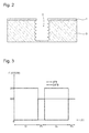
- an example of deep-reactive ion etching of the "Bosch" type is represented with, in full line, the flux in SCCM of SF 6 as a function of time in seconds allowing the etching of a silicon wafer and, in broken line, the SCCM flux of C 4 F 8 as a function of time in seconds allowing the passivation, that is to say the protection, of the silicon wafer.
- the phases are strictly consecutive and have a flow and a time of their own.
- a first etching phase G 1 is represented with a flow of SF 6 at 300 SCCM for 7 seconds, followed by a first passivation phase P 1 with a flow of C 4 F 8 at 200 SCCM for 2 seconds, followed by a second G 2 etching phase with SF 6 flux at 300 SCCM again for 7 seconds and finally followed by a second passivation phase P 2 with a flow of C 4 F 8 at 200 SCCM for 2 seconds, And so on.
- a certain number of parameters make it possible to vary the deep-reactive ionic etching of the "Bosch" type in order to have a more or less marked undulation of the wall of the vertical etching 5.
- the object of the present invention is to overcome all or part of the disadvantages mentioned above by proposing a new type of micromechanical part and a new type of manufacturing process including tribological improvement of parts formed by micro-machining a wafer of matter.
- step e) makes it possible to form a second substantially oblique surface to form several micromechanical parts on the same substrate having a peripheral wall with a reduced contact surface. It can also be seen that, thanks to the protective layer only on the vertical walls, the oblique engraving of step e) allows a much more open angle and a substantially straight etching direction that avoids being limited by the parameters of a deep-reactive ion etching of the "Bosch" type which is, on the other hand, used in step c) according to its optimized parameters of vertical etching.
- the invention relates to a micromechanical component obtained from the method according to one of the preceding variants, characterized in that it comprises a silicon-based body whose peripheral wall comprises a first substantially vertical surface and a second oblique surface for reducing the contact surface of the peripheral wall.
- the peripheral or vertical inner wall of the micromechanical part offers a reduction of its contact surface or the entry of a member along an inner wall of the micromechanical part. to improve the tribology against another coin.
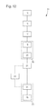
- the invention relates to a method 11 for manufacturing a silicon-based micromechanical component. As illustrated in figure 12 , the method 11 comprises a first step 13 intended to provide a substrate based on silicon.
- the silicon-based terms mean a material comprising monocrystalline silicon, doped monocrystalline silicon, polycrystalline silicon, doped polycrystalline silicon, porous silicon, silicon oxide, quartz, silica, silicon nitride or silicon carbide. Of course, when the silicon-based material is in crystalline phase, any crystalline orientation can be used.
- the substrate 31 based on silicon may be silicon on insulator (also known by the abbreviation "SOI") comprising an upper layer 30 of silicon and a lower layer 34 of silicon connected by an intermediate layer 32 in silicon oxide.
- SOI silicon on insulator
- the substrate could comprise a silicon layer reported on another type of base such as, for example, metal.
- the process is continued with the step 15 intended to form a mask 33 provided with cut-outs 35 on a horizontal part of the substrate 31.
- the mask 33 is formed on the upper part of the upper layer 30 of silicon.
- the mask 33 is formed from a material capable of withstanding the subsequent etching steps of the method 11.
- the mask 33 may be formed from silicon nitride or silicon oxide.
- the mask 33 is formed from silicon oxide.
- the method 11 continues with a step 17 intended to burn, in an etching chamber, in substantially vertical walls 36, in at least a portion of the thickness of the substrate 31 from the perforations 35 of the mask 33 to form peripheral or internal walls of the micromechanical part.
- the step 17 of substantially vertical etching is typically a deep reactive ion etching of the "Bosch" type described above, that is to say by alternating a flow of etching gas and a flow of passivation gas in a chamber etching to form substantially vertical walls 36.
- step 17 allows a substantially vertical direction of etching relative to the mask 33 as visible in FIG. figure 5 .
- This produces an engraving 39 whose section, visible at the figure 5 , is substantially in the form of a right quadrilateral.
- the shape of the volume removed during the etching varies.
- a circular opening will give a cylindrical engraving and a square openwork, a cube or a rectangular parallelepiped.
- step 19 intended to form a protective layer 42 on the vertical walls 36 leaving the bottom 38 of etching 39 without a protective layer as visible in FIG. figure 7 .
- the protective layer 42 is formed of silicon oxide.
- step 19 may then comprise a first phase 18 intended to oxidize the entire top of the substrate 31, that is to say the mask 33 (if formed of silicon oxide), the walls 36 and the bottom 38 formed by the etching 39 to form an extra thickness on the mask 33 and a thickness on the vertical walls 36 and the bottom 38 of the etching 39 to form the protective layer 42 of silicon oxide.
- the second phase 20 could then consist in etching, in a directional manner, the protective layer 42 in order to selectively remove the horizontal silicon oxide surfaces of a portion of the mask 33 and the entire portion of the protective layer 42 only. at the bottom 38 of the engraving 39 as visible at the figure 7 .
- the method 11 can then be continued with the step 21 intended to burn, in the same etching chamber, but according to predetermined oblique walls 37, in the rest of the thickness of the substrate 31 from the bottom 38 without a protective layer. 42 to form oblique lower surfaces under the peripheral walls of the micromechanical part.
- the oblique etching step 21 is not a deep reactive ion etching of the "Bosch" type described above. Indeed, step 21 allows, thanks to the protective layer 42, a much more open angle and a substantially straight direction of etching which avoid being limited by the parameters of a deep reactive ion etching of the "Bosch" type . Indeed, it is generally believed that even changing the parameters of a Deep-type ionic etching of the "Bosch" type, the opening angle can not exceed 10 degrees with a curved engraving direction.
- step 21 is carried out, preferably, by mixing the etching gas SF 6 and the passivation gas C 4 F 8 in the etching chamber in order to form the oblique walls 37. More precisely, the continuous flows of the SF 6 etching and passivation gases C 4 F 8 are pulsed in order to promote etching at the bottom of the cavity.
- step 21 allows a much wider angle typically around 45 degrees in the example of the figure 8 instead of the 10 degrees best obtained by a deep reactive ion etching of the "Bosch" type with an optimized modification of the parameters.
- step 21 thus makes it possible to give a precise opening angle without the surfaces of the vertical walls 36 being modified.
- the angle between the vertical walls 36 and the oblique walls 37 is very reproducible and can be advantageously between substantially 0 ° and substantially 45 °. As explained above, it is especially the possibility of engraving at an angle greater than 10 ° which is remarkable compared to a deep reactive ion etching of the "Bosch" type.
- the angle according to the invention between the vertical walls 36 and the oblique walls 37 is greater than 10 ° and less than 45 °, and even more preferably greater than 20 ° and less than 40 °.
- the pulsation of the continuous flows allows a better etching directivity, or even obtain walls essentially truncated cones, and not spherical (sometimes called isotropic etching) as with wet etching or dry etching as, for example, with SF 6 gas alone.
- a sequence that may comprise a first phase with a stream of SF 6 mixed with a stream of C 4 F 8 during a first duration, followed by a second phase with an increased flux of SF 6 mixed with a decreased flow of C 4 F 8 for a second duration, then again the first and second phases and so on.
- this sequence could comprise a first phase with a flux of SF 6 at 500 SCCM mixed with a flow of C 4 F 8 at 150 SCCM for 1.2 seconds, followed by a second phase represented with a flux of SF 6 at 600 SCCM mixed with a flow of C 4 F 8 at 100 SCCM for 0.8 seconds, followed by a third phase with, again, a flow of SF 6 at 500 SCCM mixed with a flow of C 4 F 8 to 150 SCCM for 1.2 seconds and followed by a fourth phase with a flow of SF 6 at 600 SCCM mixed with a flow of C 4 F 8 at 100 SCCM for 0.8 seconds and so on.
- this pulsation of the continuous flows favors the engraving at the bottom of the cavity which will widen, as and when step 21, the possible opening of the etching 41 as a function of its depth and, incidentally, a opening etching 41 wider at the lower part of the upper layer 30 to start to obtain an etching opening 41 wider than the opening 35 of the mask 33 or the section of the bottom 38 etching 39 early of step 21 as visible during the passage of the figure 7 to the figure 8 .
- step 23 intended to release the micromechanical part of the substrate 31 and the mask 33. More precisely, in the example presented to the figures 9 and 12 step 23 may comprise a deoxidation phase 24 making it possible to remove the mask 33 made of silicon oxide and, optionally, all or part of the intermediate layer 32 made of silicon oxide and then a phase 25 of release of the substrate 31 to the helps, for example, a selective chemical attack.
- the method 11 illustrated in simple line at figure 12 allows, in the same etching chamber, two distinct types of etching.
- the oblique etching of step 21 allows a much more open angle and a direction of substantially straight etching that avoid being limited by the parameters of a deep reactive ion etching of the "Bosch" type and of use the latter, in step 17, according to its optimized parameters of vertical engraving.
- the micromechanical part 51 forming a wheel in the example of the figure 11 has a peripheral wall 54 forming a toothing which has a reduced contact surface.
- the micromechanical part 51 thus comprises a body 61 based on silicon whose peripheral wall 54 borders a horizontal upper surface 53 and a horizontal lower 55 and comprises a first surface 56 substantially vertical and a second oblique surface 57.
- the second oblique surface 57 substantially rectilinear provides the peripheral wall 54 forming toothing, a reduction of the contact surface allowing an improvement in tribology against another room. It is also understood that the inner wall 60 can also more easily receive a member.
- an oxidation step 22 for smoothing the silicon walls can be performed between steps 21 and 23.
- a portion of metal or metal alloy could be deposited in the etching 41, during an optional step between the phases 24 and 25, so as to form a jacket 59 in a hole 60 of the micromechanical part 51 as illustrated at figure 11 .
- This metal or metal alloy portion could even overflow over the etching 41 to form an additional functional level of the composite micromechanical component 51 only formed of metal.
- step 24 deoxidizing the substrate 31 the process 11 could be continued with a step intended to selectively fill a cavity formed during etching 17 and 21 of a metal or a metal alloy in order to offer a fastener to the micromechanical part.
- the lower layer 34 of the substrate 31 could then be heavily doped and used as a direct or indirect basis for an electroplating filling.
- a first phase could be intended to form a mold, for example in photoresist, on the top of the mask 33 and in part of the etching 41.
- a second phase could consist of electroforming a metal part, from the layer 34, at least between the silicon micromechanical part and a part of the mold formed in the etching 41.
- a third phase could consist in removing the mold formed during the first phase. The process would end with the release phase of the composite micromechanical part of the substrate 31 by selective etching.
- the galvanic deposition 59 is, by the shapes of the first substantially vertical surface 56 and a second oblique surface 57, more difficult to remove than with a substantially vertical surface and has a better shear strength.
- said at least one cavity 60 which is at least partially filled with a metal or a metal alloy 59 makes it possible to offer a fastener to the composite micromechanical part 51.
- the cavity 60 could leave a cylindrical recess 62 adapted to allow the composite micromechanical part 51 to be driven onto a shaft with good mechanical strength when the metal or metal alloy part 59 is swept away by the shapes of the peripheral wall 54.
- micromechanical part 51 can not be limited to the application of a wheel as visible in FIG. figure 11 .
- the micromechanical part 51 may form all or part of a movement or dressing member of a timepiece.
- the micromechanical part 51 can thus form all or part of a hairspring, an ankle, a rocker, an axis, a plate, an anchor as an rod, a rod, a fork, a pallet and a dart, a mobile like a wheel, a shaft and a pinion, a bridge, a plate, an oscillating weight, a winding stem , a pad, a case like the middle and horns, a dial, a flange, a bezel, a pusher, a crown, a case back, 'a needle, a bracelet like a link, a decoration, a wall lamp, an ice cream, a clasp, a dial foot, a crown rod or a stem pusher.
Landscapes
- Engineering & Computer Science (AREA)
- Microelectronics & Electronic Packaging (AREA)
- Manufacturing & Machinery (AREA)
- Physics & Mathematics (AREA)
- General Physics & Mathematics (AREA)
- Computer Hardware Design (AREA)
- Chemical & Material Sciences (AREA)
- Analytical Chemistry (AREA)
- Geometry (AREA)
- Metallurgy (AREA)
- Micromachines (AREA)
- Drying Of Semiconductors (AREA)
Abstract
Description
- L'invention se rapporte à une pièce de micromécanique avec une surface de contact diminuée et son procédé de fabrication. Plus particulièrement, l'invention se rapporte à une telle pièce formée par micro-usinage d'une plaquette de matière.
- Le document
CH 698 837 - Un tel micro-usinage est généralement obtenu à partir d'un gravage ionique réactif profond (connu également sous l'abréviation anglaise « DRIE »). Comme illustré aux
figures 1 à 3 , un micro-usinage connu consiste en une structuration d'un masque 1 sur un substrat 3 (cf.Figure 1 , étape A) suivi d'un gravage ionique réactif profond du type « Bosch » combinant successivement une phase d'attaque (cf.figure 1 , étapes B, D, E) suivie d'une phase de passivation (cf.figure 1 , étape C, couche 4) pour obtenir, à partir du motif du masque 1, d'une gravure anisotrope 5, c'est-à-dire sensiblement verticale, dans la plaquette (cf.figure 2 ). - Comme illustré à la
figure 3 , un exemple de gravage ionique réactif profond du type « Bosch » est représenté avec, en trait plein, le flux en SCCM de SF6 en fonction du temps en secondes permettant le gravage d'une plaquette en silicium et, en trait interrompu, le flux en SCCM de C4F8 en fonction du temps en secondes permettant la passivation, c'est-à-dire la protection, de la plaquette en silicium. On peut ainsi très bien voir que les phases sont strictement consécutives et comportent un flux et un temps qui leur sont propres. - Dans l'exemple de la
figure 3 , une première phase G1 de gravage est représentée avec un flux de SF6 à 300 SCCM pendant 7 secondes, suivie par une première phase P1 de passivation avec un flux de C4F8 à 200 SCCM pendant 2 secondes, suivie d'une deuxième phase G2 de gravage avec un flux de SF6 à 300 SCCM à nouveau pendant 7 secondes et, enfin, suivie d'une deuxième phase P2 de passivation avec un flux de C4F8 à 200 SCCM pendant 2 secondes, et ainsi de suite. On remarque donc qu'un certain nombre de paramètres permet de faire varier le gravage ionique réactif profond du type « Bosch » pour avoir une ondulation plus ou moins marquée de la paroi de la gravure verticale 5. - Après plusieurs années de fabrication, il s'est avéré que ces gravures 5 verticales n'étaient pas totalement satisfaisantes notamment au niveau tribologique.
- Le but de la présente invention est de pallier tout ou partie les inconvénients cités précédemment en proposant un nouveau type de pièce de micromécanique et un nouveau type de procédé de fabrication permettant notamment l'amélioration tribologique de pièces formées par micro-usinage d'une plaquette de matière.
- A cet effet, l'invention se rapporte à un procédé de fabrication d'une pièce de micromécanique à base de silicium comportant les étapes suivantes :
- a) se munir d'un substrat à base de silicium ;
- b) former un masque muni d'ajourages sur une partie horizontale du substrat ;
- c) graver, dans une chambre de gravage, selon des parois sensiblement verticales, dans au moins une partie de l'épaisseur du substrat à partir d'ajourages du masque afin de former des parois périphériques de la pièce de micromécanique ;
- d) former une couche de protection sur les parois verticales en laissant le fond de gravure de l'étape c) sans couche de protection ;
- e) graver, dans la chambre de gravage, selon des parois obliques prédéterminées, dans le reste de l'épaisseur du substrat à partir du fond sans couche de protection afin de former des surfaces inférieures obliques sous les parois périphériques de la pièce de micromécanique.
- f) libérer la pièce de micromécanique du masque et du substrat.
- On comprend que, dans la même chambre de gravage, deux types distincts de gravage sont obtenus. On comprend immédiatement que le gravage oblique de l'étape e) permet de former une deuxième surface sensiblement oblique pour former plusieurs pièces de micromécanique sur le même substrat ayant une paroi périphérique à surface de contact réduite. On peut également s'apercevoir que, grâce à la couche de protection uniquement sur les parois verticales, le gravage oblique de l'étape e) autorise un angle largement plus ouvert et une direction de gravure sensiblement rectiligne qui évite d'être limité par les paramètres d'un gravage ionique réactif profond du type « Bosch » qui est, en revanche, utilisé lors de l'étape c) selon ses paramètres optimisés de gravure verticale.
- Conformément à d'autres variantes avantageuses de l'invention :
- l'étape c) est réalisée en alternant un flux de gaz de gravage et un flux de gaz de passivation dans la chambre de gravage afin de former des parois sensiblement verticales ;
- l'étape d) comporte les phases d1) : oxyder la gravure obtenue lors de l'étape c) pour former la couche de protection en oxyde de silicium et d2) : graver de manière directionnelle la couche de protection afin de retirer sélectivement la partie de couche de protection uniquement au niveau du fond de la gravure de l'étape c) ;
- l'étape e) est réalisée en mélangeant du gaz de gravage et du gaz de passivation dans la chambre de gravage afin de former des parois obliques ;
- lors de l'étape e), les flux continus des gaz de gravage et de passivation sont pulsés afin de favoriser le gravage en fond de cavité.
- De plus, l'invention se rapporte à une pièce de micromécanique obtenue à partir du procédé selon l'une des variantes précédentes, caractérisée en ce qu'elle comporte un corps à base de silicium dont la paroi périphérique comporte une première surface sensiblement verticale et une deuxième surface oblique permettant de diminuer la surface de contact de la paroi périphérique.
- Avantageusement selon l'invention, on comprend que la paroi périphérique ou interne verticale de la pièce de micromécanique offre une réduction de sa surface de contact ou quant à l'entrée d'un organe le long d'une paroi interne de la pièce de micromécanique permettant d'apporter une amélioration quant à la tribologie contre une autre pièce.
- Conformément à d'autres variantes avantageuses de l'invention :
- la pièce de micromécanique comporte en outre au moins une cavité comportant une paroi interne comprenant également une première surface sensiblement verticale et une deuxième surface sensiblement oblique ;
- la pièce de micromécanique forme tout ou partie d'un organe de mouvement ou d'habillage d'une pièce d'horlogerie.
- D'autres particularités et avantages ressortiront clairement de la description qui en est faite ci-après, à titre indicatif et nullement limitatif, en référence aux dessins annexés, dans lesquels :
- les
figures 1 à 3 sont des représentations destinées à expliquer le gravage ionique réactif profond du type « Bosch » utilisé dans le cadre de l'invention ; - les
figures 4 à 10 sont des représentations d'étapes de fabrication d'une pièce de micromécanique de l'invention ; - la
figure 11 est une représentation d'une pièce de micromécanique selon l'invention ; - la
figure 12 est un schéma fonctionnel du procédé de fabrication selon l'invention. - L'invention se rapporte à un procédé 11 de fabrication d'une pièce de micromécanique à base de silicium. Comme illustré à la
figure 12 , le procédé 11 comporte une première étape 13 destinée à se munir d'un substrat à base de silicium. - Les termes à base de silicium signifient un matériau comportant du silicium monocristallin, du silicium monocristallin dopé, du silicium polycristallin, du silicium polycristallin dopé, du silicium poreux, de l'oxyde de silicium, du quartz, de la silice, du nitrure de silicium ou du carbure de silicium. Bien entendu, quand le matériau à base de silicium est sous phase cristalline, n'importe quelle orientation cristalline peut être utilisée.
- Typiquement, comme illustré à la
figure 4 , le substrat 31 à base de silicium peut être du silicium sur isolant (également connu sous l'abréviation anglaise « SOI ») comportant une couche supérieure 30 en silicium et une couche inférieure 34 en silicium reliées par une couche intermédiaire 32 en oxyde de silicium. Toutefois, alternativement, le substrat pourrait comporter une couche de silicium rapportée sur une autre type de base comme, par exemple, en métal. - Le procédé se poursuit avec l'étape 15 destinée à former un masque 33 muni d'ajourages 35 sur une partie horizontale du substrat 31. Dans l'exemple de la
figure 4 , le masque 33 est formé sur la partie supérieure de la couche supérieure 30 en silicium. Le masque 33 est formé à partir d'un matériau capable de résister aux futures étapes de gravage du procédé 11. A ce titre, le masque 33 peut être formé à partir de nitrure de silicium ou d'oxyde de silicium. Dans l'exemple de lafigure 4 , le masque 33 est formé à partir d'oxyde de silicium. - Avantageusement selon l'invention, le procédé 11 se poursuit avec une étape 17 destinée à graver, dans une chambre de gravage, selon des parois 36 sensiblement verticales, dans au moins une partie de l'épaisseur du substrat 31 à partir des ajourages 35 du masque 33 afin de former des parois périphériques ou internes de la pièce de micromécanique.
- L'étape 17 de gravage sensiblement vertical est typiquement un gravage ionique réactif profond du type « Bosch » décrit ci-dessus, c'est-à-dire en alternant un flux de gaz de gravage et un flux de gaz de passivation dans une chambre de gravage afin de former des parois sensiblement verticales 36.
- En effet, l'étape 17 autorise une direction de gravure sensiblement verticale par rapport au masque 33 comme visible à la
figure 5 . On obtient ainsi une gravure 39 dont la section, visible à lafigure 5 , est sensiblement sous forme d'un quadrilatère droit. Bien entendu, suivant la forme des ajourages 35, la forme du volume enlevé lors du gravage varie. Ainsi, un ajourage circulaire donnera une gravure cylindrique et un ajourage carré, un cube ou un parallélépipède rectangle. - Le procédé 11 se poursuit avec l'étape 19 destinée à former une couche de protection 42 sur les parois verticales 36 en laissant le fond 38 de gravure 39 sans couche de protection comme visible à la
figure 7 . - Préférentiellement, la couche de protection 42 est formée en oxyde de silicium. En effet, comme visible aux
figures 6 et 7 , l'étape 19 peut alors comporter une première phase 18 destinée à oxyder tout le dessus du substrat 31, c'est-à-dire le masque 33 (si formé en oxyde de silicium), les parois 36 et le fond 38 formés par la gravure 39 pour former une surépaisseur sur le masque 33 et une épaisseur sur les parois verticales 36 et le fond 38 de la gravure 39 pour former la couche de protection 42 en oxyde de silicium. - La deuxième phase 20 pourrait alors consister à graver, de manière directionnelle, la couche de protection 42 afin de retirer sélectivement les surfaces horizontales en oxyde de silicium d'une partie du masque 33 et de la totalité de la partie de couche de protection 42 uniquement au niveau du fond 38 de la gravure 39 comme visible à la
figure 7 . - Le procédé 11 peut alors se poursuivre avec l'étape 21 destinée à graver, dans la même chambre de gravage, mais selon des parois obliques 37 prédéterminées, dans le reste de l'épaisseur du substrat 31 à partir du fond 38 sans couche de protection 42 afin de former des surfaces inférieures obliques sous les parois périphériques de la pièce de micromécanique.
- L'étape 21 de gravage oblique n'est pas un gravage ionique réactif profond du type « Bosch » décrit ci-dessus. En effet, l'étape 21 autorise, grâce à la couche de protection 42, un angle largement plus ouvert et une direction de gravure sensiblement rectiligne qui évitent d'être limités par les paramètres d'un gravage ionique réactif profond du type « Bosch ». En effet, on estime généralement que, même en modifiant les paramètres d'un gravage ionique réactif profond du type « Bosch », l'angle d'ouverture ne peut excéder 10 degrés en ayant une direction de gravure courbe.
- Avantageusement selon l'invention, l'étape 21 est réalisée, préférentiellement, en mélangeant du gaz SF6 de gravage et du gaz C4F8 de passivation dans la chambre de gravage afin de former les parois 37 obliques. Plus précisément, les flux continus des gaz SF6 de gravage et de passivation C4F8 sont pulsés afin de favoriser le gravage en fond de cavité.
- On comprend donc l'étape 21 autorise un angle largement plus ouvert typiquement autour de 45 degrés dans l'exemple de la
figure 8 au lieu des 10 degrés obtenus au mieux par un gravage ionique réactif profond du type « Bosch » avec une modification optimisée des paramètres. Avantageusement selon l'invention, l'étape 21 permet ainsi de donner un angle d'ouverture précis sans que les surfaces des parois verticales 36 ne soient modifiées. L'angle entre les parois verticales 36 et les parois obliques 37 est très reproductible et peut être avantageusement compris entre sensiblement 0° et sensiblement 45°. Comme expliqué ci-dessus, c'est surtout la possibilité de graver selon un angle supérieur à 10° qui est remarquable par rapport à un gravage ionique réactif profond du type « Bosch ». Préférentiellement, l'angle selon l'invention entre les parois verticales 36 et les parois obliques 37 est supérieur à 10° et inférieur à 45°, et encore plus préféré, supérieur à 20° et inférieur à 40°. - De plus, la pulsation des flux continus autorise une meilleure directivité de gravure, voire obtenir des parois essentiellement en tronc de cônes, et non sphériques (parfois appelés gravures isotropes) comme avec un gravage humide ou un gravage sec comme, par exemple, avec du gaz SF6 seul.
- Pour obtenir la forme de parois 37 de la
figure 8 , on peut par exemple appliquer une séquence pouvant comporter une première phase avec un flux de SF6 mélangé avec un flux de C4F8 pendant une première durée, suivie par une deuxième phase avec un flux augmenté de SF6 mélangé avec un flux diminué de C4F8 pendant une deuxième durée, puis à nouveau les première et deuxième phases et ainsi de suite. - A titre d'exemple, cette séquence pourrait comporter une première phase avec un flux de SF6 à 500 SCCM mélangé avec un flux de C4F8 à 150 SCCM pendant 1,2 seconde, suivie par une deuxième phase représentée avec un flux de SF6 à 600 SCCM mélangé avec un flux de C4F8 à 100 SCCM pendant 0,8 seconde, suivie d'une troisième phase avec, à nouveau, un flux de SF6 à 500 SCCM mélangé avec un flux de C4F8 à 150 SCCM pendant 1,2 seconde et suivie d'une quatrième phase avec un flux de SF6 à 600 SCCM mélangé avec un flux de C4F8 à 100 SCCM pendant 0,8 seconde et ainsi de suite.
- On remarque donc que cette pulsation des flux continus favorise le gravage en fond de cavité ce qui va élargir, au fur et à mesure de l'étape 21, l'ouverture possible de la gravure 41 en fonction de sa profondeur et, incidemment, une ouverture de gravure 41 plus large au niveau de la partie inférieure de la couche supérieure 30 jusqu'à commencer à obtenir une ouverture de gravure 41 plus large que l'ajourage 35 du masque 33 ou de la section du fond 38 de gravure 39 en début d'étape 21 comme visible lors du passage de la
figure 7 à lafigure 8 . - Le procédé 11 se finit avec l'étape 23 destinée à libérer la pièce de micromécanique du substrat 31 et du masque 33. Plus précisément, dans l'exemple présenté aux
figures 9 et12 , l'étape 23 peut comporter une phase 24 de désoxydation permettant de retirer le masque 33 en oxyde de silicium et, éventuellement, tout ou partie de la couche intermédiaire 32 en oxyde de silicium puis une phase 25 de libération du substrat 31 à l'aide, par exemple, d'une attaque chimique sélective. - Le procédé 11 illustré en trait simple à la
figure 12 permet, dans une même chambre de gravage, deux types distincts de gravage. On peut également s'apercevoir que le gravage oblique de l'étape 21 autorise un angle largement plus ouvert et une direction de gravure sensiblement rectiligne qui évitent d'être limités par les paramètres d'un gravage ionique réactif profond du type « Bosch » et d'utiliser ce dernier, lors de l'étape 17, selon ses paramètres optimisés de gravure verticale. - Avantageusement selon l'invention, la pièce de micromécanique 51 formant une roue dans l'exemple de la
figure 11 comporte une paroi périphérique 54 formant une denture qui comporte une surface de contact réduite. - Comme mieux visible à la
figure 10 qui est une vue agrandie sur une partie de la pièce 51, la pièce de micromécanique 51 comporte ainsi un corps 61 à base de silicium dont la paroi périphérique 54 borde une surface supérieure horizontale 53 et une inférieure horizontale 55 et comporte une première surface 56 sensiblement verticale et une deuxième surface 57 oblique. - On comprend donc que la deuxième surface oblique 57 sensiblement rectiligne apporte à la paroi périphérique 54 formant denture, une diminution de la surface de contact permettant une amélioration quant à sa tribologie contre une autre pièce. On comprend également que la paroi interne 60 peut également recevoir plus facilement un organe.
- Bien entendu, la présente invention ne se limite pas à l'exemple illustré mais est susceptible de diverses variantes et modifications qui apparaîtront à l'homme de l'art. En particulier, une étape d'oxydation 22 destinée à lisser les parois en silicium peut être exécutée entre les étapes 21 et 23.
- De plus, une partie en métal ou en alliage métallique pourrait être déposée dans la gravure 41, lors d'une étape optionnelle entre les phases 24 et 25, de sorte à former une chemise 59 dans un trou 60 de la pièce de micromécanique 51 comme illustré à la
figure 11 . - Cette partie en métal ou en alliage métallique pourrait même déborder au-dessus de la gravure 41 afin de former un niveau fonctionnel supplémentaire de la pièce de micromécanique composite 51 uniquement formé en métal.
- Ainsi, après l'étape 24 désoxydant le substrat 31, le procédé 11, pourrait se poursuivre avec une étape destinée à remplir sélectivement une cavité formée lors des gravages 17 et 21, d'un métal ou d'un alliage métallique afin d'offrir une attache à la pièce de micromécanique.
- A titre d'exemple, préférentiellement, la couche inférieure 34 du substrat 31 pourrait alors être fortement dopée et utilisée comme base directe ou indirecte pour un remplissage par galvanoplastie. Ainsi, une première phase pourrait être destinée à former un moule, par exemple en résine photosensible, sur le dessus du masque 33 et dans une partie de la gravure 41. Une deuxième phase pourrait consister à électroformer une partie métallique, à partir de la couche inférieure 34, au moins entre la pièce de micromécanique en silicium et une partie du moule formé dans la gravure 41. Enfin, une troisième phase pourrait consister à retirer le moule formé lors de la première phase. Le procédé se finirait avec la phase 25 de libération de la pièce de micromécanique composite du substrat 31 par une attaque chimique sélective.
- Avantageusement selon l'invention, on comprend alors que le dépôt galvanique 59 est, par les formes de la première surface sensiblement verticale 56 et une deuxième surface oblique 57, plus difficile à retirer qu'avec une surface essentiellement verticale et bénéficie d'une meilleure résistance au cisaillement.
- De plus, ladite au moins une cavité 60 qui est au moins partiellement remplie d'un métal ou d'un alliage métallique 59 permet d'offrir une attache à la pièce de micromécanique composite 51. Ainsi, dans l'exemple de la
figure 11 , la cavité 60 pourrait laisser un évidement cylindrique 62 apte à permettre le chassage de la pièce de micromécanique composite 51 sur un arbre avec une bonne résistance mécanique lors du dudgeonnage de la partie en métal ou en alliage métallique 59 grâce aux formes de la paroi périphérique 54. - Enfin, la pièce de micromécanique 51 ne saurait se limiter à l'application d'une roue comme visible à la
figure 11 . Ainsi, la pièce de micromécanique 51 peut former tout ou partie d'un organe de mouvement ou d'habillage d'une pièce d'horlogerie. - A titre d'exemples nullement limitatifs, la pièce de micromécanique 51 peut ainsi former tout ou partie d'un spiral, d'une cheville, d'un balancier, d'un axe, d'un plateau, d'une ancre comme une tige, une baguette, une fourchette, une palette et un dard, d'un mobile comme une roue, un arbre et un pignon, d'un pont, d'une platine, d'une masse oscillante, d'une tige de remontoir, d'un coussinet, d'un boîtier comme la carrure et les cornes, d'un cadran, d'un réhaut, d'une lunette, d'un poussoir, d'une couronne, d'un fond de boîtier, d'une aiguille, d'un bracelet comme un maillon, d'un décor, d'une applique, d'une glace, d'un fermoir, d'un pied de cadran, d'une tige de couronne ou d'une tige de poussoir.
Claims (8)
- Procédé (11) de fabrication d'une pièce de micromécanique (51) à base de silicium comportant les étapes suivantes :a) se munir d'un substrat (30) à base de silicium ;b) former un masque (33) muni d'ajourages (35) sur une partie horizontale du substrat (30) ;c) graver, dans une chambre de gravage, selon des parois (36) sensiblement verticales, dans une partie de l'épaisseur du substrat (30), à partir d'ajourages (35) du masque (33), afin de former des parois périphériques (56) de la pièce de micromécanique (51) ;d) former une couche (42) de protection sur les parois (36) verticales en laissant le fond (38) de gravure (39) de l'étape c) sans couche de protection ;e) graver, dans la chambre de gravage, selon des parois (37) obliques prédéterminées, dans le reste de l'épaisseur du substrat (30) à partir du fond (38) sans couche de protection afin de former des surfaces inférieures (57) obliques sous les parois périphériques (56) de la pièce de micromécanique.f) libérer la pièce de micromécanique (51) du masque (33) et du substrat (30).
- Procédé selon la revendication précédente, caractérisé en ce que l'étape c) est réalisée en alternant un flux de gaz de gravage et un flux de gaz de passivation dans la chambre de gravage afin de former des parois (36) sensiblement verticales.
- Procédé selon la revendication 1 ou 2, caractérisé en ce que l'étape d) comporte les phases suivantes :d1) oxyder la gravure (39) obtenue lors de l'étape c) pour former la couche (42) de protection en oxyde de silicium ;d2) graver de manière directionnelle la couche (42) de protection afin de retirer sélectivement la partie de couche (42) de protection uniquement au niveau du fond (38) de la gravure (39) de l'étape c).
- Procédé selon l'une des revendications précédentes, caractérisé en ce que l'étape e) est réalisée en mélangeant du gaz de gravage et du gaz de passivation dans la chambre de gravage afin de former des parois (37) obliques.
- Procédé selon la revendication précédente, caractérisé en ce que, lors de l'étape e), les flux continus des gaz de gravage et de passivation sont pulsés afin de favoriser le gravage en fond de cavité.
- Pièce de micromécanique (51) obtenue à partir du procédé selon l'une des revendications précédentes, caractérisée en ce qu'elle comporte un corps (61) à base de silicium dont la paroi périphérique (54) comporte une première surface (56) sensiblement verticale et une deuxième surface (57) oblique permettant de diminuer la surface de contact de la paroi périphérique (54).
- Pièce de micromécanique (51) selon la revendication précédente, caractérisée en ce qu'elle comporte, en outre, au moins une cavité (60) comportant une paroi interne comprenant également une première surface (56) sensiblement verticale et une deuxième surface (57) sensiblement oblique.
- Pièce de micromécanique (51) selon la revendication 6 ou 7, caractérisé en ce qu'elle forme tout ou partie d'un organe de mouvement ou d'habillage d'une pièce d'horlogerie.
Applications Claiming Priority (1)
| Application Number | Priority Date | Filing Date | Title |
|---|---|---|---|
| EP15173825 | 2015-06-25 |
Publications (2)
| Publication Number | Publication Date |
|---|---|
| EP3109200A1 true EP3109200A1 (fr) | 2016-12-28 |
| EP3109200B1 EP3109200B1 (fr) | 2023-06-28 |
Family
ID=53496484
Family Applications (1)
| Application Number | Title | Priority Date | Filing Date |
|---|---|---|---|
| EP16170650.2A Active EP3109200B1 (fr) | 2015-06-25 | 2016-05-20 | Piece de micromecanique avec une surface de contact diminuee et son procede de fabrication |
Country Status (6)
| Country | Link |
|---|---|
| US (1) | US9731964B2 (fr) |
| EP (1) | EP3109200B1 (fr) |
| JP (1) | JP6177390B2 (fr) |
| CN (1) | CN106276772B (fr) |
| RU (1) | RU2707712C1 (fr) |
| TW (1) | TWI681924B (fr) |
Cited By (4)
| Publication number | Priority date | Publication date | Assignee | Title |
|---|---|---|---|---|
| WO2019043432A1 (fr) * | 2017-08-30 | 2019-03-07 | Ecole Polytechnique Federale De Lausanne (Epfl) | Procédé de production de pièce en diamant monocristallin pour la production d'un composant mécanique et optique monocristallin autonome |
| WO2019155347A1 (fr) | 2018-02-07 | 2019-08-15 | Patek Philippe Sa Geneve | Pièce de micromécanique horlogère |
| EP3608727A1 (fr) * | 2018-08-09 | 2020-02-12 | Nivarox-FAR S.A. | Composant notamment horloger avec une topologie de surface et son procédé de fabrication |
| EP3742237A1 (fr) * | 2019-05-23 | 2020-11-25 | Nivarox-FAR S.A. | Composant notamment horloger avec une topologie de surface et son procede de fabrication |
Families Citing this family (7)
| Publication number | Priority date | Publication date | Assignee | Title |
|---|---|---|---|---|
| CN107934905B (zh) * | 2017-11-24 | 2020-02-28 | 中国矿业大学 | 一种微机电系统的运动部件及其加工方法 |
| EP3543795A1 (fr) * | 2018-03-20 | 2019-09-25 | Patek Philippe SA Genève | Procede de fabrication de composants horlogers en silicium |
| CN109218945A (zh) * | 2018-08-07 | 2019-01-15 | 瑞声科技(新加坡)有限公司 | Mems结构的制造方法、mems结构及硅麦克风 |
| CN112028012A (zh) * | 2019-11-21 | 2020-12-04 | 中芯集成电路(宁波)有限公司 | 一种半导体芯片的制造方法 |
| EP3882710A1 (fr) * | 2020-03-19 | 2021-09-22 | Patek Philippe SA Genève | Procédé de fabrication d'un composant horloger à base de silicium |
| CN111540824B (zh) * | 2020-05-09 | 2023-04-18 | 中国科学院微电子研究所 | 热电堆及其制作方法 |
| US11712766B2 (en) * | 2020-05-28 | 2023-08-01 | Toyota Motor Engineering And Manufacturing North America, Inc. | Method of fabricating a microscale canopy wick structure having enhanced capillary pressure and permeability |
Citations (6)
| Publication number | Priority date | Publication date | Assignee | Title |
|---|---|---|---|---|
| US6150275A (en) * | 1998-04-01 | 2000-11-21 | Cho; Dong-Il | Micromechanical system fabrication method using (111) single crystalline silicon |
| US6406636B1 (en) * | 1999-06-02 | 2002-06-18 | Megasense, Inc. | Methods for wafer to wafer bonding using microstructures |
| CH698837B1 (fr) | 2003-02-06 | 2009-11-13 | Eta Sa Mft Horlogere Suisse | Spiral de résonateur balancier-spiral et son procédé de fabrication. |
| CH699476A2 (fr) * | 2008-08-29 | 2010-03-15 | Patek Philippe Sa Geneve | Procédé de fabrication d'un composant horloger en silicium. |
| EP2735540A1 (fr) * | 2012-11-22 | 2014-05-28 | Diamaze Microtechnology S.A. | Composant micromécanique composite ayant un revêtement, son procédé de fabrication et son utilisation |
| EP2840059A1 (fr) * | 2013-08-20 | 2015-02-25 | Sigatec SA | Procédé de fabrication d une pièce de micro-mécanique et la pièce fabriquée à l'aide de ce procédé |
Family Cites Families (20)
| Publication number | Priority date | Publication date | Assignee | Title |
|---|---|---|---|---|
| US6573154B1 (en) * | 2000-10-26 | 2003-06-03 | Institute Of Microelectronics | High aspect ratio trench isolation process for surface micromachined sensors and actuators |
| US6618519B2 (en) * | 2001-07-16 | 2003-09-09 | Chromux Technologies, Inc. | Switch and variable optical attenuator for single or arrayed optical channels |
| FR2828185A1 (fr) * | 2001-07-31 | 2003-02-07 | Memscap | Procede de fabrication d'un composant optique microelectromecanique |
| JP4696533B2 (ja) * | 2003-12-16 | 2011-06-08 | セイコーエプソン株式会社 | 装飾部品、装飾部品の製造方法、シート状シール、時計、および被装飾部品 |
| JP2005272867A (ja) * | 2004-03-23 | 2005-10-06 | Alps Electric Co Ltd | 金型作製方法 |
| MXPA06012211A (es) * | 2004-04-21 | 2007-01-31 | Federal Mogul Corp | Metodo y aparato para cierre de placa de cubierta de ajuste de separacion. |
| US20050247894A1 (en) * | 2004-05-05 | 2005-11-10 | Watkins Charles M | Systems and methods for forming apertures in microfeature workpieces |
| CH714952B1 (fr) * | 2007-05-08 | 2019-10-31 | Patek Philippe Sa Geneve | Composant horloger, son procédé de fabrication et application de ce procédé. |
| EP2120105A1 (fr) * | 2008-05-13 | 2009-11-18 | Sigatec SA | Pièce micromécanique améliorée comportant des éléments de lubrification |
| CN101559916B (zh) * | 2009-04-28 | 2011-07-27 | 北京大学 | 一种掩蔽微结构的制备方法 |
| CH704256A2 (fr) * | 2010-12-22 | 2012-06-29 | Eta Sa Mft Horlogere Suisse | Assemblage d'une pièce ne comportant pas de domaine plastique. |
| EP2469351A1 (fr) * | 2010-12-22 | 2012-06-27 | Nivarox-FAR S.A. | Assemblage d'une pièce ne comportant pas de domaine plastique |
| DE102011079373A1 (de) * | 2011-07-19 | 2013-01-24 | Robert Bosch Gmbh | Schaltungsträger mit einem Kontaktelement |
| CN102285637A (zh) * | 2011-09-14 | 2011-12-21 | 上海先进半导体制造股份有限公司 | 带侧壁保护的腔体制造方法 |
| CN103035561B (zh) * | 2012-08-31 | 2015-04-08 | 上海华虹宏力半导体制造有限公司 | 深沟槽顶部倾斜角形成的工艺方法 |
| CN102838079B (zh) * | 2012-09-24 | 2015-04-22 | 江苏物联网研究发展中心 | 用于传感器芯片的开放式封装结构及其制造方法 |
| JP5725052B2 (ja) * | 2013-02-01 | 2015-05-27 | セイコーエプソン株式会社 | ノズルプレートの製造方法及び流体噴射ヘッドの製造方法 |
| FR3006304B1 (fr) * | 2013-05-28 | 2015-07-03 | Commissariat Energie Atomique | Procede de realisation d'une partie suspendue d'une structure microelectronique et/ou nanoelectronique dans une partie monolithique d'un substrat |
| CN103456620B (zh) * | 2013-09-11 | 2016-03-02 | 中微半导体设备(上海)有限公司 | 半导体结构的形成方法 |
| JP2016138834A (ja) * | 2015-01-28 | 2016-08-04 | シチズンホールディングス株式会社 | 構造体及びその製造方法 |
-
2016
- 2016-05-20 EP EP16170650.2A patent/EP3109200B1/fr active Active
- 2016-05-30 TW TW105116877A patent/TWI681924B/zh active
- 2016-06-02 US US15/171,002 patent/US9731964B2/en active Active
- 2016-06-21 JP JP2016122395A patent/JP6177390B2/ja active Active
- 2016-06-23 CN CN201610465132.0A patent/CN106276772B/zh active Active
- 2016-06-24 RU RU2016125427A patent/RU2707712C1/ru active
Patent Citations (6)
| Publication number | Priority date | Publication date | Assignee | Title |
|---|---|---|---|---|
| US6150275A (en) * | 1998-04-01 | 2000-11-21 | Cho; Dong-Il | Micromechanical system fabrication method using (111) single crystalline silicon |
| US6406636B1 (en) * | 1999-06-02 | 2002-06-18 | Megasense, Inc. | Methods for wafer to wafer bonding using microstructures |
| CH698837B1 (fr) | 2003-02-06 | 2009-11-13 | Eta Sa Mft Horlogere Suisse | Spiral de résonateur balancier-spiral et son procédé de fabrication. |
| CH699476A2 (fr) * | 2008-08-29 | 2010-03-15 | Patek Philippe Sa Geneve | Procédé de fabrication d'un composant horloger en silicium. |
| EP2735540A1 (fr) * | 2012-11-22 | 2014-05-28 | Diamaze Microtechnology S.A. | Composant micromécanique composite ayant un revêtement, son procédé de fabrication et son utilisation |
| EP2840059A1 (fr) * | 2013-08-20 | 2015-02-25 | Sigatec SA | Procédé de fabrication d une pièce de micro-mécanique et la pièce fabriquée à l'aide de ce procédé |
Cited By (8)
| Publication number | Priority date | Publication date | Assignee | Title |
|---|---|---|---|---|
| WO2019043432A1 (fr) * | 2017-08-30 | 2019-03-07 | Ecole Polytechnique Federale De Lausanne (Epfl) | Procédé de production de pièce en diamant monocristallin pour la production d'un composant mécanique et optique monocristallin autonome |
| US11512409B2 (en) | 2017-08-30 | 2022-11-29 | Ecole Polytechnique Federale De Lausanne | Single crystalline diamond part production method for stand alone single crystalline mechanical and optical component production |
| WO2019155347A1 (fr) | 2018-02-07 | 2019-08-15 | Patek Philippe Sa Geneve | Pièce de micromécanique horlogère |
| US11829107B2 (en) | 2018-02-07 | 2023-11-28 | Patek Philippe Sa Geneve | Micro-mechanical timepiece part |
| EP3608727A1 (fr) * | 2018-08-09 | 2020-02-12 | Nivarox-FAR S.A. | Composant notamment horloger avec une topologie de surface et son procédé de fabrication |
| US10981783B2 (en) | 2018-08-09 | 2021-04-20 | Nivarox-Far S.A. | Component especially for horology with surface topology and method for manufacturing the same |
| EP3742237A1 (fr) * | 2019-05-23 | 2020-11-25 | Nivarox-FAR S.A. | Composant notamment horloger avec une topologie de surface et son procede de fabrication |
| US11586145B2 (en) | 2019-05-23 | 2023-02-21 | Nivarox-Far S.A. | Component especially for horology with surface topology and method for manufacturing the same |
Also Published As
| Publication number | Publication date |
|---|---|
| CN106276772B (zh) | 2019-06-14 |
| US20160376147A1 (en) | 2016-12-29 |
| RU2707712C1 (ru) | 2019-11-28 |
| CN106276772A (zh) | 2017-01-04 |
| US9731964B2 (en) | 2017-08-15 |
| JP2017009609A (ja) | 2017-01-12 |
| RU2016125427A (ru) | 2017-12-26 |
| JP6177390B2 (ja) | 2017-08-09 |
| TWI681924B (zh) | 2020-01-11 |
| EP3109200B1 (fr) | 2023-06-28 |
| TW201716315A (zh) | 2017-05-16 |
Similar Documents
| Publication | Publication Date | Title |
|---|---|---|
| EP3109200B1 (fr) | Piece de micromecanique avec une surface de contact diminuee et son procede de fabrication | |
| EP3109199B1 (fr) | Piece a base de silicium avec au moins un chanfrein et son procede de fabrication | |
| EP2105807B1 (fr) | Spiral à élévation de courbe monobloc et son procédé de fabrication | |
| EP2628607B1 (fr) | Dispositif d'ancrage d'une incrustation métallique | |
| EP2767870B1 (fr) | Procédé de fabrication d'une pièce de micromécanique monobloc comportant au moins deux niveaux fonctionnels distincts | |
| EP2230208B1 (fr) | Moule pour galvanoplastie et son procédé de fabrication | |
| EP3066044B1 (fr) | Pièce de micromécanique creuse, à plusieurs niveaux fonctionnels et monobloc en un matériau à base d'un allotrope synthétique du carbone | |
| EP2261171A1 (fr) | Pièce de micromécanique composite et son procédé de fabrication | |
| CH711247A2 (fr) | Pièce de micromécanique avec une surface de contact diminuée et son procédé de fabrication. | |
| EP3622846A1 (fr) | Procede d'assemblage d'au moins deux elements | |
| CH711248B1 (fr) | Pièce à base de silicium avec au moins un chanfrein et son procédé de fabrication. | |
| EP3168697B1 (fr) | Procédé de fabrication d'une pièce à base de silicium avec au moins un motif à illusion d'optique | |
| CH701266A2 (fr) | Pièce de micromécanique composite et son procédé de fabrication. | |
| EP2881808B1 (fr) | Procédé de fabrication d'un composant horloger | |
| CH715191A2 (fr) | Procédé de décoration d'un composant d'habillage en horlogerie. | |
| CH711740A2 (fr) | Procédé de fabrication d'une pièce à base de silicium avec au moins un motif à illusion d'optique. | |
| HK1232513B (zh) | 具有至少一个斜面的硅基部件及其制造方法 | |
| HK1232512B (zh) | 具有减少的接触面的微机械部件及其制造方法 | |
| CH707562B1 (fr) | Procédé de fabrication d'une pièce de micromécanique monobloc comportant au moins deux niveaux distincts. | |
| HK1232513A1 (en) | Silicon-based component with at least one chamfer and its fabrication method | |
| CH700554A2 (fr) | Moule pour galvanoplastie et son procédé de fabrication. |
Legal Events
| Date | Code | Title | Description |
|---|---|---|---|
| PUAI | Public reference made under article 153(3) epc to a published international application that has entered the european phase |
Free format text: ORIGINAL CODE: 0009012 |
|
| STAA | Information on the status of an ep patent application or granted ep patent |
Free format text: STATUS: THE APPLICATION HAS BEEN PUBLISHED |
|
| AK | Designated contracting states |
Kind code of ref document: A1 Designated state(s): AL AT BE BG CH CY CZ DE DK EE ES FI FR GB GR HR HU IE IS IT LI LT LU LV MC MK MT NL NO PL PT RO RS SE SI SK SM TR |
|
| AX | Request for extension of the european patent |
Extension state: BA ME |
|
| STAA | Information on the status of an ep patent application or granted ep patent |
Free format text: STATUS: REQUEST FOR EXAMINATION WAS MADE |
|
| 17P | Request for examination filed |
Effective date: 20170628 |
|
| RBV | Designated contracting states (corrected) |
Designated state(s): AL AT BE BG CH CY CZ DE DK EE ES FI FR GB GR HR HU IE IS IT LI LT LU LV MC MK MT NL NO PL PT RO RS SE SI SK SM TR |
|
| STAA | Information on the status of an ep patent application or granted ep patent |
Free format text: STATUS: EXAMINATION IS IN PROGRESS |
|
| 17Q | First examination report despatched |
Effective date: 20200624 |
|
| REG | Reference to a national code |
Ref country code: DE Ref legal event code: R079 Ref document number: 602016080579 Country of ref document: DE Free format text: PREVIOUS MAIN CLASS: B81C0099000000 Ipc: G04B0013020000 Ref country code: DE Ref legal event code: R079 Free format text: PREVIOUS MAIN CLASS: B81C0099000000 Ipc: G04B0013020000 |
|
| RIC1 | Information provided on ipc code assigned before grant |
Ipc: G04B 13/02 20060101AFI20221223BHEP |
|
| GRAP | Despatch of communication of intention to grant a patent |
Free format text: ORIGINAL CODE: EPIDOSNIGR1 |
|
| STAA | Information on the status of an ep patent application or granted ep patent |
Free format text: STATUS: GRANT OF PATENT IS INTENDED |
|
| INTG | Intention to grant announced |
Effective date: 20230301 |
|
| GRAS | Grant fee paid |
Free format text: ORIGINAL CODE: EPIDOSNIGR3 |
|
| GRAA | (expected) grant |
Free format text: ORIGINAL CODE: 0009210 |
|
| STAA | Information on the status of an ep patent application or granted ep patent |
Free format text: STATUS: THE PATENT HAS BEEN GRANTED |
|
| AK | Designated contracting states |
Kind code of ref document: B1 Designated state(s): AL AT BE BG CH CY CZ DE DK EE ES FI FR GB GR HR HU IE IS IT LI LT LU LV MC MK MT NL NO PL PT RO RS SE SI SK SM TR |
|
| REG | Reference to a national code |
Ref country code: CH Ref legal event code: EP |
|
| REG | Reference to a national code |
Ref country code: AT Ref legal event code: REF Ref document number: 1583244 Country of ref document: AT Kind code of ref document: T Effective date: 20230715 |
|
| P01 | Opt-out of the competence of the unified patent court (upc) registered |
Effective date: 20230611 |
|
| REG | Reference to a national code |
Ref country code: IE Ref legal event code: FG4D Free format text: LANGUAGE OF EP DOCUMENT: FRENCH |
|
| REG | Reference to a national code |
Ref country code: DE Ref legal event code: R096 Ref document number: 602016080579 Country of ref document: DE |
|
| REG | Reference to a national code |
Ref country code: LT Ref legal event code: MG9D |
|
| PG25 | Lapsed in a contracting state [announced via postgrant information from national office to epo] |
Ref country code: SE Free format text: LAPSE BECAUSE OF FAILURE TO SUBMIT A TRANSLATION OF THE DESCRIPTION OR TO PAY THE FEE WITHIN THE PRESCRIBED TIME-LIMIT Effective date: 20230628 Ref country code: NO Free format text: LAPSE BECAUSE OF FAILURE TO SUBMIT A TRANSLATION OF THE DESCRIPTION OR TO PAY THE FEE WITHIN THE PRESCRIBED TIME-LIMIT Effective date: 20230928 |
|
| REG | Reference to a national code |
Ref country code: NL Ref legal event code: MP Effective date: 20230628 |
|
| REG | Reference to a national code |
Ref country code: AT Ref legal event code: MK05 Ref document number: 1583244 Country of ref document: AT Kind code of ref document: T Effective date: 20230628 |
|
| PG25 | Lapsed in a contracting state [announced via postgrant information from national office to epo] |
Ref country code: RS Free format text: LAPSE BECAUSE OF FAILURE TO SUBMIT A TRANSLATION OF THE DESCRIPTION OR TO PAY THE FEE WITHIN THE PRESCRIBED TIME-LIMIT Effective date: 20230628 Ref country code: NL Free format text: LAPSE BECAUSE OF FAILURE TO SUBMIT A TRANSLATION OF THE DESCRIPTION OR TO PAY THE FEE WITHIN THE PRESCRIBED TIME-LIMIT Effective date: 20230628 Ref country code: LV Free format text: LAPSE BECAUSE OF FAILURE TO SUBMIT A TRANSLATION OF THE DESCRIPTION OR TO PAY THE FEE WITHIN THE PRESCRIBED TIME-LIMIT Effective date: 20230628 Ref country code: LT Free format text: LAPSE BECAUSE OF FAILURE TO SUBMIT A TRANSLATION OF THE DESCRIPTION OR TO PAY THE FEE WITHIN THE PRESCRIBED TIME-LIMIT Effective date: 20230628 Ref country code: HR Free format text: LAPSE BECAUSE OF FAILURE TO SUBMIT A TRANSLATION OF THE DESCRIPTION OR TO PAY THE FEE WITHIN THE PRESCRIBED TIME-LIMIT Effective date: 20230628 Ref country code: GR Free format text: LAPSE BECAUSE OF FAILURE TO SUBMIT A TRANSLATION OF THE DESCRIPTION OR TO PAY THE FEE WITHIN THE PRESCRIBED TIME-LIMIT Effective date: 20230929 |
|
| PG25 | Lapsed in a contracting state [announced via postgrant information from national office to epo] |
Ref country code: FI Free format text: LAPSE BECAUSE OF FAILURE TO SUBMIT A TRANSLATION OF THE DESCRIPTION OR TO PAY THE FEE WITHIN THE PRESCRIBED TIME-LIMIT Effective date: 20230628 |
|
| PG25 | Lapsed in a contracting state [announced via postgrant information from national office to epo] |
Ref country code: SK Free format text: LAPSE BECAUSE OF FAILURE TO SUBMIT A TRANSLATION OF THE DESCRIPTION OR TO PAY THE FEE WITHIN THE PRESCRIBED TIME-LIMIT Effective date: 20230628 |
|
| PG25 | Lapsed in a contracting state [announced via postgrant information from national office to epo] |
Ref country code: ES Free format text: LAPSE BECAUSE OF FAILURE TO SUBMIT A TRANSLATION OF THE DESCRIPTION OR TO PAY THE FEE WITHIN THE PRESCRIBED TIME-LIMIT Effective date: 20230628 |
|
| PG25 | Lapsed in a contracting state [announced via postgrant information from national office to epo] |
Ref country code: IS Free format text: LAPSE BECAUSE OF FAILURE TO SUBMIT A TRANSLATION OF THE DESCRIPTION OR TO PAY THE FEE WITHIN THE PRESCRIBED TIME-LIMIT Effective date: 20231028 |
|
| PG25 | Lapsed in a contracting state [announced via postgrant information from national office to epo] |
Ref country code: SM Free format text: LAPSE BECAUSE OF FAILURE TO SUBMIT A TRANSLATION OF THE DESCRIPTION OR TO PAY THE FEE WITHIN THE PRESCRIBED TIME-LIMIT Effective date: 20230628 Ref country code: SK Free format text: LAPSE BECAUSE OF FAILURE TO SUBMIT A TRANSLATION OF THE DESCRIPTION OR TO PAY THE FEE WITHIN THE PRESCRIBED TIME-LIMIT Effective date: 20230628 Ref country code: RO Free format text: LAPSE BECAUSE OF FAILURE TO SUBMIT A TRANSLATION OF THE DESCRIPTION OR TO PAY THE FEE WITHIN THE PRESCRIBED TIME-LIMIT Effective date: 20230628 Ref country code: PT Free format text: LAPSE BECAUSE OF FAILURE TO SUBMIT A TRANSLATION OF THE DESCRIPTION OR TO PAY THE FEE WITHIN THE PRESCRIBED TIME-LIMIT Effective date: 20231030 Ref country code: IS Free format text: LAPSE BECAUSE OF FAILURE TO SUBMIT A TRANSLATION OF THE DESCRIPTION OR TO PAY THE FEE WITHIN THE PRESCRIBED TIME-LIMIT Effective date: 20231028 Ref country code: ES Free format text: LAPSE BECAUSE OF FAILURE TO SUBMIT A TRANSLATION OF THE DESCRIPTION OR TO PAY THE FEE WITHIN THE PRESCRIBED TIME-LIMIT Effective date: 20230628 Ref country code: EE Free format text: LAPSE BECAUSE OF FAILURE TO SUBMIT A TRANSLATION OF THE DESCRIPTION OR TO PAY THE FEE WITHIN THE PRESCRIBED TIME-LIMIT Effective date: 20230628 Ref country code: CZ Free format text: LAPSE BECAUSE OF FAILURE TO SUBMIT A TRANSLATION OF THE DESCRIPTION OR TO PAY THE FEE WITHIN THE PRESCRIBED TIME-LIMIT Effective date: 20230628 Ref country code: AT Free format text: LAPSE BECAUSE OF FAILURE TO SUBMIT A TRANSLATION OF THE DESCRIPTION OR TO PAY THE FEE WITHIN THE PRESCRIBED TIME-LIMIT Effective date: 20230628 |
|
| PG25 | Lapsed in a contracting state [announced via postgrant information from national office to epo] |
Ref country code: PL Free format text: LAPSE BECAUSE OF FAILURE TO SUBMIT A TRANSLATION OF THE DESCRIPTION OR TO PAY THE FEE WITHIN THE PRESCRIBED TIME-LIMIT Effective date: 20230628 |
|
| REG | Reference to a national code |
Ref country code: DE Ref legal event code: R097 Ref document number: 602016080579 Country of ref document: DE |
|
| PG25 | Lapsed in a contracting state [announced via postgrant information from national office to epo] |
Ref country code: DK Free format text: LAPSE BECAUSE OF FAILURE TO SUBMIT A TRANSLATION OF THE DESCRIPTION OR TO PAY THE FEE WITHIN THE PRESCRIBED TIME-LIMIT Effective date: 20230628 |
|
| PLBE | No opposition filed within time limit |
Free format text: ORIGINAL CODE: 0009261 |
|
| STAA | Information on the status of an ep patent application or granted ep patent |
Free format text: STATUS: NO OPPOSITION FILED WITHIN TIME LIMIT |
|
| PG25 | Lapsed in a contracting state [announced via postgrant information from national office to epo] |
Ref country code: IT Free format text: LAPSE BECAUSE OF FAILURE TO SUBMIT A TRANSLATION OF THE DESCRIPTION OR TO PAY THE FEE WITHIN THE PRESCRIBED TIME-LIMIT Effective date: 20230628 |
|
| 26N | No opposition filed |
Effective date: 20240402 |
|
| PG25 | Lapsed in a contracting state [announced via postgrant information from national office to epo] |
Ref country code: SI Free format text: LAPSE BECAUSE OF FAILURE TO SUBMIT A TRANSLATION OF THE DESCRIPTION OR TO PAY THE FEE WITHIN THE PRESCRIBED TIME-LIMIT Effective date: 20230628 |
|
| PG25 | Lapsed in a contracting state [announced via postgrant information from national office to epo] |
Ref country code: BG Free format text: LAPSE BECAUSE OF FAILURE TO SUBMIT A TRANSLATION OF THE DESCRIPTION OR TO PAY THE FEE WITHIN THE PRESCRIBED TIME-LIMIT Effective date: 20230628 |
|
| PG25 | Lapsed in a contracting state [announced via postgrant information from national office to epo] |
Ref country code: BG Free format text: LAPSE BECAUSE OF FAILURE TO SUBMIT A TRANSLATION OF THE DESCRIPTION OR TO PAY THE FEE WITHIN THE PRESCRIBED TIME-LIMIT Effective date: 20230628 |
|
| PG25 | Lapsed in a contracting state [announced via postgrant information from national office to epo] |
Ref country code: MC Free format text: LAPSE BECAUSE OF FAILURE TO SUBMIT A TRANSLATION OF THE DESCRIPTION OR TO PAY THE FEE WITHIN THE PRESCRIBED TIME-LIMIT Effective date: 20230628 |
|
| PG25 | Lapsed in a contracting state [announced via postgrant information from national office to epo] |
Ref country code: LU Free format text: LAPSE BECAUSE OF NON-PAYMENT OF DUE FEES Effective date: 20240520 |
|
| PG25 | Lapsed in a contracting state [announced via postgrant information from national office to epo] |
Ref country code: MC Free format text: LAPSE BECAUSE OF FAILURE TO SUBMIT A TRANSLATION OF THE DESCRIPTION OR TO PAY THE FEE WITHIN THE PRESCRIBED TIME-LIMIT Effective date: 20230628 Ref country code: LU Free format text: LAPSE BECAUSE OF NON-PAYMENT OF DUE FEES Effective date: 20240520 |
|
| REG | Reference to a national code |
Ref country code: BE Ref legal event code: MM Effective date: 20240531 |
|
| PG25 | Lapsed in a contracting state [announced via postgrant information from national office to epo] |
Ref country code: IE Free format text: LAPSE BECAUSE OF NON-PAYMENT OF DUE FEES Effective date: 20240520 |
|
| PG25 | Lapsed in a contracting state [announced via postgrant information from national office to epo] |
Ref country code: BE Free format text: LAPSE BECAUSE OF NON-PAYMENT OF DUE FEES Effective date: 20240531 |
|
| PGFP | Annual fee paid to national office [announced via postgrant information from national office to epo] |
Ref country code: DE Payment date: 20250423 Year of fee payment: 10 |
|
| PGFP | Annual fee paid to national office [announced via postgrant information from national office to epo] |
Ref country code: GB Payment date: 20250423 Year of fee payment: 10 |
|
| PGFP | Annual fee paid to national office [announced via postgrant information from national office to epo] |
Ref country code: FR Payment date: 20250423 Year of fee payment: 10 |
|
| PGFP | Annual fee paid to national office [announced via postgrant information from national office to epo] |
Ref country code: CH Payment date: 20250601 Year of fee payment: 10 |
|
| PG25 | Lapsed in a contracting state [announced via postgrant information from national office to epo] |
Ref country code: CY Free format text: LAPSE BECAUSE OF FAILURE TO SUBMIT A TRANSLATION OF THE DESCRIPTION OR TO PAY THE FEE WITHIN THE PRESCRIBED TIME-LIMIT; INVALID AB INITIO Effective date: 20160520 |
|
| PG25 | Lapsed in a contracting state [announced via postgrant information from national office to epo] |
Ref country code: HU Free format text: LAPSE BECAUSE OF FAILURE TO SUBMIT A TRANSLATION OF THE DESCRIPTION OR TO PAY THE FEE WITHIN THE PRESCRIBED TIME-LIMIT; INVALID AB INITIO Effective date: 20160520 |