EP3112294A2 - Lager- und transportvorrichtung - Google Patents
Lager- und transportvorrichtung Download PDFInfo
- Publication number
- EP3112294A2 EP3112294A2 EP16177638.0A EP16177638A EP3112294A2 EP 3112294 A2 EP3112294 A2 EP 3112294A2 EP 16177638 A EP16177638 A EP 16177638A EP 3112294 A2 EP3112294 A2 EP 3112294A2
- Authority
- EP
- European Patent Office
- Prior art keywords
- transfer
- conveyor
- raceway
- tray
- housing
- Prior art date
- Legal status (The legal status is an assumption and is not a legal conclusion. Google has not performed a legal analysis and makes no representation as to the accuracy of the status listed.)
- Withdrawn
Links
- 238000012546 transfer Methods 0.000 title claims abstract description 65
- 238000003860 storage Methods 0.000 title claims abstract description 47
- 230000007246 mechanism Effects 0.000 claims abstract description 17
- 238000012384 transportation and delivery Methods 0.000 claims description 11
- 230000009471 action Effects 0.000 claims description 4
- 238000000034 method Methods 0.000 claims description 2
- 238000002360 preparation method Methods 0.000 description 10
- 238000007726 management method Methods 0.000 description 6
- 230000005484 gravity Effects 0.000 description 4
- 230000004888 barrier function Effects 0.000 description 3
- 230000008901 benefit Effects 0.000 description 3
- 238000012545 processing Methods 0.000 description 3
- 238000005096 rolling process Methods 0.000 description 3
- 238000013519 translation Methods 0.000 description 2
- 241000287107 Passer Species 0.000 description 1
- 239000011324 bead Substances 0.000 description 1
- 238000004891 communication Methods 0.000 description 1
- 238000013461 design Methods 0.000 description 1
- 238000006073 displacement reaction Methods 0.000 description 1
- 238000004519 manufacturing process Methods 0.000 description 1
- 238000005457 optimization Methods 0.000 description 1
- 230000000284 resting effect Effects 0.000 description 1
Images


Classifications
-
- B—PERFORMING OPERATIONS; TRANSPORTING
- B65—CONVEYING; PACKING; STORING; HANDLING THIN OR FILAMENTARY MATERIAL
- B65G—TRANSPORT OR STORAGE DEVICES, e.g. CONVEYORS FOR LOADING OR TIPPING, SHOP CONVEYOR SYSTEMS OR PNEUMATIC TUBE CONVEYORS
- B65G1/00—Storing articles, individually or in orderly arrangement, in warehouses or magazines
- B65G1/02—Storage devices
- B65G1/04—Storage devices mechanical
- B65G1/06—Storage devices mechanical with means for presenting articles for removal at predetermined position or level
- B65G1/08—Storage devices mechanical with means for presenting articles for removal at predetermined position or level the articles being fed by gravity
-
- B—PERFORMING OPERATIONS; TRANSPORTING
- B65—CONVEYING; PACKING; STORING; HANDLING THIN OR FILAMENTARY MATERIAL
- B65G—TRANSPORT OR STORAGE DEVICES, e.g. CONVEYORS FOR LOADING OR TIPPING, SHOP CONVEYOR SYSTEMS OR PNEUMATIC TUBE CONVEYORS
- B65G1/00—Storing articles, individually or in orderly arrangement, in warehouses or magazines
- B65G1/02—Storage devices
- B65G1/04—Storage devices mechanical
- B65G1/0407—Storage devices mechanical using stacker cranes
- B65G1/0435—Storage devices mechanical using stacker cranes with pulling or pushing means on either stacking crane or stacking area
-
- B—PERFORMING OPERATIONS; TRANSPORTING
- B65—CONVEYING; PACKING; STORING; HANDLING THIN OR FILAMENTARY MATERIAL
- B65G—TRANSPORT OR STORAGE DEVICES, e.g. CONVEYORS FOR LOADING OR TIPPING, SHOP CONVEYOR SYSTEMS OR PNEUMATIC TUBE CONVEYORS
- B65G13/00—Roller-ways
- B65G13/11—Roller frames
- B65G13/12—Roller frames adjustable
Definitions
- the present invention relates to a storage device and transfer trays or any other type of receptacles.
- the object of the invention is intended in particular for the processing of orders for goods within, for example, an Internet sales company.
- an Internet sales company may be included in various applications.
- other applications may be considered.
- the invention could be implemented for managing a stock of parts, for example spare parts, in any type of industry.
- a customer places an order online. It is then necessary to prepare the items ordered to send them to the customer. In some cases, the customer comes to take the products on a place of storage / sale, in other cases the products are shipped from the merchant site.
- the preparation of the order can be done in various ways. This may be a fully automated system that collects items from a stock for disposal in a bin or the like. Conversely, it can be a manual preparation in which an operator / preparer with a trolley passes through shelves and prepares the order in much the same way that a customer shopping in a supermarket .
- a storage area is provided and an order management system also handles handling in this area. It may be an empirical management or type FIFO (First In, First Out, or French: first-in, first-out) or another type.
- FIFO First In, First Out, or French: first-in, first-out
- the present invention aims to provide means for optimizing a stock management, for example a stock of various batches corresponding to orders of articles, to facilitate the work of operators as a command is brought to the storage area only when this command is to be removed from said storage area for be delivered or shipped.
- the proposed means will be of simple design
- the mobile conveyor is provided with an actuator, and each raceway is associated with a tilting mechanism for passing the corresponding raceway from its first position to its second position, said mechanism being provided with means of cooperation with the actuator.
- This structure has the advantage of being simple and therefore easy to automate. Simply providing to incline a tray to take it out of its housing in cooperation with a conveyor is advantageous because it allows to have simple means fast action and easily controllable.
- the tilting mechanism comprises a tilting assembly disposed under the raceway and rotatably mounted relative to an axis parallel to the raceway axis, the raceway bearing against said tilting assembly forming a cam so that when it passes from a first angular position to a second angular position it controls the passage of the race from its first rest position to its second position.
- the tilting mechanism is further provided with a rod control unit connected to the rocker assembly and intended to cooperate with the actuator.
- the tilting mechanism comprises a counterweight tending to bring it back to its first angular position.
- the rocking assembly can be a cam.
- rocker assembly has two parallel side flanges interconnected by at least one axis carrying at least one wheel intended to come into contact with the raceway.
- the means for moving the conveyor comprise for example a carriage movable horizontally in one direction and carrying a vertical mast along which the conveyor can move. For better guidance of this horizontally movable carriage, it moves advantageously on rails.
- each raceway of the carriage is mounted on slides so as to be able to move between a so-called transport position in which the raceway is above the chassis and a so-called position. transfer in which the raceway is cantilevered outside the frame. This embodiment facilitates the cooperation of the motorized carriage with the conveyor.
- the transfer device and storage comprises two shelves arranged vis-à-vis, the means for providing a tray facing a housing being disposed between the two shelves.
- the transfer device and storage comprises two or more conveyors,
- Such a store may further comprise a turning station for pivoting horizontally a tray or the like, such a turning station being provided on one and / or the other of the transfer zones.
- the shelf 2 is a piece of furniture, which in the embodiment shown is on feet. It comprises superposed horizontal tablets 6 and uprights 8 vertical. These shelves 6 and uprights 8 thus define housings 10 of suitable size to receive a tray 12. In the example shown in FIG. figure 1 purely illustrative and not limiting, the shelf 2 comprises thirty housing 10 distributed over five levels. Those skilled in the art will understand that the size of the dwellings and their number depends on the size of the bins and therefore also objects intended to take place in these bins.
- the conveyor 4 is intended to have a tray 12 in any housing 10 or to recover there.
- this conveyor 4 has a frame 14 provided with wheels 16.
- the frame 14 is motorized and carries a mast 18 extending vertically.
- a conveyor 20 moves along the mast 18.
- the conveyor 20 is provided with a conveyor belt which is guided on two parallel motorized rollers thus making it possible to convey a tray 12 (or of course any other type of object) in one direction horizontal transverse to the direction of movement of the conveyor 4, in both directions.
- the carrier 4 is of course adapted to the shelf 2, or vice versa.
- the housing 10 of the shelf 2 all have an opening for access and that on the same side of the shelf 2, all the openings are in the same vertical plane.
- the conveyor 4 is provided to move parallel to this vertical plane containing the openings of the recesses 10 of the shelf 2.
- the wheels 16 are for example guided by rails 22 ( figure 5 ) which extend parallel to the shelf 2.
- the height of the mast 18, the size of the conveyor 20, etc. are also adapted to the height of the shelf 2, the size of the housing 10 and / or bins 12 to take place, etc ...
- a housing 10 is shown equipped with a raceway 24. In fact, in a preferred embodiment, all the housing 10 are equipped with a raceway 24.
- FIGS. 3 and 4 illustrate a principle of operation of a storage and transfer device illustrated on the Figures 1 and 2 .
- the device proposed here makes it possible to manage the orders of the customers between the moment when all the articles were collected and the moment when the customer comes to recover them.
- each tray 12 corresponds to a customer order.
- the volume of the tank is for example between a few liters and 200 l.
- An operator then moves for example in a store in which are stored the items offered for sale. It is equipped with a picking trolley 28 which can be a motorized trolley or not. According to a preferred embodiment, it is a motorized carriage such as the control preparation carriage shown in Figure 8 and described below.
- control preparation 28 has two raceways 24 'arranged for example one above the other.
- the picking preparation trolley 28 is brought to a transfer / unloading station arranged for example close to one end of the rails 22 of the conveyor 4. The latter is then brought opposite the picking carriage 28 and the conveyor 20 is placed at a height of a tray 12 to unload.
- the tray 12 is placed on a raceway 24 '.
- a lock system not shown. It can be here simply two latches movable in rotation between a locking position and an unlocking position, the tray to maintain in position taking place between the two latches when they are in the locking position. Both latches can be connected by a rod which also forms the axis of rotation of the latches. Thus, by operating a latch, the other is automatically activated as well. The two latches are then always in the same state (locked or unlocked).
- the tray 12 When the conveyor 20 is at a good height and the locking system is in its unlocked position, the tray 12 is pushed towards the conveyor 20. Even if the weight of the tray 12 is large, thanks to the raceway 24 ', the effort to exert is low to initiate the movement of the tray 12 to the conveyor 20. As the tray 12 comes into contact with the conveyor 20, the latter drives the tray 12 until it is fully on the conveyor 20 The tray 12 is then transported on the conveyor 20 to face the housing 10 in which it must take place. Once in place facing the housing 10, the conveyor 20 is restarted to direct the tray 12 to the housing 10. To ensure proper positioning of the tray 12 in its housing 10, it is expected that the raceway 24 of the housing 10 is slightly inclined relative to the horizontal so as to cause the tray 12 to the bottom of the housing 10. The bottom of the housing can be for example closed by a wall (opposite to the opening by which the tray 12 was introduced into the housing 10). It is also possible to simply provide a stop that can take any form: crossbar, bumper, ....
- the figure 4 illustrates the removal of a tray 12 out of a housing 10 to deliver it to the customer.
- the conveyor 20 is then first led to the housing 10 containing the tray 12 to recover.
- the raceway 24 is inclined towards the conveyor 20 (or the opening of the housing 10). Two variants of a mechanism for achieving this inclination are illustrated on the figures 6 and 7A , B and are described later.
- the tank 12 then slides by gravity until it comes into contact with the belt of the conveyor 20. It is then driven by this belt (in motion) until it comes to rest on the conveyor 20.
- the conveyor 4 then brings the tray 12 to a delivery area and the tray 12 is then loaded on a delivery carriage 26.
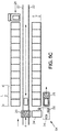
- FIG. 5A which is a schematic top view, it is expected to have a transfer / unload area on the left and to have a transfer / delivery area on the right. It is also proposed in this figure to have side by side shelves 2 each comprising three columns of housing. The length L of a shelf and its width l are adapted according to the size of the bins 12 to be stored in the housing 10.
- the Figure 5B represents an alternative embodiment of the Figure 5A . It is proposed here to have shelves 2 on both sides of the conveyor 4. The solution proposed here allows an optimization of the space as it will be clear to the skilled person.
- the Figure 5C still presents another variant embodiment.
- This variant is based on the embodiment of the Figure 5B but could also be adapted to the embodiment of the Figure 5A with shelves on one side of the conveyor 4.
- the picking carriage 28 arrives at the transfer zone for unloading it in a position such as the bins 12 that it transport are oriented at 90 ° to the position they must take on the conveyor 20 (and in the housing 10).
- a turning station 54 is then provided.
- the latter comprises, for example, a raceway 24 'similar to a raceway 24 of a shelf 2.
- This second raceway 24' is pivotally mounted so as to be able to pivot 90 ° while remaining in the same horizontal plane.
- this second raceway 24 ' is mounted on at least one motorized wheel 56 while being connected to a turning pivot 58.
- the turning station 54 has as many tracks 24 'superimposed that there can be bins 12 on a carriage 28.
- This turning station 54 is for example the following.
- a control carriage 28 is brought face to the turning station 54.
- An operator then controls the 90 ° rotation of the structure carrying the two superimposed raceways 24 'and located on levels adapted to the position of the bins 12 on the carriage 28.
- the operator pushes the two bins on the raceways 24'. They are then held by a barrier actuated by an electric jack (not shown). It then requests the return to 90 ° of the structure carrying the two raceways 24 '(and for example one or two bins 12).
- the raceways 24 ' are inclined relative to the horizontal so that the tanks 12 come into contact with the barrier by gravity.
- the bins 12 on the raceways 24 'are then aligned with the conveyor 20 of the carrier, ready to be unloaded.
- the actuator erases the barrier which held the tray to be unloaded on the raceway 24 'and releases the tray 12 which is received by the conveyor 20 to be stored in its housing 10 of destination.
- the turning angle could be different from 90 °. If the orientation of the tray in the housing 10 is important, a rotation of 180 ° is for example possible. A rotation of 270 ° can also be considered as well as all the intermediate angular values.
- a turning station can also be envisaged at the transfer zone used for the delivery of the bins 12 (with the delivery carriage 26.
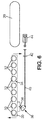
- the figure 6 illustrates a mechanism for moving a tray 12 from a housing 10 to the conveyor 20. There is recognized in this figure a raceway 24 and the conveyor 20.
- the raceway 24 is formed of a frame 30 in which are mounted rollers 32 arranged parallel to each other.
- the frame 30 is pivotally mounted about an axis 34 parallel to the rollers 32.
- a roller 36 cooperating with a cam 38 Under the frame 30, for example in a median position with respect to the length of the rollers 32, is a roller 36 cooperating with a cam 38.
- the roller 36 and the cam 38 are each mounted pivotally about an axis parallel to the 34.
- the roller 36 is mounted on the frame 30 while the cam 38 is mounted on the shelf 2, for example on a shelf 6 (below it).
- the cam 38 is controlled by means of a rod 40 which extends substantially parallel to the frame 30, below it.
- the cam 38 is disposed near the bottom of a housing 10 and the rod 40 extends towards the opening of the housing 10.
- the rod 40 is for example guided by a guide bearing 42 fixed under a shelf 6 (in a central position relative to an opening of a housing 10 if the cam 38 and the roller 36 are arranged in a median position relative to the raceway 24).
- rollers 32 there are four rollers 32 on one side of the axis 34 and five of the other.
- the presence of the roller 36 also creates an unbalance towards the bottom of the housing 10. If necessary, it is also possible to provide a return spring in the rest position of the frame 30, for example at the level of the housing. axis 34.
- This embodiment (that of figures 7 also) is simple because it allows to have only one cylinder to control all the tracks 24 of the housing 10.
- FIG. 7A and 7B An alternative embodiment of the tilt mechanism illustrated in the figure 6 is represented on the Figures 7A and 7B . It is recognized in these figures the raceway 24 with its rollers 32 and hinged about its axis 34 horizontal.
- the tilting mechanism illustrated here also includes a bead wire 40 'which interacts with the cylinder 44 (or other actuator) in the same manner as that illustrated in FIG. figure 6 . It further comprises a rocking assembly.
- the rocker assembly comprises two symmetrical flanges 60 connected by axes.
- Each flange 60 is for example made from a sheet cut to have an overall L shape.
- the two flanges 60 are arranged in a substantially vertical plane, perpendicular to the axis 34.
- the views 7A and 7B do not allow to see each time a single flange 60.
- Each flange 60 is pivotally mounted on a support 62, possibly common to the two flanges 60, fixed (for example welded) on the structure of the corresponding shelf 2.
- the fasteners of the flanges 60 on their support 62 define an articulation axis 64.
- Each flange 60 having an L shape, it has a first arm 66 and a second arm 68.
- the hinge pin 64 cuts the flanges 60 substantially halfway up the first arms 66.
- the ends of the first arms 66 are connected by an axis carrying at least one wheel 70 which is intended to come into contact with the raceway 24, the frame of the latter coming for example on the wheel (s) 70.
- the second arms 68 are connected by another axis which carries at least one counterweight 72.
- the L of the flanges 60 is oriented so that the first arm 66 is turned towards the raceway 24 (thus upwards since the rocker assembly is disposed under said raceway) and so that the second arm 68 is oriented opposite the conveyor 20, and therefore the rod 40 '.
- the rocker assembly is pivotable between two positions which are each stable. It is placed between the axis 34 and the conveyor 20 (or the conveyor 4). In the first rest position, the first arm 66 is slightly inclined relative to the vertical of the opposite side to the conveyor 20 (or to the conveyor 4): a straight line in a vertical plane passing through the axis hinge 64 and the axis bearing the (the) wheel (s) 70 is slightly inclined.
- a stop 74 for example in the form of a sheet fixed under the raceway, parallel to the rollers 32 is provided to receive the (the) wheel (s) 70 resting in the rest position of the raceway 24 This position is stable because, due to the inclination of the first arm 66, when the rocking assembly is pivoted to move the wheel (s) away from the abutment 74, it is necessary to slightly lift the raceway 24. This makes a hard point in the pivoting movement of the rocking assembly.
- the stop 74 comes to bear on a concave zone 76 formed at the junction between the first arm 66 and the second arm 68.
- the stop 74 is used for the stability of the two stable positions of the rocking assembly. It is clear that separate means could make it possible to obtain stability in the second position.
- a housing 10 When a housing 10 is empty and will receive a tray, its raceway 24 is in the so-called rest position, that is to say, inclined opposite the conveyor 4.
- the conveyor 20 arrives facing the housing 10, it is positioned to be at least at the height of the end of the tread 24 the highest, that is to say also closest to the conveyor 20.
- the latter can then transfer the tray 12 it carries to the housing 10 by rolling first on the conveyor alone, then on the conveyor and the raceway and finally on the raceway alone.
- the tray 12 Given the inclination of the raceway 24, the tray 12 is driven by gravity towards the end of the raceway 24 opposite the conveyor 20. It then comes into abutment at the end of the raceway.
- the stop may be integrated in the raceway 24, or to the shelf 2. It may also for example be a wall against which the shelf 2 would be.
- the conveyor 20 faces the housing 10 but in a position a little lower than that described above for the loading of the housing 10.
- the position of the conveyor 20 is such that the cylinder 44 can cooperate with the rod 40 or 40 '.
- the jack 44 When the jack 44 is actuated, it acts on the rod (40 or 40 ') which pivots the cam 38 ( figure 6 ) or the tilting assembly of the figure 7 (A and B).
- the raceway 24 then passes into its second position and by gravity, the tray 12 in the housing 10 rolls towards the conveyor 20 which then supports the tray 12.
- the cylinder 44 retracts and the raceway 24 returns to its first position.
- FIG. 8 illustrates a preferred embodiment of a picking preparation carriage 28.
- This carriage is for example designed to be operated by a central unit indicated by a command management software and an onboard automaton for functions.
- Subsidiaries assigned to the processing of several orders placed online to a merchant site via the internet or via any other means of communication.
- a merchant site has one (or more) store (s) for storing the products offered for sale, each of these stores comprising product storage gondolas or the like, separated by aisles.
- each gondola is formed of a supporting frame and several horizontal shelves, carried by the supporting frame. Products offered for sale are stored on horizontal shelves.
- the picking preparation carriage 28 comprises a rigid chassis, low ground clearance, mounted on five wheels namely two front wheels 46, two central wheels 47 and a rear wheel 48 free also.
- the front wheels 46 and the rear wheel are for example free while the two central wheels 47 are driving, each drive wheel having its own motor.
- the two wheels thus form the propulsion unit which is connected to the central unit via the onboard PLC and a drive.
- the propulsion unit is supplied with electrical energy by an on-board rechargeable electric power source formed of electric batteries.
- the controller allows, via the drive, different speed commands to one or the other element of the propulsion unit, thus allowing the direction of the truck to be changed.
- the frame of the carriage is for example formed of two parallel longitudinal members, and joined to each other by front and rear rails.
- This carriage also includes side flanks parallel to its direction and front and rear flanks transverse to its direction of advancement.
- On this chassis is a platform forming a cockpit 50 provided to receive a preparer. Thus the preparer is embedded on the cart.
- the carriage Adjacent to the cockpit 50, the carriage has two handles 52 to be held by the preparer standing on the platform when moving the carriage. These handles 52 allow the preparer to secure his balance. It is advantageously provided that the absence of "presence" of a hand on a single handle controls the stopping of the propulsion unit.
- the picking carriage 28 On the side of the platform opposite the side having the handles 52 for holding and safety, the picking carriage 28 is equipped with a magazine adapted to removably receive a plurality of trays 12. These are arranged in the store so superimposed and each of them is intended to receive the items of one of the commands to be processed by the preparer.
- the layout of a store equipped with several bins 12 allows the simultaneous processing of several orders.
- the cockpit 50 is open laterally so that the preparer can easily access the products stored in the gondolas.
- the preparer is standing in the cockpit.
- the magazine is located at the rear of the carriage 1.
- the magazine is formed of a supporting framework defining, in successive height levels, several housings respectively adapted to removably receive the bins 12. Each housing is open both forwards and backwards to allow the removal or placement of each tray 12 is from the rear of the truck or from the cockpit 50.
- each tray 12 is slidably mounted in its housing to be able to be pulled backwards or pushed forward, depending on the configuration chosen, by the preparer. view of the introduction of the different items ordered.
- each housing comprises a horizontal bottom provided to support the corresponding tray 12. This horizontal bottom is formed of a raceway 24 'formed by a frame 30' and a succession of horizontal rollers 32 'carried by the frame 30' and freely rotatably mounted in the latter, each along a geometric axis perpendicular to the direction of carriage advancement.
- the horizontal bottom is movably mounted in horizontal translation and for this purpose is slidably carried by horizontal slides fixed to the frame of the magazine and extending parallel to the direction of advance of the preparation trolley.
- the purpose of such a configuration is to make it possible to arrange the horizontal movable floor in a rear overhang with respect to the framework of the store in order to facilitate the operations of loading and unloading the containers 12 from the rear of the store.
- the movable bottom occupies a retracted position in the frame of the store.
- each slide has a front end stop to prevent the horizontal bottom of the housing from entering the cockpit 50.
- each slide has a rear stop capable of limiting the rearward movement of the bottom of the housing. each housing and consequently the importance of the rear overhang.
- Each housing on the picking carriage 28 is associated locking means adapted in the locking position to maintain the tray 12 on its raceway 24 ', the locking means being operable from the cockpit 50.
- This means of locking may be constituted by an axle longitudinally passing through the frame 30 'with a rotary handle end axis, operable from the cockpit 50 and a stop perpendicular to the axis of the opposite side to the rotary handle. In the working position, the stop is disposed on the path of the tray 12 to maintain the latter in the usual position of use. In the delivery position of the tray 12 to the conveyor 4, or any other storage location, the preparer unlocks the stop by rotating a quarter turn of the rotary handle, thus releasing the tray 12 which can then be pushed to the outside to the conveyor 20.
- the storage and transfer device proposed here makes it possible with simple means to optimize the management of orders prepared in a shop of a commercial site.
- this device can also find applications in an industrial site for the preparation of batches of parts or for the production of various lots - spare parts, assembly subassemblies, ....
- the system proposed here also has the advantage of being compact. It is also flexible. Indeed, it can adapt to many styles of management. Order preparations can be managed on one side and deliveries on the other.
- the system described with reference to the figures comprises a conveyor with a single conveyor. It can be envisaged to have at least two conveyors to increase the productivity of the system. With two conveyors, one could for example provide that the two conveyors are mounted on the same mast 18 or have two separate sets each formed of a mast and a conveyor.
Landscapes
- Engineering & Computer Science (AREA)
- Mechanical Engineering (AREA)
- Warehouses Or Storage Devices (AREA)
Applications Claiming Priority (1)
| Application Number | Priority Date | Filing Date | Title |
|---|---|---|---|
| FR1556226A FR3038308B1 (fr) | 2015-07-01 | 2015-07-01 | Dispositif de stockage et de transfert |
Publications (2)
| Publication Number | Publication Date |
|---|---|
| EP3112294A2 true EP3112294A2 (de) | 2017-01-04 |
| EP3112294A3 EP3112294A3 (de) | 2017-03-22 |
Family
ID=54199831
Family Applications (1)
| Application Number | Title | Priority Date | Filing Date |
|---|---|---|---|
| EP16177638.0A Withdrawn EP3112294A3 (de) | 2015-07-01 | 2016-07-01 | Lager- und transportvorrichtung |
Country Status (2)
| Country | Link |
|---|---|
| EP (1) | EP3112294A3 (de) |
| FR (1) | FR3038308B1 (de) |
Cited By (8)
| Publication number | Priority date | Publication date | Assignee | Title |
|---|---|---|---|---|
| CN109229462A (zh) * | 2018-09-05 | 2019-01-18 | 浙江工业大学 | 分轨式草莓存储装置 |
| CN109335431A (zh) * | 2018-09-12 | 2019-02-15 | 刘丽娜 | 一种基于无线网络的计算机远程控制的超市理货机器人 |
| CN110510321A (zh) * | 2019-09-23 | 2019-11-29 | 江苏弘东工业自动化有限公司 | 自动化料库 |
| CN110902295A (zh) * | 2019-12-30 | 2020-03-24 | 苏州优王电子科技有限公司 | 周转箱传输装置 |
| CN111603707A (zh) * | 2020-05-07 | 2020-09-01 | 蓝谷智慧(北京)能源科技有限公司 | 一种防火储能站 |
| DE102020130484A1 (de) | 2020-11-18 | 2022-05-19 | Harburg-Freudenberger Maschinenbau Gmbh | Transportsystem zum Transport von Materialeinheiten in der Materialverarbeitung und Verfahren zum Transport von Materialeinheiten |
| CN115279671A (zh) * | 2020-03-06 | 2022-11-01 | 卡迪斯制造(德国)有限公司 | 具有彼此倾斜定向的两个转移位置的储存系统 |
| CN116040183A (zh) * | 2023-01-10 | 2023-05-02 | 福州友宝电子科技有限公司 | 一种仓储管理用智能rfid感知柜 |
Families Citing this family (1)
| Publication number | Priority date | Publication date | Assignee | Title |
|---|---|---|---|---|
| CN113927726A (zh) * | 2021-11-23 | 2022-01-14 | 江苏金雷建材有限公司 | 一种框架式混凝土预制构件模具堆垛装置 |
Family Cites Families (10)
| Publication number | Priority date | Publication date | Assignee | Title |
|---|---|---|---|---|
| JPS58167308A (ja) * | 1982-03-26 | 1983-10-03 | Hitachi Ltd | ピツキング装置 |
| JPS58212501A (ja) * | 1982-05-31 | 1983-12-10 | Kao Corp | ピッキング装置 |
| JPS6331910A (ja) * | 1986-07-28 | 1988-02-10 | Nippon Mujinka Syst Kk | 多段式角氷倉庫の搬入搬出装置 |
| JPH01162407U (de) * | 1988-04-28 | 1989-11-13 | ||
| JPH0248316A (ja) * | 1988-08-08 | 1990-02-19 | Tomoegumi Giken:Kk | 円形長尺部材の収納棚 |
| DE19953812A1 (de) * | 1999-11-09 | 2001-05-23 | Psb Gmbh Materialflus & Logist | Verfahren und Vorrichtung zum Kommissionieren |
| FR2884237A1 (fr) * | 2005-08-01 | 2006-10-13 | Faurecia Bloc Avant | Installation de transport et de manutention d'equipements de vehicule automobile |
| JP2008266011A (ja) * | 2007-04-19 | 2008-11-06 | Katsuyuki Kojima | 微小昇降積載台を具えたドーリと立体収納棚 |
| AT508269A1 (de) * | 2009-05-28 | 2010-12-15 | Tgw Mechanics Gmbh | Kommissioniereinrichtung |
| WO2014092145A1 (ja) * | 2012-12-14 | 2014-06-19 | 中西金属工業株式会社 | 自動倉庫 |
-
2015
- 2015-07-01 FR FR1556226A patent/FR3038308B1/fr not_active Expired - Fee Related
-
2016
- 2016-07-01 EP EP16177638.0A patent/EP3112294A3/de not_active Withdrawn
Non-Patent Citations (1)
| Title |
|---|
| None |
Cited By (10)
| Publication number | Priority date | Publication date | Assignee | Title |
|---|---|---|---|---|
| CN109229462A (zh) * | 2018-09-05 | 2019-01-18 | 浙江工业大学 | 分轨式草莓存储装置 |
| CN109335431A (zh) * | 2018-09-12 | 2019-02-15 | 刘丽娜 | 一种基于无线网络的计算机远程控制的超市理货机器人 |
| CN110510321A (zh) * | 2019-09-23 | 2019-11-29 | 江苏弘东工业自动化有限公司 | 自动化料库 |
| CN110510321B (zh) * | 2019-09-23 | 2024-06-11 | 江苏弘东工业自动化有限公司 | 自动化料库 |
| CN110902295A (zh) * | 2019-12-30 | 2020-03-24 | 苏州优王电子科技有限公司 | 周转箱传输装置 |
| CN115279671A (zh) * | 2020-03-06 | 2022-11-01 | 卡迪斯制造(德国)有限公司 | 具有彼此倾斜定向的两个转移位置的储存系统 |
| CN111603707A (zh) * | 2020-05-07 | 2020-09-01 | 蓝谷智慧(北京)能源科技有限公司 | 一种防火储能站 |
| DE102020130484A1 (de) | 2020-11-18 | 2022-05-19 | Harburg-Freudenberger Maschinenbau Gmbh | Transportsystem zum Transport von Materialeinheiten in der Materialverarbeitung und Verfahren zum Transport von Materialeinheiten |
| DE102020130484B4 (de) | 2020-11-18 | 2022-12-01 | Harburg-Freudenberger Maschinenbau Gmbh | Transportsystem zum Transport von Materialeinheiten in der Materialverarbeitung und Verfahren zum Transport von Materialeinheiten |
| CN116040183A (zh) * | 2023-01-10 | 2023-05-02 | 福州友宝电子科技有限公司 | 一种仓储管理用智能rfid感知柜 |
Also Published As
| Publication number | Publication date |
|---|---|
| FR3038308A1 (fr) | 2017-01-06 |
| FR3038308B1 (fr) | 2020-05-22 |
| EP3112294A3 (de) | 2017-03-22 |
Similar Documents
| Publication | Publication Date | Title |
|---|---|---|
| EP3112294A2 (de) | Lager- und transportvorrichtung | |
| EP0169156B1 (de) | Selbstangetriebener Wagen mit Fördereinrichtung durch Roboter | |
| EP0764417B1 (de) | Anlage zum Kontrollieren und Erfassen von Anschaffungen in einer Selbstbedienung | |
| FR3042182A1 (fr) | Systeme de preparation de commandes | |
| EP4214140B1 (de) | Verfahren zum betrieb eines kommissionier- oder pufferspeichersystems | |
| EP2222418A1 (de) | Vorrichtung zum entladen von behältern mittels eines schwingelements | |
| CA2000478A1 (fr) | Distributeur automatique de produits alimentaires du type pains ou baguettes et procede de gestion et de distribution des produits | |
| FR2907368A1 (fr) | Machine de faconnage d'ebauches de caisses en carton. | |
| EP2796390B1 (de) | Automatisches transport- und lagersystem für produkte zur vorbereitung ihrer bestellungen und kontrollverfahren dieses systems | |
| FR3013022A1 (fr) | Chariot de transport ameliore | |
| WO2021176184A9 (fr) | Système et procédé de transfert de contenants dans un entrepôt de stockage | |
| FR3021614A1 (fr) | Chariot de transport d'unites de stockage et station de chargement-dechargement associee | |
| WO1986006051A1 (fr) | Chariot de transfert de plateaux, notamment pour lyophilisateur, et installation de chargement/dechargement correspondante | |
| FR2967145A1 (fr) | Systeme de stockage automatise comprenant au moins un elevateur dont au moins un mat porteur est forme par au moins un montant de la structure d'au moins une etagere | |
| FR3056971A1 (fr) | Deplacement de produits dans une ligne | |
| FR2864053A1 (fr) | Vehicule de transport d'objets en vrac et installation de transport | |
| EP4554877A1 (de) | System und verfahren zum kommissionieren von aufträgen | |
| FR2615778A2 (fr) | Appareil de transport et de manutention de charges comprenant un chariot sans conducteur a fourche de levage | |
| WO2024126306A1 (fr) | Dispositif de manutention et procédé de manutention | |
| EP3359472A1 (de) | Vorrichtung und verfahren zur herstellung eines lastaufnahmebehälters und anordnung mit diesem behälter sowie derartige vorrichtung | |
| FR3157367A1 (fr) | Procédé de déchargement et/ou de chargement, et installation convenant pour la mise en œuvre du procédé. | |
| WO2025219421A1 (fr) | Véhicule pour système automatisé de stockage et système de stockage et de récupération d'articles | |
| FR2682080A1 (fr) | Procede de manutention automatique de bouteilles de grande capacite, en particulier de gaz liquefie, et installation pour la mise en óoeuvre du procede. | |
| FR2920414A1 (fr) | Chariot pour la collecte de produits d'emballage destines a etre achemines vers une unite de traitement, de recyclage, ou de recuperation | |
| FR3040381A1 (fr) | Systeme pour le prelevement d'articles en stock |
Legal Events
| Date | Code | Title | Description |
|---|---|---|---|
| PUAI | Public reference made under article 153(3) epc to a published international application that has entered the european phase |
Free format text: ORIGINAL CODE: 0009012 |
|
| STAA | Information on the status of an ep patent application or granted ep patent |
Free format text: STATUS: THE APPLICATION HAS BEEN PUBLISHED |
|
| AK | Designated contracting states |
Kind code of ref document: A2 Designated state(s): AL AT BE BG CH CY CZ DE DK EE ES FI FR GB GR HR HU IE IS IT LI LT LU LV MC MK MT NL NO PL PT RO RS SE SI SK SM TR |
|
| AX | Request for extension of the european patent |
Extension state: BA ME |
|
| PUAL | Search report despatched |
Free format text: ORIGINAL CODE: 0009013 |
|
| AK | Designated contracting states |
Kind code of ref document: A3 Designated state(s): AL AT BE BG CH CY CZ DE DK EE ES FI FR GB GR HR HU IE IS IT LI LT LU LV MC MK MT NL NO PL PT RO RS SE SI SK SM TR |
|
| AX | Request for extension of the european patent |
Extension state: BA ME |
|
| RIC1 | Information provided on ipc code assigned before grant |
Ipc: B65G 1/08 20060101ALI20170215BHEP Ipc: B65G 1/04 20060101AFI20170215BHEP Ipc: B65G 13/12 20060101ALN20170215BHEP |
|
| STAA | Information on the status of an ep patent application or granted ep patent |
Free format text: STATUS: THE APPLICATION IS DEEMED TO BE WITHDRAWN |
|
| 18D | Application deemed to be withdrawn |
Effective date: 20170923 |