EP3113286A1 - Quasioptischer strahlformer mit linse, und flachantenne, die einen solchen strahlformer umfasst - Google Patents
Quasioptischer strahlformer mit linse, und flachantenne, die einen solchen strahlformer umfasst Download PDFInfo
- Publication number
- EP3113286A1 EP3113286A1 EP16176732.2A EP16176732A EP3113286A1 EP 3113286 A1 EP3113286 A1 EP 3113286A1 EP 16176732 A EP16176732 A EP 16176732A EP 3113286 A1 EP3113286 A1 EP 3113286A1
- Authority
- EP
- European Patent Office
- Prior art keywords
- transmission line
- quasi
- lens
- protrusion
- beamformer
- Prior art date
- Legal status (The legal status is an assumption and is not a legal conclusion. Google has not performed a legal analysis and makes no representation as to the accuracy of the status listed.)
- Granted
Links
Images


Classifications
-
- H—ELECTRICITY
- H01—ELECTRIC ELEMENTS
- H01Q—ANTENNAS, i.e. RADIO AERIALS
- H01Q15/00—Devices for reflection, refraction, diffraction or polarisation of waves radiated from an antenna, e.g. quasi-optical devices
- H01Q15/02—Refracting or diffracting devices, e.g. lens, prism
- H01Q15/04—Refracting or diffracting devices, e.g. lens, prism comprising wave-guiding channel or channels bounded by effective conductive surfaces substantially perpendicular to the electric vector of the wave, e.g. parallel-plate waveguide lens
-
- H—ELECTRICITY
- H01—ELECTRIC ELEMENTS
- H01Q—ANTENNAS, i.e. RADIO AERIALS
- H01Q25/00—Antennas or antenna systems providing at least two radiating patterns
- H01Q25/007—Antennas or antenna systems providing at least two radiating patterns using two or more primary active elements in the focal region of a focusing device
- H01Q25/008—Antennas or antenna systems providing at least two radiating patterns using two or more primary active elements in the focal region of a focusing device lens fed multibeam arrays
-
- H—ELECTRICITY
- H01—ELECTRIC ELEMENTS
- H01Q—ANTENNAS, i.e. RADIO AERIALS
- H01Q15/00—Devices for reflection, refraction, diffraction or polarisation of waves radiated from an antenna, e.g. quasi-optical devices
- H01Q15/02—Refracting or diffracting devices, e.g. lens, prism
-
- H—ELECTRICITY
- H01—ELECTRIC ELEMENTS
- H01Q—ANTENNAS, i.e. RADIO AERIALS
- H01Q15/00—Devices for reflection, refraction, diffraction or polarisation of waves radiated from an antenna, e.g. quasi-optical devices
- H01Q15/02—Refracting or diffracting devices, e.g. lens, prism
- H01Q15/10—Refracting or diffracting devices, e.g. lens, prism comprising three-dimensional [3D] array of impedance discontinuities, e.g. holes in conductive surfaces or conductive discs forming artificial dielectric
-
- H—ELECTRICITY
- H01—ELECTRIC ELEMENTS
- H01Q—ANTENNAS, i.e. RADIO AERIALS
- H01Q19/00—Combinations of primary active antenna elements and units with secondary devices, e.g. with quasi-optical devices, for giving the antenna a desired directional characteristic
- H01Q19/06—Combinations of primary active antenna elements and units with secondary devices, e.g. with quasi-optical devices, for giving the antenna a desired directional characteristic using refracting or diffracting devices, e.g. lens
- H01Q19/08—Combinations of primary active antenna elements and units with secondary devices, e.g. with quasi-optical devices, for giving the antenna a desired directional characteristic using refracting or diffracting devices, e.g. lens for modifying the radiation pattern of a radiating horn in which it is located
-
- H—ELECTRICITY
- H01—ELECTRIC ELEMENTS
- H01Q—ANTENNAS, i.e. RADIO AERIALS
- H01Q21/00—Antenna arrays or systems
- H01Q21/0006—Particular feeding systems
- H01Q21/0031—Parallel-plate fed arrays; Lens-fed arrays
-
- H—ELECTRICITY
- H01—ELECTRIC ELEMENTS
- H01Q—ANTENNAS, i.e. RADIO AERIALS
- H01Q3/00—Arrangements for changing or varying the orientation or the shape of the directional pattern of the waves radiated from an antenna or antenna system
- H01Q3/26—Arrangements for changing or varying the orientation or the shape of the directional pattern of the waves radiated from an antenna or antenna system varying the relative phase or relative amplitude of energisation between two or more active radiating elements; varying the distribution of energy across a radiating aperture
- H01Q3/2658—Phased-array fed focussing structure
-
- H—ELECTRICITY
- H01—ELECTRIC ELEMENTS
- H01Q—ANTENNAS, i.e. RADIO AERIALS
- H01Q3/00—Arrangements for changing or varying the orientation or the shape of the directional pattern of the waves radiated from an antenna or antenna system
- H01Q3/26—Arrangements for changing or varying the orientation or the shape of the directional pattern of the waves radiated from an antenna or antenna system varying the relative phase or relative amplitude of energisation between two or more active radiating elements; varying the distribution of energy across a radiating aperture
- H01Q3/2664—Arrangements for changing or varying the orientation or the shape of the directional pattern of the waves radiated from an antenna or antenna system varying the relative phase or relative amplitude of energisation between two or more active radiating elements; varying the distribution of energy across a radiating aperture electrically moving the phase centre of a radiating element in the focal plane of a focussing device
Definitions
- the present invention relates to a quasi-optical lens beamformer and a planar antenna having such a beamformer. It applies to any thin multibeam antenna and more particularly to the field of space applications such as satellite telecommunications, for antennas intended to be mounted on board satellites, or for antennas intended to be used on the ground on satellites. fixed or mobile terminals.
- the mode of operation of the beam formers is assumed in transmission, but a similar description could be formulated in reception, the beam trainers considered being passive elements therefore reciprocal.
- the beamformers are used in multibeam antennas to develop output beams from input radio frequency signals.
- planar quasi-optical beamformers using electromagnetic propagation of radiofrequency waves between two parallel metal plates (in English: parallel plates), according to a propagation mode in general TEM (in English: Transverse Electric Magnetic) for which the electric and magnetic fields are orthogonal to the propagation direction of the radiofrequency waves.
- the TEM mode propagates in the parallel plate guide at the same speed as in vacuum, which renders said guide non-dispersive for this TEM mode.
- the focusing and collimation of the beams can be performed by a constrained lens, as described for example in the documents US 3170158 and US 5936588 which illustrate the case of a Rotman lens, or alternatively by a reflector as described for example in the documents FR 2944153 and FR 2 986377 for Pillbox beam formers, the constrained lens, or respectively the reflector, being inserted in the propagation path of the radiofrequency waves, between the two parallel metal plates.
- the constrained lens, or the reflector serves essentially as phase corrector and makes it possible, by transmission in the case of a lens, or after reflection in the case of a reflector, to convert cylindrical wave fronts into plane wave fronts.
- a Pillbox beamformer may, at output, be connected to a linear array of several individual radiating elements aligned side by side.
- the linear output opening located between the two parallel plates, it is also possible to connect the linear output opening, located between the two parallel plates, to a single linear output horn which makes the transition between the parallel plates and the free space where beams are radiated.
- the radiating aperture at the output of the Pillbox beamformer is linear and extends continuously over the entire transverse width of the parallel plates.
- radio-frequency waves are constrained, i.e., guided, along a propagation path that does not correspond to a natural optical path, free space, as defined by the laws of Snell-Descartes.
- These beamformers can be synthesized to have three or four different foci, resulting in fewer aberrations and better beams.
- these beam formers need to take radiofrequency waves along the internal contour. of the lens by a network of different delay transmission lines.
- the transmission lines used are coaxial lines, but this necessitates a transition between the coaxial lines and the linear radiating opening, and the structure of the beamformer is then not completely integrated.
- the transmission lines used are coaxial lines, but this necessitates a transition between the coaxial lines and the linear radiating opening, and the structure of the beamformer is then not completely integrated.
- the object of the invention is to provide a novel quasi-optical lens-beamformer for converting cylindrical wavefronts into plane wavefronts by applying differential delays between the center and the lateral edges of the beam.
- the lens not having the disadvantages of known constraint lens beam formers, to overcome the spatial sampling of radio frequency waves, and allowing the use of a single output linear horn.
- the quasi-optical lens beamformer comprises a radio frequency transmission line fed at a first end, by at least one input power source, the transmission line comprising two stacked metal plates. , spaced from one another and extending in two longitudinal X and transverse Y directions.
- the transmission line further comprises at least one protrusion extending in the directions X, Y, and in a direction Z orthogonal to the XY plane, the projection having a metal insert extending in the direction X, in the transverse direction Y between two lateral edges of the lens, and extending in height in the direction Z.
- the metal insert comprises a base secured to one of the two metal plates, at least one free end and has, in longitudinal section, a contour of variable length between the two lateral edges of the transmission line.
- the transmission line is contiguous to the metal insert and forms, in the Z direction, a convolution around the metal insert.
- the free end of the insert can be folded parallel to the XY plane.
- the free end of the insert can be doubly folded T-shaped, parallel to the XY plane.
- the protrusion and the metal insert may have a profile of curvilinear shape along the X and Y directions.
- the protrusion may have an input profile and an output profile of different shapes.
- the outgrowth may comprise adaptation stubs.
- the metal plates of the transmission line may have an internal face having transitions in steps.
- the length of the contour of the metal insert can be progressively decreasing from the center towards the two lateral edges of the transmission line.
- the length of the contour, in longitudinal section, of the metal insert can be progressively increasing from the center towards the two lateral edges of the transmission line.
- the metal insert may comprise a symmetrical profile with respect to the median longitudinal axis of the transmission line.
- the lens may comprise several input power sources distributed around an input edge, according to a focal curve.
- the beamformer may comprise a plurality of excrescences capable of producing progressive delays, the excrescences being successively distributed along the longitudinal axis X of the transmission line, at different distances from the input supply sources, each outgrowth comprising a metal insert whose length of the contour, in longitudinal section, varies between the two lateral edges of the transmission line.
- the length of the contour of the metal inserts, in the different successive excrescences may vary progressively from one protrusion to another adjacent protuberance, along the longitudinal direction X of the transmission line.
- the transmission line can be folded on itself in the X direction, according to a fold of straight shape.
- the beamformer may further comprise at least one first reflector wall extending transversely in the transmission line, and orthogonal to the metal plates in the Z direction, the first reflector wall being able to fold the transmission line, on itself, according to the X direction, according to a curvilinear fold.
- the quasi-optical lens-beamformer may comprise two layers stacked and closed at one end by the first reflector wall and two opposite protuberances arranged around a metal insert extending in the two stacked layers, the first reflective wall. being integrated with the two opposite growths.
- the quasi-optical lens-beamformer may further comprise a third layer stacked on the second layer and a second reflective wall extending in the second and third layers.
- the quasi-optical lens-beamformer may further include at least one third protrusion arranged in the second layer downstream of the first reflector wall.
- the invention also relates to a planar antenna comprising at least one such beamformer and further comprising a linear radiating horn connected at the output of the beamformer.
- the invention relates to a planar antenna comprising such a beamformer, the transmission line being folded on itself and having a linear output opening connected to an array of several radiating horns.
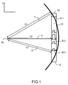
- the lens bundle trainer shown in the diagram of FIG. figure 1 and on the perspective view of the figure 2a comprises a transmission line 20 with two metal plates and a lens with progressive and continuous delays between the center 14 of the lens and the two lateral edges 15, 16.
- the transmission line 20 consists of two stacked metal plates, respectively upper and lower. lower, spaced from each other by a cavity, and extending in two longitudinal directions X and transverse Y.
- the transmission line 20 is fed at a first end, by at least one input power source 10 and is provided with a protrusion 13, located on the path of radio waves.
- the input and output contours of the protrusion which respectively correspond to the inner and outer contours of the lens, may have profiles of identical shapes and parallel to each other or may have different profiles.
- the protrusion 13 extends in thickness in the X direction, transversely in the width of the transmission line in the Y direction, and in height in a Z direction orthogonal to the XY plane of the metal plates, the length dL1, dL2, dL3 of the transmission line in the protrusion being variable from the center 14 to the two lateral edges 15, 16 of the lens, so as to apply a different delay to the radiofrequency waves propagating in the lens along paths 1, 2, 3 having different angular directions and respective lengths L1, L2, L3.
- the delay achieved by the protrusion is proportional to the length of the transmission line, in the protrusion, on the path considered.
- the delay applied to the radio frequency waves propagating along the median longitudinal axis 3 of the lens may be greater than the delays applied to all other paths while the delay applied to radiofrequency waves propagating towards the edges of the lens, which correspond to the longest paths, may be zero.
- the law of delays is different.
- the law of delays is more complex because it also depends on the respective shapes of said internal and external contours.
- the protrusion 13 comprises a metal insert 21 housed transversely in the cavity, between the two metal plates, the insert 21, of any shape, having a base 21b secured to one of the two metal plates, lower or upper, by for example, the lower metal plate, and at least one free end 21a.
- the metal insert 21 extends in width, in the transverse direction Y, between two lateral edges of the lens 15, 16, extends in thickness in the direction X, and extends in height, at least in part along the Z direction.
- the insert 21 has an outer contour of progressively variable length between the two lateral edges of the transmission line.
- the variation of the length of the contour of the insert 21 can be obtained by varying the height of the insert in the Z direction, or by varying the thickness of the insert in the X direction, or by combination of a variation in height in the direction Z and a variation in thickness in the direction X as illustrated for example on the Figures 3a, 3b, 3c .
- the figure 3a is an exploded diagram in perspective of an example of protrusion in which the insert has a variable height in the direction Z and a variable thickness in the direction X.
- the figure 3b shows two diagrams, in longitudinal section, respectively in the center of the lens and on the lateral edges of the lens, the outgrowth of the figure 3a .
- the insert has an I-shaped wall on the median longitudinal axis, in the center of the lens, and has an increased thickness and a reduced height on the lateral edges of the lens.
- the figure 3c is a perspective diagram of the beam trainer corresponding to the Figures 3a and 3b .
- the two input profiles 18 and 19 of the output protrusion 13, which respectively correspond to the internal contours and outer of the lens, are not parallel to each other.
- the transmission line 20 is contiguous to the metal insert 21 and thus forms, in the Z direction, a convolution 22 around the metal insert 21, as represented for example on the figure 4a for an insert having an I-shaped longitudinal section.
- the transmission line travels along the contour of the insert and thus changes orientation several times but does not include any transmission discontinuity.
- the transmission line continuously follows the shape of the insert 21, runs along a first front surface, from the base 21b to the free end 21a of the insert, and then runs along a second rear surface, from the end free 21 at the base 21 a.
- the propagation of the electromagnetic waves is always carried out between two metal plates and according to the propagation mode TEM, the insert 21, placed in the middle of the protrusion, ensuring the role of the metal plate, lower or upper , to which its base is solidarized.
- the direction of the electric field E in the transmission line rotates in the protrusion according to the orientation of the metal plates and remains, in all points of the transmission line, perpendicular to the metal plates, or almost perpendicular to the parallel plates when the metal plates are not exactly parallel.
- the insert 21 placed in the path of the electromagnetic waves TEM constitutes an obstacle to circumvent which causes a propagation delay all the more important that the insert has a longer contour.
- the law of variation of the length of the contour of the insert, in a transverse direction of the lens, depends on the desired delay law for the formation of the beams.
- the length of the contour of the metal insert may progressively vary from the center of the lens, located on the median longitudinal axis, to the lateral edges of the lens, so as to compensate for the difference in travel time between the different paths. and obtaining propagation paths of identical lengths across the entire width of the aperture radiating output of the lens.
- the lens is convergent when the variation of the length of the contour of the insert is progressively decreasing from the center towards the two lateral edges of the transmission line.
- the length of the contour of the insert is important in the center of the lens and may be zero on the lateral edges of the lens.
- the lens is divergent when the variation of the length of the contour of the insert is progressively increasing from the center towards the two lateral edges of the transmission line.
- a convergent lens is required.
- the combination of a converging lens and a diverging lens can minimize phase aberrations over a wider angular sector, and thus form more beams.
- the length of the contour of the insert may vary symmetrically on either side of the median longitudinal axis of the lens.
- the insert 21 can have different shapes.
- the insert when there is no thickness constraint for the beamformer, the insert can extend without limitation in the Z direction and have an I-shaped section across the entire width of the lens, as represented on the figure 4a .
- the insert when it is necessary to reduce the dimension of the growths, in the direction Z, to maintain a small thickness of the lens, for the large delays requiring insert heights greater than the desired thickness, to reduce the height of the insert without changing the length of its contour, it is possible to fold a free end 21a, opposite the base 21b, of the insert parallel to the XY plane, the folding can be single or double as shown in the embodiments of the Figures 4b and 4c , in which the insert 21 may have an L-shaped section when there is a simple folding, or a T-shaped section when there is a double folding.
- the metal insert 21 and the inner face 23 of the wall 22 of the protrusion 20 comprise transitions 24 at right angles corresponding, for the transmission line 20, to changes in direction of propagation of the direction Z towards the direction X or vice versa from the X direction towards the Z direction.
- the folding may not be necessary locally, on certain parts of the insert, for example on the lateral edges of the lens, when the local delays to be achieved are low. .
- the length of the contour of the folded insert 21 may be greater on the median longitudinal axis 3, at the center 14 of the lens, than on the other paths as shown in the view from above of the figure 4d then can gradually and symmetrically decrease to the two lateral edges 15, 16 of the lens where the folding is no longer necessary.
- the protrusion it is also possible to vary gradually the thickness of the insert, in the X direction, between the center and the lateral edges of the lens as on the Figures 4a, 4b , 4c .
- the input and output profiles of the protrusion which correspond to the inner and outer contours of the lens, are of different shapes. This makes it possible to obtain an additional degree of freedom and thus to obtain fewer aberrations and beams of better quality.
- the separation distance between the parallel plates must be reduced at the level of the excrescences, to be typically less than a quarter of the guided wavelength corresponding to the highest frequency.
- the separation distance must instead be maximum. It is thus possible to vary gradually the separation distance from the input supply sources 10 to the protuberances 13.
- adaptation stubs 25 to the protrusion 13, the adaptation stubs being consisting of portions of waveguides arranged symmetrically in the outer metal wall 22 of the protrusion 20, on either side of the metal insert 21.
- the stubs have a transversely variable profile, depending on the profile of the 13.
- the adaptation of the transmission line at the level of the protrusion can also be improved by replacing the edges of the angles at 90 °, located at the base of the insert and at the upper end of the outgrowth and corresponding to changes of direction of the transmission line, by bevel transitions or by stair step transitions as shown for example on Figures 5a, 5b , 5c .
- the protrusion 13 and the insert 21, placed on an exit edge of the lens may have a planar shape profile in the X and Y directions, as shown in FIGS. figures 1 and 2 or have a profile of curvilinear shape in the X and Y directions, for example parabolic as shown on the Figures 6a and 6b .
- the transmission line can have a linear input profile as on the figure 1 or a curvilinear entry profile.
- the transmission line comprises a plurality of input supply sources 10 distributed periodically around an input edge 31 of the lens in a focal curve, for example a focal arc, centered on a median longitudinal axis 3 of the lens .
- Curvilinear profiles at the entrance and exit of the lens make it possible to obtain several different focal points and to form beams over a wider angular sector.
- the electromagnetic wave at the output of the beamformer is not spatially quantized, and unlike a Pillbox formatter, the folding of the transmission line is not essential.
- the lens beam former according to the invention applies to the incident wave a continuous and gradually modulated transverse delay. Thanks to this continuity of spatial transmission, to obtain a plane antenna, it is possible, at the output of the lens, to connect the beamformer to a horn linear 35 extending transversely over the entire width of the waveguide, as shown in FIGS. Figures 6a and 6b or a network of linear openings extending transversely over the entire width of the waveguide as shown in FIGS. Figures 9 and 10 .
- the lens bundle trainer may comprise a single protrusion provided with a metal insert capable of producing progressive delays or a plurality of excrescences distributed along the longitudinal axis X of the transmission line, at different distances from the input power sources 10 as shown for example on the figures 7 and 8a .
- Each protrusion 13a, 13b, 13c, 13i, 13n extends in height in the direction Z orthogonal to the XY plane of the metal plates and comprises a metal insert whose length of the contour, in longitudinal section, varies progressively from the center of the lens, located on the median longitudinal axis, to the lateral edges of the lens.
- the multiplicity of excrescences makes it possible to distribute, between the different excrescences, the delays to be achieved for each propagation path 1, 2, 3, each protrusion realizing a fraction of the different respective delays. This makes it possible to reduce the amplitude of the delays produced by each outgrowth, to reduce the length dL1, dL2, dL3 of the transmission line, in each outgrowth, along the Z direction, and to reduce the height of the beamformer in the Z direction. .
- the fraction of the delays produced by each outgrowth may be identical for all the outgrowths or may vary according to the respective distance between each outgrowth and the input supply sources so as to obtain a gradient of delays in the longitudinal direction X of the transmission line.
- splitting the delays on seven successive growths distributed longitudinally it is possible to realize a gradient of delays in the longitudinal direction X.
- the height of the insert in the direction Z, in the different successive protuberances gradually varies along the longitudinal axis X of the transmission line.
- the length d.sub.L of the transmission line, around the insert, in each protrusion 13 increases between the first four protrusions closest to the input supply sources, then decreases over the last three excrescences. close to the linear output horn. Consequently, since the delay produced by each outgrowth is proportional to the length dL of the transmission line in the outgrowth, the fraction of the delays produced by each outgrowth varies in the same direction and increases between the first four outgrowths closest to the sources. 10 input power, then decreases on the last three outgrowths closest to the output linear horn.
- the lens thus produced makes it possible, thanks to each protrusion, to obtain a delay that varies progressively and continuously over the entire transverse width of the lens and, thanks to the fractionation of the delays on several successive excrescences, makes it possible to obtain a gradient of delays in the longitudinal direction.
- the lens behaves like a graded index lens.
- the value of the index in each outgrowth in the longitudinal direction is equal to (L + dL) / L, where L is the length of the transmission line in the longitudinal direction X, and dL is the length of the line transmission around the insert 21, in the corresponding protrusion 13.
- the beamformer By controlling the index gradient, or the delay gradient, it is thus possible to reduce the aberrations, for the depointed beams, over a wide angular sector. It also increases the number of degrees of freedom and focus points.
- the delay gradient transversely but also longitudinally, the beamformer can form beams without aberrations using transmission lines having a reduced length between the input power sources and the output radiating aperture.
- a single linear radiating horn is connected at the output of the transverse outgrowth of the continuous delay lens.
- the continuous delay lens may also be used to power a network of several linear radiating horns, such as the antenna shown in the diagram of the figure 9 .
- the parallel plate transmission line is folded back on itself, and has a linear output opening connected to the network of radiating horns 40 via power dividers 41. in this case, the folding of the transmission line is carried out in a straight line 42.
- the folding can be total 180 ° or partial and form an angle between 0 and 180 °.
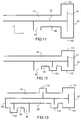
- the transmission line with a fold of curvilinear shape, for example parabolic, by inserting, in the transmission line, a reflective wall 43, for example metallic, extending according to Z direction, as shown for example in the diagrams of figures 10 , 11, 12 .
- the beam former consists of two layers 44, 45, stacked and closed at one end by the reflector wall 43 which extends transversely in the two layers of the beamformer, across the width and over all the height of the transmission line.
- the reflective wall can be of any shape, for example flat or parabolic.
- the beamformer includes at least one progressive delay lens input fed by one or more power sources 10 according to the invention, and has a linear output aperture 48.
- the progressive delay lens may be placed upstream or downstream of the reflector wall, or may be combined with the reflector wall to form an integrated assembly.
- the metal insert may be of any shape and may extend in height in the Z direction and / or in thickness in the X direction.
- the outlet linear opening 48 may be connected to a horn linear radiator 35 or to a network of several linear horns 40.
- the protrusion (s) 13, 13a, 13b, 13c developing the progressive and continuous delays of the lenses with delays can be arranged indifferently in the first or second layer, or in both layers of the beamformer.
- a single transverse protrusion 13 is arranged in the first layer 44 of the beam former, upstream of the reflecting wall 43.
- two opposing protuberances 131, 132 are arranged around a metal insert 21 extending in the two layers 44, 45 of the beam former and the reflecting wall 43 is integrated with the two opposite protuberances 131, 132.
- the metal insert extends in the Z direction, parallel to the reflector wall 43, but of course, alternatively, it could extend in thickness in the direction X.
- the shapes of the metal insert in the two layers are symmetrical, but it is not mandatory.
- the shapes of the metal insert in each protrusion and in each layer of the beamformer may be different from each other.
- the beam former comprises two transverse protrusions 131, 132 combined with the reflector wall 43 and arranged around a metal insert 21 extending in the two layers of the beamformer and further comprises at least a third transverse protrusion 133 arranged in downstream of the reflector 43, in the second layer of the beam former, between the reflecting wall 43 and the linear opening 48 of output.
- the radiofrequency waves emitted in the first layer at the input of the transmission line are delayed in the different protuberances of the continuous delay lenses, and reflected by the reflecting wall, towards the second layer before being radiated by the linear output horn. or through the network of linear output horns.
- the combination of a continuous-delay lens bundle combiner with a reflective wall has the advantage of increasing the number of degrees of freedom, the number of focusing points and improving the performance of the lens.
- the number of reflective walls may of course be greater than one, the growths may be located upstream or downstream of or reflective walls, and the reflective walls may or may not be incorporated into growths.
- the beamformer has a plurality of protuberances 131, 132, 133, 134, 135 and two reflector walls 43, 50.
- the first reflector wall 43 is integrated in the two opposite protuberances 131, 132, the third protrusion 133 is arranged downstream of the first reflector wall 43, between the first reflector wall 43 and the second reflector wall 50, the fourth protrusion 134 is arranged upstream of the first reflector wall 43, and finally the fifth protrusion 135 is arranged between the second reflector wall 50 and a linear output opening 48.
- the beamformer then comprises three stacked layers 44, 45, 46.
- the first reflector wall 43 extends into the first and second layers while the second reflector wall 50 extends into the second and third layers.
- the transmission line is then folded twice on itself, through the first reflective wall 43, then through the second reflector wall 50.
- the separation between the parallel plates must be reduced at the level of the growths, to be typically less than a quarter of the wavelength corresponding to the highest frequency among all the guided radio frequency waves, so that only the TEM mode can propagate.
- the separation distance must instead be maximum. It is thus possible to vary gradually the separation distance from the input supply sources 10 to the protuberances 13.
- the precisely described beamformer allows one beamline to be formed in a single XY plane since all power sources are located in the XY plane.
- planar beamformer according to the invention, with different planar beam formers, suitable for forming beams in a plane orthogonal to the XY plane, such as for example a Butler matrix.
- the shape of the protuberance and the shape of the insert may be different from the forms explicitly described.
- the dimensions of the insert may vary in height in the direction Z, or in thickness in the direction X, or vary in both height and thickness.
- the insert may comprise different types of folding and / or a number of folds greater than two, or a combination of several types of folds.
- the number of protrusions may be greater than one, the shape of the reflector may be arbitrary and the number of reflectors used may be greater than one.
- the protuberances can be placed upstream or downstream of a reflective wall.
- the beamformer may also include a reflector wall integrated with two protuberances. When the beamformer has two reflective walls, one or more protuberances can be arranged between the two reflective walls.
Landscapes
- Aerials With Secondary Devices (AREA)
Applications Claiming Priority (1)
| Application Number | Priority Date | Filing Date | Title |
|---|---|---|---|
| FR1501415A FR3038457B1 (fr) | 2015-07-03 | 2015-07-03 | Formateur de faisceaux quasi-optique a lentille et antenne plane comportant un tel formateur de faisceaux |
Publications (2)
| Publication Number | Publication Date |
|---|---|
| EP3113286A1 true EP3113286A1 (de) | 2017-01-04 |
| EP3113286B1 EP3113286B1 (de) | 2018-03-14 |
Family
ID=54545188
Family Applications (1)
| Application Number | Title | Priority Date | Filing Date |
|---|---|---|---|
| EP16176732.2A Active EP3113286B1 (de) | 2015-07-03 | 2016-06-28 | Quasioptischer strahlformer mit linse, und flachantenne, die einen solchen strahlformer umfasst |
Country Status (6)
| Country | Link |
|---|---|
| US (1) | US10135150B2 (de) |
| EP (1) | EP3113286B1 (de) |
| CA (1) | CA2934754C (de) |
| DK (1) | DK3113286T3 (de) |
| ES (1) | ES2669523T3 (de) |
| FR (1) | FR3038457B1 (de) |
Cited By (2)
| Publication number | Priority date | Publication date | Assignee | Title |
|---|---|---|---|---|
| CN109638408A (zh) * | 2018-12-05 | 2019-04-16 | 上海无线电设备研究所 | 一种应用于准动态缩比测试的v波段天线 |
| US10553957B2 (en) | 2017-07-27 | 2020-02-04 | Thales | Antenna integrating delay lenses in the interior of a distributor based on parallel-plate waveguide dividers |
Families Citing this family (5)
| Publication number | Priority date | Publication date | Assignee | Title |
|---|---|---|---|---|
| FR3076088B1 (fr) * | 2017-12-26 | 2020-01-10 | Thales | Formateur de faisceaux quasi-optique, antenne elementaire, systeme antennaire, plateforme et procede de telecommunications associes |
| CN108767475B (zh) * | 2018-04-28 | 2021-09-28 | 安徽四创电子股份有限公司 | 一种基于台阶变换的天线方向图赋形结构 |
| FR3095303B1 (fr) | 2019-04-18 | 2021-04-09 | Thales Sa | Ecran polariseur a cellule(s) polarisante(s) radiofrequence(s) large bande |
| US20250293439A1 (en) * | 2022-05-03 | 2025-09-18 | University Of Notre Dame Du Lac | Integration-Friendly Low-Profile Planar Grin Lens Antennas for Millimeter Wave Handheld Devices |
| FR3144427A1 (fr) * | 2022-12-22 | 2024-06-28 | Thales | Dispositif d'adaptation d'impédance à grand angle pour antenne réseau à éléments rayonnants et procédé de conception d'un tel dispositif |
Citations (6)
| Publication number | Priority date | Publication date | Assignee | Title |
|---|---|---|---|---|
| US3170158A (en) | 1963-05-08 | 1965-02-16 | Rotman Walter | Multiple beam radar antenna system |
| US5926134A (en) * | 1995-09-19 | 1999-07-20 | Dassault Electronique | Electronic scanning antenna |
| US5936588A (en) | 1998-06-05 | 1999-08-10 | Rao; Sudhakar K. | Reconfigurable multiple beam satellite phased array antenna |
| US6160520A (en) * | 1998-01-08 | 2000-12-12 | E★Star, Inc. | Distributed bifocal abbe-sine for wide-angle multi-beam and scanning antenna system |
| FR2944153A1 (fr) | 2009-04-02 | 2010-10-08 | Univ Rennes | Antenne multicouche a plans paralleles, de type pillbox, et systeme d'antenne correspondant |
| FR2986377A1 (fr) | 2012-01-27 | 2013-08-02 | Thales Sa | Formateur multi-faisceaux a deux dimensions, antenne comportant un tel formateur multi-faisceaux et systeme de telecommunication par satellite comportant une telle antenne |
Family Cites Families (2)
| Publication number | Priority date | Publication date | Assignee | Title |
|---|---|---|---|---|
| NL90090C (de) * | 1950-06-23 | |||
| WO2015172948A2 (en) * | 2014-05-14 | 2015-11-19 | Gapwaves Ab | Waveguides and transmission lines in gaps between parallel conducting surfaces |
-
2015
- 2015-07-03 FR FR1501415A patent/FR3038457B1/fr active Active
-
2016
- 2016-06-28 US US15/194,993 patent/US10135150B2/en active Active
- 2016-06-28 ES ES16176732.2T patent/ES2669523T3/es active Active
- 2016-06-28 DK DK16176732.2T patent/DK3113286T3/en active
- 2016-06-28 EP EP16176732.2A patent/EP3113286B1/de active Active
- 2016-06-30 CA CA2934754A patent/CA2934754C/en active Active
Patent Citations (6)
| Publication number | Priority date | Publication date | Assignee | Title |
|---|---|---|---|---|
| US3170158A (en) | 1963-05-08 | 1965-02-16 | Rotman Walter | Multiple beam radar antenna system |
| US5926134A (en) * | 1995-09-19 | 1999-07-20 | Dassault Electronique | Electronic scanning antenna |
| US6160520A (en) * | 1998-01-08 | 2000-12-12 | E★Star, Inc. | Distributed bifocal abbe-sine for wide-angle multi-beam and scanning antenna system |
| US5936588A (en) | 1998-06-05 | 1999-08-10 | Rao; Sudhakar K. | Reconfigurable multiple beam satellite phased array antenna |
| FR2944153A1 (fr) | 2009-04-02 | 2010-10-08 | Univ Rennes | Antenne multicouche a plans paralleles, de type pillbox, et systeme d'antenne correspondant |
| FR2986377A1 (fr) | 2012-01-27 | 2013-08-02 | Thales Sa | Formateur multi-faisceaux a deux dimensions, antenne comportant un tel formateur multi-faisceaux et systeme de telecommunication par satellite comportant une telle antenne |
Cited By (3)
| Publication number | Priority date | Publication date | Assignee | Title |
|---|---|---|---|---|
| US10553957B2 (en) | 2017-07-27 | 2020-02-04 | Thales | Antenna integrating delay lenses in the interior of a distributor based on parallel-plate waveguide dividers |
| CN109638408A (zh) * | 2018-12-05 | 2019-04-16 | 上海无线电设备研究所 | 一种应用于准动态缩比测试的v波段天线 |
| CN109638408B (zh) * | 2018-12-05 | 2021-06-04 | 上海无线电设备研究所 | 一种应用于准动态缩比测试的v波段天线 |
Also Published As
| Publication number | Publication date |
|---|---|
| DK3113286T3 (en) | 2018-06-06 |
| FR3038457A1 (fr) | 2017-01-06 |
| FR3038457B1 (fr) | 2017-07-28 |
| CA2934754A1 (en) | 2017-01-03 |
| US10135150B2 (en) | 2018-11-20 |
| US20170005407A1 (en) | 2017-01-05 |
| CA2934754C (en) | 2023-09-26 |
| EP3113286B1 (de) | 2018-03-14 |
| ES2669523T3 (es) | 2018-05-28 |
Similar Documents
| Publication | Publication Date | Title |
|---|---|---|
| EP3113286B1 (de) | Quasioptischer strahlformer mit linse, und flachantenne, die einen solchen strahlformer umfasst | |
| EP2415120B1 (de) | Mehrschichtige pillbox-antenne mit parallelen ebenen und entsprechendes antennensystem | |
| EP3073569B1 (de) | Butler matrix compact, bi-dimensionales planare beam-former und planarantenne mit einer solchen butler matrix | |
| EP3840124B1 (de) | Leckwellenantenne mit afsiw-technologie | |
| EP2564466B1 (de) | Kompaktes strahlungselement mit hohlraumresonatoren | |
| EP2869400B1 (de) | Doppelpolarisierter kompakter Leistungsverteiler, Netz aus mehreren Verteilern, kompaktes Strahlungselement und Flachantenne, die einen solchen Verteiler umfasst | |
| CA2862729A1 (fr) | Formateur multi-faisceaux a deux dimensions, antenne comportant un tel formateur multi-faisceaux et systeme de telecommunication par satellite comportant une telle antenne | |
| FR2655204A1 (fr) | Antenne-reseau d'alimentation de guides d'onde. | |
| EP3435480B1 (de) | Antenne mit integrierten verzögerungslinsen im innern eines verteilers auf der basis von wellenleiterteilern mit parallelen platten | |
| FR3095303A1 (fr) | Ecran polariseur a cellule(s) polarisante(s) radiofrequence(s) large bande | |
| FR3044832A1 (fr) | Architecture d'antenne active a formation de faisceaux hybride reconfigurable | |
| CA2814281C (fr) | Cornet d'antenne a grille corruguee | |
| EP3664214B1 (de) | Mehrfachzugriff strahlelemente | |
| EP0048190B1 (de) | Dispersionsfreie Gruppenantenne und ihre Anwendung in einer elektronisch schwenkbaren Antenne | |
| FR2613140A1 (fr) | Antenne cornet parallelepipedique a repartition du champ d'ouverture linearisee en deux polarisations | |
| EP3220181B1 (de) | Hybrides optisches system mit reduzierter grösse für abbildungsgruppenantenne | |
| EP4523291A1 (de) | Flache antenne mit zweidimensionaler elektronischer abtastung | |
| WO2019086787A1 (fr) | Guide d'onde bi-mode à plans parallèles structurés | |
| FR3142300A1 (fr) | Dispositif de contrôle de faisceaux électromagnétiques RF selon leur angle d'incidence et procédé de fabrication | |
| EP0407258B1 (de) | Direkt strahlender Verteiler von Höchstfrequenzenergie | |
| EP0035929A1 (de) | Multimode-Mikrowellenerreger und Antenne mit einem solchen Erreger | |
| EP4262024A1 (de) | Vorrichtung zur steuerung von hf-elektromagnetischen strahlen nach ihrer frequenz und herstellungsverfahren | |
| WO2025087979A1 (fr) | Dispositif d'émission/réception à domaine de dépointage étendu | |
| FR2861899A1 (fr) | Antenne-source constituee par une ouverture rayonnante compo rtant un insert | |
| FR2729011A1 (fr) | Antenne reseau a double polarisation et a faibles pertes |
Legal Events
| Date | Code | Title | Description |
|---|---|---|---|
| PUAI | Public reference made under article 153(3) epc to a published international application that has entered the european phase |
Free format text: ORIGINAL CODE: 0009012 |
|
| AK | Designated contracting states |
Kind code of ref document: A1 Designated state(s): AL AT BE BG CH CY CZ DE DK EE ES FI FR GB GR HR HU IE IS IT LI LT LU LV MC MK MT NL NO PL PT RO RS SE SI SK SM TR |
|
| AX | Request for extension of the european patent |
Extension state: BA ME |
|
| 17P | Request for examination filed |
Effective date: 20170424 |
|
| RBV | Designated contracting states (corrected) |
Designated state(s): AL AT BE BG CH CY CZ DE DK EE ES FI FR GB GR HR HU IE IS IT LI LT LU LV MC MK MT NL NO PL PT RO RS SE SI SK SM TR |
|
| GRAP | Despatch of communication of intention to grant a patent |
Free format text: ORIGINAL CODE: EPIDOSNIGR1 |
|
| RIC1 | Information provided on ipc code assigned before grant |
Ipc: H01Q 3/26 20060101ALI20170913BHEP Ipc: H01Q 25/00 20060101AFI20170913BHEP Ipc: H01Q 15/02 20060101ALI20170913BHEP Ipc: H01Q 21/00 20060101ALI20170913BHEP |
|
| INTG | Intention to grant announced |
Effective date: 20171002 |
|
| GRAS | Grant fee paid |
Free format text: ORIGINAL CODE: EPIDOSNIGR3 |
|
| GRAA | (expected) grant |
Free format text: ORIGINAL CODE: 0009210 |
|
| AK | Designated contracting states |
Kind code of ref document: B1 Designated state(s): AL AT BE BG CH CY CZ DE DK EE ES FI FR GB GR HR HU IE IS IT LI LT LU LV MC MK MT NL NO PL PT RO RS SE SI SK SM TR |
|
| REG | Reference to a national code |
Ref country code: GB Ref legal event code: FG4D Free format text: NOT ENGLISH |
|
| REG | Reference to a national code |
Ref country code: CH Ref legal event code: EP Ref country code: AT Ref legal event code: REF Ref document number: 979715 Country of ref document: AT Kind code of ref document: T Effective date: 20180315 |
|
| REG | Reference to a national code |
Ref country code: IE Ref legal event code: FG4D Free format text: LANGUAGE OF EP DOCUMENT: FRENCH |
|
| REG | Reference to a national code |
Ref country code: DE Ref legal event code: R096 Ref document number: 602016001975 Country of ref document: DE |
|
| REG | Reference to a national code |
Ref country code: ES Ref legal event code: FG2A Ref document number: 2669523 Country of ref document: ES Kind code of ref document: T3 Effective date: 20180528 |
|
| REG | Reference to a national code |
Ref country code: FR Ref legal event code: PLFP Year of fee payment: 3 |
|
| REG | Reference to a national code |
Ref country code: DK Ref legal event code: T3 Effective date: 20180531 |
|
| REG | Reference to a national code |
Ref country code: SE Ref legal event code: TRGR |
|
| REG | Reference to a national code |
Ref country code: NL Ref legal event code: MP Effective date: 20180314 |
|
| REG | Reference to a national code |
Ref country code: LT Ref legal event code: MG4D |
|
| PG25 | Lapsed in a contracting state [announced via postgrant information from national office to epo] |
Ref country code: FI Free format text: LAPSE BECAUSE OF FAILURE TO SUBMIT A TRANSLATION OF THE DESCRIPTION OR TO PAY THE FEE WITHIN THE PRESCRIBED TIME-LIMIT Effective date: 20180314 Ref country code: LT Free format text: LAPSE BECAUSE OF FAILURE TO SUBMIT A TRANSLATION OF THE DESCRIPTION OR TO PAY THE FEE WITHIN THE PRESCRIBED TIME-LIMIT Effective date: 20180314 Ref country code: CY Free format text: LAPSE BECAUSE OF FAILURE TO SUBMIT A TRANSLATION OF THE DESCRIPTION OR TO PAY THE FEE WITHIN THE PRESCRIBED TIME-LIMIT Effective date: 20180314 Ref country code: HR Free format text: LAPSE BECAUSE OF FAILURE TO SUBMIT A TRANSLATION OF THE DESCRIPTION OR TO PAY THE FEE WITHIN THE PRESCRIBED TIME-LIMIT Effective date: 20180314 Ref country code: NO Free format text: LAPSE BECAUSE OF FAILURE TO SUBMIT A TRANSLATION OF THE DESCRIPTION OR TO PAY THE FEE WITHIN THE PRESCRIBED TIME-LIMIT Effective date: 20180614 |
|
| REG | Reference to a national code |
Ref country code: AT Ref legal event code: MK05 Ref document number: 979715 Country of ref document: AT Kind code of ref document: T Effective date: 20180314 |
|
| PG25 | Lapsed in a contracting state [announced via postgrant information from national office to epo] |
Ref country code: BG Free format text: LAPSE BECAUSE OF FAILURE TO SUBMIT A TRANSLATION OF THE DESCRIPTION OR TO PAY THE FEE WITHIN THE PRESCRIBED TIME-LIMIT Effective date: 20180614 Ref country code: RS Free format text: LAPSE BECAUSE OF FAILURE TO SUBMIT A TRANSLATION OF THE DESCRIPTION OR TO PAY THE FEE WITHIN THE PRESCRIBED TIME-LIMIT Effective date: 20180314 Ref country code: LV Free format text: LAPSE BECAUSE OF FAILURE TO SUBMIT A TRANSLATION OF THE DESCRIPTION OR TO PAY THE FEE WITHIN THE PRESCRIBED TIME-LIMIT Effective date: 20180314 Ref country code: GR Free format text: LAPSE BECAUSE OF FAILURE TO SUBMIT A TRANSLATION OF THE DESCRIPTION OR TO PAY THE FEE WITHIN THE PRESCRIBED TIME-LIMIT Effective date: 20180615 |
|
| PG25 | Lapsed in a contracting state [announced via postgrant information from national office to epo] |
Ref country code: MT Free format text: LAPSE BECAUSE OF FAILURE TO SUBMIT A TRANSLATION OF THE DESCRIPTION OR TO PAY THE FEE WITHIN THE PRESCRIBED TIME-LIMIT Effective date: 20180314 |
|
| PG25 | Lapsed in a contracting state [announced via postgrant information from national office to epo] |
Ref country code: EE Free format text: LAPSE BECAUSE OF FAILURE TO SUBMIT A TRANSLATION OF THE DESCRIPTION OR TO PAY THE FEE WITHIN THE PRESCRIBED TIME-LIMIT Effective date: 20180314 Ref country code: PL Free format text: LAPSE BECAUSE OF FAILURE TO SUBMIT A TRANSLATION OF THE DESCRIPTION OR TO PAY THE FEE WITHIN THE PRESCRIBED TIME-LIMIT Effective date: 20180314 Ref country code: NL Free format text: LAPSE BECAUSE OF FAILURE TO SUBMIT A TRANSLATION OF THE DESCRIPTION OR TO PAY THE FEE WITHIN THE PRESCRIBED TIME-LIMIT Effective date: 20180314 Ref country code: RO Free format text: LAPSE BECAUSE OF FAILURE TO SUBMIT A TRANSLATION OF THE DESCRIPTION OR TO PAY THE FEE WITHIN THE PRESCRIBED TIME-LIMIT Effective date: 20180314 Ref country code: AL Free format text: LAPSE BECAUSE OF FAILURE TO SUBMIT A TRANSLATION OF THE DESCRIPTION OR TO PAY THE FEE WITHIN THE PRESCRIBED TIME-LIMIT Effective date: 20180314 |
|
| PG25 | Lapsed in a contracting state [announced via postgrant information from national office to epo] |
Ref country code: AT Free format text: LAPSE BECAUSE OF FAILURE TO SUBMIT A TRANSLATION OF THE DESCRIPTION OR TO PAY THE FEE WITHIN THE PRESCRIBED TIME-LIMIT Effective date: 20180314 Ref country code: SK Free format text: LAPSE BECAUSE OF FAILURE TO SUBMIT A TRANSLATION OF THE DESCRIPTION OR TO PAY THE FEE WITHIN THE PRESCRIBED TIME-LIMIT Effective date: 20180314 Ref country code: SM Free format text: LAPSE BECAUSE OF FAILURE TO SUBMIT A TRANSLATION OF THE DESCRIPTION OR TO PAY THE FEE WITHIN THE PRESCRIBED TIME-LIMIT Effective date: 20180314 Ref country code: CZ Free format text: LAPSE BECAUSE OF FAILURE TO SUBMIT A TRANSLATION OF THE DESCRIPTION OR TO PAY THE FEE WITHIN THE PRESCRIBED TIME-LIMIT Effective date: 20180314 |
|
| REG | Reference to a national code |
Ref country code: DE Ref legal event code: R097 Ref document number: 602016001975 Country of ref document: DE |
|
| PG25 | Lapsed in a contracting state [announced via postgrant information from national office to epo] |
Ref country code: PT Free format text: LAPSE BECAUSE OF FAILURE TO SUBMIT A TRANSLATION OF THE DESCRIPTION OR TO PAY THE FEE WITHIN THE PRESCRIBED TIME-LIMIT Effective date: 20180716 |
|
| PLBE | No opposition filed within time limit |
Free format text: ORIGINAL CODE: 0009261 |
|
| STAA | Information on the status of an ep patent application or granted ep patent |
Free format text: STATUS: NO OPPOSITION FILED WITHIN TIME LIMIT |
|
| 26N | No opposition filed |
Effective date: 20181217 |
|
| PG25 | Lapsed in a contracting state [announced via postgrant information from national office to epo] |
Ref country code: SI Free format text: LAPSE BECAUSE OF FAILURE TO SUBMIT A TRANSLATION OF THE DESCRIPTION OR TO PAY THE FEE WITHIN THE PRESCRIBED TIME-LIMIT Effective date: 20180314 |
|
| REG | Reference to a national code |
Ref country code: BE Ref legal event code: MM Effective date: 20180630 |
|
| PG25 | Lapsed in a contracting state [announced via postgrant information from national office to epo] |
Ref country code: MC Free format text: LAPSE BECAUSE OF FAILURE TO SUBMIT A TRANSLATION OF THE DESCRIPTION OR TO PAY THE FEE WITHIN THE PRESCRIBED TIME-LIMIT Effective date: 20180314 Ref country code: LU Free format text: LAPSE BECAUSE OF NON-PAYMENT OF DUE FEES Effective date: 20180628 |
|
| REG | Reference to a national code |
Ref country code: IE Ref legal event code: MM4A |
|
| PG25 | Lapsed in a contracting state [announced via postgrant information from national office to epo] |
Ref country code: IE Free format text: LAPSE BECAUSE OF NON-PAYMENT OF DUE FEES Effective date: 20180628 |
|
| PG25 | Lapsed in a contracting state [announced via postgrant information from national office to epo] |
Ref country code: BE Free format text: LAPSE BECAUSE OF NON-PAYMENT OF DUE FEES Effective date: 20180630 |
|
| REG | Reference to a national code |
Ref country code: CH Ref legal event code: PL |
|
| PG25 | Lapsed in a contracting state [announced via postgrant information from national office to epo] |
Ref country code: TR Free format text: LAPSE BECAUSE OF FAILURE TO SUBMIT A TRANSLATION OF THE DESCRIPTION OR TO PAY THE FEE WITHIN THE PRESCRIBED TIME-LIMIT Effective date: 20180314 |
|
| PG25 | Lapsed in a contracting state [announced via postgrant information from national office to epo] |
Ref country code: CH Free format text: LAPSE BECAUSE OF NON-PAYMENT OF DUE FEES Effective date: 20190630 Ref country code: LI Free format text: LAPSE BECAUSE OF NON-PAYMENT OF DUE FEES Effective date: 20190630 |
|
| PG25 | Lapsed in a contracting state [announced via postgrant information from national office to epo] |
Ref country code: MK Free format text: LAPSE BECAUSE OF NON-PAYMENT OF DUE FEES Effective date: 20180314 Ref country code: HU Free format text: LAPSE BECAUSE OF FAILURE TO SUBMIT A TRANSLATION OF THE DESCRIPTION OR TO PAY THE FEE WITHIN THE PRESCRIBED TIME-LIMIT; INVALID AB INITIO Effective date: 20160628 |
|
| PG25 | Lapsed in a contracting state [announced via postgrant information from national office to epo] |
Ref country code: IS Free format text: LAPSE BECAUSE OF FAILURE TO SUBMIT A TRANSLATION OF THE DESCRIPTION OR TO PAY THE FEE WITHIN THE PRESCRIBED TIME-LIMIT Effective date: 20180714 |
|
| REG | Reference to a national code |
Ref country code: GB Ref legal event code: 732E Free format text: REGISTERED BETWEEN 20231019 AND 20231025 |
|
| REG | Reference to a national code |
Ref country code: DE Ref legal event code: R081 Ref document number: 602016001975 Country of ref document: DE Owner name: UNIVERSITE DE RENNES, FR Free format text: FORMER OWNERS: CENTRE NATIONAL DE LA RECHERCHE SCIENTIFIQUE, 75016 PARIS, FR; THALES, COURBEVOIE, FR; UNIVERSITE DE RENNES 1, RENNES, FR Ref country code: DE Ref legal event code: R081 Ref document number: 602016001975 Country of ref document: DE Owner name: THALES, FR Free format text: FORMER OWNERS: CENTRE NATIONAL DE LA RECHERCHE SCIENTIFIQUE, 75016 PARIS, FR; THALES, COURBEVOIE, FR; UNIVERSITE DE RENNES 1, RENNES, FR Ref country code: DE Ref legal event code: R081 Ref document number: 602016001975 Country of ref document: DE Owner name: CENTRE NATIONAL DE LA RECHERCHE SCIENTIFIQUE, FR Free format text: FORMER OWNERS: CENTRE NATIONAL DE LA RECHERCHE SCIENTIFIQUE, 75016 PARIS, FR; THALES, COURBEVOIE, FR; UNIVERSITE DE RENNES 1, RENNES, FR |
|
| PGFP | Annual fee paid to national office [announced via postgrant information from national office to epo] |
Ref country code: DE Payment date: 20250514 Year of fee payment: 10 |
|
| PGFP | Annual fee paid to national office [announced via postgrant information from national office to epo] |
Ref country code: GB Payment date: 20250515 Year of fee payment: 10 Ref country code: DK Payment date: 20250618 Year of fee payment: 10 |
|
| PGFP | Annual fee paid to national office [announced via postgrant information from national office to epo] |
Ref country code: IT Payment date: 20250528 Year of fee payment: 10 |
|
| PGFP | Annual fee paid to national office [announced via postgrant information from national office to epo] |
Ref country code: FR Payment date: 20250523 Year of fee payment: 10 |
|
| PGFP | Annual fee paid to national office [announced via postgrant information from national office to epo] |
Ref country code: SE Payment date: 20250528 Year of fee payment: 10 |
|
| PGFP | Annual fee paid to national office [announced via postgrant information from national office to epo] |
Ref country code: ES Payment date: 20250703 Year of fee payment: 10 |