EP3117972A1 - Schneidsatz einer haarschneidemaschine mit haartransportelement und haarschneidemaschine mit haartransportelement - Google Patents
Schneidsatz einer haarschneidemaschine mit haartransportelement und haarschneidemaschine mit haartransportelement Download PDFInfo
- Publication number
- EP3117972A1 EP3117972A1 EP16178236.2A EP16178236A EP3117972A1 EP 3117972 A1 EP3117972 A1 EP 3117972A1 EP 16178236 A EP16178236 A EP 16178236A EP 3117972 A1 EP3117972 A1 EP 3117972A1
- Authority
- EP
- European Patent Office
- Prior art keywords
- hair
- cutting
- transport
- blade
- toothing
- Prior art date
- Legal status (The legal status is an assumption and is not a legal conclusion. Google has not performed a legal analysis and makes no representation as to the accuracy of the status listed.)
- Granted
Links
Images


Classifications
-
- B—PERFORMING OPERATIONS; TRANSPORTING
- B26—HAND CUTTING TOOLS; CUTTING; SEVERING
- B26B—HAND-HELD CUTTING TOOLS NOT OTHERWISE PROVIDED FOR
- B26B19/00—Clippers or shavers operating with a plurality of cutting edges, e.g. hair clippers, dry shavers
- B26B19/38—Details of, or accessories for, hair clippers, or dry shavers, e.g. housings, casings, grips, guards
- B26B19/3806—Accessories
- B26B19/3813—Attachments
-
- B—PERFORMING OPERATIONS; TRANSPORTING
- B26—HAND CUTTING TOOLS; CUTTING; SEVERING
- B26B—HAND-HELD CUTTING TOOLS NOT OTHERWISE PROVIDED FOR
- B26B19/00—Clippers or shavers operating with a plurality of cutting edges, e.g. hair clippers, dry shavers
- B26B19/02—Clippers or shavers operating with a plurality of cutting edges, e.g. hair clippers, dry shavers of the reciprocating-cutter type
- B26B19/04—Cutting heads therefor; Cutters therefor; Securing equipment thereof
- B26B19/06—Cutting heads therefor; Cutters therefor; Securing equipment thereof involving co-operating cutting elements both of which have shearing teeth
-
- B—PERFORMING OPERATIONS; TRANSPORTING
- B26—HAND CUTTING TOOLS; CUTTING; SEVERING
- B26B—HAND-HELD CUTTING TOOLS NOT OTHERWISE PROVIDED FOR
- B26B19/00—Clippers or shavers operating with a plurality of cutting edges, e.g. hair clippers, dry shavers
- B26B19/02—Clippers or shavers operating with a plurality of cutting edges, e.g. hair clippers, dry shavers of the reciprocating-cutter type
- B26B19/04—Cutting heads therefor; Cutters therefor; Securing equipment thereof
- B26B19/042—Long hair cutters or older types comprising a cutting grid
-
- B—PERFORMING OPERATIONS; TRANSPORTING
- B26—HAND CUTTING TOOLS; CUTTING; SEVERING
- B26B—HAND-HELD CUTTING TOOLS NOT OTHERWISE PROVIDED FOR
- B26B19/00—Clippers or shavers operating with a plurality of cutting edges, e.g. hair clippers, dry shavers
- B26B19/20—Clippers or shavers operating with a plurality of cutting edges, e.g. hair clippers, dry shavers with provision for shearing hair of preselected or variable length
-
- B—PERFORMING OPERATIONS; TRANSPORTING
- B26—HAND CUTTING TOOLS; CUTTING; SEVERING
- B26B—HAND-HELD CUTTING TOOLS NOT OTHERWISE PROVIDED FOR
- B26B19/00—Clippers or shavers operating with a plurality of cutting edges, e.g. hair clippers, dry shavers
- B26B19/38—Details of, or accessories for, hair clippers, or dry shavers, e.g. housings, casings, grips, guards
- B26B19/3846—Blades; Cutters
Definitions
- the present invention relates to a cutting set for a hair clipper according to the preamble of patent claim 1, a hair clipper according to the preamble of patent claim 11, as well as a hair transport element according to the preamble of patent claim 12.
- Hair clippers are known in the art in a variety of designs.
- a hair trimmer comprising a housing and at least one cutting unit comprising a fixed cutting member and a driven cutting member which reciprocates with respect to the fixed cutting member.
- Hair clippers with multiple cutting units are also known in the art.
- the DE 20 2013 103 187 U1 a hair clipper with two cutting units.
- a cutting set receptacle for a hair clipper having a receptacle base attachable to the hair clipper and a receptacle leg pivotally mounted to the receptacle base to which a replaceable cutting set is arrangeable, wherein a blocking member movable between a pivot position and a blocking position is provided is designed to block a pivoting movement of the receiving leg in the direction of the receiving base without arranged on the receiving leg cutting set.
- a hair cutting machine with an interchangeable cutting set comprising at least one shearing comb and a shearing blade which can be driven oscillatingly in the transverse direction substantially parallel to the front edge of the shearing comb, and a cutting length adjusting device, comprising an actuating element which is articulated on a housing of the hair cutting machine and on the Acts cutting set such that a relative displacement between the shearing comb and the shearing blade in the longitudinal direction is possible, for example, in the DE 10 2009 015 276 A1 disclosed.
- Object of the present invention is therefore to provide a cutting set for a hair clipper, which does not have this disadvantage, and to provide a hair clipper with such a cutting set.
- the cutting set according to the invention has at least one fixed or adjustable shearing comb and a shearing blade drivable in an oscillating manner substantially parallel to the front edge of the shearing comb, and a hair transporting element having a toothed toothing arrangement arranged substantially along and spaced from the cutting edge of the shearing blade are.
- the hair transport element can be part of the cutting set, for example if the entire cutting set is exchangeable.
- the shearing blade is arranged between the shearing comb and the hair transporting element, wherein the cutting edge of the shearing blade projects beyond the front edge of the hair transporting element formed by the tips of the teeth of the transporting toothing.
- the cutting set according to the invention is designed as a replaceable head of a hair cutting machine, in which advantageously shear blade, shearing comb and Haartransportelement are already interconnected, so that it can be quickly replaced with a conventional known in the art cutting set, which has no hair transport element.
- the transport toothing advantageously has a substantially sawtooth-shaped cross-sectional profile.
- a "substantially sawtooth-shaped profile” is to be understood here as a cross-sectional profile in which the teeth respectively have a steep flank and a flat flank.
- the steep flank is determined by the fact that their angle of rise relative to the base line of the transport toothing, ie to the line on and along which the teeth of the transport toothing are arranged, is steeper than the angle of rise between the flat flank and the baseline.
- the tips of the teeth can also be flattened and / or rounded.
- the steep flanks of the teeth preferably have angles of substantially 90 ° relative to the baseline, wherein the term "substantially 90 °" in this context is intended to include angles between 80 ° and 100 °.
- the hair transport element is either firmly connected to the shearing blade, wherein it is preferably connected flat with the shearing blade, or it cooperates with the movement of the shaver relative to the shearing comb via a connecting element.
- the hair transport element can then be connected in an oscillating manner, for example, via a driver with the shearing blade.
- the fact that the shaving blade with the hair transport element when cutting the hair quickly moves back and forth on the cutting comb, the hair is cut off and on the also reciprocating steep slopes of the saw teeth of the hair transport element in the direction of the reciprocating motion the shear blade, so in the transverse direction to the cutting direction, accelerated, moved away from the hair clipper and removed.
- the cutting direction is a direction perpendicular to the cutting edge of the doctor blade.
- the transport toothing extends in advantageous embodiments substantially along the entire cutting edge of the doctor, so that the teeth of the transport toothing substantially along the entire cutting edge of the doctor blade are arranged on the hair transport element to capture as possible all cut hair and remove it from the hair clipper.
- the cut hairs are not only accelerated in one of the two transverse directions of the reciprocating motion of the doctor blade relative to the shearing comb, but a portion of the hair sections in the one transverse direction and the other part of the hair sections is accelerated in the other transverse direction, so that the hair sections are dropped both to the left and to the right of the hair clipper, the transport teeth on a first and a second portion, wherein the steep edges of the saw teeth of the first portion of the transport teeth and the steep edges of the saw teeth of the second portion of the transport teeth in substantially pointing in opposite directions.
- the angle between the two substantially mutually opposite directions is preferably between 160 ° and 200 °.
- the saw teeth are formed mirror-symmetrically to the saw teeth in the second section of the transport teeth in the first section of the transport teeth, wherein the mirror axis is perpendicular to the base line of the transport teeth and centrally through the transport teeth, so that the first section and the second section for forming the transport teeth mirrors mirror symmetry to each other so that the steep flanks of the teeth of the transport teeth facing each other in opposite directions.
- cut hairs can be dropped on both sides of the hair clipper.
- the transport toothing has in the center a central tooth, which can be triangular or triangular, for example, and preferably has two steep flanks.
- the central tooth may for example also be rectangular or trapezoidal.
- the mirror axis extends through the center of the central tooth through, so that both sections of the transport toothing each have a half center tooth.
- the teeth of the transport teeth have substantially triangular or triangular cross-sectional profiles.
- the envelope of the transport toothing has essentially four interconnected sections which enclose or envelop the transport toothing.
- the first portion of the envelope is formed by the leading edge of the hair transport element, which is defined by the total number of shortest connections between adjacent tips of individual teeth of the transport toothing.
- the second section is formed by the base line of the transport toothing, that is to say by the line on which the base surfaces of the teeth lying opposite the tips of the teeth are arranged.
- the third and fourth sections of the envelope are formed by the two lateral boundaries of the transport toothing.
- the tips of the teeth of the transport toothing thus span the first part of the envelope.
- the first part of the envelope convexly limits the transport toothing, wherein a rectilinear boundary in this disclosure should also be referred to as a convex boundary.
- the transport toothing is designed so that the envelope the transport toothing surrounds the entire transport toothing convex.
- the leading edge of the hair transport element runs parallel to the cutting edge of the shearing blade.
- the distance between the front edge of the hair transport element, ie the leading edge of the transport toothing and the cutting edge of the doctor blade is preferably between 1 mm and 5 mm.
- the distance between the leading edge of the cutting comb and the cutting edge of the doctor blade is preferably adjustable with an actuator which is either coupled to the cutting set and thus may be part of the cutting set or to the hair clipper.
- the relative position of the cutting edge of the doctor blade to the leading edge of the hair transporting member remains the same when the distance between the leading edge of the cutting comb and the cutting edge of the doctor blade is changed, but it is also conceivable training in which this distance can be varied to, je to allow for optimal hair removal from the hair clipper after request to the length of the hairpieces.
- the hair clipper according to the invention is preferably driven electrically. It has, in addition to the cutting set according to the invention, advantageously a housing which is firmly connected, for example, with the shearing comb and encloses an electric motor for oscillating driving of the shearing blade. It preferably still has a driver on, which is connected to the electric motor and the shearing blade so that it oscillates the shearing blade, preferably in the transverse direction to the cutting direction, drives when the electric motor is turned on.
- the shearing comb may optionally be attached to the housing.
- the hair transport element is either firmly connected to the shearing blade or connected to the shearing blade so that the hair transporting element moves with the shearing blade, when the shearing blade is driven to oscillate, so that the accumulation of the hair sections does not obstruct the view of the cutting area and the supply to cutting hair does not deteriorate or block.
- the hair transport element of the cutting set of the hair clipper has, in one possible embodiment, an engagement for receiving the driver.
- FIG. 1 shows a hair clipper 1 with a cutting set 2, and a housing 4, in which an electric motor (not shown) is arranged.
- the electric motor can be switched on or off with an electric switch 6.
- FIG. 2 shows a part of the cutting set 2 of FIG. 1 with a shearing blade 8 and a hair transport element 10, which has a transport toothing 12, which in the present case is formed integrally with the hair transport element 10.
- the hair transport member 10 is fixedly connected to the cutter 8 and moves with this back and forth, so that the transport teeth 12 trimmed cut hair 14 to the left and to the right and so the hair sections 14 automatically moved away from the cutting set 2 and both the view of the still cut off Hair releases, as well as the supply of new hair sections relieved.
- the hair transport element 10 has a base line 16, on which the transport toothing 12 sits, or on which the individual teeth of the transport teeth 12 are arranged.
- the front edge 20 of the hair transport element 12 defines, together with the base line 16 of the transport toothing 12 and the two lateral boundaries of the transport toothing 12, an envelope 21 which convexly envelops the transport tooth 12.
- the in FIG. 2 Cutting set 2 shown further comprises a cutting comb 24, the front edge 22 is also indicated as a dashed line.
- FIG. 3 an example of a hair transport element 10 is shown enlarged again.
- the transport toothing 12 has a central tooth 26, two through holes 28, which serve to secure the hair transport element 10 to the shearing blade 8, and an engagement 30 for a driver (not shown).
- the hairs 14 cut off the razor blade 8 to the left of the center tooth 26 are transported leftward by the saw teeth 32 located to the left of the center tooth 26 on the hair transporting member 10 and are thrown toward the left side of the hair transporting member 10.
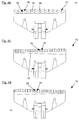
- FIG. 4 shows four further examples of hair transport elements 10.
- the transport teeth 12 of the hair transport member 10 in addition to a central tooth 26 sawteeth 32, which each have a steep flank 34 and a flat edge 36.
- the steep flanks 34 of the saw teeth 32 which are arranged to the left of the central tooth 26, point to the left, while the steep flanks 34, the saw teeth 32, which are arranged to the right of the central tooth 26, point to the right.
- FIG. 4b shows a Haartransportelement 10, similar to FIG. 4a
- hair-transport elements 10 which dispose the cut-off hairs 14 in one direction only.
- Figure 4c shows a Haartransportelement 10, without central tooth 26, in which the hair is thrown to the left.
- FIG. 4d shows a corresponding hair transport element 10, in which the hair is thrown off to the right.
- the transport toothing 12 in both cases runs obliquely to the base line 16, namely from left to right away from the base line 16, when the hairs are thrown off to the left, as shown in FIG Figure 4c is shown, and from left to right on the Bottom line 16 down to, if, in the case of FIG. 4d hair is thrown off to the right.
- An oblique course of the transport teeth 12 relative to the base line 16 corresponds to an oblique course of the transport teeth 12 relative to the cutting edge 18 of the hair clipper.
- This has the advantage that the hair thrown to the left or right is not repeatedly accelerated to teeth 32 of the transport teeth 12 in the discharge direction and thus ensures a distributed over a wider cross-sectional area hair shedding.
- the teeth 32 arranged on the right at the transport toothing 12 are arranged closer to the cutting edge 18 of the hair clipper than the teeth 36 arranged on the left on the transport toothing 12, as in FIG Figure 4c is shown.
- the teeth 32 arranged on the left on the transport toothing 12 are arranged closer to the cutting edge 18 of the hair clipper than the teeth 36 arranged on the right on the transport teeth 12, as seen in FIG. 4d becomes apparent.
- FIG. 5 shows a Haartransportelement 10 in a schematic representation with a further formation of the transport teeth 12.
- the saw teeth 32 are mirror-symmetrical to a central axis 37, which is also referred to as a mirror axis 37 and which passes through the central tooth 26, respectively.
- the left of the central tooth 26 arranged in a first section 38 sawteeth 32 are directed with their flat edges 36 in the direction of the central axis 37 of the hair clipper 1 and point with their steep flanks 34 to the left, away from the central axis 37.
- the right of the central tooth 26 arranged in a second section 40 sawteeth 32 are with their flat Flanks 36 directed toward the central axis 37 of the hair clipper 1 and point with their steep flanks 34 to the right, away from the central axis 37.
- the dashed lines shown envelope 21 limits and outlines the transport teeth 12.
- the envelope 21 encloses the teeth 26, 32 of the transport teeth 12 convex.
- the cutting edge 18 of the doctor blade 8 shown in dashed lines runs at a distance from the leading edge 20 of the hair transport element 10 and thus to the first section of the envelope 21.
- FIG. 6 shows a concave-convex envelope 21, which encloses the teeth 26, 32 of the transport teeth 12.
- the teeth of the feed teeth may be formed so that the tangential angles of the flat flanks are reduced from the baseline towards the tip of the single tooth until, for example, they have an angle of nearly zero degrees with the baseline.
- sawtooth shaped tooth profiles are to be referred to in this document as "sawtooth”.
Landscapes
- Life Sciences & Earth Sciences (AREA)
- Forests & Forestry (AREA)
- Engineering & Computer Science (AREA)
- Mechanical Engineering (AREA)
- Dry Shavers And Clippers (AREA)
- Scissors And Nippers (AREA)
Description
- Die vorliegende Erfindung betrifft einen Schneidsatz für eine Haarschneidemaschine nach dem Oberbegriff des Patentanspruchs 1, eine Haarschneidemaschine nach dem Oberbegriff des Patentanspruchs 11, sowie ein Haartransportelement nach dem Oberbegriff des Patentanspruchs 12.
- Haarschneidemaschinen sind im Stand der Technik in einer Vielzahl von Ausführungen bekannt. So beschreibt beispielsweise die
DE 60 2005 003 368 T2 ein Haarschneidegerät mit einem Gehäuse und mindestens einer Schneideinheit, die ein feststehendes Schneidbauteil und ein angetriebenes Schneidbauteil umfasst, das in Bezug auf das feststehende Schneidbauteil eine Hin- und Herbewegung ausführt. - Auch Haarschneidemaschinen mit mehreren Schneideinheiten sind im Stand der Technik bekannt. So offenbart beispielsweise die
DE 20 2013 103 187 U1 eine Haarschneidmaschine mit zwei Schneideinheiten. - In der
DE 10 2011 076 577 B3 ist eine Schneidsatzaufnahme für eine Haarschneidemaschine offenbart, mit einer Aufnahmebasis, die an der Haarschneidemaschine befestigbar ist und einem schwenkbar an der Aufnahmebasis gelagerten Aufnahmeschenkel, an dem ein auswechselbarer Schneidsatz anordnenbar ist, wobei ein zwischen einer Schwenkstellung und einer Blockierstellung bewegbares Sperrelement vorgesehen ist, das geeignet ausgebildet ist, eine Schwenkbewegung des Aufnahmeschenkels in Richtung der Aufnahmebasis ohne an dem Aufnahmeschenkel angeordneten Schneidsatz zu blockieren. - Eine Haarschneidemaschine mit einem auswechselbaren Schneidsatz, bestehend zumindest aus einem Scherkamm und einem im Wesentlichen parallel zur Vorderkante des Scherkamms über einen Mitnehmer in Querrichtung oszillierend antreibbaren Schermesser, sowie einer Schnittlängenverstelleinrichtung, bestehend aus einem Betätigungselement, das an einem Gehäuse der Haarschneidemaschine angelenkt ist und auf den Schneidsatz derart einwirkt, daß eine relative Verschiebung zwischen dem Scherkamm und dem Schermesser in Längsrichtung möglich ist, wird beispielsweise in der
DE 10 2009 015 276 A1 offenbart. - Die bekannten Haarschneidemaschinen und Schneidsätze für Haarschneidemaschinen weisen jedoch einen gravierenden Nachteil auf:
- So kommt es beim Schneiden von Haaren mit den im Stand der Technik bekannten Schneidsätzen für Haarschneidemaschinen, je nach Schneidposition zu einer Anhäufung von Haarabschnitten auf der Haarschneidemaschine. Diese Anhäufung von Haarabschnitten versperrt zum einen die Sicht auf den Schneidbereich und verschlechtert zum anderen die Zufuhr noch nicht geschnittener Haare. Der Friseur muss daher nach jeder Anhäufung von Haaren die Maschine zur Seite kippen, bzw. die Haare vom Schneidsatz der Maschine abschütteln. Dies ist insbesondere dann lästig, wenn ein letzter Haarfeinschnitt erfolgen soll.
- Aufgabe der vorliegenden Erfindung ist es daher, einen Schneidsatz für eine Haarschneidemaschine bereitzustellen, der diesen Nachteil nicht aufweist, sowie eine Haarschneidemaschine mit einem solchen Schneidsatz bereitzustellen.
- Diese Aufgabe wird gelöst durch einen Schneidsatz nach Patentanspruch 1, durch eine Haarschneidemaschine nach Patentanspruch 11, sowie durch ein Haartransportelement nach Patentanspruch 12. Vorteilhafte Ausführungsformen sind in den jeweiligen Unteransprüchen angegeben.
- Der erfindungsgemäße Schneidsatz weist zumindest einen feststehenden oder einen verstellbaren Scherkamm und ein im Wesentlichen parallel zur Vorderkante des Scherkamms in Querrichtung oszillierend antreibbares Schermesser auf, sowie ein Haartransportelement, welches eine Transportzahnung mit Zähnen aufweist, die im Wesentlichen entlang der und beabstandet zur Schneidkante des Schermessers angeordnet sind. Das Haartransportelement kann dabei Teil des Schneidsatzes sein, beispielsweise wenn der gesamte Schneidsatz austauschbar ist. Das Schermesser ist zwischen dem Scherkamm und dem Haartransportelement angeordnet, wobei die Schneidkante des Schermessers die von den Spitzen der Zähne der Transportzahnung gebildete Vorderkante des Haartransportelements überragt. Bei einem verstellbaren Scherkamm bleibt der Abstand der Haartransporteinrichtung relativ zu einem Gehäuse der Haarschneidemaschine gleich.
- Vorzugsweise ist der erfindungsgemäße Schneidsatz als ein austauschbarer Kopf einer Haarschneidemaschine ausgebildet, bei welchem vorteilhafterweise Schermesser, Scherkamm und Haartransportelement bereits miteinander verbunden sind, so daß er gegen einen gewöhnlichen im Stand der Technik bekannten Schneidsatz, der kein Haartransportelement aufweist, schnell ausgetauscht werden kann.
- Die Transportzahnung weist vorteilhafterweise ein im Wesentlichen sägezahnförmiges Querschnittsprofil auf. Unter einem "im Wesentlichen sägezahnförmigen Profil" soll hier ein Querschnittsprofil verstanden werden, bei dem die Zähne jeweils eine Steilflanke und eine flache Flanke aufweisen. Die Steilflanke ist dabei dadurch bestimmt, daß ihr Anstiegswinkel relativ zur Grundlinie der Transportzahnung, also zu der Linie, auf und entlang der die Zähne der Transportzahnung angeordnet sind, steiler ist, als der Anstiegswinkel zwischen der flachen Flanke und der Grundlinie. Die Spitzen der Zähne können dabei auch abgeflacht und / oder abgerundet sein. Die Steilflanken der Zähne weisen vorzugsweise Winkel von im Wesentlichen 90° relativ zur Grundlinie auf, wobei der Begriff "im Wesentlichen 90°" in diesem Zusammenhang Winkel zwischen 80° und 100° einschließen soll.
- Das Haartransportelement ist entweder fest mit dem Schermesser verbunden, wobei es vorzugsweise flächig mit dem Schermesser verbunden ist, oder es wirkt mit der Bewegung des Schermessers relativ zum Scherkamm über ein Verbindungselement zusammen. Das Haartransportelement kann dann beispielsweise über einen Mitnehmer mit dem Schermesser oszillierend antreibbar verbunden sein. Dadurch, daß sich das Schermesser mit dem Haartransportelement beim Schneiden der Haare schnell auf dem Scherkamm hin und her bewegt, werden die Haare abgeschnitten und an den sich ebenfalls hin- und her bewegenden Steilflanken der Sägezähne des Haartransportelements in Richtung der Hin- und Her-Bewegung des Schermessers, also in Querrichtung zur Schnittrichtung, beschleunigt, von der Haarschneidemaschine wegbewegt und entfernt. Die Schnittrichtung ist eine Richtung senkrecht zur Schneidkante des Schermessers.
- Da entlang der gesamten Schneidkante Haare abgeschnitten werden, erstreckt sich die Transportzahnung in vorteilhaften Ausbildungen im Wesentlichen entlang der gesamten Schneidkante des Schermessers, so daß die Zähne der Transportzahnung im Wesentlichen entlang der gesamten Schneidkante des Schermessers verlaufend an dem Haartransportelement angeordnet sind, um möglichst alle abgeschnittenen Haare zu erfassen und von der Haarschneidemaschine zu entfernen.
- Damit die abgeschnittenen Haare nicht nur in eine der beiden Querrichtungen der Hin- und Her-Bewegung des Schermessers relativ zum Scherkamm beschleunigt werden, sondern ein Teil der Haarabschnitte in die eine Querrichtung und der andere Teil der Haarabschnitte in die andere Querrichtung beschleunigt wird, so daß die Haarabschnitte sowohl nach links, als auch nach rechts von der Haarschneidemaschine abgeworfen werden, weist die Transportzahnung einen ersten und einen zweiten Teilabschnitt auf, wobei die Steilflanken der Sägezähne des ersten Teilabschnitts der Transportzahnung und die Steilflanken der Sägezähne des zweiten Teilabschnitts der Transportzahnung in im Wesentlichen einander entgegengesetzte Richtungen weisen. Der Winkel zwischen den beiden im Wesentlichen einander entgegengesetzten Richtungen beträgt vorzugsweise zwischen 160° und 200°.
- In einer besonders bevorzugten Ausführungsform sind die Sägezähne im ersten Teilabschnitt der Transportzahnung spiegelsymmetrisch zu den Sägezähnen im zweiten Teilabschnitt der Transportzahnung ausgebildet, wobei die Spiegelachse senkrecht zur Grundlinie der Transportzahnung und mittig durch die Transportzahnung verläuft, so daß der erste Teilabschnitt und der zweite Teilabschnitt zur Bildung der Transportzahnung spiegelsymmetrisch so aneinander grenzen, daß die Steilflanken der Zähne der Transportzahnung in einander entgegengesetzte Richtungen weisen. Dadurch können abgeschnittene Haare zu beiden Seiten der Haarschneidemaschine abgeworfen werden.
- Die Transportzahnung weist in einer vorteilhaften Ausbildung mittig einen Mittelzahn auf, der beispielsweise dreieckartig oder dreieckig ausgebildet sein kann, wobei er bevorzugt zwei Steilflanken aufweist. Der Mittelzahn kann aber beispielsweise auch rechteckig oder trapezförmig ausgebildet sein. Im Falle einer spiegelsymmetrischen Anordnung der Zähne der Transportzahnung erstreckt sich die Spiegelachse durch die Mitte des Mittelzahns hindurch, so daß beide Teilabschnitte der Transportzahnung jeweils einen halben Mittelzahn aufweisen.
- Die Zähne der Transportzahnung weisen im Wesentlichen dreieckförmige oder dreieckige Querschnittsprofile auf.
- Die Hüllkurve der Transportzahnung weist im Wesentlichen vier miteinander verbundene Abschnitte auf, die die Transportzahnung umschließen bzw. umhüllen. Der erste Abschnitt der Hüllkurve wird gebildet durch die Vorderkante des Haartransportelements, welche durch die Gesamtzahl der kürzesten Verbindungen zwischen einander benachbarter Spitzen einzelner Zähne der Transportzahnung definiert ist. Der zweite Abschnitt wird gebildet durch die Grundlinie der Transportzahnung, also durch die Linie, auf der die den Spitzen der Zähne gegenüber liegenden Basisflächen der Zähne angeordnet sind. Der dritte und vierte Abschnitt der Hüllkurve wird von den beiden seitlichen Begrenzungen der Transportzahnung gebildet.
- Die Spitzen der Zähne der Transportzahnung spannen somit den ersten Teil der Hüllkurve auf. Vorteilhafterweise begrenzt der erste Teil der Hüllkurve die Transportzahnung konvex, wobei auch eine geradlinige Begrenzung in dieser Offenbarung als eine konvexe Begrenzung bezeichnet werden soll. Bevorzugt ist die Transportzahnung dabei so ausgebildet, daß die Hüllkurve der Transportzahnung die gesamte Transportzahnung konvex umschließt.
- In einer besonders bevorzugten Ausführungsform verläuft die Vorderkante des Haartransportelements parallel zur Schneidkante des Schermessers. Der Abstand zwischen der Vorderkante des Haartransportelements, also der Vorderkante der Transportzahnung und der Schneidkante des Schermessers beträgt bevorzugt zwischen 1 mm und 5 mm. So kann in optimaler Weise dafür gesorgt werden, daß die abgeschnittenen Haare von dem Haartransportelement von der Mitte der Haarschneidemaschine seitlich wegbewegt werden.
- Der Abstand zwischen der Vorderkante des Scherkamms und der Schneidkante des Schermessers ist vorzugsweise mit einem Betätigungselement einstellbar, das entweder an den Schneidsatz gekoppelt ist und somit Teil des Schneidsatzes sein kann oder an die Haarschneidemaschine. Bevorzugt bleibt die relative Position der Schneidkante des Schermessers zu der Vorderkante des Haartransportelements gleich, wenn der Abstand zwischen der Vorderkante des Scherkamms und der Schneidkante des Schermessers geändert wird, es sind jedoch auch Ausbildungen vorstellbar, bei denen dieser Abstand variiert werden kann, um, je nach Anforderung an die Länge der Haarabschnitte ein optimales Abwerfen der Haare von der Haarschneidmaschine zu ermöglichen.
- Die erfindungsgemäße Haarschneidemaschine ist bevorzugt elektrisch angetrieben. Sie weist, neben dem erfindungsgemäßen Schneidsatz, vorteilhafterweise ein Gehäuse auf, das beispielsweise mit dem Scherkamm fest verbunden ist und einen Elektromotor zum oszillierenden Antreiben des Schermessers umschließt. Sie weist vorzugsweise weiterhin einen Mitnehmer auf, der mit dem Elektromotor und dem Schermesser so verbunden ist, daß er das Schermesser oszillierend, bevorzugt in Querrichtung zur Schnittrichtung, antreibt, wenn der Elektromotor eingeschaltet ist. Der Scherkamm kann optional an dem Gehäuse befestigt sein. Vorteilhafterweise ist jedoch das Haartransportelement entweder mit dem Schermesser fest verbunden oder mit dem Schermesser so verbunden, daß sich das Haartransportelement mit dem Schermesser mitbewegt, wenn das Schermesser oszillierend angetrieben wird, damit die Anhäufung der Haarabschnitte nicht die Sicht auf den Schneidebereich versperrt und die Zufuhr zu schneidender Haare nicht verschlechtert oder blockiert. Das Haartransportelement des Schneidsatzes der Haarschneidemaschine weist in einer möglichen Ausführungsform einen Eingriff zur Aufnahme des Mitnehmers auf.
- Die in der nachfolgenden Beschreibung verwendeten Bezeichnungen, wie oben, unten, links und rechts und ähnliches beziehen sich auf die Figuren und sollen in keiner Weise einschränkend sein, auch dann nicht, wenn sie sich auf bevorzugte Ausführungsformen beziehen. Die Formulierung "im Wesentlichen" bezogen auf Winkel und Anordnungen, soll Abweichungen bis 20°, vorzugsweise bis 10° umfassen, sofern nicht andere Angaben gemacht werden.
- Die Erfindung wird nachfolgend anhand von Zeichnungen näher erläutert. Es zeigen:
- Fig. 1
- eine Haarschneidemaschine,
- Fig. 2
- einen Schneidsatz einer Haarschneidemaschine mit einem erfindungsgemäßen Haartransportelement,
- Fig. 3
- ein Beispiel des erfindungsgemäßen Haartransportelements,
- Fig. 4
- vier weitere Beispiele erfindungsgemäßer Haartransportelemente,
- Fig. 5
- eine schematische Darstellung des erfindungsgemäßen Haartransportelements,
- Fig. 6
- die Hüllkurve einer möglichen Transportzahnung relativ zur Schneidkante des Schermessers.
-
Figur 1 zeigt eine Haarschneidemaschine 1 mit einem Schneidsatz 2, sowie einem Gehäuse 4, in welchem ein Elektromotor (nicht dargestellt) angeordnet ist. Der Elektromotor kann mit einem elektrischen Schalter 6 ein- oder ausgeschaltet werden. -
Figur 2 zeigt einen Teil des Schneidsatzes 2 vonFigur 1 mit einem Schermesser 8 und einem Haartransportelement 10, welches eine Transportzahnung 12 aufweist, die vorliegend einstückig mit dem Haartransportelement 10 ausgebildet ist. Das Haartransportelement 10 ist fest mit dem Schermesser 8 verbunden und bewegt sich mit diesem hin und her, sodaß die Transportzahnung 12 abgeschnittene Haare 14 nach links und nach rechts abwirft und so die Haarabschnitte 14 automatisch vom Schneidsatz 2 wegbewegt und sowohl die Sicht auf die noch abzuschneidenden Haare freigibt, als auch die Zufuhr neuer Haarabschnitte erleichtert. - Das Haartransportelement 10 weist eine Grundlinie 16 auf, auf der die Transportzahnung 12 sitzt, bzw. auf der die einzelnen Zähne der Transportzahnung 12 angeordnet sind. Parallel zur Schneidkante 18 des Schermessers 8, die ebenfalls als gestrichelte Linie in
Figur 2 dargestellt ist, ist die Vorderkante 20 des Haartransportelements 12 angeordnet und als gestrichelte Linie 20 dargestellt. Die Vorderkante 20 des Haartransportelements 12 definiert zusammen mit der Grundlinie 16 der Transportzahnung 12 und den beiden seitlichen Begrenzungen der Transportzahnung 12 eine Hüllkurve 21, welche die Transportzahnung 12 konvex umhüllt. Der inFigur 2 dargestellte Schneidsatz 2 weist weiterhin einen Scherkamm 24 auf, dessen Vorderkante 22 ebenfalls als gestrichelte Linie angedeutet ist. - In
Figur 3 ist ein Beispiel eines Haartransportelements 10 nochmals vergrößert dargestellt. Die Transportzahnung 12 weist einen Mittelzahn 26 auf, zwei Durchbohrungen 28, die der Befestigung des Haartransportelements 10 an dem Schermesser 8 dienen, sowie einen Eingriff 30 für einen Mitnehmer (nicht dargestellt). Die Haare 14, die rechts von dem Mittelzahn 26 des Haartransportelements 10 abgeschnitten werden, werden durch die Hin- und Herbewegung des Haartransportelements 10, die mit der Hin- und Herbewegung des Schermessers 8 relativ zu dem Scherkamm 24 korreliert ist, von Sägezähnen 32, die rechts von dem Mittelzahn 26 angeordnet sind, nach rechts transportiert und in Richtung der rechten Seite des Haartransportelements 10 abgeworfen. Die Haare 14, die links von dem Mittelzahn 26 von dem Schermesser 8 abgeschnitten werden, werden von den Sägezähnen 32, die links vom Mittelzahn 26 an dem Haartransportelement 10 angeordnet sind, nach links transportiert und in Richtung der linken Seite des Haartransportelements 10 abgeworfen. -
Figur 4 zeigt vier weitere Beispiele von Haartransportelementen 10. - Wie insbesondere in
Figur 4a zu sehen ist, weist die Transportzahnung 12 des Haartransportelements 10 neben einem Mittelzahn 26 Sägezähne 32 auf, welche jeweils eine Steilflanke 34 und eine flache Flanke 36 aufweisen. Die Steilflanken 34 der Sägezähne 32, die links vom Mittelzahn 26 angeordnet sind, weisen nach links, während die Steilflanken 34, der Sägezähne 32, die rechts vom Mittelzahn 26 angeordnet sind, nach rechts weisen. Dadurch, daß die Steilflanken 34 an beiden Seiten der Transportzahnung 12 jeweils nach außen, also in im wesentlichen entgegengesetzte Richtungen weisen, kann sichergestellt werden, daß abgeschnittene Haare 14, die an der linken Seite der Haarschneidemaschine 1 abgeschnitten werden, durch die Hin- und Herbewegung des Haartransportelements 10 nach links abgeworfen werden, während Haare 14, die an der rechten Seite der Haarschneidemaschine 1 abgeschnitten werden, nach rechts abgeworfen werden. -
Figur 4b zeigt ein Haartransportelement 10, ähnlich wieFigur 4a , mit einem Mittelzahn 26 und Sägezähnen 32, die Steilflanken 34 und flachen Flanken 36 aufweisen, jedoch weniger und dafür größere Sägezähne 32. Es ist jedoch auch möglich, Haartransportelemente 10 bereitzustellen, die die abgeschnittenen Haare 14 nur in eine Richtung abwerfen. -
Figur 4c zeigt ein Haartransportelement 10, ohne Mittelzahn 26, bei dem die Haare nach links abgeworfen werden.Figur 4d zeigt ein entsprechendes Haartransportelement 10, bei welchem die Haare nach rechts abgeworfen werden. Die Transportzahnung 12 verläuft in beiden Fällen schräg zur Grundlinie 16, und zwar von links nach rechts von der Grundlinie 16 weg nach oben, wenn die Haare nach links abgeworfen werden, wie dies inFigur 4c dargestellt ist, und von links nach rechts auf die Grundlinie 16 nach unten zu, wenn, im Fall vonFigur 4d , die Haare nach rechts abgeworfen werden. - Ein schräger Verlauf der Transportzahnung 12 relativ zur Grundlinie 16 entspricht einem schrägen Verlauf der Transportzahnung 12 relativ zur Schneidkante 18 der Haarschneidmaschine. Dies hat den Vorteil, daß die nach links oder rechts abgeworfenen Haare nicht mehrfach an Zähnen 32 der Transportzahnung 12 in Abwurfrichtung beschleunigt werden und sorgt so für einen über eine breitere Querschnittsfläche verteilten Haarabwurf. Bei einem Haartransport nach links sind die rechts an der Transportzahnung 12 angeordneten Zähne 32 näher an der Schneidkante 18 der Haarschneidemaschine angeordnet, als die links an der Transportzahnung 12 angeordneten Zähne 36, wie in
Figur 4c dargestellt ist. - Bei einem Transport abgeschnittener Haare 14 nach rechts sind die links an der Transportzahnung 12 angeordneten Zähne 32 näher an der Schneidkante 18 der Haarschneidemaschine angeordnet, als die rechts an der Transportzahnung 12 angeordneten Zähne 36, wie aus
Figur 4d ersichtlich wird. -
Figur 5 zeigt ein Haartransportelement 10 in schematischer Darstellung mit einer weiteren Ausformung der Transportzahnung 12. Die Sägezähne 32 sind spiegelsymmetrisch zu einer Mittelachse 37, die auch als Spiegelachse 37 bezeichnet wird und die durch den Mittelzahn 26 verläuft, angeordnet. Die links vom Mittelzahn 26 in einem ersten Teilabschnitt 38 angeordneten Sägezähne 32 sind mit ihren flachen Flanken 36 in Richtung auf die Mittelachse 37 der Haarschneidemaschine 1 gerichtet und weisen mit ihren Steilflanken 34 nach links, von der Mittelachse 37 weg. Die rechts vom Mittelzahn 26 in einem zweiten Teilabschnitt 40 angeordneten Sägezähne 32 sind mit ihren flachen Flanken 36 in Richtung auf die Mittelachse 37 der Haarschneidemaschine 1 gerichtet und weisen mit ihren Steilflanken 34 nach rechts, von der Mittelachse 37 weg. Die gestrichelt dargestellte Hüllkurve 21 begrenzt und umrandet die Transportzahnung 12. Die Hüllkurve 21 umschließt dabei die Zähne 26, 32 der Transportzahnung 12 konvex. Die inFigur 5 gestrichelt dargestellte Schneidkante 18 des Schermessers 8 verläuft beabstandet zu der Vorderkante 20 des Haartransportelements 10 und somit zu dem ersten Abschnitt der Hüllkurve 21. -
Figur 6 zeigt eine konkav-konvex ausgebildete Hüllkurve 21, welche die Zähne 26, 32 der Transportzahnung 12 umschließt. Der erste Abschnitt der Hüllkurve 21, verläuft benachbart zur Schneidkante 18 und begrenzt die Transportzahnung 12 dabei konvex so, daß die Spitzen der Zähne 32, 26 die mehr in der Mitte der Transportzahnung 12 angeordnet sind, einen geringeren Abstand zur Schneidkante 18 aufweisen, als die Zähne 26, die näher an den beiden Rändern der Transportzahnung 12 angeordnet sind. Dies hat den Vorteil, daß Haarabschnitte 14, die bereits von einer Steilflanke 34 eines Zahns 26, 32 in eine Richtung seitlich nach außen bewegt worden sind, nicht durch eine flache Flanke eines Zahns 32 eine erneute Richtungsänderung erfahren. Dadurch können, ähnlich wie bei dem Beispiel inFigur 5 , bei welchem die Hüllkurve 21 die gesamte Transportzahnung 12 konvex umschließt, Haarabschnitte 14 von der Haarschneidemaschine 1 rasch und effektiv entfernt werden. Die Grundlinie 16 der Transportzahnung 12, also der zweite Abschnitt der Hüllkurve 21, begrenzt die Transportzahnung 12 in diesem Beispiel konkav. - Die Erfindung wurde anhand bevorzugter Ausführungsbeispiele erläutert, ohne auf diese Beispiele beschränkt zu sein. Einzelne Merkmale der jeweils dargestellten Ausführungsbeispiele sind auch untereinander kombinierbar oder mit anderen, gleichwirkenden Merkmalen austauschbar, sofern Kompatibilität vorliegt. So können beispielsweise die Zähne der Transportzahnung so ausgebildet sein, daß sich die Tangentialwinkel der flachen Flanken von der Grundlinie aus in Richtung auf die Spitze des einzelnen Zahns hin verringern, bis sie beispielsweise mit der Grundlinie einen Winkel von nahezu Null Grad aufweisen. Auch derart geformte Zahnprofile sollen in dieser Schrift als "sägezahnförmig" bezeichnet werden.
-
- 1
- Haarschneidemaschine
- 2
- Schneidsatz
- 4
- Gehäuse
- 6
- elektrischer Schalter
- 8
- Schermesser
- 10
- Haartransportelement
- 12
- Transportzahnung
- 14
- Haare, Haarabschnitte
- 16
- Grundlinie der Transportzahnung
- 18
- Schneidkante
- 20
- Vorderkante des Haartransportelements
- 21
- Hüllkurve
- 22
- Vorderkante des Scherkamms
- 24
- Scherkamm
- 26
- Zahn, Mittelzahn
- 28
- Durchbohrungen
- 30
- Eingriff
- 32
- Zahn, Sägezahn
- 34
- Steilflanke
- 36
- flache Flanke
- 37
- Mittelachse
- 38
- erster Teilabschnitt
- 40
- zweiter Teilabschnitt
Claims (12)
- Schneidsatz (2) einer Haarschneidemaschine (1), aufweisend- einen, vorzugsweise feststehenden, Scherkamm (24),- ein im wesentlichen parallel zur Vorderkante (22) des Scherkamms (24) in Querrichtung oszillierend antreibbares Schermesser (8),dadurch gekennzeichnet, dass der Schneidsatz ein Haartransportelement (10) aufweist, das eine Transportzahnung (12) mit nebeneinander angeordneten Zähnen (26, 32) aufweist, welche im Wesentlichen entlang der Schneidkante des Schermessers (8), beabstandet zur Schneidkante (18) des Schermessers (8) angeordnet sind, wobei das Schermesser (8) zwischen dem Scherkamm (24) und dem Haartransportelement (10) angeordnet ist und wobei die Schneidkante (18) des Schermessers (8) die Vorderkante (20) des Haartransportelements (10) überragt.
- Schneidsatz (2) nach Anspruch 1,
dadurch gekennzeichnet, dass die Transportzahnung (12) ein im Wesentlichen sägezahnförmiges Profil aufweist, wobei die Sägezähne (32) des sägezahnförmigen Profils jeweils eine Steilflanke (34) und eine flache Flanke (36) aufweisen. - Schneidsatz (2) nach einem der vorigen Ansprüche,
dadurch gekennzeichnet, dass die Transportzahnung (12) des Haartransportelements (10) im Wesentlichen entlang der gesamten Schneidkante (18) des Schermessers (8) verlaufend an dem Haartransportelement (10) angeordnet ist. - Schneidsatz (2) nach einem der vorigen Ansprüche,
dadurch gekennzeichnet, dass die Vorderkante (20) des Haartransportelements (10) im Wesentlichen parallel zur Schneidkante (18) des Schermessers (8) ist. - Schneidsatz (2) nach einem der vorigen Ansprüche,
dadurch gekennzeichnet, dass die Spitzen der Zähne (26, 32) der Transportzahnung (12) so relativ zueinander angeordnet sind, daß sie einen ersten Teilabschnitt einer Hüllkurve (21) definieren, der die Transportzahnung (12) konvex begrenzt. - Schneidsatz (2) nach einem der vorigen Ansprüche,
dadurch gekennzeichnet, dass das Haartransportelement (10) mit dem Schermesser (8) fest, vorzugsweise flächig, verbunden ist oder daß das Haartransportelement (10) über einen Mitnehmer mit dem Schermesser (8) oszillierend antreibbar ist. - Schneidsatz (2) nach einem der vorigen Ansprüche,
dadurch gekennzeichnet, dass die Transportzahnung (12) einen ersten Teilabschnitt (38) und einen zweiten Teilabschnitt (40) aufweist, wobei die Steilflanken (34) der Sägezähne (32) des ersten Teilabschnitts (38) der Transportzahnung (12) und die Steilflanken (34) der Sägezähne (32) des zweiten Teilabschnitts (40) der Transportzahnung (12) in im Wesentlichen einander entgegengesetzte Richtungen weisen. - Schneidsatz (2) nach einem der vorigen Ansprüche,
dadurch gekennzeichnet, dass der erste Teilabschnitt (38) der Transportzahnung (12) spiegelsymmetrisch zu dem zweiten Teilabschnitt (40) der Transportzahnung (12) ausgebildet ist. - Schneidsatz (2) nach einem der vorigen Ansprüche,
dadurch gekennzeichnet, dass die Transportzahnung (12) mittig einen Mittelzahn (26) mit vorzugsweise zwei Steilflanken (34) aufweist. - Schneidsatz (2) nach einem der vorigen Ansprüche,
dadurch gekennzeichnet, dass der Abstand zwischen der Vorderkante (22) des Scherkamms (24) und der Schneidkante (18) des Schermessers (8), vorzugsweise mit einem Betätigungselement, einstellbar ist, wobei die relative Position der Schneidkante (18) des Schermessers (8) zu der Vorderkante (21) des Haartransportelements (10) gleich bleibt, wenn der Abstand zwischen der Vorderkante (22) des Scherkamms (24) und der Schneidkante (18) des Schermessers (8) geändert wird. - Haarschneidemaschine (1), aufweisend- einen Schneidsatz nach einem der Ansprüche 1 bis 10,- ein Gehäuse (4), das einen Elektromotor zum oszillierenden Antreiben des Schermessers (8) umschließt,- sowie einen Mitnehmer, der mit dem Elektromotor und dem Schermesser (8) so verbunden ist, daß er das Schermesser (8) oszillierend antreibt, wenn der Elektromotor eingeschaltet ist,dadurch gekennzeichnet, dass das Haartransportelement (10) entweder mit dem Schermesser (8) fest verbunden ist, oder mit dem Schermesser (8) so verbunden ist, daß sich das Haartransportelement (10) mit dem Schermesser (8) mitbewegt, wenn das Schermesser (8) oszillierend angetrieben wird.
- Haartransportelement (10) eines Schneidsatzes (2) einer Haarschneidemaschine (1) nach Anspruch 11, aufweisend einen Eingriff (30) zur Aufnahme des Mitnehmers.
Priority Applications (1)
| Application Number | Priority Date | Filing Date | Title |
|---|---|---|---|
| PL16178236T PL3117972T3 (pl) | 2015-07-17 | 2016-07-06 | Zestaw tnący maszynki do ścinania włosów z elementem do transportowania włosów i maszynka do ścinania włosów z elementem do transportowania włosów |
Applications Claiming Priority (1)
| Application Number | Priority Date | Filing Date | Title |
|---|---|---|---|
| DE102015111690.1A DE102015111690A1 (de) | 2015-07-17 | 2015-07-17 | Schneidsatz einer Haarschneidemaschine mit Haartransportelement und Haarschneidemaschine mit Haartransportelement |
Publications (2)
| Publication Number | Publication Date |
|---|---|
| EP3117972A1 true EP3117972A1 (de) | 2017-01-18 |
| EP3117972B1 EP3117972B1 (de) | 2018-03-21 |
Family
ID=56360329
Family Applications (1)
| Application Number | Title | Priority Date | Filing Date |
|---|---|---|---|
| EP16178236.2A Active EP3117972B1 (de) | 2015-07-17 | 2016-07-06 | Schneidsatz einer haarschneidemaschine mit haartransportelement und haarschneidemaschine mit haartransportelement |
Country Status (9)
| Country | Link |
|---|---|
| US (1) | US10213931B2 (de) |
| EP (1) | EP3117972B1 (de) |
| CN (1) | CN106346518B (de) |
| DE (1) | DE102015111690A1 (de) |
| ES (1) | ES2674218T3 (de) |
| HU (1) | HUE038205T2 (de) |
| PL (1) | PL3117972T3 (de) |
| RU (1) | RU2661130C2 (de) |
| TR (1) | TR201808682T4 (de) |
Cited By (2)
| Publication number | Priority date | Publication date | Assignee | Title |
|---|---|---|---|---|
| US20210331338A1 (en) * | 2020-04-24 | 2021-10-28 | Wahl Gmbh | Cutting Set with Wave-shaped Cutting Edge |
| EP4678357A1 (de) | 2024-07-12 | 2026-01-14 | Wahl GmbH | Schneidsatz mit haartransportelement |
Families Citing this family (4)
| Publication number | Priority date | Publication date | Assignee | Title |
|---|---|---|---|---|
| USD813459S1 (en) * | 2015-10-07 | 2018-03-20 | Thomas James Sinnott | Hair clipper guide attachment |
| WO2023043629A1 (en) | 2021-09-14 | 2023-03-23 | Wahl Clipper Corporation | Hair clipper bladeset with variable rake angle array tooth geometry |
| US20230405854A1 (en) * | 2022-06-15 | 2023-12-21 | Wahl Clipper Corporation | Variable pitch, multiple root bladeset for hair cutting |
| DE102023129107B3 (de) | 2023-10-23 | 2025-01-23 | Wahl Gmbh | Schneidsatz für eine Haarschneidemaschine mit Staubnut |
Citations (7)
| Publication number | Priority date | Publication date | Assignee | Title |
|---|---|---|---|---|
| US2262388A (en) * | 1937-06-26 | 1941-11-11 | American Safety Razor Corp | Shaving device |
| US2325267A (en) * | 1940-09-27 | 1943-07-27 | Thomas J Murphy | Dry shaver cutter head |
| WO2006000935A1 (en) * | 2004-06-21 | 2006-01-05 | Koninklijke Philips Electronics N.V. | Hair cutting apparatus |
| US20090126201A1 (en) * | 2007-11-15 | 2009-05-21 | Wahl Clipper Corporation | Bladeset for a hair cutting apparatus |
| DE102009015276A1 (de) | 2009-04-01 | 2010-10-14 | Wahl Gmbh | Haarschneidemaschine mit auswechselbarem Schneidsatz und Schnittlängen-Verstelleinrichtung |
| DE102011076577B3 (de) | 2011-05-27 | 2012-06-06 | Wahl Gmbh | Schneidsatzaufnahme |
| DE202013103187U1 (de) | 2012-07-26 | 2013-07-26 | Specialife (Zhuhai) Co., Ltd. | Haarschneidmaschine mit zwei Schneideeinheiten |
Family Cites Families (16)
| Publication number | Priority date | Publication date | Assignee | Title |
|---|---|---|---|---|
| US1908385A (en) * | 1931-10-10 | 1933-05-09 | Wahl Clipper Corp | Clipper attachment |
| US1871700A (en) * | 1932-03-19 | 1932-08-16 | Chicago Flexible Shaft Co | Shearing machine |
| US2294713A (en) * | 1940-03-23 | 1942-09-01 | Allover Mfg Co | Electric hair clipper |
| US2704887A (en) * | 1951-03-15 | 1955-03-29 | Andis Clipper Co | Blade guiding and driving assembly for hair clippers and shavers |
| US3999295A (en) * | 1976-04-19 | 1976-12-28 | Sunbeam Corporation | Hair cutting apparatus |
| US5933964A (en) * | 1996-07-17 | 1999-08-10 | Wahl Clipper Corporation | Cutter blade for hair clippers |
| US6073350A (en) * | 1996-08-09 | 2000-06-13 | Wahl Clipper Corporation | Bladeset for hair clippers including blade with hair evacuation configuration |
| EP0886563B1 (de) * | 1996-12-13 | 2003-01-15 | Koninklijke Philips Electronics N.V. | Haarschneidesystem mit einer haarschneidevorrichtung und einer kammvorrichtung, die an der haarschneidevorrichtung befestigt werden kann und die zwei federbelastete kammabschnitte hat |
| EP0885094A1 (de) * | 1996-12-13 | 1998-12-23 | Koninklijke Philips Electronics N.V. | Haarschneidesystem mit einer haarschneidevorrichtung, die einen einstellknopf und einen einlaufknopf hat |
| RU56255U1 (ru) * | 2005-10-18 | 2006-09-10 | Виктор Николаевич Ючинский | Машинка для стрижки волос |
| DE102006058111A1 (de) * | 2006-12-09 | 2008-06-19 | Braun Gmbh | Schneideeinrichtung zum Schneiden von Haaren |
| CN201124487Y (zh) * | 2007-10-31 | 2008-10-01 | 张金河 | 多功能理发推剪用限位梳 |
| WO2010121941A2 (de) * | 2009-04-20 | 2010-10-28 | Aesculap Suhl Gmbh | Tierschermaschine |
| DE102011008314B4 (de) * | 2011-01-11 | 2017-07-13 | Wahl Gmbh | Haarschneidemaschine |
| JP2012228368A (ja) * | 2011-04-26 | 2012-11-22 | Panasonic Corp | バリカン |
| CN204295713U (zh) * | 2014-12-12 | 2015-04-29 | 燕山大学 | 收纳式理发器 |
-
2015
- 2015-07-17 DE DE102015111690.1A patent/DE102015111690A1/de not_active Withdrawn
-
2016
- 2016-07-06 HU HUE16178236A patent/HUE038205T2/hu unknown
- 2016-07-06 TR TR2018/08682T patent/TR201808682T4/tr unknown
- 2016-07-06 ES ES16178236.2T patent/ES2674218T3/es active Active
- 2016-07-06 PL PL16178236T patent/PL3117972T3/pl unknown
- 2016-07-06 EP EP16178236.2A patent/EP3117972B1/de active Active
- 2016-07-13 RU RU2016128410A patent/RU2661130C2/ru active
- 2016-07-15 CN CN201610559786.XA patent/CN106346518B/zh active Active
- 2016-07-18 US US15/212,746 patent/US10213931B2/en active Active
Patent Citations (8)
| Publication number | Priority date | Publication date | Assignee | Title |
|---|---|---|---|---|
| US2262388A (en) * | 1937-06-26 | 1941-11-11 | American Safety Razor Corp | Shaving device |
| US2325267A (en) * | 1940-09-27 | 1943-07-27 | Thomas J Murphy | Dry shaver cutter head |
| WO2006000935A1 (en) * | 2004-06-21 | 2006-01-05 | Koninklijke Philips Electronics N.V. | Hair cutting apparatus |
| DE602005003368T2 (de) | 2004-06-21 | 2008-09-11 | Koninklijke Philips Electronics N.V. | Haarschneidevorrichtung |
| US20090126201A1 (en) * | 2007-11-15 | 2009-05-21 | Wahl Clipper Corporation | Bladeset for a hair cutting apparatus |
| DE102009015276A1 (de) | 2009-04-01 | 2010-10-14 | Wahl Gmbh | Haarschneidemaschine mit auswechselbarem Schneidsatz und Schnittlängen-Verstelleinrichtung |
| DE102011076577B3 (de) | 2011-05-27 | 2012-06-06 | Wahl Gmbh | Schneidsatzaufnahme |
| DE202013103187U1 (de) | 2012-07-26 | 2013-07-26 | Specialife (Zhuhai) Co., Ltd. | Haarschneidmaschine mit zwei Schneideeinheiten |
Cited By (4)
| Publication number | Priority date | Publication date | Assignee | Title |
|---|---|---|---|---|
| US20210331338A1 (en) * | 2020-04-24 | 2021-10-28 | Wahl Gmbh | Cutting Set with Wave-shaped Cutting Edge |
| US11820030B2 (en) * | 2020-04-24 | 2023-11-21 | Wahl Gmbh | Cutting set with wave-shaped cutting edge |
| EP4678357A1 (de) | 2024-07-12 | 2026-01-14 | Wahl GmbH | Schneidsatz mit haartransportelement |
| DE102024119933A1 (de) * | 2024-07-12 | 2026-01-15 | Wahl Gmbh | Schneidsatz mit Haartransportelement |
Also Published As
| Publication number | Publication date |
|---|---|
| RU2661130C2 (ru) | 2018-07-11 |
| TR201808682T4 (tr) | 2018-07-23 |
| DE102015111690A1 (de) | 2017-01-19 |
| PL3117972T3 (pl) | 2018-08-31 |
| CN106346518B (zh) | 2018-07-17 |
| ES2674218T3 (es) | 2018-06-28 |
| HUE038205T2 (hu) | 2018-10-29 |
| EP3117972B1 (de) | 2018-03-21 |
| RU2016128410A (ru) | 2018-01-18 |
| US10213931B2 (en) | 2019-02-26 |
| CN106346518A (zh) | 2017-01-25 |
| US20170015010A1 (en) | 2017-01-19 |
Similar Documents
| Publication | Publication Date | Title |
|---|---|---|
| EP3117972B1 (de) | Schneidsatz einer haarschneidemaschine mit haartransportelement und haarschneidemaschine mit haartransportelement | |
| DE60204731T2 (de) | Klingenanordung für einen elektrischen Haarschneider | |
| DE102010006030B4 (de) | Frisiermesser | |
| DE19734423C2 (de) | Klingensatz für Haarschneidemaschinen mit einer Klinge mit einer Konfiguration zum Wegführen von Haar | |
| DE19730775C2 (de) | Verbesserte Schneidklingen für Haarschneidemaschinen | |
| DE3743181C2 (de) | ||
| DE3421465C2 (de) | ||
| EP2554038B1 (de) | Messeranordnung einer Heckenschere | |
| EP1497082B1 (de) | Scherkopf für ein haarschneidegerät | |
| DE202006007059U1 (de) | Schneideeinheit mit Schutzzähnen und Haarschneidevorrichtung | |
| WO2008141720A1 (de) | Schneideinrichtung zum schneiden von haaren | |
| EP0963280A1 (de) | Haarschneidemaschine mit schnittlängen-verstelleinrichtung | |
| EP1694475A1 (de) | Schneidkopf für eine elektrische haarschneidemaschine | |
| DE102009035232A1 (de) | Schneidsatz für Haarschneidemaschinen | |
| EP1528971B1 (de) | Haarschneidemaschine | |
| WO2001039936A1 (de) | Rasierapparat | |
| DE10302998B4 (de) | Schneidsatz für Haarschneidemaschinen mit einer Doppelparallel-Federführung | |
| EP1329151B1 (de) | Heckenschere | |
| DE102011008314A1 (de) | Haarschneidemaschine | |
| DE102011016618A1 (de) | Landwirtschaftliches Schneidwerk | |
| EP4039425B1 (de) | Klingensatz für eine haarschneidemaschine | |
| DE102008010444B4 (de) | Schneidsatz für eine Haarschneidemaschine | |
| DE102017106929B4 (de) | Frisiermesser | |
| DE102006001533B4 (de) | Schneidsatz für eine Haar- und/oder Bartschneidemaschine | |
| DE4400013C2 (de) | Schneidvorrichtung |
Legal Events
| Date | Code | Title | Description |
|---|---|---|---|
| PUAI | Public reference made under article 153(3) epc to a published international application that has entered the european phase |
Free format text: ORIGINAL CODE: 0009012 |
|
| STAA | Information on the status of an ep patent application or granted ep patent |
Free format text: STATUS: THE APPLICATION HAS BEEN PUBLISHED |
|
| AK | Designated contracting states |
Kind code of ref document: A1 Designated state(s): AL AT BE BG CH CY CZ DE DK EE ES FI FR GB GR HR HU IE IS IT LI LT LU LV MC MK MT NL NO PL PT RO RS SE SI SK SM TR |
|
| AX | Request for extension of the european patent |
Extension state: BA ME |
|
| STAA | Information on the status of an ep patent application or granted ep patent |
Free format text: STATUS: REQUEST FOR EXAMINATION WAS MADE |
|
| 17P | Request for examination filed |
Effective date: 20170119 |
|
| RBV | Designated contracting states (corrected) |
Designated state(s): AL AT BE BG CH CY CZ DE DK EE ES FI FR GB GR HR HU IE IS IT LI LT LU LV MC MK MT NL NO PL PT RO RS SE SI SK SM TR |
|
| STAA | Information on the status of an ep patent application or granted ep patent |
Free format text: STATUS: EXAMINATION IS IN PROGRESS |
|
| 17Q | First examination report despatched |
Effective date: 20170621 |
|
| GRAP | Despatch of communication of intention to grant a patent |
Free format text: ORIGINAL CODE: EPIDOSNIGR1 |
|
| STAA | Information on the status of an ep patent application or granted ep patent |
Free format text: STATUS: GRANT OF PATENT IS INTENDED |
|
| INTG | Intention to grant announced |
Effective date: 20171213 |
|
| GRAS | Grant fee paid |
Free format text: ORIGINAL CODE: EPIDOSNIGR3 |
|
| GRAA | (expected) grant |
Free format text: ORIGINAL CODE: 0009210 |
|
| STAA | Information on the status of an ep patent application or granted ep patent |
Free format text: STATUS: THE PATENT HAS BEEN GRANTED |
|
| AK | Designated contracting states |
Kind code of ref document: B1 Designated state(s): AL AT BE BG CH CY CZ DE DK EE ES FI FR GB GR HR HU IE IS IT LI LT LU LV MC MK MT NL NO PL PT RO RS SE SI SK SM TR |
|
| REG | Reference to a national code |
Ref country code: GB Ref legal event code: FG4D Free format text: NOT ENGLISH |
|
| REG | Reference to a national code |
Ref country code: CH Ref legal event code: EP |
|
| REG | Reference to a national code |
Ref country code: AT Ref legal event code: REF Ref document number: 980598 Country of ref document: AT Kind code of ref document: T Effective date: 20180415 |
|
| REG | Reference to a national code |
Ref country code: IE Ref legal event code: FG4D Free format text: LANGUAGE OF EP DOCUMENT: GERMAN |
|
| REG | Reference to a national code |
Ref country code: DE Ref legal event code: R096 Ref document number: 502016000741 Country of ref document: DE |
|
| REG | Reference to a national code |
Ref country code: RO Ref legal event code: EPE |
|
| REG | Reference to a national code |
Ref country code: ES Ref legal event code: FG2A Ref document number: 2674218 Country of ref document: ES Kind code of ref document: T3 Effective date: 20180628 |
|
| REG | Reference to a national code |
Ref country code: NL Ref legal event code: FP |
|
| PG25 | Lapsed in a contracting state [announced via postgrant information from national office to epo] |
Ref country code: CY Free format text: LAPSE BECAUSE OF FAILURE TO SUBMIT A TRANSLATION OF THE DESCRIPTION OR TO PAY THE FEE WITHIN THE PRESCRIBED TIME-LIMIT Effective date: 20180321 Ref country code: LT Free format text: LAPSE BECAUSE OF FAILURE TO SUBMIT A TRANSLATION OF THE DESCRIPTION OR TO PAY THE FEE WITHIN THE PRESCRIBED TIME-LIMIT Effective date: 20180321 Ref country code: HR Free format text: LAPSE BECAUSE OF FAILURE TO SUBMIT A TRANSLATION OF THE DESCRIPTION OR TO PAY THE FEE WITHIN THE PRESCRIBED TIME-LIMIT Effective date: 20180321 |
|
| REG | Reference to a national code |
Ref country code: LT Ref legal event code: MG4D |
|
| REG | Reference to a national code |
Ref country code: SE Ref legal event code: TRGR |
|
| REG | Reference to a national code |
Ref country code: NO Ref legal event code: T2 Effective date: 20180321 Ref country code: FR Ref legal event code: PLFP Year of fee payment: 3 |
|
| PG25 | Lapsed in a contracting state [announced via postgrant information from national office to epo] |
Ref country code: BG Free format text: LAPSE BECAUSE OF FAILURE TO SUBMIT A TRANSLATION OF THE DESCRIPTION OR TO PAY THE FEE WITHIN THE PRESCRIBED TIME-LIMIT Effective date: 20180621 Ref country code: RS Free format text: LAPSE BECAUSE OF FAILURE TO SUBMIT A TRANSLATION OF THE DESCRIPTION OR TO PAY THE FEE WITHIN THE PRESCRIBED TIME-LIMIT Effective date: 20180321 Ref country code: SE Free format text: LAPSE BECAUSE OF FAILURE TO SUBMIT A TRANSLATION OF THE DESCRIPTION OR TO PAY THE FEE WITHIN THE PRESCRIBED TIME-LIMIT Effective date: 20180321 Ref country code: LV Free format text: LAPSE BECAUSE OF FAILURE TO SUBMIT A TRANSLATION OF THE DESCRIPTION OR TO PAY THE FEE WITHIN THE PRESCRIBED TIME-LIMIT Effective date: 20180321 Ref country code: GR Free format text: LAPSE BECAUSE OF FAILURE TO SUBMIT A TRANSLATION OF THE DESCRIPTION OR TO PAY THE FEE WITHIN THE PRESCRIBED TIME-LIMIT Effective date: 20180622 |
|
| PG25 | Lapsed in a contracting state [announced via postgrant information from national office to epo] |
Ref country code: MT Free format text: LAPSE BECAUSE OF FAILURE TO SUBMIT A TRANSLATION OF THE DESCRIPTION OR TO PAY THE FEE WITHIN THE PRESCRIBED TIME-LIMIT Effective date: 20180321 |
|
| REG | Reference to a national code |
Ref country code: HU Ref legal event code: AG4A Ref document number: E038205 Country of ref document: HU |
|
| PG25 | Lapsed in a contracting state [announced via postgrant information from national office to epo] |
Ref country code: EE Free format text: LAPSE BECAUSE OF FAILURE TO SUBMIT A TRANSLATION OF THE DESCRIPTION OR TO PAY THE FEE WITHIN THE PRESCRIBED TIME-LIMIT Effective date: 20180321 Ref country code: AL Free format text: LAPSE BECAUSE OF FAILURE TO SUBMIT A TRANSLATION OF THE DESCRIPTION OR TO PAY THE FEE WITHIN THE PRESCRIBED TIME-LIMIT Effective date: 20180321 |
|
| PG25 | Lapsed in a contracting state [announced via postgrant information from national office to epo] |
Ref country code: SK Free format text: LAPSE BECAUSE OF FAILURE TO SUBMIT A TRANSLATION OF THE DESCRIPTION OR TO PAY THE FEE WITHIN THE PRESCRIBED TIME-LIMIT Effective date: 20180321 Ref country code: SM Free format text: LAPSE BECAUSE OF FAILURE TO SUBMIT A TRANSLATION OF THE DESCRIPTION OR TO PAY THE FEE WITHIN THE PRESCRIBED TIME-LIMIT Effective date: 20180321 |
|
| PG25 | Lapsed in a contracting state [announced via postgrant information from national office to epo] |
Ref country code: PT Free format text: LAPSE BECAUSE OF FAILURE TO SUBMIT A TRANSLATION OF THE DESCRIPTION OR TO PAY THE FEE WITHIN THE PRESCRIBED TIME-LIMIT Effective date: 20180723 |
|
| REG | Reference to a national code |
Ref country code: DE Ref legal event code: R097 Ref document number: 502016000741 Country of ref document: DE |
|
| PLBE | No opposition filed within time limit |
Free format text: ORIGINAL CODE: 0009261 |
|
| STAA | Information on the status of an ep patent application or granted ep patent |
Free format text: STATUS: NO OPPOSITION FILED WITHIN TIME LIMIT |
|
| PG25 | Lapsed in a contracting state [announced via postgrant information from national office to epo] |
Ref country code: DK Free format text: LAPSE BECAUSE OF FAILURE TO SUBMIT A TRANSLATION OF THE DESCRIPTION OR TO PAY THE FEE WITHIN THE PRESCRIBED TIME-LIMIT Effective date: 20180321 |
|
| 26N | No opposition filed |
Effective date: 20190102 |
|
| PG25 | Lapsed in a contracting state [announced via postgrant information from national office to epo] |
Ref country code: MC Free format text: LAPSE BECAUSE OF FAILURE TO SUBMIT A TRANSLATION OF THE DESCRIPTION OR TO PAY THE FEE WITHIN THE PRESCRIBED TIME-LIMIT Effective date: 20180321 Ref country code: LU Free format text: LAPSE BECAUSE OF NON-PAYMENT OF DUE FEES Effective date: 20180706 |
|
| REG | Reference to a national code |
Ref country code: BE Ref legal event code: MM Effective date: 20180731 |
|
| REG | Reference to a national code |
Ref country code: IE Ref legal event code: MM4A |
|
| PG25 | Lapsed in a contracting state [announced via postgrant information from national office to epo] |
Ref country code: IE Free format text: LAPSE BECAUSE OF NON-PAYMENT OF DUE FEES Effective date: 20180706 |
|
| PG25 | Lapsed in a contracting state [announced via postgrant information from national office to epo] |
Ref country code: SI Free format text: LAPSE BECAUSE OF FAILURE TO SUBMIT A TRANSLATION OF THE DESCRIPTION OR TO PAY THE FEE WITHIN THE PRESCRIBED TIME-LIMIT Effective date: 20180321 Ref country code: BE Free format text: LAPSE BECAUSE OF NON-PAYMENT OF DUE FEES Effective date: 20180731 |
|
| PG25 | Lapsed in a contracting state [announced via postgrant information from national office to epo] |
Ref country code: MK Free format text: LAPSE BECAUSE OF NON-PAYMENT OF DUE FEES Effective date: 20180321 |
|
| PG25 | Lapsed in a contracting state [announced via postgrant information from national office to epo] |
Ref country code: IS Free format text: LAPSE BECAUSE OF FAILURE TO SUBMIT A TRANSLATION OF THE DESCRIPTION OR TO PAY THE FEE WITHIN THE PRESCRIBED TIME-LIMIT Effective date: 20180721 |
|
| PGFP | Annual fee paid to national office [announced via postgrant information from national office to epo] |
Ref country code: FI Payment date: 20210726 Year of fee payment: 6 Ref country code: CZ Payment date: 20210831 Year of fee payment: 6 Ref country code: AT Payment date: 20210802 Year of fee payment: 6 Ref country code: FR Payment date: 20210730 Year of fee payment: 6 |
|
| PGFP | Annual fee paid to national office [announced via postgrant information from national office to epo] |
Ref country code: CH Payment date: 20210819 Year of fee payment: 6 Ref country code: HU Payment date: 20210718 Year of fee payment: 6 Ref country code: GB Payment date: 20210730 Year of fee payment: 6 Ref country code: NO Payment date: 20210803 Year of fee payment: 6 Ref country code: PL Payment date: 20210706 Year of fee payment: 6 Ref country code: SE Payment date: 20210730 Year of fee payment: 6 Ref country code: TR Payment date: 20210706 Year of fee payment: 6 Ref country code: RO Payment date: 20210706 Year of fee payment: 6 Ref country code: ES Payment date: 20210928 Year of fee payment: 6 |
|
| REG | Reference to a national code |
Ref country code: DE Ref legal event code: R081 Ref document number: 502016000741 Country of ref document: DE Owner name: WAHL GMBH, DE Free format text: FORMER OWNER: WAHL GMBH, 78089 UNTERKIRNACH, DE |
|
| PG25 | Lapsed in a contracting state [announced via postgrant information from national office to epo] |
Ref country code: CZ Free format text: LAPSE BECAUSE OF NON-PAYMENT OF DUE FEES Effective date: 20220706 |
|
| REG | Reference to a national code |
Ref country code: NO Ref legal event code: MMEP |
|
| REG | Reference to a national code |
Ref country code: CH Ref legal event code: PL Ref country code: SE Ref legal event code: EUG |
|
| REG | Reference to a national code |
Ref country code: AT Ref legal event code: MM01 Ref document number: 980598 Country of ref document: AT Kind code of ref document: T Effective date: 20220706 |
|
| GBPC | Gb: european patent ceased through non-payment of renewal fee |
Effective date: 20220706 |
|
| PG25 | Lapsed in a contracting state [announced via postgrant information from national office to epo] |
Ref country code: SE Free format text: LAPSE BECAUSE OF FAILURE TO SUBMIT A TRANSLATION OF THE DESCRIPTION OR TO PAY THE FEE WITHIN THE PRESCRIBED TIME-LIMIT Effective date: 20220707 Ref country code: RO Free format text: LAPSE BECAUSE OF NON-PAYMENT OF DUE FEES Effective date: 20220706 Ref country code: NO Free format text: LAPSE BECAUSE OF NON-PAYMENT OF DUE FEES Effective date: 20220731 Ref country code: LI Free format text: LAPSE BECAUSE OF NON-PAYMENT OF DUE FEES Effective date: 20220731 Ref country code: FR Free format text: LAPSE BECAUSE OF NON-PAYMENT OF DUE FEES Effective date: 20220731 Ref country code: FI Free format text: LAPSE BECAUSE OF NON-PAYMENT OF DUE FEES Effective date: 20220706 Ref country code: CH Free format text: LAPSE BECAUSE OF NON-PAYMENT OF DUE FEES Effective date: 20220731 Ref country code: AT Free format text: LAPSE BECAUSE OF NON-PAYMENT OF DUE FEES Effective date: 20220706 |
|
| PG25 | Lapsed in a contracting state [announced via postgrant information from national office to epo] |
Ref country code: HU Free format text: LAPSE BECAUSE OF NON-PAYMENT OF DUE FEES Effective date: 20220707 Ref country code: GB Free format text: LAPSE BECAUSE OF NON-PAYMENT OF DUE FEES Effective date: 20220706 |
|
| P01 | Opt-out of the competence of the unified patent court (upc) registered |
Effective date: 20230516 |
|
| REG | Reference to a national code |
Ref country code: ES Ref legal event code: FD2A Effective date: 20230825 |
|
| PG25 | Lapsed in a contracting state [announced via postgrant information from national office to epo] |
Ref country code: ES Free format text: LAPSE BECAUSE OF NON-PAYMENT OF DUE FEES Effective date: 20220707 |
|
| PG25 | Lapsed in a contracting state [announced via postgrant information from national office to epo] |
Ref country code: PL Free format text: LAPSE BECAUSE OF NON-PAYMENT OF DUE FEES Effective date: 20220706 |
|
| PG25 | Lapsed in a contracting state [announced via postgrant information from national office to epo] |
Ref country code: TR Free format text: LAPSE BECAUSE OF NON-PAYMENT OF DUE FEES Effective date: 20220706 |
|
| PGFP | Annual fee paid to national office [announced via postgrant information from national office to epo] |
Ref country code: NL Payment date: 20250721 Year of fee payment: 10 |
|
| PGFP | Annual fee paid to national office [announced via postgrant information from national office to epo] |
Ref country code: DE Payment date: 20250730 Year of fee payment: 10 |
|
| PGFP | Annual fee paid to national office [announced via postgrant information from national office to epo] |
Ref country code: IT Payment date: 20250724 Year of fee payment: 10 |