EP3121441A1 - Rotor blade root assembly for a wind turbine - Google Patents
Rotor blade root assembly for a wind turbine Download PDFInfo
- Publication number
- EP3121441A1 EP3121441A1 EP16179721.2A EP16179721A EP3121441A1 EP 3121441 A1 EP3121441 A1 EP 3121441A1 EP 16179721 A EP16179721 A EP 16179721A EP 3121441 A1 EP3121441 A1 EP 3121441A1
- Authority
- EP
- European Patent Office
- Prior art keywords
- root
- inserts
- spacers
- assembly
- root inserts
- Prior art date
- Legal status (The legal status is an assumption and is not a legal conclusion. Google has not performed a legal analysis and makes no representation as to the accuracy of the status listed.)
- Granted
Links
Images






Classifications
-
- F—MECHANICAL ENGINEERING; LIGHTING; HEATING; WEAPONS; BLASTING
- F01—MACHINES OR ENGINES IN GENERAL; ENGINE PLANTS IN GENERAL; STEAM ENGINES
- F01D—NON-POSITIVE DISPLACEMENT MACHINES OR ENGINES, e.g. STEAM TURBINES
- F01D5/00—Blades; Blade-carrying members; Heating, heat-insulating, cooling or antivibration means on the blades or the members
- F01D5/12—Blades
- F01D5/28—Selecting particular materials; Particular measures relating thereto; Measures against erosion or corrosion
-
- F—MECHANICAL ENGINEERING; LIGHTING; HEATING; WEAPONS; BLASTING
- F03—MACHINES OR ENGINES FOR LIQUIDS; WIND, SPRING, OR WEIGHT MOTORS; PRODUCING MECHANICAL POWER OR A REACTIVE PROPULSIVE THRUST, NOT OTHERWISE PROVIDED FOR
- F03D—WIND MOTORS
- F03D1/00—Wind motors with rotation axis substantially parallel to the air flow entering the rotor
- F03D1/06—Rotors
- F03D1/065—Rotors characterised by their construction elements
- F03D1/0675—Rotors characterised by their construction elements of the blades
-
- B—PERFORMING OPERATIONS; TRANSPORTING
- B29—WORKING OF PLASTICS; WORKING OF SUBSTANCES IN A PLASTIC STATE IN GENERAL
- B29C—SHAPING OR JOINING OF PLASTICS; SHAPING OF MATERIAL IN A PLASTIC STATE, NOT OTHERWISE PROVIDED FOR; AFTER-TREATMENT OF THE SHAPED PRODUCTS, e.g. REPAIRING
- B29C70/00—Shaping composites, i.e. plastics material comprising reinforcements, fillers or preformed parts, e.g. inserts
- B29C70/68—Shaping composites, i.e. plastics material comprising reinforcements, fillers or preformed parts, e.g. inserts by incorporating or moulding on preformed parts, e.g. inserts or layers, e.g. foam blocks
- B29C70/86—Incorporated in coherent impregnated reinforcing layers, e.g. by winding
-
- B—PERFORMING OPERATIONS; TRANSPORTING
- B29—WORKING OF PLASTICS; WORKING OF SUBSTANCES IN A PLASTIC STATE IN GENERAL
- B29C—SHAPING OR JOINING OF PLASTICS; SHAPING OF MATERIAL IN A PLASTIC STATE, NOT OTHERWISE PROVIDED FOR; AFTER-TREATMENT OF THE SHAPED PRODUCTS, e.g. REPAIRING
- B29C45/00—Injection moulding, i.e. forcing the required volume of moulding material through a nozzle into a closed mould; Apparatus therefor
- B29C45/02—Transfer moulding, i.e. transferring the required volume of moulding material by a plunger from a "shot" cavity into a mould cavity
-
- B—PERFORMING OPERATIONS; TRANSPORTING
- B29—WORKING OF PLASTICS; WORKING OF SUBSTANCES IN A PLASTIC STATE IN GENERAL
- B29C—SHAPING OR JOINING OF PLASTICS; SHAPING OF MATERIAL IN A PLASTIC STATE, NOT OTHERWISE PROVIDED FOR; AFTER-TREATMENT OF THE SHAPED PRODUCTS, e.g. REPAIRING
- B29C45/00—Injection moulding, i.e. forcing the required volume of moulding material through a nozzle into a closed mould; Apparatus therefor
- B29C45/14—Injection moulding, i.e. forcing the required volume of moulding material through a nozzle into a closed mould; Apparatus therefor incorporating preformed parts or layers, e.g. injection moulding around inserts or for coating articles
- B29C45/14065—Positioning or centering articles in the mould
-
- B—PERFORMING OPERATIONS; TRANSPORTING
- B29—WORKING OF PLASTICS; WORKING OF SUBSTANCES IN A PLASTIC STATE IN GENERAL
- B29C—SHAPING OR JOINING OF PLASTICS; SHAPING OF MATERIAL IN A PLASTIC STATE, NOT OTHERWISE PROVIDED FOR; AFTER-TREATMENT OF THE SHAPED PRODUCTS, e.g. REPAIRING
- B29C45/00—Injection moulding, i.e. forcing the required volume of moulding material through a nozzle into a closed mould; Apparatus therefor
- B29C45/17—Component parts, details or accessories; Auxiliary operations
- B29C45/1701—Component parts, details or accessories; Auxiliary operations using a particular environment during moulding, e.g. moisture-free or dust-free
-
- B—PERFORMING OPERATIONS; TRANSPORTING
- B29—WORKING OF PLASTICS; WORKING OF SUBSTANCES IN A PLASTIC STATE IN GENERAL
- B29C—SHAPING OR JOINING OF PLASTICS; SHAPING OF MATERIAL IN A PLASTIC STATE, NOT OTHERWISE PROVIDED FOR; AFTER-TREATMENT OF THE SHAPED PRODUCTS, e.g. REPAIRING
- B29C65/00—Joining or sealing of preformed parts, e.g. welding of plastics materials; Apparatus therefor
- B29C65/02—Joining or sealing of preformed parts, e.g. welding of plastics materials; Apparatus therefor by heating, with or without pressure
-
- B—PERFORMING OPERATIONS; TRANSPORTING
- B29—WORKING OF PLASTICS; WORKING OF SUBSTANCES IN A PLASTIC STATE IN GENERAL
- B29C—SHAPING OR JOINING OF PLASTICS; SHAPING OF MATERIAL IN A PLASTIC STATE, NOT OTHERWISE PROVIDED FOR; AFTER-TREATMENT OF THE SHAPED PRODUCTS, e.g. REPAIRING
- B29C65/00—Joining or sealing of preformed parts, e.g. welding of plastics materials; Apparatus therefor
- B29C65/02—Joining or sealing of preformed parts, e.g. welding of plastics materials; Apparatus therefor by heating, with or without pressure
- B29C65/34—Joining or sealing of preformed parts, e.g. welding of plastics materials; Apparatus therefor by heating, with or without pressure using heated elements which remain in the joint, e.g. "verlorenes Schweisselement"
-
- B—PERFORMING OPERATIONS; TRANSPORTING
- B29—WORKING OF PLASTICS; WORKING OF SUBSTANCES IN A PLASTIC STATE IN GENERAL
- B29C—SHAPING OR JOINING OF PLASTICS; SHAPING OF MATERIAL IN A PLASTIC STATE, NOT OTHERWISE PROVIDED FOR; AFTER-TREATMENT OF THE SHAPED PRODUCTS, e.g. REPAIRING
- B29C65/00—Joining or sealing of preformed parts, e.g. welding of plastics materials; Apparatus therefor
- B29C65/48—Joining or sealing of preformed parts, e.g. welding of plastics materials; Apparatus therefor using adhesives, i.e. using supplementary joining material; solvent bonding
-
- B—PERFORMING OPERATIONS; TRANSPORTING
- B29—WORKING OF PLASTICS; WORKING OF SUBSTANCES IN A PLASTIC STATE IN GENERAL
- B29C—SHAPING OR JOINING OF PLASTICS; SHAPING OF MATERIAL IN A PLASTIC STATE, NOT OTHERWISE PROVIDED FOR; AFTER-TREATMENT OF THE SHAPED PRODUCTS, e.g. REPAIRING
- B29C66/00—General aspects of processes or apparatus for joining preformed parts
- B29C66/70—General aspects of processes or apparatus for joining preformed parts characterised by the composition, physical properties or the structure of the material of the parts to be joined; Joining with non-plastics material
- B29C66/72—General aspects of processes or apparatus for joining preformed parts characterised by the composition, physical properties or the structure of the material of the parts to be joined; Joining with non-plastics material characterised by the structure of the material of the parts to be joined
-
- B—PERFORMING OPERATIONS; TRANSPORTING
- B29—WORKING OF PLASTICS; WORKING OF SUBSTANCES IN A PLASTIC STATE IN GENERAL
- B29C—SHAPING OR JOINING OF PLASTICS; SHAPING OF MATERIAL IN A PLASTIC STATE, NOT OTHERWISE PROVIDED FOR; AFTER-TREATMENT OF THE SHAPED PRODUCTS, e.g. REPAIRING
- B29C66/00—General aspects of processes or apparatus for joining preformed parts
- B29C66/70—General aspects of processes or apparatus for joining preformed parts characterised by the composition, physical properties or the structure of the material of the parts to be joined; Joining with non-plastics material
- B29C66/74—Joining plastics material to non-plastics material
- B29C66/742—Joining plastics material to non-plastics material to metals or their alloys
-
- B—PERFORMING OPERATIONS; TRANSPORTING
- B29—WORKING OF PLASTICS; WORKING OF SUBSTANCES IN A PLASTIC STATE IN GENERAL
- B29C—SHAPING OR JOINING OF PLASTICS; SHAPING OF MATERIAL IN A PLASTIC STATE, NOT OTHERWISE PROVIDED FOR; AFTER-TREATMENT OF THE SHAPED PRODUCTS, e.g. REPAIRING
- B29C70/00—Shaping composites, i.e. plastics material comprising reinforcements, fillers or preformed parts, e.g. inserts
- B29C70/04—Shaping composites, i.e. plastics material comprising reinforcements, fillers or preformed parts, e.g. inserts comprising reinforcements only, e.g. self-reinforcing plastics
- B29C70/28—Shaping operations therefor
- B29C70/30—Shaping by lay-up, i.e. applying fibres, tape or broadsheet on a mould, former or core; Shaping by spray-up, i.e. spraying of fibres on a mould, former or core
- B29C70/34—Shaping by lay-up, i.e. applying fibres, tape or broadsheet on a mould, former or core; Shaping by spray-up, i.e. spraying of fibres on a mould, former or core and shaping or impregnating by compression, i.e. combined with compressing after the lay-up operation
- B29C70/345—Shaping by lay-up, i.e. applying fibres, tape or broadsheet on a mould, former or core; Shaping by spray-up, i.e. spraying of fibres on a mould, former or core and shaping or impregnating by compression, i.e. combined with compressing after the lay-up operation using matched moulds
-
- B—PERFORMING OPERATIONS; TRANSPORTING
- B29—WORKING OF PLASTICS; WORKING OF SUBSTANCES IN A PLASTIC STATE IN GENERAL
- B29C—SHAPING OR JOINING OF PLASTICS; SHAPING OF MATERIAL IN A PLASTIC STATE, NOT OTHERWISE PROVIDED FOR; AFTER-TREATMENT OF THE SHAPED PRODUCTS, e.g. REPAIRING
- B29C70/00—Shaping composites, i.e. plastics material comprising reinforcements, fillers or preformed parts, e.g. inserts
- B29C70/04—Shaping composites, i.e. plastics material comprising reinforcements, fillers or preformed parts, e.g. inserts comprising reinforcements only, e.g. self-reinforcing plastics
- B29C70/28—Shaping operations therefor
- B29C70/40—Shaping or impregnating by compression not applied
- B29C70/42—Shaping or impregnating by compression not applied for producing articles of definite length, i.e. discrete articles
- B29C70/46—Shaping or impregnating by compression not applied for producing articles of definite length, i.e. discrete articles using matched moulds, e.g. for deforming sheet moulding compounds [SMC] or prepregs
- B29C70/48—Shaping or impregnating by compression not applied for producing articles of definite length, i.e. discrete articles using matched moulds, e.g. for deforming sheet moulding compounds [SMC] or prepregs and impregnating the reinforcements in the closed mould, e.g. resin transfer moulding [RTM], e.g. by vacuum
-
- B—PERFORMING OPERATIONS; TRANSPORTING
- B29—WORKING OF PLASTICS; WORKING OF SUBSTANCES IN A PLASTIC STATE IN GENERAL
- B29C—SHAPING OR JOINING OF PLASTICS; SHAPING OF MATERIAL IN A PLASTIC STATE, NOT OTHERWISE PROVIDED FOR; AFTER-TREATMENT OF THE SHAPED PRODUCTS, e.g. REPAIRING
- B29C70/00—Shaping composites, i.e. plastics material comprising reinforcements, fillers or preformed parts, e.g. inserts
- B29C70/68—Shaping composites, i.e. plastics material comprising reinforcements, fillers or preformed parts, e.g. inserts by incorporating or moulding on preformed parts, e.g. inserts or layers, e.g. foam blocks
- B29C70/681—Component parts, details or accessories; Auxiliary operations
- B29C70/682—Preformed parts characterised by their structure, e.g. form
-
- F—MECHANICAL ENGINEERING; LIGHTING; HEATING; WEAPONS; BLASTING
- F03—MACHINES OR ENGINES FOR LIQUIDS; WIND, SPRING, OR WEIGHT MOTORS; PRODUCING MECHANICAL POWER OR A REACTIVE PROPULSIVE THRUST, NOT OTHERWISE PROVIDED FOR
- F03D—WIND MOTORS
- F03D1/00—Wind motors with rotation axis substantially parallel to the air flow entering the rotor
- F03D1/06—Rotors
- F03D1/065—Rotors characterised by their construction elements
- F03D1/0658—Arrangements for fixing wind-engaging parts to a hub
-
- B—PERFORMING OPERATIONS; TRANSPORTING
- B29—WORKING OF PLASTICS; WORKING OF SUBSTANCES IN A PLASTIC STATE IN GENERAL
- B29C—SHAPING OR JOINING OF PLASTICS; SHAPING OF MATERIAL IN A PLASTIC STATE, NOT OTHERWISE PROVIDED FOR; AFTER-TREATMENT OF THE SHAPED PRODUCTS, e.g. REPAIRING
- B29C70/00—Shaping composites, i.e. plastics material comprising reinforcements, fillers or preformed parts, e.g. inserts
- B29C70/04—Shaping composites, i.e. plastics material comprising reinforcements, fillers or preformed parts, e.g. inserts comprising reinforcements only, e.g. self-reinforcing plastics
- B29C70/28—Shaping operations therefor
- B29C70/40—Shaping or impregnating by compression not applied
- B29C70/50—Shaping or impregnating by compression not applied for producing articles of indefinite length, e.g. prepregs, sheet moulding compounds [SMC] or cross moulding compounds [XMC]
- B29C70/52—Pultrusion, i.e. forming and compressing by continuously pulling through a die
-
- B—PERFORMING OPERATIONS; TRANSPORTING
- B29—WORKING OF PLASTICS; WORKING OF SUBSTANCES IN A PLASTIC STATE IN GENERAL
- B29K—INDEXING SCHEME ASSOCIATED WITH SUBCLASSES B29B, B29C OR B29D, RELATING TO MOULDING MATERIALS OR TO MATERIALS FOR MOULDS, REINFORCEMENTS, FILLERS OR PREFORMED PARTS, e.g. INSERTS
- B29K2101/00—Use of unspecified macromolecular compounds as moulding material
- B29K2101/12—Thermoplastic materials
-
- B—PERFORMING OPERATIONS; TRANSPORTING
- B29—WORKING OF PLASTICS; WORKING OF SUBSTANCES IN A PLASTIC STATE IN GENERAL
- B29K—INDEXING SCHEME ASSOCIATED WITH SUBCLASSES B29B, B29C OR B29D, RELATING TO MOULDING MATERIALS OR TO MATERIALS FOR MOULDS, REINFORCEMENTS, FILLERS OR PREFORMED PARTS, e.g. INSERTS
- B29K2105/00—Condition, form or state of moulded material or of the material to be shaped
- B29K2105/06—Condition, form or state of moulded material or of the material to be shaped containing reinforcements, fillers or inserts
- B29K2105/20—Inserts
-
- B—PERFORMING OPERATIONS; TRANSPORTING
- B29—WORKING OF PLASTICS; WORKING OF SUBSTANCES IN A PLASTIC STATE IN GENERAL
- B29K—INDEXING SCHEME ASSOCIATED WITH SUBCLASSES B29B, B29C OR B29D, RELATING TO MOULDING MATERIALS OR TO MATERIALS FOR MOULDS, REINFORCEMENTS, FILLERS OR PREFORMED PARTS, e.g. INSERTS
- B29K2705/00—Use of metals, their alloys or their compounds, for preformed parts, e.g. for inserts
-
- B—PERFORMING OPERATIONS; TRANSPORTING
- B29—WORKING OF PLASTICS; WORKING OF SUBSTANCES IN A PLASTIC STATE IN GENERAL
- B29L—INDEXING SCHEME ASSOCIATED WITH SUBCLASS B29C, RELATING TO PARTICULAR ARTICLES
- B29L2031/00—Other particular articles
- B29L2031/08—Blades for rotors, stators, fans, turbines or the like, e.g. screw propellers
- B29L2031/082—Blades, e.g. for helicopters
- B29L2031/085—Wind turbine blades
-
- F—MECHANICAL ENGINEERING; LIGHTING; HEATING; WEAPONS; BLASTING
- F05—INDEXING SCHEMES RELATING TO ENGINES OR PUMPS IN VARIOUS SUBCLASSES OF CLASSES F01-F04
- F05B—INDEXING SCHEME RELATING TO WIND, SPRING, WEIGHT, INERTIA OR LIKE MOTORS, TO MACHINES OR ENGINES FOR LIQUIDS COVERED BY SUBCLASSES F03B, F03D AND F03G
- F05B2280/00—Materials; Properties thereof
- F05B2280/40—Organic materials
- F05B2280/4003—Synthetic polymers, e.g. plastics
-
- F—MECHANICAL ENGINEERING; LIGHTING; HEATING; WEAPONS; BLASTING
- F05—INDEXING SCHEMES RELATING TO ENGINES OR PUMPS IN VARIOUS SUBCLASSES OF CLASSES F01-F04
- F05B—INDEXING SCHEME RELATING TO WIND, SPRING, WEIGHT, INERTIA OR LIKE MOTORS, TO MACHINES OR ENGINES FOR LIQUIDS COVERED BY SUBCLASSES F03B, F03D AND F03G
- F05B2280/00—Materials; Properties thereof
- F05B2280/40—Organic materials
- F05B2280/4006—Polyamides, e.g. NYLON
-
- F—MECHANICAL ENGINEERING; LIGHTING; HEATING; WEAPONS; BLASTING
- F05—INDEXING SCHEMES RELATING TO ENGINES OR PUMPS IN VARIOUS SUBCLASSES OF CLASSES F01-F04
- F05B—INDEXING SCHEME RELATING TO WIND, SPRING, WEIGHT, INERTIA OR LIKE MOTORS, TO MACHINES OR ENGINES FOR LIQUIDS COVERED BY SUBCLASSES F03B, F03D AND F03G
- F05B2280/00—Materials; Properties thereof
- F05B2280/40—Organic materials
- F05B2280/4009—Polyetherketones, e.g. PEEK
-
- F—MECHANICAL ENGINEERING; LIGHTING; HEATING; WEAPONS; BLASTING
- F05—INDEXING SCHEMES RELATING TO ENGINES OR PUMPS IN VARIOUS SUBCLASSES OF CLASSES F01-F04
- F05D—INDEXING SCHEME FOR ASPECTS RELATING TO NON-POSITIVE-DISPLACEMENT MACHINES OR ENGINES, GAS-TURBINES OR JET-PROPULSION PLANTS
- F05D2300/00—Materials; Properties thereof
- F05D2300/40—Organic materials
- F05D2300/43—Synthetic polymers, e.g. plastics; Rubber
-
- F—MECHANICAL ENGINEERING; LIGHTING; HEATING; WEAPONS; BLASTING
- F05—INDEXING SCHEMES RELATING TO ENGINES OR PUMPS IN VARIOUS SUBCLASSES OF CLASSES F01-F04
- F05D—INDEXING SCHEME FOR ASPECTS RELATING TO NON-POSITIVE-DISPLACEMENT MACHINES OR ENGINES, GAS-TURBINES OR JET-PROPULSION PLANTS
- F05D2300/00—Materials; Properties thereof
- F05D2300/40—Organic materials
- F05D2300/43—Synthetic polymers, e.g. plastics; Rubber
- F05D2300/433—Polyamides, e.g. NYLON
-
- F—MECHANICAL ENGINEERING; LIGHTING; HEATING; WEAPONS; BLASTING
- F05—INDEXING SCHEMES RELATING TO ENGINES OR PUMPS IN VARIOUS SUBCLASSES OF CLASSES F01-F04
- F05D—INDEXING SCHEME FOR ASPECTS RELATING TO NON-POSITIVE-DISPLACEMENT MACHINES OR ENGINES, GAS-TURBINES OR JET-PROPULSION PLANTS
- F05D2300/00—Materials; Properties thereof
- F05D2300/40—Organic materials
- F05D2300/43—Synthetic polymers, e.g. plastics; Rubber
- F05D2300/436—Polyetherketones, e.g. PEEK
-
- Y—GENERAL TAGGING OF NEW TECHNOLOGICAL DEVELOPMENTS; GENERAL TAGGING OF CROSS-SECTIONAL TECHNOLOGIES SPANNING OVER SEVERAL SECTIONS OF THE IPC; TECHNICAL SUBJECTS COVERED BY FORMER USPC CROSS-REFERENCE ART COLLECTIONS [XRACs] AND DIGESTS
- Y02—TECHNOLOGIES OR APPLICATIONS FOR MITIGATION OR ADAPTATION AGAINST CLIMATE CHANGE
- Y02E—REDUCTION OF GREENHOUSE GAS [GHG] EMISSIONS, RELATED TO ENERGY GENERATION, TRANSMISSION OR DISTRIBUTION
- Y02E10/00—Energy generation through renewable energy sources
- Y02E10/70—Wind energy
- Y02E10/72—Wind turbines with rotation axis in wind direction
-
- Y—GENERAL TAGGING OF NEW TECHNOLOGICAL DEVELOPMENTS; GENERAL TAGGING OF CROSS-SECTIONAL TECHNOLOGIES SPANNING OVER SEVERAL SECTIONS OF THE IPC; TECHNICAL SUBJECTS COVERED BY FORMER USPC CROSS-REFERENCE ART COLLECTIONS [XRACs] AND DIGESTS
- Y02—TECHNOLOGIES OR APPLICATIONS FOR MITIGATION OR ADAPTATION AGAINST CLIMATE CHANGE
- Y02P—CLIMATE CHANGE MITIGATION TECHNOLOGIES IN THE PRODUCTION OR PROCESSING OF GOODS
- Y02P70/00—Climate change mitigation technologies in the production process for final industrial or consumer products
- Y02P70/50—Manufacturing or production processes characterised by the final manufactured product
Definitions
- the present subject matter relates generally to wind turbines and, more particularly, to a rotor blade root assembly for a wind turbine.
- a modem wind turbine typically includes a tower, a generator, a gearbox, a nacelle, and a rotor.
- the rotor is coupled to the nacelle and includes a rotatable hub having one or more rotor blades.
- the rotor blades are connected to the hub by a blade root.
- the rotor blades capture kinetic energy from wind using known airfoil principles and convert the kinetic energy into mechanical energy through rotational energy to turn a shaft coupling the rotor blades to a gearbox, or if a gearbox is not used, directly to the generator.
- the generator then converts the mechanical energy to electrical energy that may be deployed to a utility grid.
- the particular size of the rotor blades is a significant factor contributing to the overall capacity of the wind turbine. Specifically, increases in the length or span of a rotor blade may generally lead to an overall increase in the energy production of a wind turbine. Accordingly, efforts to increase the size of rotor blades aid in the continuing growth of wind turbine technology and the adoption of wind energy as an alternative and commercially competitive energy source. Such increases in rotor blade size, however, may impose increased loads on various wind turbine components. For example, larger rotor blades may experience increased stresses at the connection between the blade root and the hub, leading to challenging design constraints, both characterized by extreme events and fatigue life requirements.
- Root bolt inserts to reduce the stresses at the blade root-hub interface.
- Such root bolt inserts can be produced using a variety of processes, including but not limited to pultrusions.
- a common approach is to infuse root bolt inserts with fabrics and rovings to provide a laminate substrate by which later infusions can be used to effectively bond the insert into the blade root laminates.
- Round, square, trapezoidal, or similar profiles may be used, though the number of root bolt inserts required often leaves a gap between inserts that must be filled with a mixture of glass and resin.
- This process entails cutting very small strips of glass and placing the strips manually in the blade root and then using a typical vacuum infusion process. Such a process can be labor-intensive and often results in poor laminate quality of the laminates between the root bolt inserts.
- a root assembly for a rotor blade of a wind turbine includes a blade root section having an inner sidewall surface and an outer sidewall surface separated by a radial gap, a plurality of root inserts spaced circumferentially within the radial gap, and a plurality of pultruded spacers configured between one or more of the root inserts.
- each of the root inserts includes at least one bushing surrounded by a pre-cured or pre-consolidated composite material.
- Each of the bushings are configured to receive a root bolt.
- the root bolts are configured to secure the root assembly to a hub of the wind turbine.
- the pultruded spacers may be constructed of a pre-cured or pre-consolidated composite material.
- the root assembly may further include one or more pultruded root inserts, wherein the pre-cured or pre-consolidated composite materials of the pultruded root inserts and/or the pultruded spacers may each include a plurality of fiber materials cured together via a resin. More specifically, the plurality of fiber materials may include at least one of carbon or glass fibers or rovings, or similar.
- the resin may include at least one of a thermoplastic material or a thermoset material.
- the thermoplastic material may include at least one of polyvinyl chlorides (PVC), polyvinylidene chlorides, polyvinyl acetates, polypropylenes, polyethylenes, polystyrenes, polyurethanes, polyphenyl sulfide, polybutylene terephthalate (PBT), polyamides, polymethyl methacrylate (PMMA), glycolised polyethylene terephthalate (PET-G), polyethylene terephthalate (PET), or similar.
- the thermoset material may include at least one of polyester, ester, epoxy, melamine formaldehyde, urea formaldehyde, or similar.
- the plurality of spacers may also include a core material.
- the core material may include a lightweight material such as wood (e.g., balsa), foam (e.g., extruded polystyrene foam) or a combination of such materials. More specifically, the core material may include a low-density foam material.
- the root assembly may also include a bonding agent configured within the radial gap, e.g. between the surfaces of the root inserts and/or spacers, that is configured to promote surface adhesion and/or resin transfer throughout the root assembly.
- the bonding agent may include chopped fiber mat (CFM), a biaxially-stretched plastic film, a three-dimensional glass fabric, or similar.
- the components of the root assembly may be joined via at least one of welding, vacuum infusion, resin transfer molding (RTM), light resin transfer molding (RTM), vacuum assisted resin transfer molding (VARTM), or similar.
- the root inserts and the spacers may each include side edges such that when the root inserts and spacers are arranged in the root assembly, the side edges of the root inserts and adjacent spacers align and are substantially flush to form first and second continuous surfaces.
- the plurality of root inserts may include any suitable cross-sectional shape.
- the cross-sectional shape of the root inserts may include a square, a rectangle, or similar.
- the plurality of spacers may also include any suitable cross-sectional shape, for example, that corresponds to the cross-sectional shape of the plurality of root inserts.
- the present disclosure is directed to a method of manufacturing a root assembly for a rotor blade of a wind turbine.
- the method includes placing an outer layer of thermoplastic material into a shell mold of a blade root section of the rotor blade to form an outer sidewall surface of the root assembly.
- Another step includes placing a plurality of root inserts atop the outer layer, wherein each of the root inserts includes at least one metal bushing surrounded by a thermoplastic material.
- the method also includes placing an inner layer of thermoplastic material into a shell mold atop the root inserts to form an inner sidewall surface of the root assembly.
- a further step includes joining the root inserts between the inner and outer layers.
- the step of joining the root inserts between the inner and outer layers may further include welding the root inserts between the inner and outer layers. More specifically, in certain embodiments, the step of welding the root inserts between the inner and outer layers may also include heating the metal bushings of the root inserts such that the surrounding thermoplastic material is heated and welding the heated thermoplastic material of the root inserts to the inner and outer layers.
- the present disclosure is directed to a method of manufacturing a root assembly for a rotor blade of a wind turbine.
- the method includes placing an outer layer of composite material into a shell mold of a blade root section of the rotor blade to form an outer sidewall surface of the root assembly.
- Another step includes placing a plurality of root inserts atop the outer layer, wherein each of the root inserts includes at least one metal bushing surrounded by a pre-cured or pre-consolidated composite material.
- the method also includes placing a plurality of spacers between one or more of the plurality of root inserts, wherein the spacers are constructed, at least in part, of a pre-cured or pre-consolidated composite material.
- Still a further step includes placing an inner layer of composite material into a shell mold atop the root inserts and the spacers to form an inner sidewall surface of the root assembly.
- the method also includes infusing the root inserts and the spacers between the inner and outer layers via a resin.
- the method may also include varying a number of the root inserts based on load concentrations in the root assembly. As such, the number of root inserts may be increased or decreased based on varying load concentrations in the root assembly. In another embodiment, the method may include placing at least one spacer between each of the root inserts such that the root inserts are evenly spaced.
- the step of placing the plurality of root inserts atop the outer layer and placing the plurality of spacers between one or more of the plurality of root inserts may include mounting the plurality of root inserts and the plurality of spacers to a removable flange that is configured to maintain position of the root inserts and the spacers during infusing.
- the removable flange may be removed and reused when making additional root assemblies.
- the method may also include pultruding at least one of the plurality of root inserts or the plurality of spacers, wherein the pre-cured or pre-consolidated composite materials may include a plurality of fiber materials cured together via a resin. More specifically, in particular embodiments, the plurality of fiber materials may include at least one of carbon fibers or rovings, glass fibers or rovings, or similar. Further, in particular embodiments, the step of pultruding the plurality of spacers may further include providing a low-density core material to fill an internal volume of the spacers.
- the method may also include preparing one or more surfaces of the root inserts and/or the spacers so as to improve adhesion of the surfaces or to promote resin transfer during infusing.
- the step of preparing one or more surfaces of the root inserts or the spacers may include at least one of providing a bonding agent between one or more of the surfaces, grinding one or more of the surfaces, or similar.
- the method may also include infusing the root inserts and the spacers between the inner and outer layers via at least one of vacuum infusion, resin transfer molding (RTM), light resin transfer molding (RTM), vacuum assisted resin transfer molding (VARTM), or similar.
- RTM resin transfer molding
- RTM light resin transfer molding
- VARTM vacuum assisted resin transfer molding
- the shell mold may include a first shell half and a second shell half.
- the method may include forming a first blade section via the first shell half, forming a second blade section via the second shell half, and bonding the first and second blade sections together via an adhesive. It should be understood that each blade section may be formed via the method steps as described herein.
- the present disclosure is directed to a root assembly for a rotor blade of a wind turbine and methods of manufacturing same.
- the root assembly includes a blade root section having an inner sidewall surface and an outer sidewall surface separated by a radial gap, a plurality of root inserts spaced circumferentially within the radial gap, and optionally a plurality of spacers configured between one or more of the root inserts.
- the blade root section may be constructed, at least in part, from a thermoplastic material or a thermoset material.
- each of the root inserts includes at least one bore hole surrounded by a pre-cured or pre-consolidated composite material, e.g. a thermoplastic material or a thermoset material.
- the spacers may also be constructed of a pre-cured or pre-consolidated composite material, e.g. a thermoplastic material or a thermoset material. More specifically, the thermoplastic and/or thermoset materials may be reinforced with glass or carbon fibers or rovings.
- the root assembly of the present disclosure provides many advantages not present in the prior art.
- the root assembly of the present disclosure provides improved laminate quality between the root inserts, e.g. due to the combination of thermoset and/or thermoplastic components.
- the root assembly of the present disclosure enables the use of root inserts in thermoplastic as well as thermoset rotor blades. Further, the resin consumption in the primary shell infusion process of the rotor blades may be reduced, thereby reducing overall manufacturing costs. Further, the labor required to place the root inserts and/or the spacers into the shell mold may be reduced as compared to using dry fabrics to fill the volume.
- the pultruded root inserts allows significant reductions in manufacturing cycle time as compared to using T-bolt and/or barrel nut configurations.
- FIG. 1 illustrates a perspective view of a horizontal axis wind turbine 10.
- the wind turbine 10 may also be a vertical-axis wind turbine.
- the wind turbine 10 includes a tower 12, a nacelle 14 mounted on the tower 12, and a rotor hub 18 that is coupled to the nacelle 14.
- the tower 12 may be fabricated from tubular steel or other suitable material.
- the rotor hub 18 includes one or more rotor blades 16 coupled to and extending radially outward from the hub 18.
- the rotor hub 18 includes three rotor blades 16.
- the rotor hub 18 may include more or less than three rotor blades 16.
- the rotor blades 16 rotate the rotor hub 18 to enable kinetic energy to be transferred from the wind into usable mechanical energy, and subsequently, electrical energy.
- the hub 18 may be rotatably coupled to an electric generator (not illustrated) positioned within the nacelle 14 for production of electrical energy.
- the rotor blade 16 generally includes a root assembly 30 having a blade root section 32 that is configured to be mounted or otherwise secured to the hub 18 ( FIG. 1 ) of the wind turbine 10.
- a blade tip section 34 is disposed opposite the blade root section 32.
- a body shell 21 of the rotor blade generally extends between the blade root section 32 and the blade tip section 34 along a longitudinal axis 24.
- the body shell 21 may generally serve as the outer casing/covering of the rotor blade 16 and may define a substantially aerodynamic profile, such as by defining a symmetrical or cambered airfoil-shaped cross-section.
- the body shell 21 may also define a pressure side 36 and a suction side 38 extending between leading and trailing ends 26, 28 of the rotor blade 16.
- the rotor blade 16 may also have a span 23 defining the total length between the blade root section 32 and the blade tip section 34 and a chord 25 defining the total length between the leading edge 26 and the trailing edge 28.
- the chord 25 may generally vary in length with respect to the span 23 as the rotor blade 16 extends from the blade root section 32 to the blade tip section 34.
- the body shell 21 of the rotor blade 16 may be formed as a single, unitary component.
- the body shell 21 may be formed from a plurality of shell components or segments.
- the body shell 21 may generally be formed from any suitable material.
- the body shell 21 may be formed entirely from a laminate composite material, such as a carbon fiber reinforced laminate composite or a glass fiber reinforced laminate composite.
- one or more portions of the body shell 21 may be configured as a layered construction and may include a core material, formed from a lightweight material such as wood (e.g., balsa), foam (e.g., extruded polystyrene foam) or a combination of such materials, disposed between layers of laminate composite material.
- the rotor blade 16 may also include one or more longitudinally extending structural components configured to provide increased stiffness, buckling resistance and/or strength to the rotor blade 16.
- the rotor blade 16 may include a pair of longitudinally extending spar caps 20, 22 configured to be engaged against the opposing inner surfaces of the pressure and suction sides 34, 36 of the rotor blade 16, respectively.
- one or more shear webs may be disposed between the spar caps 20, 22 so as to form a beam-like configuration.
- the spar caps 20, 22 may generally be designed to control the bending stresses and/or other loads acting on the rotor blade 16 in a generally span-wise direction (a direction parallel to the span 23 of the rotor blade 16) during operation of a wind turbine 10.
- the spar caps 20, 22 may also be designed to withstand the span-wise compression occurring during operation of the wind turbine 10.
- the root assembly 30 includes a blade root section 32 having an end face 33 with a substantially annular cross-section defined by an inner sidewall surface 40 and an outer sidewall surface 42. Further, as shown generally in the figures, the inner and outer sidewall surfaces 40, 42 are separated by a radial gap 44.
- the blade root section 32 may be constructed of a first composite material.
- the first composite material may include a thermoplastic material or a thermoset material.
- the thermoset or thermoplastic materials of the blade root section 32 may be reinforced with one or more fibers, including but not limited to glass or carbon fibers or rovings.
- the root assembly 30 also includes a plurality of root inserts 46 spaced circumferentially within the radial gap 44 and optionally a plurality of spacers 52 ( FIGS. 4-6 and 8-13 ) configured between one or more of the root inserts 46.
- each of the root inserts 46 includes at least one bore hole or bushing 48 surrounded by a second composite material 50.
- each of the root inserts 46 includes a single bushing 48 surrounded by the second composite material 50.
- one or more of the root inserts 46 may include a plurality of bushings 48 surrounded by a second composite material 50.
- the bushing(s) 48 may include a metal bushing cured within and surrounded by the second composite material 50.
- the second composite material (like the first composite material) may include a thermoplastic material or a thermoset material.
- the thermoset or thermoplastic materials may be reinforced with one or more fibers, including but not limited to glass or carbon fibers or rovings.
- the second composite material may be different than the first composite material.
- the first composite material may be a thermoset material, whereas the second composite material may be a thermoplastic material.
- the first composite material may be a thermoplastic material, whereas the second composite material may be a thermoset material.
- both the first and second composite materials may be thermoplastic materials.
- the spacers 52 as described herein may be constructed, at least in part, of a pre-consolidated or pre-cured composite material 54, e.g. a thermoplastic material or a thermoset material.
- thermoplastic materials as described herein generally encompass a plastic material or polymer that is reversible in nature.
- thermoplastic materials typically become pliable or moldable when heated to a certain temperature and solidify upon cooling.
- thermoplastic materials may include amorphous thermoplastic materials and semi-crystalline thermoplastic materials.
- some amorphous thermoplastic materials may generally include, but are not limited to styrenes, vinyls, cellulosics, polyesters, acrylics, polysulphones, and/or imides.
- example amorphous thermoplastic materials may include polystyrene, acrylonitrile butadiene styrene (ABS), polymethyl methacrylate (PMMA), glycolised polyethylene terephthalate (PET-G), polycarbonate, polyvinyl acetate, amorphous polyamide, polyvinyl chlorides (PVC), polyvinylidene chloride, polyurethane, or similar.
- example semi-crystalline thermoplastic materials may generally include, but are not limited to polyolefins, polyamides, fluropolymer, ethyl-methyl acrylate, polyesters, polycarbonates, and/or acetals.
- example semi-crystalline thermoplastic materials may include polybutylene terephthalate (PBT), polyethylene terephthalate (PET), polypropylene, polyphenyl sulfide, polyethylene, polyamide (nylon), polyetherketone, or similar.
- the thermoset materials as described herein generally encompass a plastic material or polymer that is non-reversible in nature.
- thermoset materials once cured, cannot be easily remolded or returned to a liquid state. As such, after initial forming, thermoset materials are generally resistant to heat, corrosion, and/or creep.
- Example thermoset materials may generally include, but are not limited to, some polyesters, some polyurethanes, esters, epoxies, melamine formaldehyde, urea formaldehyde, or similar.
- the root inserts 46 and/or the spacers 52 may be pultruded from one or more composite materials, respectively.
- the terms "pultruded,” “pultrusions,” or similar generally encompass reinforced materials (e.g. fibers or woven or braided strands) that are impregnated with a resin and pulled through a stationary die such that the resin cures or undergoes polymerization.
- the process of manufacturing pultruded members is typically characterized by a continuous process of composite materials that produces composite parts having a constant cross-section.
- the composite materials may include pultrusions constructed of glass or carbon reinforced thermoset or thermoplastic materials.
- the root inserts 46 and/or the spacers 52 may be formed of the same composite materials or different composite materials.
- the pultruded components may be produced from rovings, which generally encompass long and narrow bundles of fibers that are not combined until joined by a cured resin.
- the spacers 52 may also include a core material 58.
- the core material 58 may include a lightweight material such as wood (e.g., balsa), foam (e.g., extruded polystyrene foam) or a combination of such materials. More specifically, the core material 58 may include a low-density foam material. As such, the core material 58 is configured to occupy space that would otherwise fill with fiber material and/or resin during the pultrusion process. Thus, in certain embodiments, the core material 58 may be configured to fill enough space in the pultrusion spacer to allow sufficient curing throughout the spacer 52.
- the root inserts 46 and/or the spacers 52 may each include side edges 45, 53, respectively, such that when the root inserts 46 and the spacers 52 are arranged in the root assembly 30 ( FIGS. 6 and 10 ), the side edges 45, 53 substantially align and are flush to form first and second continuous surfaces 55, 56.
- the plurality of root inserts 46 may include any suitable cross-sectional shape 60.
- the cross-sectional shape 60 of the root inserts 46 may be a square, a rectangle, a circle, or similar. More specifically, as shown in FIGS. 4-10 , the cross-sectional shape 60 of the root inserts 46 are substantially square. Alternatively, as shown in FIGS.
- the cross-sectional shape 60 of the root inserts 46 is substantially circular.
- the plurality of spacers 52 may also include any suitable cross-sectional shape 62.
- the cross-sectional shape 62 of the spacers may correspond to the cross-sectional shape 60 of the plurality of root inserts 46 such that the inserts and spacers may be aligned together in the radial gap 44.
- the root inserts 46 and spacers 52 may be sized so as to follow the curvature of the radial gap 44. Alternatively, as shown in FIGS.
- the cross-sectional shape 62 of the spacers 52 may include a generally hour glass shape that corresponds to the circular cross-sectional shape 60 of the root inserts 46.
- the side edges 53 of the spacers 52 may be concave such that the edges receive the root inserts 46 therein.
- the root assembly 30 may also include a bonding agent 64 configured within the radial gap 44, e.g. between the various surfaces between the root inserts 46 and/or spacers 52.
- the bonding agent 64 is configured to promote surface adhesion and/or resin transfer throughout the root assembly 30 during the manufacturing process. More specifically, in particular embodiments, the bonding agent 64 may include chopped fiber mat (CFM), a biaxially-stretched plastic film, a three-dimensional glass fabric, or similar.
- the root assembly 30 may be formed via at least one of vacuum infusion, resin transfer molding (RTM), light resin transfer molding (RTM), vacuum assisted resin transfer molding (VARTM), or similar, which is discussed in more detail below.
- the method 100 includes placing an outer layer 42 of composite material into a shell mold 66 of a blade root section 32 of the rotor blade 16 to form an outer sidewall surface 42 of the root assembly 30, for example, as shown in FIG. 15 .
- the outer layer 42 of composite material may include a thermoplastic material skin that may optionally be reinforced with glass or carbon fibers.
- the method 100 may including laying down one or more plies (e.g. glass or carbon fibers) in the shell mold 66 that extend from the end face 33 of the blade root section 32 toward the blade tip section 34.
- the plies are typically laid up in the mold so as to extend from the leading edge 26 to the trailing edge 28 of the rotor blade 16.
- the plies may then be infused together, e.g. via a thermoplastic material.
- the shell mold 66 may include a first shell half 68 and a second shell half (not shown).
- the method 100 may include forming a first blade section via the first shell half 68, forming a second blade section via the second shell half, and bonding the first and second blade sections together, e.g. via an adhesive. It should be understood that each blade section may be formed via the method steps as described herein.
- the method 100 may also include placing a plurality of root inserts 46 atop the outer layer 42, for example, as shown in FIG. 16 .
- each root insert 46 may be placed in the mold and then bolted to a removable flange 68 which can be removed at a later time.
- the root inserts 46 may be constructed of a thermoplastic or a thermoset material.
- the method 100 may optionally include placing a plurality of spacers 52 between one or more of the plurality of root inserts 46, for example, as shown in FIG. 16 .
- the spacers 52 may be placed into the shell mold simultaneously with the root inserts 46, e.g. by alternatively placing a spacer 52, then an insert 46, and so on.
- the method 100 may include placing at least one spacer 52 adjacent to an installed insert 46 and then subsequently placing another insert 52 on the other side of the installed insert 46 and bolting the spacers 52 to the removable flange 68.
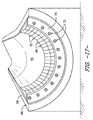
- the step of placing the plurality of root inserts 46 atop the outer layer 42 and placing the plurality of spacers 52 between one or more of the plurality of root inserts 46 may include mounting the root inserts 46 and/or the spacers 52 to the removable flange 68, which is configured to maintain the position of the root inserts 46 and/or the spacers 52 during infusing.
- the root inserts 46 and the spacers 52 may be mounted to the removable flange via one or more fasteners 70.
- the root assembly 30 may include only root inserts 46 as shown in FIG. 3 .
- the method 100 of assembling the root assembly 30 may include varying a number of the root inserts 46 and spacers 52 based on load concentrations in the root assembly 30.
- the arrangement of root inserts-to-spacers can be tailored such that the number of root inserts 46 is increased in areas of higher concentrations of load (for example, the portion of the root closest to the spar caps 20, 22).
- the number of root inserts 46 may be increased or decreased based on varying load concentrations in the root assembly 30.
- the method 100 may include placing at least one spacer 52 between each of the root inserts 46 such that the root inserts 46 are evenly spaced. Such an embodiment provides equal separation of the inserts 46 to tailor the rotor blade 16 to the minimum number of bolts required without having to over design the blade root due to standard geometry of the insert 46.
- the method 100 may include placing the spacers 52 between the root inserts 46 randomly.
- the method 100 may also include preparing one or more surfaces 45, 53 of the root inserts 46 and/or the spacers 52 (or the inner and outer sidewall surfaces 40, 42) so as to improve adhesion of the surfaces during infusion and/or to promote resin transfer during infusing.
- the step of preparing one or more surfaces may include providing a bonding agent 64 between one or more of the surfaces, grinding one or more of the surfaces, or similar.
- the method 100 may also include forming the root inserts 46 and/or the spacers 52 using any suitable manufacturing processes.
- the method 100 may include pultruding the root inserts 46 and/or the spacers 52, e.g. using thermoplastic or thermoset materials reinforced with carbon or glass fibers.
- the step of pultruding the spacers 52 may further include providing a low-density core material 58 to fill an internal volume of the spacers 52.
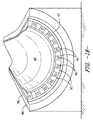
- the method 100 may also include placing an inner layer 40 of composite material into the shell mold 66 atop the root inserts 46 and the spacers 52 to form an inner sidewall surface 40 of the root assembly 30, for example, as shown in FIG. 18 .
- the method 100 may then include infusing the root inserts 46 and the spacers 52 between the inner and outer layers 40, 42, e.g. via a resin.
- the method 100 may include infusing the root inserts 46 and the spacers 52 between the inner and outer layers 40, 42 via vacuum infusion, resin transfer molding (RTM), light resin transfer molding (RTM), vacuum assisted resin transfer molding (VARTM), or similar.
- the method 100 may also include welding the thermoplastic inserts 46 between the inner and outer layers 40, 42 (rather than including or bonding the inserts 46 between the inner and outer layers 40, 42). As such, the thermoplastic inserts 46 may be reheated, removed, and replaced in the event damage and/or manufacturing defects. More specifically, in certain embodiments, the method 100 may include heating the metal bushing 48 of the inserts 46 such that the surrounding thermoplastic material is heated. Thus, the heated thermoplastic material can be welded to surrounding thermoplastic mating surfaces, e.g. the inner and outer layers 40, 42.
- pressure may also be applied from the root end of the metal bushing 48 to ensure a suitable weld bond. Accordingly, in further embodiments, a similar process may be used to remove an existing insert 46, i.e. by applying heat to the metal bushing 48 while pulling on the insert 46 to be removed.
- the process for infusing, bonding, or welding the inserts 46 between the inner and outer layers 40, 42 can then be repeated for each blade half (if necessary). Further, the blade halves (where first and second shell molds are used) are allowed to cure for a predetermined time period. Once cured, the removable flange 68 may be removed and reused to manufacture additional root assemblies 30. In addition, the blade halves (if applicable) may be bonded together, e.g. with an adhesive, to form the root assembly 30. The adhesive is then allowed to cure to a state suitable for ejecting the root assembly 30 from the shell molds. The root assembly 30 may then be ejected from the shell mold 66 and located to an area for finishing.
Landscapes
- Engineering & Computer Science (AREA)
- Mechanical Engineering (AREA)
- Chemical & Material Sciences (AREA)
- General Engineering & Computer Science (AREA)
- Composite Materials (AREA)
- Manufacturing & Machinery (AREA)
- Life Sciences & Earth Sciences (AREA)
- Sustainable Development (AREA)
- Sustainable Energy (AREA)
- Combustion & Propulsion (AREA)
- Materials Engineering (AREA)
- Wind Motors (AREA)
Description
- The present subject matter relates generally to wind turbines and, more particularly, to a rotor blade root assembly for a wind turbine.
- Wind power is considered one of the cleanest, most environmentally friendly energy sources presently available, and wind turbines have gained increased attention in this regard. A modem wind turbine typically includes a tower, a generator, a gearbox, a nacelle, and a rotor. The rotor is coupled to the nacelle and includes a rotatable hub having one or more rotor blades. The rotor blades are connected to the hub by a blade root. The rotor blades capture kinetic energy from wind using known airfoil principles and convert the kinetic energy into mechanical energy through rotational energy to turn a shaft coupling the rotor blades to a gearbox, or if a gearbox is not used, directly to the generator. The generator then converts the mechanical energy to electrical energy that may be deployed to a utility grid.
- The particular size of the rotor blades is a significant factor contributing to the overall capacity of the wind turbine. Specifically, increases in the length or span of a rotor blade may generally lead to an overall increase in the energy production of a wind turbine. Accordingly, efforts to increase the size of rotor blades aid in the continuing growth of wind turbine technology and the adoption of wind energy as an alternative and commercially competitive energy source. Such increases in rotor blade size, however, may impose increased loads on various wind turbine components. For example, larger rotor blades may experience increased stresses at the connection between the blade root and the hub, leading to challenging design constraints, both characterized by extreme events and fatigue life requirements.
- Many rotor blades utilize root bolt inserts to reduce the stresses at the blade root-hub interface. Such root bolt inserts can be produced using a variety of processes, including but not limited to pultrusions. A common approach is to infuse root bolt inserts with fabrics and rovings to provide a laminate substrate by which later infusions can be used to effectively bond the insert into the blade root laminates. Round, square, trapezoidal, or similar profiles may be used, though the number of root bolt inserts required often leaves a gap between inserts that must be filled with a mixture of glass and resin. This process entails cutting very small strips of glass and placing the strips manually in the blade root and then using a typical vacuum infusion process. Such a process can be labor-intensive and often results in poor laminate quality of the laminates between the root bolt inserts.
- Thus, there is a need for an improved rotor blade root assembly that addresses the aforementioned issues. Accordingly, a rotor blade root assembly that reduces labor cycle time and improves laminate quality would be advantageous.
- Various aspects and advantages of the invention will be set forth in part in the following description, or may be clear from the description, or may be learned through practice of the invention.
- In accordance with one embodiment of the invention, a root assembly for a rotor blade of a wind turbine is disclosed. The root assembly includes a blade root section having an inner sidewall surface and an outer sidewall surface separated by a radial gap, a plurality of root inserts spaced circumferentially within the radial gap, and a plurality of pultruded spacers configured between one or more of the root inserts. Further, each of the root inserts includes at least one bushing surrounded by a pre-cured or pre-consolidated composite material. Each of the bushings are configured to receive a root bolt. Thus, the root bolts are configured to secure the root assembly to a hub of the wind turbine. In addition, the pultruded spacers may be constructed of a pre-cured or pre-consolidated composite material.
- In one embodiment, the root assembly may further include one or more pultruded root inserts, wherein the pre-cured or pre-consolidated composite materials of the pultruded root inserts and/or the pultruded spacers may each include a plurality of fiber materials cured together via a resin. More specifically, the plurality of fiber materials may include at least one of carbon or glass fibers or rovings, or similar. In addition, the resin may include at least one of a thermoplastic material or a thermoset material. More specifically, in certain embodiments, the thermoplastic material may include at least one of polyvinyl chlorides (PVC), polyvinylidene chlorides, polyvinyl acetates, polypropylenes, polyethylenes, polystyrenes, polyurethanes, polyphenyl sulfide, polybutylene terephthalate (PBT), polyamides, polymethyl methacrylate (PMMA), glycolised polyethylene terephthalate (PET-G), polyethylene terephthalate (PET), or similar. In additional embodiments, the thermoset material may include at least one of polyester, ester, epoxy, melamine formaldehyde, urea formaldehyde, or similar.
- In further embodiments, the plurality of spacers may also include a core material. For example, in certain embodiments, the core material may include a lightweight material such as wood (e.g., balsa), foam (e.g., extruded polystyrene foam) or a combination of such materials. More specifically, the core material may include a low-density foam material.
- In certain embodiments, the root assembly may also include a bonding agent configured within the radial gap, e.g. between the surfaces of the root inserts and/or spacers, that is configured to promote surface adhesion and/or resin transfer throughout the root assembly. More specifically, in particular embodiments, the bonding agent may include chopped fiber mat (CFM), a biaxially-stretched plastic film, a three-dimensional glass fabric, or similar.
- In additional embodiments, the components of the root assembly may be joined via at least one of welding, vacuum infusion, resin transfer molding (RTM), light resin transfer molding (RTM), vacuum assisted resin transfer molding (VARTM), or similar.
- In further embodiments, the root inserts and the spacers may each include side edges such that when the root inserts and spacers are arranged in the root assembly, the side edges of the root inserts and adjacent spacers align and are substantially flush to form first and second continuous surfaces. More specifically, the plurality of root inserts may include any suitable cross-sectional shape. For example, in certain embodiments, the cross-sectional shape of the root inserts may include a square, a rectangle, or similar. In additional embodiments, the plurality of spacers may also include any suitable cross-sectional shape, for example, that corresponds to the cross-sectional shape of the plurality of root inserts.
- In another aspect, the present disclosure is directed to a method of manufacturing a root assembly for a rotor blade of a wind turbine. The method includes placing an outer layer of thermoplastic material into a shell mold of a blade root section of the rotor blade to form an outer sidewall surface of the root assembly. Another step includes placing a plurality of root inserts atop the outer layer, wherein each of the root inserts includes at least one metal bushing surrounded by a thermoplastic material. The method also includes placing an inner layer of thermoplastic material into a shell mold atop the root inserts to form an inner sidewall surface of the root assembly. A further step includes joining the root inserts between the inner and outer layers.
- In another embodiment, the step of joining the root inserts between the inner and outer layers may further include welding the root inserts between the inner and outer layers. More specifically, in certain embodiments, the step of welding the root inserts between the inner and outer layers may also include heating the metal bushings of the root inserts such that the surrounding thermoplastic material is heated and welding the heated thermoplastic material of the root inserts to the inner and outer layers.
- In yet another aspect, the present disclosure is directed to a method of manufacturing a root assembly for a rotor blade of a wind turbine. The method includes placing an outer layer of composite material into a shell mold of a blade root section of the rotor blade to form an outer sidewall surface of the root assembly. Another step includes placing a plurality of root inserts atop the outer layer, wherein each of the root inserts includes at least one metal bushing surrounded by a pre-cured or pre-consolidated composite material. The method also includes placing a plurality of spacers between one or more of the plurality of root inserts, wherein the spacers are constructed, at least in part, of a pre-cured or pre-consolidated composite material. Still a further step includes placing an inner layer of composite material into a shell mold atop the root inserts and the spacers to form an inner sidewall surface of the root assembly. Thus, the method also includes infusing the root inserts and the spacers between the inner and outer layers via a resin.
- In one embodiment, the method may also include varying a number of the root inserts based on load concentrations in the root assembly. As such, the number of root inserts may be increased or decreased based on varying load concentrations in the root assembly. In another embodiment, the method may include placing at least one spacer between each of the root inserts such that the root inserts are evenly spaced.
- In additional embodiments, the step of placing the plurality of root inserts atop the outer layer and placing the plurality of spacers between one or more of the plurality of root inserts may include mounting the plurality of root inserts and the plurality of spacers to a removable flange that is configured to maintain position of the root inserts and the spacers during infusing. Thus, after infusing, the removable flange may be removed and reused when making additional root assemblies.
- In certain embodiments, the method may also include pultruding at least one of the plurality of root inserts or the plurality of spacers, wherein the pre-cured or pre-consolidated composite materials may include a plurality of fiber materials cured together via a resin. More specifically, in particular embodiments, the plurality of fiber materials may include at least one of carbon fibers or rovings, glass fibers or rovings, or similar. Further, in particular embodiments, the step of pultruding the plurality of spacers may further include providing a low-density core material to fill an internal volume of the spacers.
- In further embodiments, the method may also include preparing one or more surfaces of the root inserts and/or the spacers so as to improve adhesion of the surfaces or to promote resin transfer during infusing. For example, in certain embodiments, the step of preparing one or more surfaces of the root inserts or the spacers may include at least one of providing a bonding agent between one or more of the surfaces, grinding one or more of the surfaces, or similar.
- In additional embodiments, the method may also include infusing the root inserts and the spacers between the inner and outer layers via at least one of vacuum infusion, resin transfer molding (RTM), light resin transfer molding (RTM), vacuum assisted resin transfer molding (VARTM), or similar.
- In yet another embodiment, the shell mold may include a first shell half and a second shell half. As such, the method may include forming a first blade section via the first shell half, forming a second blade section via the second shell half, and bonding the first and second blade sections together via an adhesive. It should be understood that each blade section may be formed via the method steps as described herein.
- These and other features, aspects and advantages of the present invention will be further supported and described with reference to the following description and appended claims. The accompanying drawings, which are incorporated in and constitute a part of this specification, illustrate embodiments of the invention and, together with the description, serve to explain the principles of the invention. In the drawings:
-
FIG. 1 illustrates a perspective view of one embodiment of a wind turbine according to the present disclosure; -
FIG. 2 illustrates a perspective view of one embodiment of a rotor blade of a wind turbine according to the present disclosure; -
FIG. 3 illustrates an enlarged view of one embodiment of an end face of a root assembly of a rotor blade according to the present invention; -
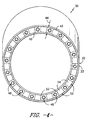
FIG. 4 illustrates an enlarged view of another embodiment of an end face of a root assembly of a rotor blade according to the present invention; -
FIG. 5 illustrates an enlarged view of yet another embodiment of an end face of a root assembly of a rotor blade according to the present invention; -
FIG. 6 illustrates a detailed view of a portion of a root assembly of a wind turbine rotor blade according to the present disclosure; -
FIG. 7 illustrates a perspective view of one embodiment of a root insert for a root assembly of a wind turbine rotor blade according to the present disclosure; -
FIG. 8 illustrates a perspective view of one embodiment of a spacer for a root assembly of a wind turbine rotor blade according to the present disclosure; -
FIG. 9 illustrates a cross-sectional view of the spacer ofFIG. 6 along line 7-7; -
FIG. 10 illustrates a perspective view of a portion of a root assembly of a wind turbine rotor blade according to the present disclosure; -
FIG. 11 illustrates an enlarged view of another embodiment of a portion of a root assembly of a wind turbine rotor blade according to the present invention; -
FIG. 12 illustrates a detailed view of a portion of a root assembly of a wind turbine rotor blade according to the present disclosure; -
FIG. 13 illustrates a perspective view of another embodiment of a root insert for a root assembly of a wind turbine rotor blade according to the present disclosure; -
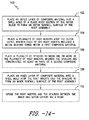
FIG. 14 illustrates a flow diagram of a method for manufacturing a root assembly for a wind turbine rotor blade according to the present disclosure; -
FIG. 15 illustrates a perspective view of a shell mold used during the manufacturing process of the root assembly of a wind turbine rotor blade according to the present disclosure, particularly illustrating the outer layer placed onto the shell mold; -
FIG. 16 illustrates a perspective view of a shell mold used during the manufacturing process of the root assembly of a wind turbine rotor blade according to the present disclosure, particularly illustrating the outer layer, the root inserts, and the spacers placed onto the shell mold; -
FIG. 17 illustrates a perspective view of a shell mold used during the manufacturing process of the root assembly of a wind turbine rotor blade according to the present disclosure, particularly illustrating the root inserts and the spacers secured in the shell mold via a removable flange; and -
FIG. 18 illustrates a perspective view of a shell mold used during the manufacturing process of the root assembly of a wind turbine rotor blade according to the present disclosure, particularly illustrating the root inserts and the spacers between the inner and outer layers of composite material before infusion. - Reference now will be made in detail to embodiments of the invention, one or more examples of which are illustrated in the drawings. Each example is provided by way of explanation of the invention, not limitation of the invention. In fact, it will be apparent to those skilled in the art that various modifications and variations can be made in the present invention without departing from the scope or spirit of the invention. For instance, features illustrated or described as part of one embodiment can be used with another embodiment to yield a still further embodiment. Thus, it is intended that the present invention covers such modifications and variations as come within the scope of the appended claims and their equivalents.
- Generally, the present disclosure is directed to a root assembly for a rotor blade of a wind turbine and methods of manufacturing same. The root assembly includes a blade root section having an inner sidewall surface and an outer sidewall surface separated by a radial gap, a plurality of root inserts spaced circumferentially within the radial gap, and optionally a plurality of spacers configured between one or more of the root inserts. Further, the blade root section may be constructed, at least in part, from a thermoplastic material or a thermoset material. In addition, each of the root inserts includes at least one bore hole surrounded by a pre-cured or pre-consolidated composite material, e.g. a thermoplastic material or a thermoset material. Moreover, the spacers may also be constructed of a pre-cured or pre-consolidated composite material, e.g. a thermoplastic material or a thermoset material. More specifically, the thermoplastic and/or thermoset materials may be reinforced with glass or carbon fibers or rovings.
- The present disclosure provides many advantages not present in the prior art. For example, the root assembly of the present disclosure provides improved laminate quality between the root inserts, e.g. due to the combination of thermoset and/or thermoplastic components. In addition, the root assembly of the present disclosure enables the use of root inserts in thermoplastic as well as thermoset rotor blades. Further, the resin consumption in the primary shell infusion process of the rotor blades may be reduced, thereby reducing overall manufacturing costs. Further, the labor required to place the root inserts and/or the spacers into the shell mold may be reduced as compared to using dry fabrics to fill the volume. Moreover, the pultruded root inserts allows significant reductions in manufacturing cycle time as compared to using T-bolt and/or barrel nut configurations.
- Referring now to the drawings,
FIG. 1 illustrates a perspective view of a horizontalaxis wind turbine 10. It should be appreciated that thewind turbine 10 may also be a vertical-axis wind turbine. As shown in the illustrated embodiment, thewind turbine 10 includes atower 12, anacelle 14 mounted on thetower 12, and arotor hub 18 that is coupled to thenacelle 14. Thetower 12 may be fabricated from tubular steel or other suitable material. Therotor hub 18 includes one ormore rotor blades 16 coupled to and extending radially outward from thehub 18. As shown, therotor hub 18 includes threerotor blades 16. However, in an alternative embodiment, therotor hub 18 may include more or less than threerotor blades 16. Therotor blades 16 rotate therotor hub 18 to enable kinetic energy to be transferred from the wind into usable mechanical energy, and subsequently, electrical energy. Specifically, thehub 18 may be rotatably coupled to an electric generator (not illustrated) positioned within thenacelle 14 for production of electrical energy. - Referring to
FIG. 2 , one of therotor blades 16 ofFIG. 1 is illustrated in accordance with aspects of the present subject matter. As shown, therotor blade 16 generally includes aroot assembly 30 having ablade root section 32 that is configured to be mounted or otherwise secured to the hub 18 (FIG. 1 ) of thewind turbine 10. In addition, ablade tip section 34 is disposed opposite theblade root section 32. Abody shell 21 of the rotor blade generally extends between theblade root section 32 and theblade tip section 34 along alongitudinal axis 24. Thebody shell 21 may generally serve as the outer casing/covering of therotor blade 16 and may define a substantially aerodynamic profile, such as by defining a symmetrical or cambered airfoil-shaped cross-section. Thebody shell 21 may also define apressure side 36 and asuction side 38 extending between leading and trailing ends 26, 28 of therotor blade 16. Further, therotor blade 16 may also have aspan 23 defining the total length between theblade root section 32 and theblade tip section 34 and achord 25 defining the total length between theleading edge 26 and the trailingedge 28. As is generally understood, thechord 25 may generally vary in length with respect to thespan 23 as therotor blade 16 extends from theblade root section 32 to theblade tip section 34. - In several embodiments, the
body shell 21 of therotor blade 16 may be formed as a single, unitary component. Alternatively, thebody shell 21 may be formed from a plurality of shell components or segments. Additionally, thebody shell 21 may generally be formed from any suitable material. For instance, in one embodiment, thebody shell 21 may be formed entirely from a laminate composite material, such as a carbon fiber reinforced laminate composite or a glass fiber reinforced laminate composite. Alternatively, one or more portions of thebody shell 21 may be configured as a layered construction and may include a core material, formed from a lightweight material such as wood (e.g., balsa), foam (e.g., extruded polystyrene foam) or a combination of such materials, disposed between layers of laminate composite material. - The
rotor blade 16 may also include one or more longitudinally extending structural components configured to provide increased stiffness, buckling resistance and/or strength to therotor blade 16. For example, therotor blade 16 may include a pair of longitudinally extending spar caps 20, 22 configured to be engaged against the opposing inner surfaces of the pressure andsuction sides rotor blade 16, respectively. Additionally, one or more shear webs (not shown) may be disposed between the spar caps 20, 22 so as to form a beam-like configuration. The spar caps 20, 22 may generally be designed to control the bending stresses and/or other loads acting on therotor blade 16 in a generally span-wise direction (a direction parallel to thespan 23 of the rotor blade 16) during operation of awind turbine 10. Similarly, the spar caps 20, 22 may also be designed to withstand the span-wise compression occurring during operation of thewind turbine 10. - Referring now to
FIGS. 3-13 various views and/or components of multiple embodiments of theroot assembly 30 according to the present disclosure are illustrated. More specifically, as shown, theroot assembly 30 includes ablade root section 32 having anend face 33 with a substantially annular cross-section defined by aninner sidewall surface 40 and anouter sidewall surface 42. Further, as shown generally in the figures, the inner and outer sidewall surfaces 40, 42 are separated by aradial gap 44. In addition, in certain embodiments, theblade root section 32 may be constructed of a first composite material. For example, in certain embodiments, the first composite material may include a thermoplastic material or a thermoset material. In addition, the thermoset or thermoplastic materials of theblade root section 32 may be reinforced with one or more fibers, including but not limited to glass or carbon fibers or rovings. - In addition, as shown, the
root assembly 30 also includes a plurality of root inserts 46 spaced circumferentially within theradial gap 44 and optionally a plurality of spacers 52 (FIGS. 4-6 and8-13 ) configured between one or more of the root inserts 46. Moreover, each of the root inserts 46 includes at least one bore hole orbushing 48 surrounded by a secondcomposite material 50. For example, as shown inFIGS. 3 and4 , each of the root inserts 46 includes asingle bushing 48 surrounded by the secondcomposite material 50. Alternatively, as shown inFIG. 5 , one or more of the root inserts 46 may include a plurality ofbushings 48 surrounded by a secondcomposite material 50. More specifically, in certain embodiments, the bushing(s) 48 may include a metal bushing cured within and surrounded by the secondcomposite material 50. For example, in certain embodiments, the second composite material (like the first composite material) may include a thermoplastic material or a thermoset material. In addition, as mentioned, the thermoset or thermoplastic materials may be reinforced with one or more fibers, including but not limited to glass or carbon fibers or rovings. - More specifically, in certain embodiments, the second composite material may be different than the first composite material. For example, the first composite material may be a thermoset material, whereas the second composite material may be a thermoplastic material. In alternative embodiments, the first composite material may be a thermoplastic material, whereas the second composite material may be a thermoset material. In still additional embodiments, both the first and second composite materials may be thermoplastic materials. In addition, the
spacers 52 as described herein may be constructed, at least in part, of a pre-consolidated or pre-curedcomposite material 54, e.g. a thermoplastic material or a thermoset material. - The thermoplastic materials as described herein generally encompass a plastic material or polymer that is reversible in nature. For example, thermoplastic materials typically become pliable or moldable when heated to a certain temperature and solidify upon cooling. Further, thermoplastic materials may include amorphous thermoplastic materials and semi-crystalline thermoplastic materials. For example, some amorphous thermoplastic materials may generally include, but are not limited to styrenes, vinyls, cellulosics, polyesters, acrylics, polysulphones, and/or imides. More specifically, example amorphous thermoplastic materials may include polystyrene, acrylonitrile butadiene styrene (ABS), polymethyl methacrylate (PMMA), glycolised polyethylene terephthalate (PET-G), polycarbonate, polyvinyl acetate, amorphous polyamide, polyvinyl chlorides (PVC), polyvinylidene chloride, polyurethane, or similar. In addition, example semi-crystalline thermoplastic materials may generally include, but are not limited to polyolefins, polyamides, fluropolymer, ethyl-methyl acrylate, polyesters, polycarbonates, and/or acetals. More specifically, example semi-crystalline thermoplastic materials may include polybutylene terephthalate (PBT), polyethylene terephthalate (PET), polypropylene, polyphenyl sulfide, polyethylene, polyamide (nylon), polyetherketone, or similar. Further, the thermoset materials as described herein generally encompass a plastic material or polymer that is non-reversible in nature. For example, thermoset materials, once cured, cannot be easily remolded or returned to a liquid state. As such, after initial forming, thermoset materials are generally resistant to heat, corrosion, and/or creep. Example thermoset materials may generally include, but are not limited to, some polyesters, some polyurethanes, esters, epoxies, melamine formaldehyde, urea formaldehyde, or similar.
- In addition, in certain embodiments, the root inserts 46 and/or the
spacers 52 may be pultruded from one or more composite materials, respectively. As used herein, the terms "pultruded," "pultrusions," or similar generally encompass reinforced materials (e.g. fibers or woven or braided strands) that are impregnated with a resin and pulled through a stationary die such that the resin cures or undergoes polymerization. As such, the process of manufacturing pultruded members is typically characterized by a continuous process of composite materials that produces composite parts having a constant cross-section. Thus, the composite materials may include pultrusions constructed of glass or carbon reinforced thermoset or thermoplastic materials. Further, the root inserts 46 and/or thespacers 52 may be formed of the same composite materials or different composite materials. In addition, the pultruded components may be produced from rovings, which generally encompass long and narrow bundles of fibers that are not combined until joined by a cured resin. - In particular embodiments, as shown in
FIGS. 8 and 9 , thespacers 52 may also include acore material 58. For example, in certain embodiments, thecore material 58 may include a lightweight material such as wood (e.g., balsa), foam (e.g., extruded polystyrene foam) or a combination of such materials. More specifically, thecore material 58 may include a low-density foam material. As such, thecore material 58 is configured to occupy space that would otherwise fill with fiber material and/or resin during the pultrusion process. Thus, in certain embodiments, thecore material 58 may be configured to fill enough space in the pultrusion spacer to allow sufficient curing throughout thespacer 52. - Referring particularly to
FIGS. 6-10 , the root inserts 46 and/or thespacers 52 may each include side edges 45, 53, respectively, such that when the root inserts 46 and thespacers 52 are arranged in the root assembly 30 (FIGS. 6 and10 ), the side edges 45, 53 substantially align and are flush to form first and secondcontinuous surfaces 55, 56. More specifically, the plurality of root inserts 46 may include any suitablecross-sectional shape 60. For example, as shown inFIGS. 5-8 , thecross-sectional shape 60 of the root inserts 46 may be a square, a rectangle, a circle, or similar. More specifically, as shown inFIGS. 4-10 , thecross-sectional shape 60 of the root inserts 46 are substantially square. Alternatively, as shown inFIGS. 11-13 , thecross-sectional shape 60 of the root inserts 46 is substantially circular. In additional embodiments, the plurality ofspacers 52 may also include any suitablecross-sectional shape 62. For example, as shown inFIGS. 4-10 , thecross-sectional shape 62 of the spacers may correspond to thecross-sectional shape 60 of the plurality of root inserts 46 such that the inserts and spacers may be aligned together in theradial gap 44. In addition, the root inserts 46 andspacers 52 may be sized so as to follow the curvature of theradial gap 44. Alternatively, as shown inFIGS. 11-13 , thecross-sectional shape 62 of thespacers 52 may include a generally hour glass shape that corresponds to the circularcross-sectional shape 60 of the root inserts 46. For example, as shown in the illustrated embodiment, the side edges 53 of thespacers 52 may be concave such that the edges receive the root inserts 46 therein. - In additional embodiments, as shown in
FIG. 6 , theroot assembly 30 may also include abonding agent 64 configured within theradial gap 44, e.g. between the various surfaces between the root inserts 46 and/orspacers 52. Thus, thebonding agent 64 is configured to promote surface adhesion and/or resin transfer throughout theroot assembly 30 during the manufacturing process. More specifically, in particular embodiments, thebonding agent 64 may include chopped fiber mat (CFM), a biaxially-stretched plastic film, a three-dimensional glass fabric, or similar. Thus, in additional embodiments, theroot assembly 30 may be formed via at least one of vacuum infusion, resin transfer molding (RTM), light resin transfer molding (RTM), vacuum assisted resin transfer molding (VARTM), or similar, which is discussed in more detail below. - Referring now to
FIG. 14 , a flow diagram of one embodiment of amethod 100 of manufacturing aroot assembly 30 for arotor blade 16 of awind turbine 10 is illustrated. As shown at 102, themethod 100 includes placing anouter layer 42 of composite material into ashell mold 66 of ablade root section 32 of therotor blade 16 to form anouter sidewall surface 42 of theroot assembly 30, for example, as shown inFIG. 15 . More specifically, theouter layer 42 of composite material may include a thermoplastic material skin that may optionally be reinforced with glass or carbon fibers. Thus, themethod 100 may including laying down one or more plies (e.g. glass or carbon fibers) in theshell mold 66 that extend from theend face 33 of theblade root section 32 toward theblade tip section 34. In addition, the plies are typically laid up in the mold so as to extend from the leadingedge 26 to the trailingedge 28 of therotor blade 16. The plies may then be infused together, e.g. via a thermoplastic material. Further, as shown, theshell mold 66 may include afirst shell half 68 and a second shell half (not shown). As such, themethod 100 may include forming a first blade section via thefirst shell half 68, forming a second blade section via the second shell half, and bonding the first and second blade sections together, e.g. via an adhesive. It should be understood that each blade section may be formed via the method steps as described herein. - Thus, as shown at 104, the
method 100 may also include placing a plurality of root inserts 46 atop theouter layer 42, for example, as shown inFIG. 16 . In particular embodiments, as shown inFIG. 17 , eachroot insert 46 may be placed in the mold and then bolted to aremovable flange 68 which can be removed at a later time. As mentioned, the root inserts 46 may be constructed of a thermoplastic or a thermoset material. In addition, as shown at 106, themethod 100 may optionally include placing a plurality ofspacers 52 between one or more of the plurality of root inserts 46, for example, as shown inFIG. 16 . It should be understood that thespacers 52 may be placed into the shell mold simultaneously with the root inserts 46, e.g. by alternatively placing aspacer 52, then aninsert 46, and so on. For example, in certain embodiments, themethod 100 may include placing at least onespacer 52 adjacent to an installedinsert 46 and then subsequently placing anotherinsert 52 on the other side of the installedinsert 46 and bolting thespacers 52 to theremovable flange 68. In other words, the step of placing the plurality of root inserts 46 atop theouter layer 42 and placing the plurality ofspacers 52 between one or more of the plurality of root inserts 46 may include mounting the root inserts 46 and/or thespacers 52 to theremovable flange 68, which is configured to maintain the position of the root inserts 46 and/or thespacers 52 during infusing. For example, as shown, the root inserts 46 and thespacers 52 may be mounted to the removable flange via one ormore fasteners 70. - It should also be understood that any arrangement of root inserts-to-spacers may be used in the
root assembly 30. For example, in certain embodiments, theroot assembly 30 may include only root inserts 46 as shown inFIG. 3 . Alternatively, themethod 100 of assembling theroot assembly 30 may include varying a number of the root inserts 46 andspacers 52 based on load concentrations in theroot assembly 30. More specifically, the arrangement of root inserts-to-spacers can be tailored such that the number of root inserts 46 is increased in areas of higher concentrations of load (for example, the portion of the root closest to the spar caps 20, 22). As such, in certain embodiments, the number of root inserts 46 may be increased or decreased based on varying load concentrations in theroot assembly 30. In a further embodiment, as shown inFIGS. 4 ,11 , and16 , themethod 100 may include placing at least onespacer 52 between each of the root inserts 46 such that the root inserts 46 are evenly spaced. Such an embodiment provides equal separation of theinserts 46 to tailor therotor blade 16 to the minimum number of bolts required without having to over design the blade root due to standard geometry of theinsert 46. Alternatively, as shown inFIG. 5 , themethod 100 may include placing thespacers 52 between the root inserts 46 randomly. - In further embodiments, the
method 100 may also include preparing one ormore surfaces bonding agent 64 between one or more of the surfaces, grinding one or more of the surfaces, or similar. - In addition, as mentioned, the
method 100 may also include forming the root inserts 46 and/or thespacers 52 using any suitable manufacturing processes. For example, in certain embodiments, themethod 100 may include pultruding the root inserts 46 and/or thespacers 52, e.g. using thermoplastic or thermoset materials reinforced with carbon or glass fibers. More specifically, in particular embodiments, the step of pultruding thespacers 52 may further include providing a low-density core material 58 to fill an internal volume of thespacers 52. - Referring still to
FIG. 14 , as shown at 108, themethod 100 may also include placing aninner layer 40 of composite material into theshell mold 66 atop the root inserts 46 and thespacers 52 to form aninner sidewall surface 40 of theroot assembly 30, for example, as shown inFIG. 18 . Thus, as shown at 110, themethod 100 may then include infusing the root inserts 46 and thespacers 52 between the inner andouter layers method 100 may include infusing the root inserts 46 and thespacers 52 between the inner andouter layers - In alternative embodiments, where the inner and
outer layers method 100 may also include welding the thermoplastic inserts 46 between the inner andouter layers 40, 42 (rather than including or bonding theinserts 46 between the inner andouter layers 40, 42). As such, the thermoplastic inserts 46 may be reheated, removed, and replaced in the event damage and/or manufacturing defects. More specifically, in certain embodiments, themethod 100 may include heating themetal bushing 48 of theinserts 46 such that the surrounding thermoplastic material is heated. Thus, the heated thermoplastic material can be welded to surrounding thermoplastic mating surfaces, e.g. the inner andouter layers metal bushing 48 to ensure a suitable weld bond. Accordingly, in further embodiments, a similar process may be used to remove an existinginsert 46, i.e. by applying heat to themetal bushing 48 while pulling on theinsert 46 to be removed. - The process for infusing, bonding, or welding the
inserts 46 between the inner andouter layers removable flange 68 may be removed and reused to manufactureadditional root assemblies 30. In addition, the blade halves (if applicable) may be bonded together, e.g. with an adhesive, to form theroot assembly 30. The adhesive is then allowed to cure to a state suitable for ejecting theroot assembly 30 from the shell molds. Theroot assembly 30 may then be ejected from theshell mold 66 and located to an area for finishing. - This written description uses examples to disclose the invention, including the preferred mode, and also to enable any person skilled in the art to practice the invention, including making and using any devices or systems and performing any incorporated methods. The patentable scope of the invention is defined by the claims, and may include other examples that occur to those skilled in the art. Such other examples are intended to be within the scope of the claims if they include structural elements that do not differ from the literal language of the claims, or if they include equivalent structural elements with insubstantial differences from the literal languages of the claims.
- Various aspects and embodiments of the present invention are defined by the following numbered clauses:
- 1. A root assembly for a rotor blade of a wind turbine, comprising:
- a blade root section comprising an inner sidewall surface and an outer sidewall surface separated by a radial gap;
- a plurality of root inserts spaced circumferentially within the radial gap, each of the root inserts comprising at least one bushing surrounded by a pre-consolidated composite material, each of the bushings configured to receive a root bolt, the root bolts configured to secure the root assembly to a hub of the wind turbine; and,
- a plurality of pultruded spacers configured between one or more of the root inserts, each of the pultruded spacers being constructed of a pre-consolidated composite material.
- 2. The root assembly of clause 1, further comprising pultruded root inserts, wherein the pre-consolidated composite materials of the pultruded root inserts and the pultruded spacers comprise a plurality of fiber materials cured together via a resin, wherein the plurality of fiber materials comprise at least one of carbon fibers, carbon rovings, glass fibers, or glass rovings.
- 3. The root assembly of any preceding clause, wherein the resin comprises at least one of a thermoplastic material or a thermoset material.
- 4. The root assembly of any preceding clause, wherein the plurality of spacers further comprises a low-density core material.
- 5. The root assembly of any preceding clause, further comprising a bonding agent configured within the radial gap, the bonding agent being configured to promote resin transfer during manufacturing of the root assembly.
- 6. The root assembly of any preceding clause, wherein the bonding agent comprises chopped fiber mat (CFM), a biaxially-stretched plastic film, or a three-dimensional glass fabric.
- 7. The root assembly of any preceding clause, wherein the root assembly is formed via at least one of welding, vacuum infusion, resin transfer molding (RTM), light resin transfer molding (RTM), or vacuum assisted resin transfer molding (VARTM).
- 8. The root assembly of any preceding clause, wherein the root inserts and the spacers comprises side edges such that when the root inserts and spacers are arranged in the root assembly, the side edges align and are substantially flush to form first and second continuous surfaces.
- 9. The root assembly of any preceding clause, wherein the plurality of root inserts and the plurality of spacers comprise corresponding cross-sectional shapes, the corresponding cross-sectional shapes comprising one of a square or a rectangle.
- 10. A method of manufacturing a root assembly for a rotor blade of a wind turbine, the method comprising:
- placing an outer layer of thermoplastic material into a shell mold of a blade root section of the rotor blade to form an outer sidewall surface of the root assembly;
- placing a plurality of root inserts atop the outer layer, wherein each of the root inserts includes at least one metal bushing surrounded by a thermoplastic material;
- placing an inner layer of thermoplastic material into a shell mold atop the root inserts to form an inner sidewall surface of the root assembly; and,
- joining the root inserts between the inner and outer layers.
- 11. The method of any preceding clause, wherein the step of joining the root inserts between the inner and outer layers further comprises welding the root inserts between the inner and outer layers.
- 12. The method of any preceding clause, wherein welding the root inserts between the inner and outer layers further comprises heating the metal bushings of the root inserts such that the surrounding thermoplastic material is heated and welding the heated thermoplastic material of the root inserts to the inner and outer layers.
- 13. A method of manufacturing a root assembly for a rotor blade of a wind turbine, the method comprising:
- placing an outer layer of composite material into a shell mold of a blade root section of the rotor blade to form an outer sidewall surface of the root assembly;
- placing a plurality of pultruded root inserts atop the outer layer, wherein each of the pultruded root inserts includes at least one bushing surrounded by a pre-consolidated composite material;
- placing a plurality of spacers between one or more of the plurality of root inserts, wherein the spacers are constructed, at least in part, of a pre-consolidated composite material;
- placing an inner layer of composite material into a shell mold atop the root inserts and the spacers to form an inner sidewall surface of the root assembly; and,
- infusing the root inserts and the spacers between the inner and outer layers via a resin.
- 14. The method of any preceding clause, further comprising varying a number of the root inserts based on load concentrations in the root assembly.
- 15. The method of any preceding clause, further comprising placing at least one spacer between each of the root inserts such that each of the root inserts are evenly spaced.
- 16. The method of any preceding clause, wherein placing the plurality of root inserts atop the outer layer and placing the plurality of spacers between one or more of the plurality of root inserts further comprises mounting the plurality of root inserts and the plurality of spacers to a removable flange, the removable flange configured to maintain position of the root inserts and the spacers during infusing.
- 17. The method of any preceding clause, further comprising pultruding the plurality of spacers, wherein the pre-consolidated composite materials comprise at least one of a thermoplastic material or a thermoset material.
- 18. The method of any preceding clause, wherein pultruding the plurality of spacers further comprises providing a low-density core material to fill an internal volume of the spacers.
- 19. The method of any preceding clause, further comprising preparing one or more surfaces of the root inserts or the spacers to improve adhesion of the surfaces or to promote resin transfer during infusing, wherein preparing the one or more surfaces of the root inserts or the spacers further comprises at least one of providing a bonding agent between one or more of the surfaces or grinding one or more of the surfaces.
- 20. The method of any preceding clause, further comprising infusing the root inserts and the spacers between the inner and outer layers via at least one of vacuum infusion, resin transfer molding (RTM), light resin transfer molding (RTM), or vacuum assisted resin transfer molding (VARTM).
Claims (15)
- A root assembly (30) for a rotor blade (16) of a wind turbine (10), comprising:a blade root section (32) comprising an inner sidewall surface (40) and an outer sidewall surface (42) separated by a radial gap (44);a plurality of root inserts (46) spaced circumferentially within the radial gap (44), each of the root inserts (46) comprising at least one bushing (48) surrounded by a pre-consolidated composite material (50), each of the bushings (48) configured to receive a root bolt, the root bolts configured to secure the root assembly (30) to a hub (18) of the wind turbine (10); and,a plurality of pultruded spacers (52) configured between one or more of the root inserts (46), each of the pultruded spacers (52) being constructed of a pre-consolidated composite material (50).
- The root assembly (30) of claim 1, further comprising pultruded root inserts (46), wherein the pre-consolidated composite materials (50) of the pultruded root inserts (46) and the pultruded spacers (52) comprise a plurality of fiber materials cured together via a resin, wherein the plurality of fiber materials comprise at least one of carbon fibers, carbon rovings, glass fibers, or glass rovings.
- The root assembly (30) of any preceding claim, wherein the resin comprises at least one of a thermoplastic material or a thermoset material.
- The root assembly (30) of any preceding claim, wherein the plurality of spacers (52) further comprises a low-density core material.
- The root assembly (30) of any preceding claim, further comprising a bonding agent configured within the radial gap (44), the bonding agent being configured to promote resin transfer during manufacturing of the root assembly (30), wherein the bonding agent comprises chopped fiber mat (CFM), a biaxially-stretched plastic film, or a three-dimensional glass fabric.
- The root assembly (30) of any preceding claim, wherein the root inserts (46) and the spacers (52) comprises side edges (45) such that when the root inserts (46) and spacers (52) are arranged in the root assembly (30), the side edges (45) align and are substantially flush to form first and second continuous surfaces (55, 56).
- The root assembly (30) of any preceding claim, wherein the plurality of root inserts (46) and the plurality of spacers (52) comprise corresponding cross-sectional shapes (60, 62), the corresponding cross-sectional shapes (60, 62) comprising one of a square or a rectangle.
- A method of manufacturing a root assembly (30) for a rotor blade (16) of a wind turbine (10), the method comprising:placing an outer layer (42) of thermoplastic material into a shell mold (66) of a blade root section (32) of the rotor blade (16) to form an outer sidewall surface (42) of the root assembly (30);placing a plurality of root inserts (46) atop the outer layer (42), wherein each of the root inserts (46) includes at least one metal bushing (48) surrounded by a thermoplastic material;placing an inner layer (40) of thermoplastic material into a shell mold (66) atop the root inserts (46) to form an inner sidewall surface (40) of the root assembly (30); and,joining the root inserts (46) between the inner and outer layers (40, 42).
- The method of claim 8, wherein the step of joining the root inserts (46) between the inner and outer layers (40, 42) further comprises welding the root inserts (46) between the inner and outer layers (40, 42).
- The method of claim 9, wherein welding the root inserts (46) between the inner and outer layers (40, 42) further comprises heating the metal bushings (48) of the root inserts (46) such that the surrounding thermoplastic material is heated and welding the heated thermoplastic material of the root inserts (46) to the inner and outer layers (40, 42).
- A method of manufacturing a root assembly (30) for a rotor blade (16) of a wind turbine (10), the method comprising:placing an outer layer (42) of composite material (50) into a shell mold (66) of a blade root section (32) of the rotor blade (16) to form an outer sidewall surface (42) of the root assembly (30);placing a plurality of pultruded root inserts (46) atop the outer layer (42), wherein each of the pultruded root inserts (46) includes at least one bushing (48) surrounded by a pre-consolidated composite material (50);placing a plurality of spacers (52) between one or more of the plurality of root inserts (46), wherein the spacers (52) are constructed, at least in part, of a pre-consolidated composite material (54);placing an inner layer (40) of composite material (50) into a shell mold (60) atop the root inserts (46) and the spacers (52) to form an inner sidewall surface (40) of the root assembly (30); and,infusing the root inserts (46) and the spacers (52) between the inner and outer layers (40, 42) via a resin.
- The method of claim 11, further comprising varying a number of the root inserts (46) based on load concentrations in the root assembly (30).
- The method of claim 11 or claim 12, further comprising placing at least one spacer between each of the root inserts (46) such that each of the root inserts (46) are evenly spaced.
- The method of any of claims 11 to 13, further comprising providing a low-density core material to fill an internal volume of the spacers (52).
- The method of any of claims 11 to 14, further comprising preparing one or more surfaces of the root inserts (46) or the spacers (52) to improve adhesion of the surfaces or to promote resin transfer during infusing, wherein preparing the one or more surfaces of the root inserts (46) or the spacers (52) further comprises at least one of providing a bonding agent between one or more of the surfaces or grinding one or more of the surfaces.
Applications Claiming Priority (1)
| Application Number | Priority Date | Filing Date | Title |
|---|---|---|---|
| US14/805,842 US9970304B2 (en) | 2015-07-22 | 2015-07-22 | Rotor blade root assembly for a wind turbine |
Publications (2)
| Publication Number | Publication Date |
|---|---|
| EP3121441A1 true EP3121441A1 (en) | 2017-01-25 |
| EP3121441B1 EP3121441B1 (en) | 2018-07-04 |
Family
ID=56413581
Family Applications (1)
| Application Number | Title | Priority Date | Filing Date |
|---|---|---|---|
| EP16179721.2A Active EP3121441B1 (en) | 2015-07-22 | 2016-07-15 | Rotor blade root assembly for a wind turbine |
Country Status (6)
| Country | Link |
|---|---|
| US (1) | US9970304B2 (en) |
| EP (1) | EP3121441B1 (en) |
| CN (1) | CN106368894B (en) |
| BR (1) | BR102016016867B1 (en) |
| DK (1) | DK3121441T3 (en) |
| ES (1) | ES2681876T3 (en) |
Cited By (15)
| Publication number | Priority date | Publication date | Assignee | Title |
|---|---|---|---|---|
| EP3441567A1 (en) * | 2017-08-08 | 2019-02-13 | DFS Composites Limited | Method of manufacturing a wind turbine blade root prefab, and a wind turbine blade root prefab |
| WO2019077022A1 (en) | 2017-10-18 | 2019-04-25 | Lm Wind Power International Technology Ii Aps | A wind turbine blade comprising a root end structure with a pultruded element having a transition portion |
| WO2019077027A1 (en) * | 2017-10-18 | 2019-04-25 | Lm Wind Power International Technology Ii Aps | A wind turbine blade comprising a root end structure with an adaptive positioning of the pultruded element |
| WO2019110069A1 (en) * | 2017-12-08 | 2019-06-13 | Vestas Wind Systems A/S | A replacement insert for repair of a joint connecting a wind turbine rotor blade to a rotor hub |
| GB2569294A (en) * | 2017-12-08 | 2019-06-19 | Vestas Wind Sys As | Method of repairing a joint connecting a wind turbine rotor blade to a rotor hub |
| GB2569296A (en) * | 2017-12-08 | 2019-06-19 | Vestas Wind Sys As | Method of repairing a joint connecting a wind turbine rotor blade to a rotor hub |
| GB2569297A (en) * | 2017-12-08 | 2019-06-19 | Vestas Wind Sys As | Wind turbine blade root bushing replacement method and insert |
| WO2019178476A1 (en) * | 2018-03-16 | 2019-09-19 | General Electric Company | Method for manufacturing a wind turbine rotor blade root assembly |
| EP3564523A1 (en) * | 2018-05-03 | 2019-11-06 | Nordex Energy GmbH | Flange fitting for a wind energy assembly rotor blade, reinforcement layer for a flange fitting, flange inserter, wind energy assembly rotor blade, wind turbine and method for producing a flange fitting |
| WO2021104586A1 (en) * | 2019-11-29 | 2021-06-03 | Vestas Wind Systems A/S | Improvements relating to wind turbine blade manufacture |
| EP3995688A1 (en) * | 2020-11-05 | 2022-05-11 | Nordex Blade Technology Centre APS | A method of manufacturing a wind turbine rotor blade connection part having a joining surface |
| RU2776048C2 (en) * | 2017-10-18 | 2022-07-12 | Лм Уинд Пауэр Интернешнал Текнолоджи Ii Апс | Blade of wind power plant, containing structural element of tail end with pultrusion element having transition section |
| EP4039436A1 (en) | 2021-02-03 | 2022-08-10 | Nordex Blade Technology Centre APS | A method of manufacturing a wind turbine rotor blade element with a metal insert |
| EP4239186A1 (en) * | 2022-03-02 | 2023-09-06 | LM Wind Power A/S | Fastener assembly, wind turbine hub assembly and related methods |
| EP4316785A1 (en) | 2022-08-02 | 2024-02-07 | Nordex Energy SE & Co. KG | Method for removing a metal insert |
Families Citing this family (22)
| Publication number | Priority date | Publication date | Assignee | Title |
|---|---|---|---|---|
| WO2018184642A1 (en) * | 2017-04-06 | 2018-10-11 | Vestas Wind Systems A/S | Method of retrofitting a wind turbine with an energy generating unit |
| CA3066694A1 (en) * | 2017-06-30 | 2019-01-03 | Vestas Wind Systems A/S | Improved electro-thermal heating elements |
| US11408392B2 (en) * | 2017-12-08 | 2022-08-09 | Vestas Wind Systems A/S | Insert and blank for a wind turbine blade root |
| WO2019110070A1 (en) * | 2017-12-08 | 2019-06-13 | Vestas Wind Systems A/S | Insert for a wind turbine blade root |
| JP7321166B2 (en) * | 2018-03-02 | 2023-08-04 | ダウ グローバル テクノロジーズ エルエルシー | Method for molding tubular composite structures |
| EP3557043A1 (en) * | 2018-04-20 | 2019-10-23 | youWINenergy GmbH | Blade segment for a rotor blade of a wind turbine installation and method to manufacture a blade segment |
| CN112105814B (en) * | 2018-05-04 | 2023-09-22 | 通用电气公司 | Method of forming wind turbine rotor blade roots |
| FR3087699B1 (en) * | 2018-10-30 | 2021-11-26 | Safran Aircraft Engines | HYBRIDIZATION OF THE FIBERS OF THE FIBER REINFORCEMENT OF A DAWN |
| WO2020122870A1 (en) * | 2018-12-11 | 2020-06-18 | General Electric Company | Method for manufacturing a structural component of a blade segment for a rotor blade of a wind turbine |
| DE102018133508A1 (en) * | 2018-12-21 | 2020-06-25 | Wobben Properties Gmbh | Rotor blade shape for the manufacture of a rotor blade and method |
| DE102019000056A1 (en) | 2019-01-08 | 2020-07-09 | Senvion Gmbh | Wind power plant with fastening elements for a rotor blade and a method for producing a wind power plant |
| EP3938899A4 (en) | 2019-03-11 | 2022-04-27 | Saferide Technologies Ltd. | CONTROLLER AREA NETWORK (CAN) MESSAGES COMPRESSION SYSTEM AND METHOD |
| EP3822065B1 (en) * | 2019-11-14 | 2024-07-31 | Siemens Gamesa Renewable Energy A/S | Method for manufacturing root segment sections for a root segment of a turbine blade, method for manufacturing the root segment and method for manufacturing the turbine blade |
| CN111188727B (en) * | 2020-01-13 | 2021-09-24 | 上海电气风电集团股份有限公司 | Wind turbine blade root structure and production method thereof |
| TR202011794A2 (en) | 2020-07-24 | 2020-10-21 | Megabiz Petrokimya Ueruenleri Sanayi Ve Ticaret Anonim Sirketi | TRIPLE BLADE AND REVERSE TURBINE |
| MX2023000890A (en) * | 2020-07-28 | 2023-02-22 | Envision Energy Co Ltd | MAIN BEAM FOR USE IN WIND TURBINE BLADES AND MANUFACTURING METHOD THEREOF. |
| GB202017398D0 (en) * | 2020-11-03 | 2020-12-16 | Blade Dynamics Ltd | Hybrid pultrusion plates for a spar cap of a wind turbine blade |
| CN114729621B (en) * | 2021-10-05 | 2025-08-29 | 远景能源技术私人有限公司 | A root bushing, a bushing insert thereof, a wind turbine blade including the root bushing and a manufacturing method thereof |
| EP4212324B1 (en) * | 2022-01-17 | 2024-07-17 | LM Wind Power A/S | Manufacturing of wind turbine blade spar cap |
| EP4234919A1 (en) * | 2022-02-24 | 2023-08-30 | Siemens Gamesa Renewable Energy Innovation & Technology S.L. | Root section, wind turbine blade and methods for producing and modifying a root portion of a wind turbine blade |
| EP4382285A1 (en) * | 2022-12-05 | 2024-06-12 | Nordex Blade Technology Centre APS | A method of manufacturing a wind turbine rotor blade part having an embedded placeholder |
| EP4656362A1 (en) * | 2024-05-30 | 2025-12-03 | Soluciones Solurban S.L. | Thermoplastic hybrid profile reinforced with fiberglass and carbon fiber |
Citations (5)
| Publication number | Priority date | Publication date | Assignee | Title |
|---|---|---|---|---|
| US20110044817A1 (en) * | 2008-04-29 | 2011-02-24 | Urs Bendel | Method for Establishing A Blade Connection of a Rotor Blade, A Blade Connection and a Securing Element for a Blade Connection |
| WO2012140039A2 (en) * | 2011-04-11 | 2012-10-18 | Lm Wind Power A/S | Wind turbine blade comprising circumferential retaining means in root regions |
| WO2012140048A2 (en) * | 2011-04-11 | 2012-10-18 | Lm Wind Power A/S | Wind turbine blade having a root region with elongated fastening members provided with metal fibres |
| WO2014191046A1 (en) * | 2013-05-31 | 2014-12-04 | Lm Wp Patent Holding A/S | System and method for assisting in the manufacture of a wind turbine blade shell |
| CN103061995B (en) * | 2013-01-22 | 2015-06-03 | 重庆通用工业(集团)有限责任公司 | Embedded process method for blade root screw of megawatt wind power blade |
Family Cites Families (87)
| Publication number | Priority date | Publication date | Assignee | Title |
|---|---|---|---|---|
| US4360288A (en) | 1979-09-17 | 1982-11-23 | Fiberflex Products, Inc. | Fiberglass sucker rod construction |
| US4420354A (en) | 1982-06-14 | 1983-12-13 | Gougeon Brothers, Inc. | Process for securing projecting studs in the ends of wood resin composite bodies and the like and the structure formed thereby |
| US4834616A (en) | 1986-05-30 | 1989-05-30 | Sundstrand Corporation | Means and method for securing a composite rotor blade |
| US4915590A (en) | 1987-08-24 | 1990-04-10 | Fayette Manufacturing Corporation | Wind turbine blade attachment methods |
| JPH01145985U (en) | 1988-03-31 | 1989-10-06 | ||
| JPH02122179U (en) | 1989-03-17 | 1990-10-05 | ||
| JPH046574U (en) | 1990-04-23 | 1992-01-21 | ||
| JPH04103263U (en) | 1991-01-28 | 1992-09-07 | 三菱重工業株式会社 | fiber reinforced plastic wing |
| JP3015669B2 (en) | 1994-06-01 | 2000-03-06 | 三菱電機株式会社 | Charged particle accelerator |
| JP3530261B2 (en) | 1995-03-31 | 2004-05-24 | 三菱重工業株式会社 | Windmill wing |
| US5660527A (en) | 1995-10-05 | 1997-08-26 | The Wind Turbine Company | Wind turbine rotor blade root end |
| DE19625426A1 (en) | 1996-06-25 | 1998-01-08 | Ferriere Belloli & Co | High strength composite connector, connector use |
| FR2760681B1 (en) | 1997-03-12 | 1999-05-14 | Alternatives En | METHOD FOR MANUFACTURING A LARGE-DIMENSIONAL PART OF COMPOSITE MATERIAL AND PROPELLER BLADE, PARTICULARLY A WIND TURBINE, MANUFACTURED ACCORDING TO THIS PROCESS |
| JP3047470U (en) | 1997-08-20 | 1998-04-14 | 朝雄 陳 | Teapot-shaped container with two spouts |
| JPH11182408A (en) | 1997-12-15 | 1999-07-06 | Mitsubishi Heavy Ind Ltd | Windmill vane fitting device |
| EA005878B1 (en) * | 2002-01-11 | 2005-06-30 | Файберлайн А/С | A method of producing a fibre reinforced structural element |
| DE10214340C1 (en) | 2002-03-28 | 2003-11-27 | Aerodyn Eng Gmbh | Blade connection for the rotor blades of a wind turbine and method for its production |
| JP2003293935A (en) | 2002-03-29 | 2003-10-15 | Mitsubishi Heavy Ind Ltd | Windmill blade and wind power generating device |
| EP1486415A1 (en) | 2003-06-12 | 2004-12-15 | SSP Technology A/S | Wind turbine blade and method of manufacturing a blade root |
| FR2863321A1 (en) | 2003-12-09 | 2005-06-10 | Ocea Sa | Wind generator`s blade for producing electricity, has at one of its ends cylindrical root to be fixed with hub of wind generator by screwing units cooperating with threaded bores carried by root |
| WO2006070171A1 (en) | 2004-12-29 | 2006-07-06 | Vestas Wind Systems A/S | Method of manufacturing a wind turbine blade shell member with a fastening member and a wind turbine blade with a fastening member |
| ES2265760B1 (en) | 2005-03-31 | 2008-01-16 | GAMESA INNOVATION & TECHNOLOGY, S.L. | SHOVEL FOR WIND GENERATORS. |
| US7686905B2 (en) * | 2005-09-06 | 2010-03-30 | The Boeing Company | Copper grid repair technique for lightning strike protection |
| JP2007092716A (en) | 2005-09-30 | 2007-04-12 | Toray Ind Inc | Wing structure and manufacturing method thereof |
| JP2007132295A (en) | 2005-11-11 | 2007-05-31 | Yanmar Co Ltd | Wind turbine generator |
| DK176321B1 (en) | 2005-12-28 | 2007-08-06 | Lm Glasfiber As | Planning of root bushes on blades for wind turbines |
| ES2354732T3 (en) | 2007-02-09 | 2011-03-17 | Stx Heavy Industries Co., Ltd. | WIND TURBINE WING. |
| DE102007014861C5 (en) | 2007-03-26 | 2024-06-20 | Siemens Gamesa Renewable Energy Service Gmbh | Connection of components of a wind turbine |
| US20090148300A1 (en) | 2007-12-10 | 2009-06-11 | General Electric Company | Modular wind turbine blades with resistance heated bonds |
| US20110045275A1 (en) * | 2008-01-08 | 2011-02-24 | Rajappa Tadepalli | Fibers treated with polymerization compounds and fiber reinforced composites made therefrom |
| EP2078851A1 (en) | 2008-01-14 | 2009-07-15 | Lm Glasfiber A/S | Wind turbine blade and hub assembly |
| CN201165933Y (en) * | 2008-03-20 | 2008-12-17 | 中航惠腾风电设备股份有限公司 | Wind power blade bolt sleeve pre-embedded forming structure |
| US8747098B1 (en) | 2008-03-24 | 2014-06-10 | Ebert Composites Corporation | Thermoplastic pultrusion die system and method |
| GB0805713D0 (en) | 2008-03-28 | 2008-04-30 | Blade Dynamics Ltd | A wind turbine blade |
| ES2735227T5 (en) * | 2008-06-27 | 2024-06-28 | Siemens Gamesa Renewable Energy Innovation & Technology SL | Shovel insert |
| GB2462308A (en) | 2008-08-01 | 2010-02-03 | Vestas Wind Sys As | Extension portion for wind turbine blade |
| EP2153964A1 (en) | 2008-08-14 | 2010-02-17 | Lm Glasfiber A/S | A method of manufacturing a wind turbine blade comprising steel wire reinforced matrix material |
| GB2463250A (en) | 2008-09-04 | 2010-03-10 | Vestas Wind Sys As | A wind turbine blade formed from welded thermoplastic sections |
| GB0818467D0 (en) | 2008-10-08 | 2008-11-12 | Blade Dynamics Ltd | An insert for forming an end connection in a uni-axial composite material |
| GB2464961A (en) | 2008-10-31 | 2010-05-05 | Vestas Wind Sys As | Internally mounted load sensor for wind turbine rotor blade |
| GB2465167A (en) | 2008-11-07 | 2010-05-12 | Vestas Wind Sys As | A turbine blade having mounting inserts of different lengths |
| US8961142B2 (en) | 2009-04-10 | 2015-02-24 | Xemc Darwind B.V. | Protected wind turbine blade, a method of manufacturing it and a wind turbine |
| CN101906251B (en) | 2009-06-04 | 2013-06-12 | 上海杰事杰新材料(集团)股份有限公司 | Composite material for wind power generator blade and preparation method thereof |
| GB2472460B (en) | 2009-08-07 | 2011-11-16 | Gurit | Wind or tidal turbine blade having an attachment |
| US8657581B2 (en) * | 2009-08-28 | 2014-02-25 | Gordon Holdings, Inc. | Thermoplastic rotor blade |
| CN102022255A (en) | 2009-09-23 | 2011-04-20 | 苏州红枫风电模具有限公司 | Insertion piece for wind turbine blade root |
| US8673106B1 (en) | 2009-11-13 | 2014-03-18 | Bounce Composites, LLC | Methods and apparatus for forming molded thermal plastic polymer components |
| JP5917411B2 (en) | 2009-12-18 | 2016-05-11 | マグナ インターナショナル インコーポレイテッド | Sheet molding compound with core |
| WO2011088835A2 (en) | 2010-01-21 | 2011-07-28 | Vestas Wind Systems A/S | Segmented rotor blade extension portion |
| GB201002249D0 (en) | 2010-02-10 | 2010-03-31 | Walters Albert E D | Improvements in or relating to methods of manufacture |
| DE102010017062B4 (en) | 2010-05-21 | 2019-07-11 | Thyssenkrupp Steel Europe Ag | Rotor blade of a wind turbine |
| DE202010013535U1 (en) | 2010-09-24 | 2010-12-02 | Repower Systems Ag | Blade connection of a rotor blade of a wind energy plant |
| ES2473816T3 (en) | 2010-10-15 | 2014-07-07 | Alstom Renovables Espa�A, S.L. | Shovel for a wind turbine |
| EP2453129B8 (en) | 2010-11-11 | 2014-11-19 | ALSTOM Renewable Technologies | Blade for a wind turbine |
| AT510694B1 (en) | 2011-01-21 | 2012-06-15 | Hexcel Holding Gmbh | MODULE FOR HOLDING AT LEAST ONE POD |
| EP2668314B1 (en) | 2011-01-28 | 2015-10-14 | Vestas Wind Systems A/S | Wind turbine component having a corrosion protection structure, and wind turbine having the same |
| JP5439412B2 (en) | 2011-02-18 | 2014-03-12 | 三菱重工業株式会社 | Blade root forming piece for wind turbine blade, blade root structure of wind turbine blade using the same, wind turbine blade, wind turbine, and manufacturing method of wind turbine blade |
| EP2681465B1 (en) * | 2011-02-28 | 2017-10-25 | Adient Luxembourg Holding S.à r.l. | Adjusting drive and method for producing an adjusting drive |
| CN103635306B (en) | 2011-04-11 | 2016-05-04 | Lmwp专利控股有限公司 | Wind turbine blade comprising a cylindrical metal insert in the root region thereof |
| US9995271B2 (en) * | 2011-04-11 | 2018-06-12 | Lm Wp Patent Holding A/S | Wind turbine blade with tapering root bushings |
| CN103747944B (en) * | 2011-04-11 | 2016-09-07 | Lmwp专利控股有限公司 | Wind turbine blade with elongated fastening members in the root region thereof |
| DK2532881T3 (en) | 2011-06-10 | 2015-01-12 | Siemens Ag | A rotor blade for a wind turbine |
| EP2532880B1 (en) | 2011-06-10 | 2014-03-05 | Siemens Aktiengesellschaft | Rotor blade for a wind turbine |
| ES2393865B2 (en) | 2011-06-13 | 2013-06-26 | Investigaciones Y Desarrollos Eólicos, S.L. | METHOD FOR PLACING INSERTS IN COMPOSITE MATERIAL PARTS. |
| DE102011051172A1 (en) | 2011-06-17 | 2012-12-20 | Lars Kästner | Laminated rotor blade for wind turbine, has several pultrusion portions that are arranged at surface of insert portion, and are coated with fiber or woven fabric tube that is longer than that of insert portion |
| EP2551512B1 (en) | 2011-07-27 | 2014-04-16 | Alstom Renovables España, S.L. | Wind turbine blade connector assembly |
| EP2554834B1 (en) | 2011-08-02 | 2016-07-13 | Alstom Wind, S.L.U. | Rotor for a wind turbine |
| PL2589796T3 (en) * | 2011-11-04 | 2015-12-31 | Siemens Ag | Manufacture of a root section |
| US10072636B2 (en) | 2011-11-23 | 2018-09-11 | Lm Wp Patent Holding A/S | Wind turbine blade having a conductive root bushing |
| DK2607075T3 (en) | 2011-12-22 | 2017-08-07 | Siemens Ag | Sandwich laminate and method of manufacture |
| CN202431459U (en) | 2011-12-31 | 2012-09-12 | 华锐风电科技(集团)股份有限公司 | Fixing piece for connecting structure of fan blade root and fan blade |
| CN202597411U (en) | 2012-05-16 | 2012-12-12 | 华锐风电科技(集团)股份有限公司 | Wire thread insert assembly, vane and wind power generating unit |
| WO2013182447A1 (en) | 2012-06-04 | 2013-12-12 | Lm Wp Patent Holding A/S | A wind turbine blade lightning bypass system |
| EP2674612B1 (en) | 2012-06-11 | 2016-10-05 | ALSTOM Renewable Technologies | Blade for a wind turbine |
| US9651028B2 (en) | 2012-06-22 | 2017-05-16 | LM WP Patent Holdings A/S | System and method to provide for accurate alignment when mounting a wind turbine blade |
| EP2682256A1 (en) * | 2012-07-03 | 2014-01-08 | Fiberline A/S | A method of producing an assembly for use in a fibre reinforced structural element |
| US9261074B2 (en) * | 2012-11-16 | 2016-02-16 | General Electric Company | Variable bolt parameters for a wind turbine rotor blade |
| ES2475491B1 (en) * | 2013-01-10 | 2015-04-17 | Ingeniería Prosix, S.L. | Wind turbine blade |
| EP2781344B1 (en) * | 2013-03-21 | 2019-10-09 | GE Renewable Technologies Wind B.V. | Method of manufacturing a portion of a wind turbine blade |
| ITMI20130449A1 (en) * | 2013-03-25 | 2014-09-26 | Wilic Sarl | SHOVEL ROUND OF AN AIR-CONVEYOR AND PROCEDURE FOR THE MANUFACTURE OF AN AIR SPREADER'S STONE ROOT |
| EP2784106B1 (en) | 2013-03-28 | 2018-09-05 | Siemens Aktiengesellschaft | Composite structure |
| US10265934B2 (en) * | 2013-06-11 | 2019-04-23 | Johns Manville | Sized glass fibers for fiber-containing composite articles and methods of making them |
| WO2015004257A1 (en) * | 2013-07-12 | 2015-01-15 | Lm Wp Patent Holding A/S | Method and tools for manufacturing a wind turbine blade, and the manufactured blade |
| CN203374434U (en) | 2013-07-17 | 2014-01-01 | 无锡乘风新能源设备有限公司 | Paving layer structure of blade root embedded bolt sleeves |
| US20150023799A1 (en) * | 2013-07-19 | 2015-01-22 | Kyle K. Wetzel | Structural Member with Pultrusions |
| GB201313779D0 (en) | 2013-08-01 | 2013-09-18 | Blade Dynamics Ltd | Erosion resistant aerodynamic fairing |
| EP2952735A1 (en) * | 2014-06-05 | 2015-12-09 | Siemens Aktiengesellschaft | A root bushing for a wind turbine rotor blade, a wind turbine rotor blade, a wind turbine and a method for manufacturing a wind turbine rotor blade for a wind turbine |
-
2015
- 2015-07-22 US US14/805,842 patent/US9970304B2/en active Active
-
2016
- 2016-07-15 ES ES16179721.2T patent/ES2681876T3/en active Active
- 2016-07-15 EP EP16179721.2A patent/EP3121441B1/en active Active
- 2016-07-15 DK DK16179721.2T patent/DK3121441T3/en active
- 2016-07-21 BR BR102016016867-8A patent/BR102016016867B1/en active IP Right Grant
- 2016-07-22 CN CN201610581847.2A patent/CN106368894B/en active Active
Patent Citations (5)
| Publication number | Priority date | Publication date | Assignee | Title |
|---|---|---|---|---|
| US20110044817A1 (en) * | 2008-04-29 | 2011-02-24 | Urs Bendel | Method for Establishing A Blade Connection of a Rotor Blade, A Blade Connection and a Securing Element for a Blade Connection |
| WO2012140039A2 (en) * | 2011-04-11 | 2012-10-18 | Lm Wind Power A/S | Wind turbine blade comprising circumferential retaining means in root regions |
| WO2012140048A2 (en) * | 2011-04-11 | 2012-10-18 | Lm Wind Power A/S | Wind turbine blade having a root region with elongated fastening members provided with metal fibres |
| CN103061995B (en) * | 2013-01-22 | 2015-06-03 | 重庆通用工业(集团)有限责任公司 | Embedded process method for blade root screw of megawatt wind power blade |
| WO2014191046A1 (en) * | 2013-05-31 | 2014-12-04 | Lm Wp Patent Holding A/S | System and method for assisting in the manufacture of a wind turbine blade shell |
Cited By (27)
| Publication number | Priority date | Publication date | Assignee | Title |
|---|---|---|---|---|
| EP3441567A1 (en) * | 2017-08-08 | 2019-02-13 | DFS Composites Limited | Method of manufacturing a wind turbine blade root prefab, and a wind turbine blade root prefab |
| CN111246992A (en) * | 2017-10-18 | 2020-06-05 | Lm风力发电国际技术有限公司 | Wind turbine blade comprising an adaptively positioned root end structure with pultruded elements |
| WO2019077022A1 (en) | 2017-10-18 | 2019-04-25 | Lm Wind Power International Technology Ii Aps | A wind turbine blade comprising a root end structure with a pultruded element having a transition portion |
| WO2019077027A1 (en) * | 2017-10-18 | 2019-04-25 | Lm Wind Power International Technology Ii Aps | A wind turbine blade comprising a root end structure with an adaptive positioning of the pultruded element |
| US11644005B2 (en) | 2017-10-18 | 2023-05-09 | Lm Wind Power International Technology Ii Aps | Wind turbine blade comprising a root end structure with a pultruded element having a transition portion |
| US11460000B2 (en) | 2017-10-18 | 2022-10-04 | Lm Wind Power International Technology Ii Aps | Wind turbine blade comprising a root end structure with an adaptive positioning of the pultruded element |
| RU2776048C2 (en) * | 2017-10-18 | 2022-07-12 | Лм Уинд Пауэр Интернешнал Текнолоджи Ii Апс | Blade of wind power plant, containing structural element of tail end with pultrusion element having transition section |
| RU2769206C2 (en) * | 2017-10-18 | 2022-03-29 | Лм Уинд Пауэр Интернешнал Текнолоджи Ii Апс | Blade of wind power plant containing structural element of tail end, in which location of pultrusion element is adjustable |
| GB2569296A (en) * | 2017-12-08 | 2019-06-19 | Vestas Wind Sys As | Method of repairing a joint connecting a wind turbine rotor blade to a rotor hub |
| WO2019110069A1 (en) * | 2017-12-08 | 2019-06-13 | Vestas Wind Systems A/S | A replacement insert for repair of a joint connecting a wind turbine rotor blade to a rotor hub |
| US11732686B2 (en) | 2017-12-08 | 2023-08-22 | Vestas Wind Systems A/S | Replacement insert for repair of a joint connecting a wind turbine rotor blade to a rotor hub |
| GB2569295A (en) * | 2017-12-08 | 2019-06-19 | Vestas Wind Sys As | A replacement insert for repair of a joint connecting a wind turbine rotor blade to a rotor hub |
| GB2569294A (en) * | 2017-12-08 | 2019-06-19 | Vestas Wind Sys As | Method of repairing a joint connecting a wind turbine rotor blade to a rotor hub |
| US11371487B2 (en) | 2017-12-08 | 2022-06-28 | Vestas Wind Systems A/S | Method of repairing a joint connecting a wind turbine rotor blade to a rotor hub |
| GB2569297A (en) * | 2017-12-08 | 2019-06-19 | Vestas Wind Sys As | Wind turbine blade root bushing replacement method and insert |
| US11167507B2 (en) | 2018-03-16 | 2021-11-09 | General Electric Company | Method for manufacturing a wind turbine rotor blade root assembly |
| CN112154267A (en) * | 2018-03-16 | 2020-12-29 | 通用电气公司 | Method for manufacturing a wind turbine rotor blade root assembly |
| WO2019178476A1 (en) * | 2018-03-16 | 2019-09-19 | General Electric Company | Method for manufacturing a wind turbine rotor blade root assembly |
| CN112154267B (en) * | 2018-03-16 | 2024-01-23 | 通用电气公司 | Method for manufacturing wind turbine rotor blade root assembly |
| EP3564523A1 (en) * | 2018-05-03 | 2019-11-06 | Nordex Energy GmbH | Flange fitting for a wind energy assembly rotor blade, reinforcement layer for a flange fitting, flange inserter, wind energy assembly rotor blade, wind turbine and method for producing a flange fitting |
| WO2021104586A1 (en) * | 2019-11-29 | 2021-06-03 | Vestas Wind Systems A/S | Improvements relating to wind turbine blade manufacture |
| EP3995688A1 (en) * | 2020-11-05 | 2022-05-11 | Nordex Blade Technology Centre APS | A method of manufacturing a wind turbine rotor blade connection part having a joining surface |
| WO2022096497A1 (en) * | 2020-11-05 | 2022-05-12 | Nordex Blade Technology Centre ApS | A method of manufacturing a wind turbine rotor blade connection part having a joining surface |
| EP4039436A1 (en) | 2021-02-03 | 2022-08-10 | Nordex Blade Technology Centre APS | A method of manufacturing a wind turbine rotor blade element with a metal insert |
| EP4239186A1 (en) * | 2022-03-02 | 2023-09-06 | LM Wind Power A/S | Fastener assembly, wind turbine hub assembly and related methods |
| EP4316785A1 (en) | 2022-08-02 | 2024-02-07 | Nordex Energy SE & Co. KG | Method for removing a metal insert |
| WO2024027997A1 (en) | 2022-08-02 | 2024-02-08 | Nordex Energy Se & Co. Kg | Method for removing a metal insert |
Also Published As
| Publication number | Publication date |
|---|---|
| ES2681876T3 (en) | 2018-09-17 |
| CN106368894A (en) | 2017-02-01 |
| CN106368894B (en) | 2020-05-12 |
| EP3121441B1 (en) | 2018-07-04 |
| US9970304B2 (en) | 2018-05-15 |
| BR102016016867B1 (en) | 2021-08-17 |
| BR102016016867A2 (en) | 2017-01-24 |
| US20170022825A1 (en) | 2017-01-26 |
| DK3121441T3 (en) | 2018-08-06 |
Similar Documents
| Publication | Publication Date | Title |
|---|---|---|
| EP3121441B1 (en) | Rotor blade root assembly for a wind turbine | |
| EP3121440B1 (en) | Rotor blade root assembly for a wind turbine | |
| US10071532B2 (en) | Rotor blades having thermoplastic components and methods of assembling same | |
| US10987879B2 (en) | Methods of manufacturing rotor blade components for a wind turbine | |
| US10113532B2 (en) | Pre-cured composites for rotor blade components | |
| US20170082088A1 (en) | Thermoplastic airflow modifying elements for wind turbine rotor blades | |
| US10113531B2 (en) | Methods for repairing wind turbine rotor blades | |
| US10422316B2 (en) | Pre-cured rotor blade components having areas of variable stiffness | |
| US11969959B2 (en) | Methods for manufacturing blade components for wind turbine rotor blades | |
| EP3990775B1 (en) | Scarf connection for a wind turbine rotor blade | |
| US10316818B2 (en) | Thermoset component having a weldable thermoplastic interface | |
| WO2019103826A2 (en) | Vacuum forming mold assembly and method for creating a vacuum forming mold assembly | |
| US10830205B2 (en) | Rotor blades having thermoplastic components and methods of assembling same | |
| US20190152127A1 (en) | Vacuum Forming Mold Assembly and Associated Methods | |
| WO2019212554A1 (en) | Methods of manufacturing rotor blade components for a wind turbine | |
| US20180238299A1 (en) | Methods of Joining Rotor Blade Components Using Thermoplastic Welding | |
| EP3787879A1 (en) | Methods of joining rotor blade components using thermoplastic welding | |
| WO2020122866A1 (en) | Beam structure for a segmented rotor blade having a transitioning shape |
Legal Events
| Date | Code | Title | Description |
|---|---|---|---|
| PUAI | Public reference made under article 153(3) epc to a published international application that has entered the european phase |
Free format text: ORIGINAL CODE: 0009012 |
|
| AK | Designated contracting states |
Kind code of ref document: A1 Designated state(s): AL AT BE BG CH CY CZ DE DK EE ES FI FR GB GR HR HU IE IS IT LI LT LU LV MC MK MT NL NO PL PT RO RS SE SI SK SM TR |
|
| AX | Request for extension of the european patent |
Extension state: BA ME |
|
| 17P | Request for examination filed |
Effective date: 20170725 |
|
| RBV | Designated contracting states (corrected) |
Designated state(s): AL AT BE BG CH CY CZ DE DK EE ES FI FR GB GR HR HU IE IS IT LI LT LU LV MC MK MT NL NO PL PT RO RS SE SI SK SM TR |
|
| REG | Reference to a national code |
Ref country code: DE Ref legal event code: R079 Ref document number: 602016003935 Country of ref document: DE Free format text: PREVIOUS MAIN CLASS: F03D0001060000 Ipc: B29C0045020000 |
|
| GRAP | Despatch of communication of intention to grant a patent |
Free format text: ORIGINAL CODE: EPIDOSNIGR1 |
|
| RIC1 | Information provided on ipc code assigned before grant |
Ipc: B29C 65/48 20060101ALI20180307BHEP Ipc: B29L 31/08 20060101ALI20180307BHEP Ipc: F03D 1/06 20060101ALI20180307BHEP Ipc: B29C 45/14 20060101ALI20180307BHEP Ipc: B29K 101/12 20060101ALI20180307BHEP Ipc: B29C 45/02 20060101AFI20180307BHEP Ipc: B29K 105/20 20060101ALI20180307BHEP Ipc: B29C 45/17 20060101ALI20180307BHEP Ipc: B29C 65/02 20060101ALI20180307BHEP Ipc: B29K 705/00 20060101ALI20180307BHEP Ipc: F01D 5/28 20060101ALI20180307BHEP Ipc: B29C 65/34 20060101ALI20180307BHEP Ipc: B29C 65/00 20060101ALI20180307BHEP |
|
| INTG | Intention to grant announced |
Effective date: 20180409 |
|
| GRAS | Grant fee paid |
Free format text: ORIGINAL CODE: EPIDOSNIGR3 |
|
| GRAA | (expected) grant |
Free format text: ORIGINAL CODE: 0009210 |
|
| AK | Designated contracting states |
Kind code of ref document: B1 Designated state(s): AL AT BE BG CH CY CZ DE DK EE ES FI FR GB GR HR HU IE IS IT LI LT LU LV MC MK MT NL NO PL PT RO RS SE SI SK SM TR |
|
| REG | Reference to a national code |
Ref country code: GB Ref legal event code: FG4D |
|
| REG | Reference to a national code |
Ref country code: CH Ref legal event code: EP |
|
| REG | Reference to a national code |
Ref country code: AT Ref legal event code: REF Ref document number: 1014026 Country of ref document: AT Kind code of ref document: T Effective date: 20180715 |
|
| REG | Reference to a national code |
Ref country code: IE Ref legal event code: FG4D |
|
| REG | Reference to a national code |
Ref country code: DE Ref legal event code: R096 Ref document number: 602016003935 Country of ref document: DE |
|
| REG | Reference to a national code |
Ref country code: DK Ref legal event code: T3 Effective date: 20180731 |
|
| REG | Reference to a national code |
Ref country code: ES Ref legal event code: FG2A Ref document number: 2681876 Country of ref document: ES Kind code of ref document: T3 Effective date: 20180917 |
|
| REG | Reference to a national code |
Ref country code: NL Ref legal event code: MP Effective date: 20180704 |
|
| REG | Reference to a national code |
Ref country code: LT Ref legal event code: MG4D |
|
| REG | Reference to a national code |
Ref country code: AT Ref legal event code: MK05 Ref document number: 1014026 Country of ref document: AT Kind code of ref document: T Effective date: 20180704 |
|
| PG25 | Lapsed in a contracting state [announced via postgrant information from national office to epo] |
Ref country code: NL Free format text: LAPSE BECAUSE OF FAILURE TO SUBMIT A TRANSLATION OF THE DESCRIPTION OR TO PAY THE FEE WITHIN THE PRESCRIBED TIME-LIMIT Effective date: 20180704 |
|
| PG25 | Lapsed in a contracting state [announced via postgrant information from national office to epo] |
Ref country code: NO Free format text: LAPSE BECAUSE OF FAILURE TO SUBMIT A TRANSLATION OF THE DESCRIPTION OR TO PAY THE FEE WITHIN THE PRESCRIBED TIME-LIMIT Effective date: 20181004 Ref country code: GR Free format text: LAPSE BECAUSE OF FAILURE TO SUBMIT A TRANSLATION OF THE DESCRIPTION OR TO PAY THE FEE WITHIN THE PRESCRIBED TIME-LIMIT Effective date: 20181005 Ref country code: CZ Free format text: LAPSE BECAUSE OF FAILURE TO SUBMIT A TRANSLATION OF THE DESCRIPTION OR TO PAY THE FEE WITHIN THE PRESCRIBED TIME-LIMIT Effective date: 20180704 Ref country code: AT Free format text: LAPSE BECAUSE OF FAILURE TO SUBMIT A TRANSLATION OF THE DESCRIPTION OR TO PAY THE FEE WITHIN THE PRESCRIBED TIME-LIMIT Effective date: 20180704 Ref country code: BG Free format text: LAPSE BECAUSE OF FAILURE TO SUBMIT A TRANSLATION OF THE DESCRIPTION OR TO PAY THE FEE WITHIN THE PRESCRIBED TIME-LIMIT Effective date: 20181004 Ref country code: IS Free format text: LAPSE BECAUSE OF FAILURE TO SUBMIT A TRANSLATION OF THE DESCRIPTION OR TO PAY THE FEE WITHIN THE PRESCRIBED TIME-LIMIT Effective date: 20181104 Ref country code: FI Free format text: LAPSE BECAUSE OF FAILURE TO SUBMIT A TRANSLATION OF THE DESCRIPTION OR TO PAY THE FEE WITHIN THE PRESCRIBED TIME-LIMIT Effective date: 20180704 Ref country code: LT Free format text: LAPSE BECAUSE OF FAILURE TO SUBMIT A TRANSLATION OF THE DESCRIPTION OR TO PAY THE FEE WITHIN THE PRESCRIBED TIME-LIMIT Effective date: 20180704 Ref country code: RS Free format text: LAPSE BECAUSE OF FAILURE TO SUBMIT A TRANSLATION OF THE DESCRIPTION OR TO PAY THE FEE WITHIN THE PRESCRIBED TIME-LIMIT Effective date: 20180704 Ref country code: SE Free format text: LAPSE BECAUSE OF FAILURE TO SUBMIT A TRANSLATION OF THE DESCRIPTION OR TO PAY THE FEE WITHIN THE PRESCRIBED TIME-LIMIT Effective date: 20180704 Ref country code: PL Free format text: LAPSE BECAUSE OF FAILURE TO SUBMIT A TRANSLATION OF THE DESCRIPTION OR TO PAY THE FEE WITHIN THE PRESCRIBED TIME-LIMIT Effective date: 20180704 |
|
| PG25 | Lapsed in a contracting state [announced via postgrant information from national office to epo] |
Ref country code: AL Free format text: LAPSE BECAUSE OF FAILURE TO SUBMIT A TRANSLATION OF THE DESCRIPTION OR TO PAY THE FEE WITHIN THE PRESCRIBED TIME-LIMIT Effective date: 20180704 Ref country code: LV Free format text: LAPSE BECAUSE OF FAILURE TO SUBMIT A TRANSLATION OF THE DESCRIPTION OR TO PAY THE FEE WITHIN THE PRESCRIBED TIME-LIMIT Effective date: 20180704 Ref country code: HR Free format text: LAPSE BECAUSE OF FAILURE TO SUBMIT A TRANSLATION OF THE DESCRIPTION OR TO PAY THE FEE WITHIN THE PRESCRIBED TIME-LIMIT Effective date: 20180704 |
|
| PG25 | Lapsed in a contracting state [announced via postgrant information from national office to epo] |
Ref country code: LU Free format text: LAPSE BECAUSE OF NON-PAYMENT OF DUE FEES Effective date: 20180715 |
|
| REG | Reference to a national code |
Ref country code: BE Ref legal event code: MM Effective date: 20180731 |
|
| REG | Reference to a national code |
Ref country code: DE Ref legal event code: R097 Ref document number: 602016003935 Country of ref document: DE |
|
| REG | Reference to a national code |
Ref country code: IE Ref legal event code: MM4A |
|
| PG25 | Lapsed in a contracting state [announced via postgrant information from national office to epo] |
Ref country code: EE Free format text: LAPSE BECAUSE OF FAILURE TO SUBMIT A TRANSLATION OF THE DESCRIPTION OR TO PAY THE FEE WITHIN THE PRESCRIBED TIME-LIMIT Effective date: 20180704 Ref country code: IE Free format text: LAPSE BECAUSE OF NON-PAYMENT OF DUE FEES Effective date: 20180715 Ref country code: MC Free format text: LAPSE BECAUSE OF FAILURE TO SUBMIT A TRANSLATION OF THE DESCRIPTION OR TO PAY THE FEE WITHIN THE PRESCRIBED TIME-LIMIT Effective date: 20180704 Ref country code: IT Free format text: LAPSE BECAUSE OF FAILURE TO SUBMIT A TRANSLATION OF THE DESCRIPTION OR TO PAY THE FEE WITHIN THE PRESCRIBED TIME-LIMIT Effective date: 20180704 Ref country code: RO Free format text: LAPSE BECAUSE OF FAILURE TO SUBMIT A TRANSLATION OF THE DESCRIPTION OR TO PAY THE FEE WITHIN THE PRESCRIBED TIME-LIMIT Effective date: 20180704 |
|
| PLBE | No opposition filed within time limit |
Free format text: ORIGINAL CODE: 0009261 |
|
| STAA | Information on the status of an ep patent application or granted ep patent |
Free format text: STATUS: NO OPPOSITION FILED WITHIN TIME LIMIT |
|
| PG25 | Lapsed in a contracting state [announced via postgrant information from national office to epo] |
Ref country code: SK Free format text: LAPSE BECAUSE OF FAILURE TO SUBMIT A TRANSLATION OF THE DESCRIPTION OR TO PAY THE FEE WITHIN THE PRESCRIBED TIME-LIMIT Effective date: 20180704 Ref country code: SM Free format text: LAPSE BECAUSE OF FAILURE TO SUBMIT A TRANSLATION OF THE DESCRIPTION OR TO PAY THE FEE WITHIN THE PRESCRIBED TIME-LIMIT Effective date: 20180704 Ref country code: BE Free format text: LAPSE BECAUSE OF NON-PAYMENT OF DUE FEES Effective date: 20180731 |
|
| 26N | No opposition filed |
Effective date: 20190405 |
|
| PG25 | Lapsed in a contracting state [announced via postgrant information from national office to epo] |
Ref country code: FR Free format text: LAPSE BECAUSE OF NON-PAYMENT OF DUE FEES Effective date: 20180904 Ref country code: SI Free format text: LAPSE BECAUSE OF FAILURE TO SUBMIT A TRANSLATION OF THE DESCRIPTION OR TO PAY THE FEE WITHIN THE PRESCRIBED TIME-LIMIT Effective date: 20180704 |
|
| PG25 | Lapsed in a contracting state [announced via postgrant information from national office to epo] |
Ref country code: MT Free format text: LAPSE BECAUSE OF NON-PAYMENT OF DUE FEES Effective date: 20180715 |
|
| REG | Reference to a national code |
Ref country code: CH Ref legal event code: PL |
|
| PG25 | Lapsed in a contracting state [announced via postgrant information from national office to epo] |
Ref country code: LI Free format text: LAPSE BECAUSE OF NON-PAYMENT OF DUE FEES Effective date: 20190731 Ref country code: PT Free format text: LAPSE BECAUSE OF FAILURE TO SUBMIT A TRANSLATION OF THE DESCRIPTION OR TO PAY THE FEE WITHIN THE PRESCRIBED TIME-LIMIT Effective date: 20180704 Ref country code: CH Free format text: LAPSE BECAUSE OF NON-PAYMENT OF DUE FEES Effective date: 20190731 |
|
| PG25 | Lapsed in a contracting state [announced via postgrant information from national office to epo] |
Ref country code: MK Free format text: LAPSE BECAUSE OF NON-PAYMENT OF DUE FEES Effective date: 20180704 Ref country code: CY Free format text: LAPSE BECAUSE OF FAILURE TO SUBMIT A TRANSLATION OF THE DESCRIPTION OR TO PAY THE FEE WITHIN THE PRESCRIBED TIME-LIMIT Effective date: 20180704 Ref country code: HU Free format text: LAPSE BECAUSE OF FAILURE TO SUBMIT A TRANSLATION OF THE DESCRIPTION OR TO PAY THE FEE WITHIN THE PRESCRIBED TIME-LIMIT; INVALID AB INITIO Effective date: 20160715 |
|
| GBPC | Gb: european patent ceased through non-payment of renewal fee |
Effective date: 20200715 |
|
| PG25 | Lapsed in a contracting state [announced via postgrant information from national office to epo] |
Ref country code: GB Free format text: LAPSE BECAUSE OF NON-PAYMENT OF DUE FEES Effective date: 20200715 |
|
| P01 | Opt-out of the competence of the unified patent court (upc) registered |
Effective date: 20230522 |
|
| REG | Reference to a national code |
Ref country code: DE Ref legal event code: R081 Ref document number: 602016003935 Country of ref document: DE Owner name: GENERAL ELECTRIC RENOVABLES ESPANA S.L., ES Free format text: FORMER OWNER: GENERAL ELECTRIC COMPANY, SCHENECTADY, NY, US Ref country code: DE Ref legal event code: R081 Ref document number: 602016003935 Country of ref document: DE Owner name: LM WIND POWER A/S, DK Free format text: FORMER OWNER: GENERAL ELECTRIC COMPANY, SCHENECTADY, NY, US |
|
| REG | Reference to a national code |
Ref country code: ES Ref legal event code: PC2A Owner name: LM WIND POWER A/S Effective date: 20240820 |
|
| REG | Reference to a national code |
Ref country code: ES Ref legal event code: PC2A Owner name: GENERAL ELECTRIC RENOVABLES ESPANA, S.L. Effective date: 20241015 |
|
| REG | Reference to a national code |
Ref country code: DE Ref legal event code: R081 Ref document number: 602016003935 Country of ref document: DE Owner name: GENERAL ELECTRIC RENOVABLES ESPANA S.L., ES Free format text: FORMER OWNER: LM WIND POWER A/S, KOLDING, DK |
|
| PGFP | Annual fee paid to national office [announced via postgrant information from national office to epo] |
Ref country code: DK Payment date: 20250619 Year of fee payment: 10 |
|
| PGFP | Annual fee paid to national office [announced via postgrant information from national office to epo] |
Ref country code: TR Payment date: 20250625 Year of fee payment: 10 |
|
| PGFP | Annual fee paid to national office [announced via postgrant information from national office to epo] |
Ref country code: ES Payment date: 20250801 Year of fee payment: 10 |
|
| PGFP | Annual fee paid to national office [announced via postgrant information from national office to epo] |
Ref country code: DE Payment date: 20250620 Year of fee payment: 10 |