EP3122683B1 - Getränkespendeanwendung mit einer kühleinheit - Google Patents
Getränkespendeanwendung mit einer kühleinheit Download PDFInfo
- Publication number
- EP3122683B1 EP3122683B1 EP15711538.7A EP15711538A EP3122683B1 EP 3122683 B1 EP3122683 B1 EP 3122683B1 EP 15711538 A EP15711538 A EP 15711538A EP 3122683 B1 EP3122683 B1 EP 3122683B1
- Authority
- EP
- European Patent Office
- Prior art keywords
- keg
- beverage
- cooling
- appliance
- container
- Prior art date
- Legal status (The legal status is an assumption and is not a legal conclusion. Google has not performed a legal analysis and makes no representation as to the accuracy of the status listed.)
- Active
Links
Images
Classifications
-
- B—PERFORMING OPERATIONS; TRANSPORTING
- B67—OPENING, CLOSING OR CLEANING BOTTLES, JARS OR SIMILAR CONTAINERS; LIQUID HANDLING
- B67D—DISPENSING, DELIVERING OR TRANSFERRING LIQUIDS, NOT OTHERWISE PROVIDED FOR
- B67D1/00—Apparatus or devices for dispensing beverages on draught
-
- B—PERFORMING OPERATIONS; TRANSPORTING
- B67—OPENING, CLOSING OR CLEANING BOTTLES, JARS OR SIMILAR CONTAINERS; LIQUID HANDLING
- B67D—DISPENSING, DELIVERING OR TRANSFERRING LIQUIDS, NOT OTHERWISE PROVIDED FOR
- B67D1/00—Apparatus or devices for dispensing beverages on draught
- B67D1/0003—Apparatus or devices for dispensing beverages on draught the beverage being a single liquid
- B67D1/0004—Apparatus or devices for dispensing beverages on draught the beverage being a single liquid the beverage being stored in a container, e.g. bottle, cartridge, bag-in-box, bowl
-
- B—PERFORMING OPERATIONS; TRANSPORTING
- B67—OPENING, CLOSING OR CLEANING BOTTLES, JARS OR SIMILAR CONTAINERS; LIQUID HANDLING
- B67D—DISPENSING, DELIVERING OR TRANSFERRING LIQUIDS, NOT OTHERWISE PROVIDED FOR
- B67D1/00—Apparatus or devices for dispensing beverages on draught
- B67D1/0042—Details of specific parts of the dispensers
- B67D1/0057—Carbonators
-
- B—PERFORMING OPERATIONS; TRANSPORTING
- B67—OPENING, CLOSING OR CLEANING BOTTLES, JARS OR SIMILAR CONTAINERS; LIQUID HANDLING
- B67D—DISPENSING, DELIVERING OR TRANSFERRING LIQUIDS, NOT OTHERWISE PROVIDED FOR
- B67D1/00—Apparatus or devices for dispensing beverages on draught
- B67D1/04—Apparatus utilising compressed air or other gas acting directly or indirectly on beverages in storage containers
- B67D1/0462—Squeezing collapsible or flexible beverage containers, e.g. bag-in-box containers
-
- B—PERFORMING OPERATIONS; TRANSPORTING
- B67—OPENING, CLOSING OR CLEANING BOTTLES, JARS OR SIMILAR CONTAINERS; LIQUID HANDLING
- B67D—DISPENSING, DELIVERING OR TRANSFERRING LIQUIDS, NOT OTHERWISE PROVIDED FOR
- B67D1/00—Apparatus or devices for dispensing beverages on draught
- B67D1/08—Details
- B67D1/0801—Details of beverage containers, e.g. casks, kegs
-
- B—PERFORMING OPERATIONS; TRANSPORTING
- B67—OPENING, CLOSING OR CLEANING BOTTLES, JARS OR SIMILAR CONTAINERS; LIQUID HANDLING
- B67D—DISPENSING, DELIVERING OR TRANSFERRING LIQUIDS, NOT OTHERWISE PROVIDED FOR
- B67D1/00—Apparatus or devices for dispensing beverages on draught
- B67D1/08—Details
- B67D1/0857—Cooling arrangements
- B67D1/0869—Cooling arrangements using solid state elements, e.g. Peltier cells
Definitions
- the present invention concerns a beverage dispensing appliance accommodating a bag-in-container type of keg filled with a beverage and comprising a cooling unit for rapidly cooling the beverage in the keg to a desired dispensing temperature. It concerns in particular a so called counter-top appliance accommodating beverage kegs with a beverage content ranging between 0,5 and 20 liters.
- Counter-top or “Home” dispensing appliances defined as appliances accommodating a beverage keg and designed to be placed on a counter top or kitchen counter, are typically home use dispensing devices accommodating rather small kegs (0,5-8 liters) in view of the kegs known for use in bars or restaurants. Unlike in bars, home beverage consumption is less planned and more impulsive and therefore requires fast availability of the beverage without upfront planning to cool the kegs.
- Counter-top dispensing appliances accommodating small kegs (3,8-20 liters) also find use in bars or restaurants, in particular when the consumption of draught beverages is too low to justify the investment in a traditional draught installation. Establishments with low beverage consumption usually do not have the refrigerator space available to cool kegs in advance, and would like to rapidly cool kegs in the hours prior opening for business. Counter-top beverage dispensing appliances also need to be rather compact with dimensions of between 400 cm 2 counter area to 2500 cm 2 counter area and a height of between 20 and 70 cm.
- cooling of the keg in counter top dispensing appliances is effectuated by means of conventional and small cooling units comprising either a peltier element or a cooling circuit with a coolant and a heat exchanger for cooling air that is blown on the keg outer wall surface, through a fan.
- prior cooling e.g. in a fridge or bucket with ice
- prior cooling of the kegs before loading in the appliance is necessary for dispensing a well cooled beverage within a time period of maximum 1-2 hours after loading the keg in the appliance.
- no prior cooling is available cooling of the beverage in the keg from ambient temperature to about 3-5°C usually takes as long a 12 hours.
- An appliance for dispensing a beverage according to the preamble of independent claim 1 is known from WO 2004/101424 .
- the keg is a bag-in-container type of keg comprising a rigid outer container and a squeezable inner bag holding the beverage, whereby upon insertion of a propellant in the intermediate space between the outer container and the inner bag, the inner bag is squeezed thereby urging the beverage out for dispensing.
- the inner bag and rigid container comprise at least one permanent contact point, wherein the inner bag contacts the rigid container, and whereby the cold area is located at a location on the outer surface of the keg corresponding to the location where said at least one permanent contact point is located.
- the cold area is defined by the impact area of a cold fluid stream directed to the keg through a fluid gun.
- the appliance preferably comprises at least an inlet for cooling fluid extending in the inner space and an outlet for the cooling fluid in the inner wall of the housing defining the inner space, where trough cooling fluid is removed from said inner space, thereby defining a pathway for the cooling liquid in said inner space from said inlet to said outlet.
- the distance between the keg's outer wall and the inner wall of the housing defining the inner space of the housing is preferably less than 1,5 cm, at least along 50% of the pathway of cooling fluid in the inner space.
- the cooling fluid is preferably chosen from the group comprising: air, nitrogen, carbon dioxide, water, brine, glycol or a mixture thereof.
- the cold area is defined by a contact area with a cooled solid surface, such as for example a peltier element.
- the keg accommodated in the appliance as a beverage volume in the range of 0,5-20 liters.
- the present invention concerns a beverage dispensing appliance 1 accommodating a keg 2 comprising a beverage, such as beer, cider or other carbonated beverage, to be dispensed through a dispensing line 3 controlled by a tap valve 4 and driven by a pressurised gas injected into the keg.
- the source of pressurised gas can be a pressurised cartridge containing gas under high pressure, a gas compressor, and/or a gas absorbed on a solid absorbent.
- the gas can be air, carbon dioxide, nitrogen or the like.
- the appliance comprises a housing defining an inner space 1' wherein the beverage keg 2 is accommodated.
- the keg 2 accommodated in the appliance 1 extends along a gravitational direction, X 1 , parallel to the gravity field, from a top position X 1,t to a bottom position X 1,b , wherein X 1,t is higher in the gravity field than X 1,b .
- the container or keg 2 (the two terms being herein considered as equivalent) generally extends along a longitudinal axis Y, from an opening sealed by a closure 5 to a base.
- the opening is comprised in a substantially cylindrical neck region, which is separated from a body portion, usually substantially cylindrical of larger diameter than the neck region, by a shoulder forming a transition region, and the body portion is adjacent to the base.
- the container can be a traditional keg, wherein pressurised gas is injected into the same volume which contains the liquid.
- a dispensing hollow spear is generally used with one end dipped at the lowest part of the liquid in a direction parallel to the gravitational field when in use and the other end coupled to a dispensing opening of he closure sealing the opening of the keg.
- the keg 2 can be a dispensing bag-in-container as disclosed in WO2008129018 , WO2008129016 , WO2008129012 , WO200812915 or WO2008129013 , wherein a flexible inner bag is coupled to a rigid outer container at the neck region and optionally at the base region and contains the liquid to be dispensed.
- a vent between the inner bag and outer container allows pressurised gas to be injected between the inner bag and outer container to squeeze or collapse the inner bag and thus dispense the liquid contained therein.
- the vent can be located in the closure sealing the opening of the keg or in the base region where the inner bag is locally coupled to the outer container.
- the appliance according to the present invention further comprises a pressure unit 6 for pressurising the interior of the keg and a tap unit 7 for dispensing beverage from the keg, driven by pressure.
- the pressure unit 6 comprises the pressure source described supra and a gas line fluidly connecting an outlet of the pressure source to the interior of the keg, either through the closure sealing the keg opening of through a closure valve provided at a coupling between the inner bag and outer container at the base region of the keg.
- the tap unit comprises the dispensing line 3 controlled by the tap valve 4 and fluidly connects to the interior of the keg through the closure 5 sealing the keg opening.
- the appliance further comprises a cooling unit 8 for cooling the beverage in the keg.
- the cooling unit comprises a source of cooled fluid and a fluid gun 8 extending into the inner space of the housing of the appliance for directing a stream of cooled fluid on the keg's outer wall.
- the fluid gun 8 is directed to a specific area of the keg's outer wall, further addressed as the impact area or cold area.
- the source of cooled fluid can be a heat exchanger for cooling ambient air driven by a fan into a cooling line fluidly connected to the fluid gun 8, whereby the heat exchanger is either a closed circuit comprising a cooling liquid such as ethylene glycol that is pumped around in a circuit comprising compression and expansion units as known in the art or an electrically driven peltier element connected to cooling fins where between the ambient air is directed for cooling.
- a cooling liquid such as ethylene glycol that is pumped around in a circuit comprising compression and expansion units as known in the art or an electrically driven peltier element connected to cooling fins where between the ambient air is directed for cooling.
- the cold area or impact area is located in the top third portion of the keg according to the X 1 direction.
- one or more fluid guns 8 can be directed on the keg, each in a top third portion of the keg according to the X 1 direction and at several positions around the keg in a plane perpendicular to the X 1 direction.
- the convection stream created in the keg by cooling at the top portion allows for a good and effective cooling of the entire keg content at the same time, resulting in a only small temperature differences of the beverage at different levels along the X 1 direction in the keg.
- This is particularly suitable for dispensing beverage from a keg when the dispensing opening (sealed by the closure) is positioned higher in the gravity field than the keg base and without the use of a spear.
- the appliance according to the present invention is particularly suited for dispensing beverage from a bag-in-container type of keg.
- the housing further comprises a cooling fluid discharge, to discharge cooling fluid after being directed to the impact zone on the keg wall and exchanging heat with the keg wall.
- the flow path of the cooling fluid between the fluid gun and the cooling fluid discharge although potentially complex and variable, is hereafter referred to as the cooling liquid pathway.
- the distance between the inner wall of the housing defining the inner space in the appliance where the keg is accommodated and the outer wall of the keg, measured perpendicular on the keg's outer surface is less than 2cm, preferably less than 1 cm along at least 50% of said cooling liquid pathway.
- the cold area or impact area corresponds, comprises or at least partially overlaps with a location of the keg wherein the inner bag is coupled to or in permanent contact with the outer container, for example at the neck region of the bag in container, when said bag-in-container is positioned in the appliance such that it's neck portion is situated in the top third portion of the keg in the X 1 direction.
- permanent contact is hereby defined as in contact during the entire dispensing cycle of the bag in container, i.e from when the container is fully filled with beverage until the keg is emptied and to be removed from the appliance.
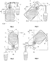
- the keg is positioned in the housing of the appliance with its longitudinal axis Y extending in the direction X 1 and with the dispensing opening at the neck portion of the container situated at the top level X 1,t of the container according to the gravitational direction X 1 .
- the cooling gun is directed to the neck portion and/or the shoulder portion of the container, which are in this case situated at the top third portion of the keg in the gravitational direction X 1 .
- FIG 2 an alternative embodiment of the appliance is represented, wherein the keg is positioned in the housing of the appliance with its longitudinal axis Y extending in the direction X 1 and with the dispensing opening at the neck portion of the container situated at the bottom level X 1,b of the container according to the gravitational direction X 1 .
- the cooling gun is directed to the base portion and/or the body portion of the container next to base portion, which are in this case situated at the top third portion of the keg in the gravitational direction X 1 .
- FIG 3 another alternative embodiment of the appliance is shown, wherein the keg is positioned in the housing with its longitudinal axis Y extending under a angle (a) with respect to the gravitational direction X 1 , with the dispense opening at the neck portion of the container located higher than the base portion in the gravitational field.
- the cooling gun is directed to the neck portion and/or the shoulder portion and/or the body portion of the container next to base portion, which are in this case situated at the top third portion of the keg in the gravitational direction X 1 .
- FIG 4 third alternative embodiment of the appliance is shown, wherein the keg is positioned in the housing with its longitudinal axis Y extending under a angle (a') with respect to the gravitational direction X 1 , with the dispense opening at the neck portion of the container located lower than the base portion in the gravitational field.
- the cooling gun is directed to the base portion and/or the body portion of the container, which are in this case situated at the top third portion P t of the keg in the gravitational direction X 1 .
- the cooling unit can be executed with a cold surface contacting the outer keg wall at a specific location, referred to as the cold area or impact area, instead of or in addition to the fluid gun.
- the cold surface extending in the inner space of the housing of the appliance and contacting the outer wall of the keg is hereby preferably coupled to the cold portion of an electrically driven peltier element.
- the location of the cold area or impact area is in this case in the top third portion of the keg according to the gravitational direction X 1 .
- the location of the impact area is preferably located such that it at least partially overlaps, correspond or comprises to a portion of the keg wherein the inner bag is in permanent contact with the outer container.
Landscapes
- Devices For Dispensing Beverages (AREA)
- Packages (AREA)
- Devices That Are Associated With Refrigeration Equipment (AREA)
Claims (8)
- Gerät zum Abgeben eines Getränks, wobei das Gerät Folgendes umfasst:- ein Gehäuse, das einen Innenraum (1') definiert, in dem ein Getränkfässchen (2) untergebracht ist, wobei das Fässchen (2) ein Fässchen vom Typ Beutelin-Behälter ist, das einen starren äußeren Behälter und einen quetschbaren Innenbeutel umfasst, wodurch beim Einfügen eines Antriebsmittels in dem Zwischenraum zwischen dem äußeren Behälter und dem Innenbeutel, der das Getränk enthält, der Innenbeutel gequetscht wird, wodurch das Getränk zum Abgeben herausgezwängt wird, wobei sich das Fässchen entlang einer Schwerkraftrichtung X1 parallel zu dem Schwerkraftfeld von einer oberen Position X1,t zu einer unteren Position X1,b erstreckt, wobei X1,t höher in dem Schwerkraftfeld ist als X1,b, wenn das Gerät (1) in Gebrauch ist;- eine Druckeinheit (6) zum Unterdrucksetzen des Zwischenraums zwischen dem äußeren Behälter und dem Innenbeutel des Fässchens (2);- eine Zapfhahneinheit (7), die das Abgeben von Getränk aus dem Fässchen (2) durch Druck angetrieben ermöglicht;- eine Kühleinheit (8) zum Kühlen des Getränks in dem Fässchen, wobei die Kühleinheit zum Kühlen einer spezifischen kalten Fläche der Außenwand des Fässchens auf eine Temperatur geeignet ist, die niedriger ist als eine beliebige andere Stelle des Fässchens,dadurch gekennzeichnet, dass die kalte Fläche des Fässchens (2) auf dem starren äußeren Behälter in dem oberen dritten Abschnitt des Fässchens entlang der Richtung X1 liegt.
- Gerät nach Anspruch 1, wobei der Innenbeutel und der starre Behälter mindestens eine permanente Kontaktstelle umfassen, wo der Innenbeutel den starren Behälter berührt, wobei die kalte Fläche an einer Lage auf der äußeren Oberfläche des Fässchens liegt, die der Lage entspricht, an der mindestens eine permanente Kontaktstelle liegt.
- Gerät nach einem der Ansprüche 1-2, wobei die kalte Fläche durch die Aufprallfläche eines kalten Fluidstroms, der zu dem Fässchen durch eine Fluidpistole (9) gerichtet ist, definiert ist.
- Gerät nach einem der Ansprüche 1-3, wobei das Gerät mindestens einen Einlass für Kühlfluid umfasst, der sich in dem Innenraum (1') erstreckt, und einen Auslass für das Kühlfluid in der Innenwand des Gehäuses, das den Innenraum definiert, wo Muldenkühlfluid aus dem Innenraum entfernt wird, wodurch ein Pfad für die Kühlflüssigkeit in dem Innenraum (1') von dem Einlass zu dem Auslass definiert wird.
- Gerät nach Anspruch 4, wobei die Distanz, senkrecht auf der Oberfläche der Innenwand des Gehäuses gemessen, zwischen der Fässchenaußenwand und der Innenwand des Gehäuses, das den Innenraum des Gehäuses definiert, mindestens entlang 50 % des Pfads des Kühlfluids in dem Innenraum kleiner ist als 1,5 cm.
- Gerät nach einem der Ansprüche 3-5, wobei die Kühlflüssigkeit aus der Gruppe ausgewählt ist, die folgende umfasst: Luft, Stickstoff, Kohlenstoffdioxid, Wasser, Salzsole, Glycol oder ein Gemisch davon.
- Gerät nach einem der Ansprüche 1-2, wobei die kalte Fläche durch eine Kontaktfläche mit einer gekühlten soliden Oberfläche definiert ist.
- Gerät nach einem der vorstehenden Ansprüche, wobei das Fässchen ein Getränkvolumen in dem Bereich von 0,5-20 Liter aufweist.
Applications Claiming Priority (2)
| Application Number | Priority Date | Filing Date | Title |
|---|---|---|---|
| EP14161327.3A EP2923997A1 (de) | 2014-03-24 | 2014-03-24 | Getränkespendeanwendung mit einer Kühleinheit |
| PCT/EP2015/056222 WO2015144685A1 (en) | 2014-03-24 | 2015-03-24 | Beverage dispensing appliance comprising a cooling unit |
Publications (2)
| Publication Number | Publication Date |
|---|---|
| EP3122683A1 EP3122683A1 (de) | 2017-02-01 |
| EP3122683B1 true EP3122683B1 (de) | 2019-05-01 |
Family
ID=50345889
Family Applications (2)
| Application Number | Title | Priority Date | Filing Date |
|---|---|---|---|
| EP14161327.3A Withdrawn EP2923997A1 (de) | 2014-03-24 | 2014-03-24 | Getränkespendeanwendung mit einer Kühleinheit |
| EP15711538.7A Active EP3122683B1 (de) | 2014-03-24 | 2015-03-24 | Getränkespendeanwendung mit einer kühleinheit |
Family Applications Before (1)
| Application Number | Title | Priority Date | Filing Date |
|---|---|---|---|
| EP14161327.3A Withdrawn EP2923997A1 (de) | 2014-03-24 | 2014-03-24 | Getränkespendeanwendung mit einer Kühleinheit |
Country Status (14)
| Country | Link |
|---|---|
| US (1) | US10252902B2 (de) |
| EP (2) | EP2923997A1 (de) |
| JP (1) | JP6632540B2 (de) |
| KR (1) | KR20160134691A (de) |
| CN (1) | CN106103334B (de) |
| AR (1) | AR099673A1 (de) |
| AU (1) | AU2015238459B2 (de) |
| BR (1) | BR112016021850B1 (de) |
| CA (1) | CA2943482C (de) |
| DK (1) | DK3122683T3 (de) |
| ES (1) | ES2739681T3 (de) |
| MX (1) | MX376614B (de) |
| RU (1) | RU2707461C2 (de) |
| WO (1) | WO2015144685A1 (de) |
Families Citing this family (17)
| Publication number | Priority date | Publication date | Assignee | Title |
|---|---|---|---|---|
| US20130264360A1 (en) * | 2012-04-05 | 2013-10-10 | Brewing Tools Llc | Reusable Vessel for Dispensing Beverages and Method of Storing and Dispensing Beverages |
| WO2018100424A1 (en) * | 2016-12-01 | 2018-06-07 | TACHENY Thierry | Box with inner bag for liquid food |
| US9919910B2 (en) * | 2016-02-23 | 2018-03-20 | John Delano Gibson | Fluid pressurization and dispensing system |
| NL2017109B1 (en) | 2016-07-05 | 2018-01-12 | Heineken Supply Chain Bv | Beverage dispensing assembly and beverage container |
| KR200484718Y1 (ko) * | 2017-02-16 | 2017-10-18 | 오비맥주 주식회사 | 일체형 생맥주 냉각장치 |
| NL2018955B1 (en) * | 2017-05-19 | 2018-11-28 | Heineken Supply Chain Bv | Beverage dispensing assembly and beverage container |
| NL2018956B1 (en) * | 2017-05-19 | 2018-11-28 | Heineken Supply Chain Bv | Beverage dispensing assembly and beverage container |
| KR102003804B1 (ko) * | 2017-08-04 | 2019-07-25 | 오비맥주 주식회사 | 생맥주 냉각장치 |
| KR102515595B1 (ko) * | 2017-11-16 | 2023-03-29 | 엘지전자 주식회사 | 음료 제조기 |
| US10773944B2 (en) * | 2018-04-03 | 2020-09-15 | Donald Christian Maier | Smart vessel containment and dispensing unit |
| CN110171794B (zh) * | 2019-05-10 | 2021-04-27 | 塔罗斯科技股份有限公司 | 一种液体容器 |
| JP6751877B1 (ja) * | 2020-04-22 | 2020-09-09 | クリップクリエイティブ合同会社 | 清酒サーバー及び清酒注出方法 |
| JP6868923B1 (ja) * | 2020-08-11 | 2021-05-12 | クリップクリエイティブ合同会社 | 発泡性清酒の製造方法 |
| KR102499515B1 (ko) * | 2020-11-05 | 2023-02-14 | 이용민 | 농축액 공급 유닛 및 이를 갖는 정수기 |
| JP2022128258A (ja) * | 2021-02-22 | 2022-09-01 | フジテクノ株式会社 | 飲料サーバー、および、飲料貯蔵容器の冷却方法 |
| CN112918920A (zh) * | 2021-03-11 | 2021-06-08 | 盈加科技(深圳)有限公司 | 一种用于酒类保鲜装置的中空针头插入结构 |
| JP7735219B2 (ja) * | 2022-05-20 | 2025-09-08 | キリンホールディングス株式会社 | 飲料サーバ |
Family Cites Families (20)
| Publication number | Priority date | Publication date | Assignee | Title |
|---|---|---|---|---|
| GB1537821A (en) * | 1975-01-09 | 1979-01-10 | Mk Refrigeration Ltd | Cooling apparatus |
| JPH0729660B2 (ja) * | 1987-05-15 | 1995-04-05 | 鐘淵化学工業株式会社 | 保冷容器 |
| JPS6458695A (en) * | 1987-08-21 | 1989-03-06 | Sharp Kk | Drink dispenser |
| JP2931495B2 (ja) * | 1993-03-25 | 1999-08-09 | 東芝機械株式会社 | 飲料容器及び容器内飲料の冷却注出方法 |
| GB2359065B (en) * | 2000-02-10 | 2004-04-28 | Imi Cornelius | Beverage dispense apparatus |
| JP2004067210A (ja) * | 2002-08-08 | 2004-03-04 | Fujimori Kogyo Co Ltd | 液体サーバー装置、サーバーおよびサーバーへの内袋取付方法 |
| NL1023429C2 (nl) * | 2003-05-14 | 2004-11-16 | Heineken Tech Services | Drankafgifte-inrichting. |
| ES2222812B1 (es) * | 2003-07-23 | 2006-03-16 | Jose Ramon Conde Hinojosa | Procedimiento y dispositivo de enfriamiento rapido de bebidas envasadas. |
| ZA200802226B (en) * | 2005-08-12 | 2009-10-28 | Carlsberg Breweries As | An assembly for dispensing beverage |
| JP4751932B2 (ja) | 2006-07-28 | 2011-08-17 | 富士通株式会社 | 位相検出装置および位相同期装置 |
| US20080260978A1 (en) | 2007-04-19 | 2008-10-23 | Inbev S.A. | Integral two layer preform, process and apparatus for the production thereof, process for producing a blow-moulded bag-in-container, and bag-in-container thus produced |
| US20080257883A1 (en) | 2007-04-19 | 2008-10-23 | Inbev S.A. | Integrally blow-moulded bag-in-container having an inner layer and the outer layer made of the same material and preform for making it |
| US20080257847A1 (en) | 2007-04-19 | 2008-10-23 | Inbev S.A. | Integrally blow-moulded bag-in-container having a bag anchoring point; process for the production thereof; and tool therefor |
| US20080258356A1 (en) | 2007-04-19 | 2008-10-23 | Inbev S.A. | Integrally blow-moulded bag-in-container comprising an inner layer and an outer layer comprising energy absorbing additives, and preform for making it |
| US20080257846A1 (en) | 2007-04-19 | 2008-10-23 | Inbev S.A. | Integrally blow-moulded bag-in-container having interface vents opening to the atmosphere at location adjacent to bag's mouth; preform for making it; and processes for producing the preform and bag-in-container |
| US8459503B2 (en) * | 2007-05-10 | 2013-06-11 | R. Clay Groesbeck | Temperature controlled liquid dispenser, containers therefore, and bag-in-box container construction |
| KR101780996B1 (ko) * | 2007-05-30 | 2017-10-23 | 코닌클리케 필립스 엔.브이. | 종이―기반 맥주 용기 및 그를 위한 분배 장치 |
| EP2025640A1 (de) * | 2007-08-10 | 2009-02-18 | Carlsberg Breweries A/S | Kühlvorrichtung für einen Getränkefass |
| CN101827779B (zh) * | 2007-08-20 | 2014-03-19 | 嘉士伯酿酒有限公司 | 用于饮料的模块式压力分配系统及用于该系统的模块 |
| US9701529B2 (en) * | 2011-06-24 | 2017-07-11 | RJ Enterprise, LLC | Method and apparatus for cooling a storage container for liquid |
-
2014
- 2014-03-24 EP EP14161327.3A patent/EP2923997A1/de not_active Withdrawn
-
2015
- 2015-03-05 AR ARP150100660A patent/AR099673A1/es active IP Right Grant
- 2015-03-24 EP EP15711538.7A patent/EP3122683B1/de active Active
- 2015-03-24 AU AU2015238459A patent/AU2015238459B2/en not_active Ceased
- 2015-03-24 RU RU2016140276A patent/RU2707461C2/ru active
- 2015-03-24 CA CA2943482A patent/CA2943482C/en active Active
- 2015-03-24 DK DK15711538.7T patent/DK3122683T3/da active
- 2015-03-24 JP JP2016557566A patent/JP6632540B2/ja not_active Expired - Fee Related
- 2015-03-24 WO PCT/EP2015/056222 patent/WO2015144685A1/en not_active Ceased
- 2015-03-24 MX MX2016012418A patent/MX376614B/es active IP Right Grant
- 2015-03-24 ES ES15711538T patent/ES2739681T3/es active Active
- 2015-03-24 CN CN201580015963.1A patent/CN106103334B/zh not_active Expired - Fee Related
- 2015-03-24 US US15/128,936 patent/US10252902B2/en active Active
- 2015-03-24 BR BR112016021850-7A patent/BR112016021850B1/pt not_active IP Right Cessation
- 2015-03-24 KR KR1020167026012A patent/KR20160134691A/ko not_active Abandoned
Non-Patent Citations (1)
| Title |
|---|
| None * |
Also Published As
| Publication number | Publication date |
|---|---|
| BR112016021850B1 (pt) | 2021-11-03 |
| RU2707461C2 (ru) | 2019-11-26 |
| CA2943482A1 (en) | 2015-10-01 |
| ES2739681T3 (es) | 2020-02-03 |
| US10252902B2 (en) | 2019-04-09 |
| EP2923997A1 (de) | 2015-09-30 |
| RU2016140276A3 (de) | 2018-09-10 |
| CN106103334B (zh) | 2019-07-30 |
| EP3122683A1 (de) | 2017-02-01 |
| AU2015238459B2 (en) | 2019-09-12 |
| US20170107092A1 (en) | 2017-04-20 |
| JP2017517445A (ja) | 2017-06-29 |
| CA2943482C (en) | 2023-02-28 |
| RU2016140276A (ru) | 2018-04-24 |
| MX2016012418A (es) | 2017-02-20 |
| KR20160134691A (ko) | 2016-11-23 |
| MX376614B (es) | 2025-03-07 |
| AU2015238459A1 (en) | 2016-09-01 |
| DK3122683T3 (da) | 2019-08-05 |
| CN106103334A (zh) | 2016-11-09 |
| AR099673A1 (es) | 2016-08-10 |
| WO2015144685A1 (en) | 2015-10-01 |
| BR112016021850A2 (pt) | 2021-08-24 |
| JP6632540B2 (ja) | 2020-01-22 |
Similar Documents
| Publication | Publication Date | Title |
|---|---|---|
| EP3122683B1 (de) | Getränkespendeanwendung mit einer kühleinheit | |
| CN109071198B (zh) | 致冷现调分配器 | |
| US10717637B2 (en) | Beverage dispensing device with mixing chamber and cooling functionality | |
| US7810679B2 (en) | Beer dispensing system with gas pressure reservoir | |
| US4437319A (en) | Beverage dispensing device | |
| US10866016B2 (en) | Heat exchanger | |
| US3283530A (en) | Beverage dispensing and cooling apparatus | |
| US20070051125A1 (en) | Portable apparatus for chilling draught beverages | |
| EP3303210A1 (de) | Vorrichtung zum ansaugen von getränken | |
| JP2010527862A (ja) | 複数の自己排出型飲料容器をタッピングするのに適した飲料回転式分配デバイス | |
| US11008205B2 (en) | Dispensing apparatus provided with a cooling unit | |
| JPH11208786A (ja) | 清涼飲料のディスペンサーにおける冷却装置 | |
| CN119013221B (zh) | 用于饮料分配系统的冷却设备 | |
| WO2009123493A1 (ru) | Устройство для ручного розлива пенящихся и/или газированных напитков | |
| WO2009044339A2 (en) | A beverage dispensing apparatus comprising a vessel with cooling means | |
| CN108151440A (zh) | 冷饮机 |
Legal Events
| Date | Code | Title | Description |
|---|---|---|---|
| STAA | Information on the status of an ep patent application or granted ep patent |
Free format text: STATUS: THE INTERNATIONAL PUBLICATION HAS BEEN MADE |
|
| PUAI | Public reference made under article 153(3) epc to a published international application that has entered the european phase |
Free format text: ORIGINAL CODE: 0009012 |
|
| STAA | Information on the status of an ep patent application or granted ep patent |
Free format text: STATUS: REQUEST FOR EXAMINATION WAS MADE |
|
| 17P | Request for examination filed |
Effective date: 20161024 |
|
| AK | Designated contracting states |
Kind code of ref document: A1 Designated state(s): AL AT BE BG CH CY CZ DE DK EE ES FI FR GB GR HR HU IE IS IT LI LT LU LV MC MK MT NL NO PL PT RO RS SE SI SK SM TR |
|
| AX | Request for extension of the european patent |
Extension state: BA ME |
|
| DAV | Request for validation of the european patent (deleted) | ||
| DAX | Request for extension of the european patent (deleted) | ||
| STAA | Information on the status of an ep patent application or granted ep patent |
Free format text: STATUS: EXAMINATION IS IN PROGRESS |
|
| 17Q | First examination report despatched |
Effective date: 20171122 |
|
| GRAP | Despatch of communication of intention to grant a patent |
Free format text: ORIGINAL CODE: EPIDOSNIGR1 |
|
| STAA | Information on the status of an ep patent application or granted ep patent |
Free format text: STATUS: GRANT OF PATENT IS INTENDED |
|
| INTG | Intention to grant announced |
Effective date: 20181030 |
|
| GRAS | Grant fee paid |
Free format text: ORIGINAL CODE: EPIDOSNIGR3 |
|
| GRAA | (expected) grant |
Free format text: ORIGINAL CODE: 0009210 |
|
| STAA | Information on the status of an ep patent application or granted ep patent |
Free format text: STATUS: THE PATENT HAS BEEN GRANTED |
|
| AK | Designated contracting states |
Kind code of ref document: B1 Designated state(s): AL AT BE BG CH CY CZ DE DK EE ES FI FR GB GR HR HU IE IS IT LI LT LU LV MC MK MT NL NO PL PT RO RS SE SI SK SM TR |
|
| REG | Reference to a national code |
Ref country code: GB Ref legal event code: FG4D |
|
| REG | Reference to a national code |
Ref country code: CH Ref legal event code: EP Ref country code: AT Ref legal event code: REF Ref document number: 1126669 Country of ref document: AT Kind code of ref document: T Effective date: 20190515 |
|
| REG | Reference to a national code |
Ref country code: DE Ref legal event code: R096 Ref document number: 602015029268 Country of ref document: DE |
|
| REG | Reference to a national code |
Ref country code: IE Ref legal event code: FG4D |
|
| REG | Reference to a national code |
Ref country code: NL Ref legal event code: FP |
|
| REG | Reference to a national code |
Ref country code: DK Ref legal event code: T3 Effective date: 20190731 |
|
| REG | Reference to a national code |
Ref country code: LT Ref legal event code: MG4D |
|
| PG25 | Lapsed in a contracting state [announced via postgrant information from national office to epo] |
Ref country code: HR Free format text: LAPSE BECAUSE OF FAILURE TO SUBMIT A TRANSLATION OF THE DESCRIPTION OR TO PAY THE FEE WITHIN THE PRESCRIBED TIME-LIMIT Effective date: 20190501 Ref country code: LT Free format text: LAPSE BECAUSE OF FAILURE TO SUBMIT A TRANSLATION OF THE DESCRIPTION OR TO PAY THE FEE WITHIN THE PRESCRIBED TIME-LIMIT Effective date: 20190501 Ref country code: FI Free format text: LAPSE BECAUSE OF FAILURE TO SUBMIT A TRANSLATION OF THE DESCRIPTION OR TO PAY THE FEE WITHIN THE PRESCRIBED TIME-LIMIT Effective date: 20190501 Ref country code: SE Free format text: LAPSE BECAUSE OF FAILURE TO SUBMIT A TRANSLATION OF THE DESCRIPTION OR TO PAY THE FEE WITHIN THE PRESCRIBED TIME-LIMIT Effective date: 20190501 Ref country code: AL Free format text: LAPSE BECAUSE OF FAILURE TO SUBMIT A TRANSLATION OF THE DESCRIPTION OR TO PAY THE FEE WITHIN THE PRESCRIBED TIME-LIMIT Effective date: 20190501 Ref country code: PT Free format text: LAPSE BECAUSE OF FAILURE TO SUBMIT A TRANSLATION OF THE DESCRIPTION OR TO PAY THE FEE WITHIN THE PRESCRIBED TIME-LIMIT Effective date: 20190901 Ref country code: NO Free format text: LAPSE BECAUSE OF FAILURE TO SUBMIT A TRANSLATION OF THE DESCRIPTION OR TO PAY THE FEE WITHIN THE PRESCRIBED TIME-LIMIT Effective date: 20190801 |
|
| PG25 | Lapsed in a contracting state [announced via postgrant information from national office to epo] |
Ref country code: LV Free format text: LAPSE BECAUSE OF FAILURE TO SUBMIT A TRANSLATION OF THE DESCRIPTION OR TO PAY THE FEE WITHIN THE PRESCRIBED TIME-LIMIT Effective date: 20190501 Ref country code: BG Free format text: LAPSE BECAUSE OF FAILURE TO SUBMIT A TRANSLATION OF THE DESCRIPTION OR TO PAY THE FEE WITHIN THE PRESCRIBED TIME-LIMIT Effective date: 20190801 Ref country code: GR Free format text: LAPSE BECAUSE OF FAILURE TO SUBMIT A TRANSLATION OF THE DESCRIPTION OR TO PAY THE FEE WITHIN THE PRESCRIBED TIME-LIMIT Effective date: 20190802 Ref country code: RS Free format text: LAPSE BECAUSE OF FAILURE TO SUBMIT A TRANSLATION OF THE DESCRIPTION OR TO PAY THE FEE WITHIN THE PRESCRIBED TIME-LIMIT Effective date: 20190501 |
|
| REG | Reference to a national code |
Ref country code: AT Ref legal event code: MK05 Ref document number: 1126669 Country of ref document: AT Kind code of ref document: T Effective date: 20190501 |
|
| PG25 | Lapsed in a contracting state [announced via postgrant information from national office to epo] |
Ref country code: IS Free format text: LAPSE BECAUSE OF FAILURE TO SUBMIT A TRANSLATION OF THE DESCRIPTION OR TO PAY THE FEE WITHIN THE PRESCRIBED TIME-LIMIT Effective date: 20190901 |
|
| PG25 | Lapsed in a contracting state [announced via postgrant information from national office to epo] |
Ref country code: RO Free format text: LAPSE BECAUSE OF FAILURE TO SUBMIT A TRANSLATION OF THE DESCRIPTION OR TO PAY THE FEE WITHIN THE PRESCRIBED TIME-LIMIT Effective date: 20190501 Ref country code: EE Free format text: LAPSE BECAUSE OF FAILURE TO SUBMIT A TRANSLATION OF THE DESCRIPTION OR TO PAY THE FEE WITHIN THE PRESCRIBED TIME-LIMIT Effective date: 20190501 Ref country code: AT Free format text: LAPSE BECAUSE OF FAILURE TO SUBMIT A TRANSLATION OF THE DESCRIPTION OR TO PAY THE FEE WITHIN THE PRESCRIBED TIME-LIMIT Effective date: 20190501 Ref country code: SK Free format text: LAPSE BECAUSE OF FAILURE TO SUBMIT A TRANSLATION OF THE DESCRIPTION OR TO PAY THE FEE WITHIN THE PRESCRIBED TIME-LIMIT Effective date: 20190501 |
|
| REG | Reference to a national code |
Ref country code: ES Ref legal event code: FG2A Ref document number: 2739681 Country of ref document: ES Kind code of ref document: T3 Effective date: 20200203 |
|
| REG | Reference to a national code |
Ref country code: DE Ref legal event code: R097 Ref document number: 602015029268 Country of ref document: DE |
|
| PG25 | Lapsed in a contracting state [announced via postgrant information from national office to epo] |
Ref country code: SM Free format text: LAPSE BECAUSE OF FAILURE TO SUBMIT A TRANSLATION OF THE DESCRIPTION OR TO PAY THE FEE WITHIN THE PRESCRIBED TIME-LIMIT Effective date: 20190501 |
|
| PLBE | No opposition filed within time limit |
Free format text: ORIGINAL CODE: 0009261 |
|
| STAA | Information on the status of an ep patent application or granted ep patent |
Free format text: STATUS: NO OPPOSITION FILED WITHIN TIME LIMIT |
|
| PG25 | Lapsed in a contracting state [announced via postgrant information from national office to epo] |
Ref country code: TR Free format text: LAPSE BECAUSE OF FAILURE TO SUBMIT A TRANSLATION OF THE DESCRIPTION OR TO PAY THE FEE WITHIN THE PRESCRIBED TIME-LIMIT Effective date: 20190501 |
|
| 26N | No opposition filed |
Effective date: 20200204 |
|
| PG25 | Lapsed in a contracting state [announced via postgrant information from national office to epo] |
Ref country code: PL Free format text: LAPSE BECAUSE OF FAILURE TO SUBMIT A TRANSLATION OF THE DESCRIPTION OR TO PAY THE FEE WITHIN THE PRESCRIBED TIME-LIMIT Effective date: 20190501 |
|
| PG25 | Lapsed in a contracting state [announced via postgrant information from national office to epo] |
Ref country code: SI Free format text: LAPSE BECAUSE OF FAILURE TO SUBMIT A TRANSLATION OF THE DESCRIPTION OR TO PAY THE FEE WITHIN THE PRESCRIBED TIME-LIMIT Effective date: 20190501 |
|
| PG25 | Lapsed in a contracting state [announced via postgrant information from national office to epo] |
Ref country code: MC Free format text: LAPSE BECAUSE OF FAILURE TO SUBMIT A TRANSLATION OF THE DESCRIPTION OR TO PAY THE FEE WITHIN THE PRESCRIBED TIME-LIMIT Effective date: 20190501 |
|
| REG | Reference to a national code |
Ref country code: CH Ref legal event code: PL |
|
| PG25 | Lapsed in a contracting state [announced via postgrant information from national office to epo] |
Ref country code: LU Free format text: LAPSE BECAUSE OF NON-PAYMENT OF DUE FEES Effective date: 20200324 |
|
| PG25 | Lapsed in a contracting state [announced via postgrant information from national office to epo] |
Ref country code: CH Free format text: LAPSE BECAUSE OF NON-PAYMENT OF DUE FEES Effective date: 20200331 Ref country code: LI Free format text: LAPSE BECAUSE OF NON-PAYMENT OF DUE FEES Effective date: 20200331 |
|
| PGFP | Annual fee paid to national office [announced via postgrant information from national office to epo] |
Ref country code: IE Payment date: 20210325 Year of fee payment: 7 Ref country code: CZ Payment date: 20210324 Year of fee payment: 7 |
|
| PGFP | Annual fee paid to national office [announced via postgrant information from national office to epo] |
Ref country code: DK Payment date: 20210323 Year of fee payment: 7 |
|
| PGFP | Annual fee paid to national office [announced via postgrant information from national office to epo] |
Ref country code: ES Payment date: 20210525 Year of fee payment: 7 |
|
| PG25 | Lapsed in a contracting state [announced via postgrant information from national office to epo] |
Ref country code: MT Free format text: LAPSE BECAUSE OF FAILURE TO SUBMIT A TRANSLATION OF THE DESCRIPTION OR TO PAY THE FEE WITHIN THE PRESCRIBED TIME-LIMIT Effective date: 20190501 Ref country code: CY Free format text: LAPSE BECAUSE OF FAILURE TO SUBMIT A TRANSLATION OF THE DESCRIPTION OR TO PAY THE FEE WITHIN THE PRESCRIBED TIME-LIMIT Effective date: 20190501 |
|
| PG25 | Lapsed in a contracting state [announced via postgrant information from national office to epo] |
Ref country code: MK Free format text: LAPSE BECAUSE OF FAILURE TO SUBMIT A TRANSLATION OF THE DESCRIPTION OR TO PAY THE FEE WITHIN THE PRESCRIBED TIME-LIMIT Effective date: 20190501 |
|
| REG | Reference to a national code |
Ref country code: DK Ref legal event code: EBP Effective date: 20220331 |
|
| PG25 | Lapsed in a contracting state [announced via postgrant information from national office to epo] |
Ref country code: CZ Free format text: LAPSE BECAUSE OF NON-PAYMENT OF DUE FEES Effective date: 20220324 |
|
| PG25 | Lapsed in a contracting state [announced via postgrant information from national office to epo] |
Ref country code: IE Free format text: LAPSE BECAUSE OF NON-PAYMENT OF DUE FEES Effective date: 20220324 |
|
| PG25 | Lapsed in a contracting state [announced via postgrant information from national office to epo] |
Ref country code: DK Free format text: LAPSE BECAUSE OF NON-PAYMENT OF DUE FEES Effective date: 20220331 |
|
| REG | Reference to a national code |
Ref country code: ES Ref legal event code: FD2A Effective date: 20230508 |
|
| P01 | Opt-out of the competence of the unified patent court (upc) registered |
Effective date: 20230527 |
|
| PG25 | Lapsed in a contracting state [announced via postgrant information from national office to epo] |
Ref country code: ES Free format text: LAPSE BECAUSE OF NON-PAYMENT OF DUE FEES Effective date: 20220325 |
|
| PGFP | Annual fee paid to national office [announced via postgrant information from national office to epo] |
Ref country code: NL Payment date: 20240320 Year of fee payment: 10 |
|
| PGFP | Annual fee paid to national office [announced via postgrant information from national office to epo] |
Ref country code: DE Payment date: 20240320 Year of fee payment: 10 Ref country code: GB Payment date: 20240320 Year of fee payment: 10 |
|
| PGFP | Annual fee paid to national office [announced via postgrant information from national office to epo] |
Ref country code: IT Payment date: 20240329 Year of fee payment: 10 Ref country code: FR Payment date: 20240328 Year of fee payment: 10 Ref country code: BE Payment date: 20240320 Year of fee payment: 10 |
|
| REG | Reference to a national code |
Ref country code: DE Ref legal event code: R119 Ref document number: 602015029268 Country of ref document: DE |
|
| REG | Reference to a national code |
Ref country code: NL Ref legal event code: MM Effective date: 20250401 |
|
| GBPC | Gb: european patent ceased through non-payment of renewal fee |
Effective date: 20250324 |
|
| REG | Reference to a national code |
Ref country code: BE Ref legal event code: MM Effective date: 20250331 |
|
| PG25 | Lapsed in a contracting state [announced via postgrant information from national office to epo] |
Ref country code: NL Free format text: LAPSE BECAUSE OF NON-PAYMENT OF DUE FEES Effective date: 20250401 |
|
| PG25 | Lapsed in a contracting state [announced via postgrant information from national office to epo] |
Ref country code: DE Free format text: LAPSE BECAUSE OF NON-PAYMENT OF DUE FEES Effective date: 20251001 |
|
| PG25 | Lapsed in a contracting state [announced via postgrant information from national office to epo] |
Ref country code: GB Free format text: LAPSE BECAUSE OF NON-PAYMENT OF DUE FEES Effective date: 20250324 |
|
| PG25 | Lapsed in a contracting state [announced via postgrant information from national office to epo] |
Ref country code: IT Free format text: LAPSE BECAUSE OF NON-PAYMENT OF DUE FEES Effective date: 20250324 Ref country code: FR Free format text: LAPSE BECAUSE OF NON-PAYMENT OF DUE FEES Effective date: 20250331 |
|
| PG25 | Lapsed in a contracting state [announced via postgrant information from national office to epo] |
Ref country code: BE Free format text: LAPSE BECAUSE OF NON-PAYMENT OF DUE FEES Effective date: 20250331 |