EP3124370A2 - Automatic brake device for saddle riding type vehicle - Google Patents
Automatic brake device for saddle riding type vehicle Download PDFInfo
- Publication number
- EP3124370A2 EP3124370A2 EP16174969.2A EP16174969A EP3124370A2 EP 3124370 A2 EP3124370 A2 EP 3124370A2 EP 16174969 A EP16174969 A EP 16174969A EP 3124370 A2 EP3124370 A2 EP 3124370A2
- Authority
- EP
- European Patent Office
- Prior art keywords
- brake
- automatic brake
- rear brakes
- braking
- limit
- Prior art date
- Legal status (The legal status is an assumption and is not a legal conclusion. Google has not performed a legal analysis and makes no representation as to the accuracy of the status listed.)
- Granted
Links
Images


Classifications
-
- B—PERFORMING OPERATIONS; TRANSPORTING
- B60—VEHICLES IN GENERAL
- B60T—VEHICLE BRAKE CONTROL SYSTEMS OR PARTS THEREOF; BRAKE CONTROL SYSTEMS OR PARTS THEREOF, IN GENERAL; ARRANGEMENT OF BRAKING ELEMENTS ON VEHICLES IN GENERAL; PORTABLE DEVICES FOR PREVENTING UNWANTED MOVEMENT OF VEHICLES; VEHICLE MODIFICATIONS TO FACILITATE COOLING OF BRAKES
- B60T7/00—Brake-action initiating means
- B60T7/12—Brake-action initiating means for automatic initiation; for initiation not subject to will of driver or passenger
- B60T7/22—Brake-action initiating means for automatic initiation; for initiation not subject to will of driver or passenger initiated by contact of vehicle, e.g. bumper, with an external object, e.g. another vehicle, or by means of contactless obstacle detectors mounted on the vehicle
-
- B—PERFORMING OPERATIONS; TRANSPORTING
- B60—VEHICLES IN GENERAL
- B60L—PROPULSION OF ELECTRICALLY-PROPELLED VEHICLES; SUPPLYING ELECTRIC POWER FOR AUXILIARY EQUIPMENT OF ELECTRICALLY-PROPELLED VEHICLES; ELECTRODYNAMIC BRAKE SYSTEMS FOR VEHICLES IN GENERAL; MAGNETIC SUSPENSION OR LEVITATION FOR VEHICLES; MONITORING OPERATING VARIABLES OF ELECTRICALLY-PROPELLED VEHICLES; ELECTRIC SAFETY DEVICES FOR ELECTRICALLY-PROPELLED VEHICLES
- B60L3/00—Electric devices on electrically-propelled vehicles for safety purposes; Monitoring operating variables, e.g. speed, deceleration or energy consumption
- B60L3/0007—Measures or means for preventing or attenuating collisions
-
- B—PERFORMING OPERATIONS; TRANSPORTING
- B60—VEHICLES IN GENERAL
- B60L—PROPULSION OF ELECTRICALLY-PROPELLED VEHICLES; SUPPLYING ELECTRIC POWER FOR AUXILIARY EQUIPMENT OF ELECTRICALLY-PROPELLED VEHICLES; ELECTRODYNAMIC BRAKE SYSTEMS FOR VEHICLES IN GENERAL; MAGNETIC SUSPENSION OR LEVITATION FOR VEHICLES; MONITORING OPERATING VARIABLES OF ELECTRICALLY-PROPELLED VEHICLES; ELECTRIC SAFETY DEVICES FOR ELECTRICALLY-PROPELLED VEHICLES
- B60L7/00—Electrodynamic brake systems for vehicles in general
- B60L7/24—Electrodynamic brake systems for vehicles in general with additional mechanical or electromagnetic braking
- B60L7/26—Controlling the braking effect
-
- B—PERFORMING OPERATIONS; TRANSPORTING
- B60—VEHICLES IN GENERAL
- B60T—VEHICLE BRAKE CONTROL SYSTEMS OR PARTS THEREOF; BRAKE CONTROL SYSTEMS OR PARTS THEREOF, IN GENERAL; ARRANGEMENT OF BRAKING ELEMENTS ON VEHICLES IN GENERAL; PORTABLE DEVICES FOR PREVENTING UNWANTED MOVEMENT OF VEHICLES; VEHICLE MODIFICATIONS TO FACILITATE COOLING OF BRAKES
- B60T7/00—Brake-action initiating means
- B60T7/02—Brake-action initiating means for personal initiation
- B60T7/04—Brake-action initiating means for personal initiation foot actuated
- B60T7/042—Brake-action initiating means for personal initiation foot actuated by electrical means, e.g. using travel or force sensors
-
- B—PERFORMING OPERATIONS; TRANSPORTING
- B60—VEHICLES IN GENERAL
- B60T—VEHICLE BRAKE CONTROL SYSTEMS OR PARTS THEREOF; BRAKE CONTROL SYSTEMS OR PARTS THEREOF, IN GENERAL; ARRANGEMENT OF BRAKING ELEMENTS ON VEHICLES IN GENERAL; PORTABLE DEVICES FOR PREVENTING UNWANTED MOVEMENT OF VEHICLES; VEHICLE MODIFICATIONS TO FACILITATE COOLING OF BRAKES
- B60T7/00—Brake-action initiating means
- B60T7/02—Brake-action initiating means for personal initiation
- B60T7/08—Brake-action initiating means for personal initiation hand actuated
- B60T7/085—Brake-action initiating means for personal initiation hand actuated by electrical means, e.g. travel, force sensors
-
- B—PERFORMING OPERATIONS; TRANSPORTING
- B60—VEHICLES IN GENERAL
- B60T—VEHICLE BRAKE CONTROL SYSTEMS OR PARTS THEREOF; BRAKE CONTROL SYSTEMS OR PARTS THEREOF, IN GENERAL; ARRANGEMENT OF BRAKING ELEMENTS ON VEHICLES IN GENERAL; PORTABLE DEVICES FOR PREVENTING UNWANTED MOVEMENT OF VEHICLES; VEHICLE MODIFICATIONS TO FACILITATE COOLING OF BRAKES
- B60T8/00—Arrangements for adjusting wheel-braking force to meet varying vehicular or ground-surface conditions, e.g. limiting or varying distribution of braking force
- B60T8/17—Using electrical or electronic regulation means to control braking
- B60T8/1701—Braking or traction control means specially adapted for particular types of vehicles
- B60T8/1706—Braking or traction control means specially adapted for particular types of vehicles for single-track vehicles, e.g. motorcycles
-
- B—PERFORMING OPERATIONS; TRANSPORTING
- B60—VEHICLES IN GENERAL
- B60T—VEHICLE BRAKE CONTROL SYSTEMS OR PARTS THEREOF; BRAKE CONTROL SYSTEMS OR PARTS THEREOF, IN GENERAL; ARRANGEMENT OF BRAKING ELEMENTS ON VEHICLES IN GENERAL; PORTABLE DEVICES FOR PREVENTING UNWANTED MOVEMENT OF VEHICLES; VEHICLE MODIFICATIONS TO FACILITATE COOLING OF BRAKES
- B60T8/00—Arrangements for adjusting wheel-braking force to meet varying vehicular or ground-surface conditions, e.g. limiting or varying distribution of braking force
- B60T8/17—Using electrical or electronic regulation means to control braking
- B60T8/176—Brake regulation specially adapted to prevent excessive wheel slip during vehicle deceleration, e.g. ABS
- B60T8/1766—Proportioning of brake forces according to vehicle axle loads, e.g. front to rear of vehicle
-
- B—PERFORMING OPERATIONS; TRANSPORTING
- B60—VEHICLES IN GENERAL
- B60T—VEHICLE BRAKE CONTROL SYSTEMS OR PARTS THEREOF; BRAKE CONTROL SYSTEMS OR PARTS THEREOF, IN GENERAL; ARRANGEMENT OF BRAKING ELEMENTS ON VEHICLES IN GENERAL; PORTABLE DEVICES FOR PREVENTING UNWANTED MOVEMENT OF VEHICLES; VEHICLE MODIFICATIONS TO FACILITATE COOLING OF BRAKES
- B60T8/00—Arrangements for adjusting wheel-braking force to meet varying vehicular or ground-surface conditions, e.g. limiting or varying distribution of braking force
- B60T8/32—Arrangements for adjusting wheel-braking force to meet varying vehicular or ground-surface conditions, e.g. limiting or varying distribution of braking force responsive to a speed condition, e.g. acceleration or deceleration
- B60T8/321—Arrangements for adjusting wheel-braking force to meet varying vehicular or ground-surface conditions, e.g. limiting or varying distribution of braking force responsive to a speed condition, e.g. acceleration or deceleration deceleration
- B60T8/3225—Systems specially adapted for single-track vehicles, e.g. motorcycles
-
- B—PERFORMING OPERATIONS; TRANSPORTING
- B60—VEHICLES IN GENERAL
- B60W—CONJOINT CONTROL OF VEHICLE SUB-UNITS OF DIFFERENT TYPE OR DIFFERENT FUNCTION; CONTROL SYSTEMS SPECIALLY ADAPTED FOR HYBRID VEHICLES; ROAD VEHICLE DRIVE CONTROL SYSTEMS FOR PURPOSES NOT RELATED TO THE CONTROL OF A PARTICULAR SUB-UNIT
- B60W30/00—Purposes of road vehicle drive control systems not related to the control of a particular sub-unit, e.g. of systems using conjoint control of vehicle sub-units
- B60W30/08—Active safety systems predicting or avoiding probable or impending collision or attempting to minimise its consequences
- B60W30/09—Taking automatic action to avoid collision, e.g. braking and steering
-
- B—PERFORMING OPERATIONS; TRANSPORTING
- B62—LAND VEHICLES FOR TRAVELLING OTHERWISE THAN ON RAILS
- B62J—CYCLE SADDLES OR SEATS; AUXILIARY DEVICES OR ACCESSORIES SPECIALLY ADAPTED TO CYCLES AND NOT OTHERWISE PROVIDED FOR, e.g. ARTICLE CARRIERS OR CYCLE PROTECTORS
- B62J27/00—Safety equipment
-
- B—PERFORMING OPERATIONS; TRANSPORTING
- B62—LAND VEHICLES FOR TRAVELLING OTHERWISE THAN ON RAILS
- B62J—CYCLE SADDLES OR SEATS; AUXILIARY DEVICES OR ACCESSORIES SPECIALLY ADAPTED TO CYCLES AND NOT OTHERWISE PROVIDED FOR, e.g. ARTICLE CARRIERS OR CYCLE PROTECTORS
- B62J45/00—Electrical equipment arrangements specially adapted for use as accessories on cycles, not otherwise provided for
- B62J45/40—Sensor arrangements; Mounting thereof
- B62J45/41—Sensor arrangements; Mounting thereof characterised by the type of sensor
- B62J45/412—Speed sensors
-
- B—PERFORMING OPERATIONS; TRANSPORTING
- B62—LAND VEHICLES FOR TRAVELLING OTHERWISE THAN ON RAILS
- B62L—BRAKES SPECIALLY ADAPTED FOR CYCLES
- B62L3/00—Brake-actuating mechanisms; Arrangements thereof
- B62L3/02—Brake-actuating mechanisms; Arrangements thereof for control by a hand lever
- B62L3/023—Brake-actuating mechanisms; Arrangements thereof for control by a hand lever acting on fluid pressure systems
-
- B—PERFORMING OPERATIONS; TRANSPORTING
- B62—LAND VEHICLES FOR TRAVELLING OTHERWISE THAN ON RAILS
- B62L—BRAKES SPECIALLY ADAPTED FOR CYCLES
- B62L3/00—Brake-actuating mechanisms; Arrangements thereof
- B62L3/08—Mechanisms specially adapted for braking more than one wheel
-
- B—PERFORMING OPERATIONS; TRANSPORTING
- B60—VEHICLES IN GENERAL
- B60L—PROPULSION OF ELECTRICALLY-PROPELLED VEHICLES; SUPPLYING ELECTRIC POWER FOR AUXILIARY EQUIPMENT OF ELECTRICALLY-PROPELLED VEHICLES; ELECTRODYNAMIC BRAKE SYSTEMS FOR VEHICLES IN GENERAL; MAGNETIC SUSPENSION OR LEVITATION FOR VEHICLES; MONITORING OPERATING VARIABLES OF ELECTRICALLY-PROPELLED VEHICLES; ELECTRIC SAFETY DEVICES FOR ELECTRICALLY-PROPELLED VEHICLES
- B60L2240/00—Control parameters of input or output; Target parameters
- B60L2240/40—Drive Train control parameters
- B60L2240/46—Drive Train control parameters related to wheels
- B60L2240/461—Speed
-
- B—PERFORMING OPERATIONS; TRANSPORTING
- B60—VEHICLES IN GENERAL
- B60T—VEHICLE BRAKE CONTROL SYSTEMS OR PARTS THEREOF; BRAKE CONTROL SYSTEMS OR PARTS THEREOF, IN GENERAL; ARRANGEMENT OF BRAKING ELEMENTS ON VEHICLES IN GENERAL; PORTABLE DEVICES FOR PREVENTING UNWANTED MOVEMENT OF VEHICLES; VEHICLE MODIFICATIONS TO FACILITATE COOLING OF BRAKES
- B60T2201/00—Particular use of vehicle brake systems; Special systems using also the brakes; Special software modules within the brake system controller
- B60T2201/02—Active or adaptive cruise control system; Distance control
- B60T2201/022—Collision avoidance systems
-
- B—PERFORMING OPERATIONS; TRANSPORTING
- B60—VEHICLES IN GENERAL
- B60W—CONJOINT CONTROL OF VEHICLE SUB-UNITS OF DIFFERENT TYPE OR DIFFERENT FUNCTION; CONTROL SYSTEMS SPECIALLY ADAPTED FOR HYBRID VEHICLES; ROAD VEHICLE DRIVE CONTROL SYSTEMS FOR PURPOSES NOT RELATED TO THE CONTROL OF A PARTICULAR SUB-UNIT
- B60W2300/00—Indexing codes relating to the type of vehicle
- B60W2300/36—Cycles; Motorcycles; Scooters
-
- B—PERFORMING OPERATIONS; TRANSPORTING
- B60—VEHICLES IN GENERAL
- B60W—CONJOINT CONTROL OF VEHICLE SUB-UNITS OF DIFFERENT TYPE OR DIFFERENT FUNCTION; CONTROL SYSTEMS SPECIALLY ADAPTED FOR HYBRID VEHICLES; ROAD VEHICLE DRIVE CONTROL SYSTEMS FOR PURPOSES NOT RELATED TO THE CONTROL OF A PARTICULAR SUB-UNIT
- B60W2710/00—Output or target parameters relating to a particular sub-units
- B60W2710/18—Braking system
- B60W2710/182—Brake pressure, e.g. of fluid or between pad and disc
-
- B—PERFORMING OPERATIONS; TRANSPORTING
- B60—VEHICLES IN GENERAL
- B60Y—INDEXING SCHEME RELATING TO ASPECTS CROSS-CUTTING VEHICLE TECHNOLOGY
- B60Y2200/00—Type of vehicle
- B60Y2200/10—Road Vehicles
- B60Y2200/12—Motorcycles, Trikes; Quads; Scooters
Definitions
- the present invention relates to an automatic brake device for a saddle riding type vehicle.
- an automatic brake device for a vehicle which uses, for automatic brake control of the vehicle, the speed of the own vehicle and a target deceleration set when avoiding contact of the own vehicle with a front obstacle (see JP 1999-14648 A , for example).
- an automatic brake device as described above is applied to a saddle riding type vehicle such as a motorcycle or the like, it is desirable not only to avoid contact with a front obstacle but also to consider reduction of a feeling of strangeness of a driver at a time of automatic brake control.
- an automatic brake device for a saddle riding type vehicle.
- the automatic brake device includes a front brake (2) and a rear brake (3) capable of being actuated independently of each other and a brake modulator (10) configured to control actuation of the front and rear brakes (2, 3).
- the brake modulator (10) includes collision possibility determining means (19) for determining a possibility of collision of the own vehicle with a front obstacle, automatic brake control means (21) for performing automatic brake control that automatically increases braking forces of the front and rear brakes (2, 3) when the collision possibility determining means (19) determines that there is a possibility of collision, and brake operation determining means (20) for determining presence or absence of brake operation by a driver of the own vehicle.
- the automatic brake control means (21) changes a manner of increasing the braking forces of the front and rear brakes (2, 3) according to the brake operation by the driver.
- the saddle riding type vehicle includes vehicles in general to be ridden by a driver straddling a vehicle body.
- the saddle riding type vehicle includes not only motorcycles (including motor-assisted bicycles and motor scooter type vehicles) but also three-wheeled vehicles (including not only vehicles having one front wheel and two rear wheels but also vehicles having two front wheels and one rear wheel) or four-wheeled vehicles.
- the automatic brake control means (21) includes limit braking necessity determining means (22) for determining whether to increase the braking forces of the front and rear brakes (2, 3) while maintaining a ratio between operations of the front and rear brakes (2, 3) by the driver or to make the front and rear brakes (2, 3) reach a limit braking state without maintaining the ratio between the operations.
- the brake modulator (10) includes a memory (16) configured to store a braking force map (M) having an axis of ordinates indicating magnitude of the braking force of one of the front and rear brakes (2, 3) and having an axis of abscissas indicating magnitude of the braking force of the other of the front and rear brakes (2, 3).
- a limit line (E) and a limit line (C) respectively indicating braking forces as lock limits of the front and rear brakes (2, 3) are described in the braking force map (M).
- the automatic brake control means (21) actuates the front and rear brakes (2, 3) so as to reach the limit line (E) and the limit line (C), respectively, in the braking force map (M).
- the brake modulator (10) includes friction coefficient estimating means (17) for estimating a road surface friction coefficient.
- a plurality of limit lines (E) and a plurality of limit lines (C) are described according to the road surface friction coefficient.
- the automatic brake control means (21) selects the limit line (E) and the limit line (C) according to the road surface friction coefficient.
- switching can be performed between performing automatic brake control that reduces a feeling of strangeness by maintaining the ratio between the operations of the front and rear brakes and performing limit braking of the front and rear brakes immediately regardless of the ratio between the operations of the front and rear brakes.
- automatic brake control can be performed easily by referring to the control force map.
- limit braking of the front and rear brakes can be performed according to the estimated road surface friction coefficient.
- a brake control device 1 according to the present embodiment is for example applied to a saddle riding type vehicle such as a motorcycle having a front wheel and a rear wheel or the like.
- the brake control device 1 has a front brake 2 and a rear brake 3 that are provided independently of each other.
- the front brake 2 is configured as a hydraulic disk brake including a front brake disk 4 attached to a front wheel of the saddle riding type vehicle so as to be rotatable integrally with the front wheel and a front brake caliper 6 supplied with a hydraulic pressure (oil pressure) to clamp the front brake disk 4.
- the rear brake 3 is configured as a hydraulic disk brake including a rear brake disk 5 attached to a rear wheel of the saddle riding type vehicle so as to be rotatable integrally with the rear wheel and a rear brake caliper 7 supplied with a hydraulic pressure (oil pressure) to clamp the rear brake disk 5.
- the brake control device 1 has a front master cylinder 8 and a rear master cylinder 9 provided independently of each other.
- the front master cylinder 8 is coupled with a front brake operating element 8a such as a brake lever or the like.
- the front master cylinder 8 generates a hydraulic pressure (oil pressure) according to an operation of the front brake operating element 8a.
- the rear master cylinder 9 is coupled with a rear brake operating element 9a such as a brake pedal or the like.
- the rear master cylinder 9 generates a hydraulic pressure (oil pressure) according to an operation of the rear brake operating element 9a.
- the brake control device 1 has a brake modulator 10 interposed between the front and rear master cylinders 8 and 9 and the front and rear brake calipers 6 and 7.
- the brake control device 1 constitutes a so-called by-wire type brake system that electrically links the front and rear master cylinders 8 and 9 to the front and rear brake calipers 6 and 7.
- the brake modulator 10 includes: a hydraulic circuit unit 11 that can change a hydraulic passage and which has oil pressure generating means 11a such as a pump or the like; and an electronic control unit (ECU) 12 that controls actuation of the hydraulic circuit unit 11.
- a hydraulic circuit unit 11 that can change a hydraulic passage and which has oil pressure generating means 11a such as a pump or the like
- ECU electronic control unit
- the front and rear master cylinders 8 and 9 are coupled to the front and rear brake calipers 6 and 7 via the hydraulic circuit unit 11.
- the hydraulic circuit unit 11 at normal times blocks communication between the front and rear master cylinders 8 and 9 and the front and rear brake calipers 6 and 7, and generates, in the oil pressure generating means 11a, an oil pressure corresponding to oil pressures generated in the front and rear master cylinders 8 and 9.
- the brake modulator 10 supplies the oil pressure generated by the hydraulic circuit unit 11 to the front and rear brake calipers 6 and 7 as appropriate, thereby generating braking forces in the front and rear brakes 2 and 3.
- the oil pressures generated in the front and rear master cylinders 8 and 9 can be supplied to the front and rear brake calipers 6 and 7.
- the brake modulator 10 can generate braking forces in the front and rear brakes 2 and 3 as appropriate by performing automatic brake control based on various kinds of information including vehicle information separately from operation of the front and rear brake operating elements 8a and 9a by a driver.
- the ECU 12 is supplied with detection information about amounts of operation of the front and rear brake operating elements 8a and 9a, detection information of outside recognizing means 13 to be described later, and detection information of wheel speed sensors 14 and 15 for the front and rear wheels.
- the brake modulator 10 generates an oil pressure corresponding to the amounts of operation of the front and rear brake operating elements 8a and 9a in the oil pressure generating means 11a of the hydraulic circuit unit 11, and supplies the oil pressure to the front and rear brake calipers 6 and 7.
- the brake modulator 10 can generate braking forces in the front and rear brakes 2 and 3, and perform automatic brake control not depending on the amounts of operation of the front and rear brake operating elements 8a and 9a.
- the outside recognizing means 13 includes for example a radar device installed in a front end portion of the saddle riding type vehicle.
- the radar device emits electromagnetic waves such as millimeter waves or the like toward the front of the vehicle in predetermined control cycles, and receives the reflected waves.
- the ECU 12 determines whether or not there is an obstacle in front of the vehicle (including another vehicle) on the basis of a state of transmission and reception of millimeter waves in the radar device, and when there is an obstacle, calculates a distance and a speed relative to the obstacle.
- the obstacle will hereinafter be referred to as a front obstacle.
- the outside recognizing means 13 may use a camera besides the radar device, and may be a configuration combining transmission and reception information of the radar device and imaging information of the camera.
- the ECU 12 is formed by a microcomputer including a central processing unit, a memory, and an input-output interface as hardware (only the memory is depicted by reference numeral 16).
- the ECU 12 performs various kinds of control processing according to detection signals of various kinds of sensors or switches and outside recognition information or the like.
- the ECU 12 performs anti-lock brake control (ABS control) and automatic brake control to be described later or the like by controlling actuation of the front and rear brakes 2 and 3 on the basis of a program stored in the memory 16.
- the ECU 12 includes a friction coefficient estimating unit 17 that performs processing of estimating a road surface friction coefficient.
- the road surface friction coefficient is estimated by calculating the friction coefficient according to a difference between the wheel speeds of the front and rear wheels. Used as the difference between the wheel speeds of the front and rear wheels is for example a difference between the wheel speeds of the rear wheel as a driving wheel and the front wheel as a driven wheel, a difference between the wheel speeds of the front and rear wheels due to a momentary actuation of the brake modulator 10, or the like.
- the memory 16 of the ECU 12 stores a braking force map M for the front and rear wheels.
- the braking force map M for example has an axis of ordinates indicating the braking force of the rear brake 3 and an axis of abscissas indicating the braking force of the front brake 2.
- a curve A represents an ideal increase curve of the braking forces of the front and rear brakes 2 and 3.
- a right end Z of the curve A in FIG. 2 is a front-rear braking limit point at which the saddle riding type vehicle produces a maximum deceleration by the combination of the front and rear brakes 2 and 3, and is a front-rear lock limit point indicating that increasing the braking forces to this point or more locks at least one of the front and rear wheels.
- a point B on the axis of ordinates is a rear wheel braking limit point when only the rear brake 3 is actuated, and is a rear lock limit point indicating that increasing the rear wheel braking force to this point or more locks the rear wheel.
- a straight line C from the rear lock limit point B to the front-rear lock limit point Z is a rear brake limit line indicating a braking force as a lock limit of the rear brake 3.
- a point D on the axis of abscissas is a front wheel braking limit point when only the front brake 2 is actuated, and is a front lock limit point indicating that increasing the front wheel braking force to this point or more locks the front wheel.
- a straight line E from the front lock limit point D to the front-rear lock limit point Z is a front brake limit line indicating a braking force as a lock limit of the front brake 2.
- a region F defined by the front and rear brake limit lines E and C is set as a non-lock region in which the locking of the front and rear wheels by the front and rear brakes 2 and 3 can be avoided.
- a plurality of front brake limit lines E and a plurality of rear brake limit lines C are set according to the road surface friction coefficient.
- the front and rear brake limit lines E and C used in automatic brake control are selected according to the road surface friction coefficient estimated by the friction coefficient estimating unit 17.
- a small road surface friction coefficient is calculated which is at a level obtained by dividing the estimated road surface friction coefficient by a safety factor (for example 1.2 or the like).
- a region G defined by front and rear brake limit lines E' and C' corresponding to the small road surface friction coefficient at this level is set as a collision possibility determination region used in collision possibility determination to be described later.
- the front and rear brake limit lines E' and C' intersect each other at a point of intersection Z' on the curve A.
- the point of intersection Z' corresponds to an upper limit braking force in the collision possibility determination region G.
- the ECU 12 includes: a brake control unit 18 performing normal brake control that actuates the front and rear brakes 2 and 3 according to input from the front and rear brake operating elements 8a and 9a, anti-lock brake control that avoids the locking of the front and rear wheels by the brakes, and the like; a collision possibility determining unit 19 determining a possibility of collision of the saddle riding type vehicle with a front obstacle on the basis of the detection information of the outside recognizing means 13 and the front and rear wheel speed sensors 14 and 15; a brake operation determining unit 20 determining conditions such as the presence or absence of brake operation by the driver of the saddle riding type vehicle, amounts of the operation, and the like; and an automatic brake control unit 21 performing automatic brake control that actuates the front and rear brakes 2 and 3 more strongly than the normal brake control according to the conditions of the brake operation (automatically increases the braking forces of the front and rear brakes 2 and 3) when the collision possibility determining unit 19 determines that there is a possibility of collision.
- a brake control unit 18 performing normal brake control that actu
- the collision possibility determining unit 19 determines the possibility of collision of the saddle riding type vehicle with a front obstacle. Specifically, the collision possibility determining unit 19 obtains information about the presence or absence of a front obstacle, a relative distance and a relative speed between the front obstacle and the saddle riding type vehicle, and the like on the basis of detection values of the outside recognizing means 13, and calculates the vehicle speed of the saddle riding type vehicle on the basis of detection values of the wheel speed sensors 14 and 15.
- the collision possibility determining unit 19 determines whether or not there is a possibility of collision with the front obstacle even when a braking force at the upper limit (for example the point of intersection Z') in the collision possibility determination region G of the braking force map M acts on the saddle riding type vehicle having the calculated vehicle speed.
- step S1 When the determination in step S1 is NO (there is no possibility of collision), the present processing is directly ended.
- step S1 the determination in step S1 is YES (there is a possibility of collision)
- the processing proceeds to step S2, where the automatic brake control unit 21 performs automatic brake control to be described in the following.
- the automatic brake control unit 21 first determines the presence or absence of brake operation on the basis of detection information of brake operation detecting means not depicted in the figures which detecting means is attached to the front and rear brake operating elements 8a and 9a (step S3).
- step S3 determines whether the processing is based on the determination in step S3 is NO (absence of brake operation).
- the processing proceeds to step S4.
- step S3 is YES (presence of brake operation)
- the processing proceeds to step S11 to be described later.
- step S4 as automatic brake control, the automatic brake control unit 21 first actuates only the rear brake 3 to generate a rear wheel braking force.
- the front brake 2 is actuated to generate a front wheel braking force as automatic brake control in the state of absence of brake operation, the saddle riding type vehicle tends to cause relatively large pitching (nose dive), which tends to lead to an unintended disturbance of the attitude of the driver.
- step S5 the automatic brake control unit 21 reads an estimated value of the road surface friction coefficient from the friction coefficient estimating unit 17. Further, the automatic brake control unit 21 selects limit lines according to the estimated value of the road surface friction coefficient from among the plurality of limit lines E and the plurality of limit lines C for the front and rear brakes 2 and 3, respectively, in the braking force map M.
- step S6 the automatic brake control unit 21 increases the rear wheel braking force until the rear wheel braking force reaches the selected limit line C of the rear brake 3 (see an arrow Y1 in FIG. 5 ), and determines whether or not the rear wheel braking force has increased to the selected limit line C.
- the determination in step S6 is NO (the rear wheel braking force has not reached the limit line C)
- the present processing is ended on a temporary basis.
- the determination in step S6 is YES (the rear wheel braking force has reached the limit line C)
- the processing proceeds to step S7, where braking is performed while the front brake 2 is also used along the selected limit line C of the rear brake 3.
- step S7 the automatic brake control unit 21 also actuates the front brake 2 along the limit line C of the rear brake 3 in the braking force map M, that is, while maintaining the lock limit actuated state of the rear brake 3 (see an arrow Y2 in FIG. 5 ).
- step S8 the automatic brake control unit 21 increases the braking force of the front brake 2 until the braking forces of the front and rear brakes 2 and 3 reach the front-rear lock limit point Z, which is the point of intersection of the limit lines E and C of the front and rear brakes 2 and 3. Then, when the braking forces of the front and rear wheels have reached the front-rear lock limit point Z, the control of increasing the braking forces of the front and rear brakes 2 and 3 is ended while maintaining this state (limit braking state of the front and rear brakes 2 and 3).
- the limit braking state of the front and rear brakes 2 and 3 is canceled according to a reset condition such for example as the occurrence of a stopped state in which the vehicle speed is zero, the disappearance of the front obstacle, or the like.
- the automatic brake control unit 21 in step S11 reads a ratio between operations of the front and rear brakes 2 and 3 by the driver from the brake operation determining unit 20. Specifically, the automatic brake control unit 21 reads the front-rear operation ratio at a present brake operation position (see middle point P1 or P2 in FIG. 6 ) on the braking force map M.
- step S12 reads an estimated value of the road surface friction coefficient from the friction coefficient estimating unit 17. Further, the automatic brake control unit 21 selects limit lines corresponding to the estimated value of the road surface friction coefficient from among the plurality of limit lines E and the plurality of limit lines C for the front and rear brakes 2 and 3, respectively, in the braking force map M.
- step S13 the automatic brake control unit 21 determines whether to increase the braking forces of the front and rear brakes 2 and 3 while maintaining the ratio between the operations of the front and rear brakes 2 and 3 by the driver (see arrows Y3 in FIG. 6 ), or whether to make the front and rear brakes 2 and 3 reach the limit braking state in a shortest time without maintaining the ratio between the operations (see arrows Y4 in FIG. 7 ).
- This determination is made according to whether or not the possibility of collision with the front obstacle can be eliminated with the braking forces that maintain the ratio between the operations.
- the automatic brake control unit 21 can be said to include a limit braking necessity determining unit 22 that makes the above-described determination.
- step S14 the ratio between the operations of the front and rear brakes 2 and 3 is maintained, and at least one of the braking forces of the front and rear brakes 2 and 3 is made to reach the limit line E or C in the braking force map M (made to reach point P1' or P2' on the limit line C or E, respectively).
- step S15 the braking forces of the front and rear brakes 2 and 3 are made to reach the front-rear lock limit point Z in a shortest time regardless of the ratio between the operations of the front and rear brakes 2 and 3.
- a brake control device 1 in the foregoing embodiment includes: a front brake 2 and a rear brake 3 capable of being actuated independently of each other; and a brake modulator 10 configured to control actuation of the front and rear brakes 2 and 3; the brake modulator 10 including a collision possibility determining unit 19 configured to determine a possibility of collision of an own vehicle with a front obstacle, an automatic brake control unit 21 configured to perform automatic brake control that automatically increases the braking forces of the front and rear brakes 2 and 3 when the collision possibility determining unit 19 determines that there is a possibility of collision, and a brake operation determining unit 20 configured to determine presence or absence of brake operation by a driver of the own vehicle, when the collision possibility determining unit 19 determines that there is a possibility of collision and the brake operation determining unit 20 determines that brake operation by the driver is absent, the automatic brake control unit 21 first actuating only the rear brake 3 to generate a rear wheel braking force, and then also actuating the front brake 2 to generate a front wheel braking force.
- the automatic brake control unit 21 when the collision possibility determining unit 19 determines that there is a possibility of collision, and the brake operation determining unit 20 determines that brake operation by the driver is absent, the automatic brake control unit 21 first actuates only the rear brake 3 to a lock limit, and then also actuates the front brake 2 while maintaining a lock limit actuated state of the rear brake 3.
- automatic brake control that makes the most of the braking force of the rear brake 3 can be performed.
- the brake modulator 10 includes a memory 16 storing a braking force map M having an axis of ordinates indicating magnitude of one of the braking forces of the front and rear brakes 2 and 3 and having an axis of abscissas indicating magnitude of the braking force of the other of the front and rear brakes 2 and 3, a limit line E and a limit line C indicating braking forces as lock limits of the front and rear brakes 2 and 3 are described in the braking force map M, and the automatic brake control unit 21 actuates the rear brake 3 along the limit line C of the rear brake 3 in the braking force map M.
- automatic brake control can be performed easily by referring to the control force map M.
- the brake modulator 10 includes a friction coefficient estimating unit 17 configured to estimate a road surface friction coefficient, a plurality of limit lines E and a plurality of limit lines C are described according to the road surface friction coefficient, and the automatic brake control unit 21 selects the limit line E and the limit line C according to the road surface friction coefficient.
- limit braking of the front and rear brakes 2 and 3 can be performed according to the estimated road surface friction coefficient.
- the automatic brake control unit 21 changes a manner of increasing the braking forces of the front and rear brakes 2 and 3 according to the brake operation by the driver.
- the automatic brake control unit 21 includes a limit braking necessity determining unit 22 configured to determine whether to increase the braking forces of the front and rear brakes 2 and 3 while maintaining a ratio between operations of the front and rear brakes 2 and 3 by the driver or to make the front and rear brakes 2 and 3 reach a limit braking state without maintaining the ratio between the operations.
- a limit braking necessity determining unit 22 configured to determine whether to increase the braking forces of the front and rear brakes 2 and 3 while maintaining a ratio between operations of the front and rear brakes 2 and 3 by the driver or to make the front and rear brakes 2 and 3 reach a limit braking state without maintaining the ratio between the operations.
- warning device for a sense of vision, a sense of hearing, a sense of touch, and the like which warning device notifies a possibility of collision to the driver.
- the above-described saddle riding type vehicle includes vehicles in general to be ridden by a driver straddling a vehicle body.
- the above-described saddle riding type vehicle includes not only motorcycles (including motor-assisted bicycles and motor scooter type vehicles) but also three-wheeled vehicles (including not only vehicles having one front wheel and two rear wheels but also vehicles having two front wheels and one rear wheel) or four-wheeled vehicles.
- the present invention is directed to reduce a feeling of strangeness of a driver at a time of automatic brake control in an automatic brake device for a saddle riding type vehicle.
- a brake modulator 10 that controls actuation of front and rear brakes 2 and 3 includes a collision possibility determining unit 19, an automatic brake control unit 21, and a brake operation determining unit 20.
- the collision possibility determining unit 19 determines that there is a possibility of collision
- the brake operation determining unit 20 determines that brake operation by a driver is present
- the automatic brake control unit 21 changes a manner of increasing braking forces of the front and rear brakes 2 and 3 according to the brake operation by the driver.
Landscapes
- Engineering & Computer Science (AREA)
- Mechanical Engineering (AREA)
- Transportation (AREA)
- Power Engineering (AREA)
- Physics & Mathematics (AREA)
- Automation & Control Theory (AREA)
- Fluid Mechanics (AREA)
- Electromagnetism (AREA)
- Life Sciences & Earth Sciences (AREA)
- Sustainable Development (AREA)
- Sustainable Energy (AREA)
- Regulating Braking Force (AREA)
- Hydraulic Control Valves For Brake Systems (AREA)
Abstract
Description
- The present invention relates to an automatic brake device for a saddle riding type vehicle.
- Conventionally, an automatic brake device for a vehicle is known which uses, for automatic brake control of the vehicle, the speed of the own vehicle and a target deceleration set when avoiding contact of the own vehicle with a front obstacle (see
JP 1999-14648 A - In a case where an automatic brake device as described above is applied to a saddle riding type vehicle such as a motorcycle or the like, it is desirable not only to avoid contact with a front obstacle but also to consider reduction of a feeling of strangeness of a driver at a time of automatic brake control.
- It is accordingly an object of the present invention to reduce a feeling of strangeness of a driver at a time of automatic brake control in an automatic brake device for a saddle riding type vehicle.
- As means for solving the problems, according to an invention recited in
claim 1, there is provided an automatic brake device for a saddle riding type vehicle. The automatic brake device includes a front brake (2) and a rear brake (3) capable of being actuated independently of each other and a brake modulator (10) configured to control actuation of the front and rear brakes (2, 3). The brake modulator (10) includes collision possibility determining means (19) for determining a possibility of collision of the own vehicle with a front obstacle, automatic brake control means (21) for performing automatic brake control that automatically increases braking forces of the front and rear brakes (2, 3) when the collision possibility determining means (19) determines that there is a possibility of collision, and brake operation determining means (20) for determining presence or absence of brake operation by a driver of the own vehicle. When the collision possibility determining means (19) determines that there is a possibility of collision, and the brake operation determining means (20) determines that the brake operation by the driver is present, the automatic brake control means (21) changes a manner of increasing the braking forces of the front and rear brakes (2, 3) according to the brake operation by the driver. - Incidentally, the saddle riding type vehicle includes vehicles in general to be ridden by a driver straddling a vehicle body. The saddle riding type vehicle includes not only motorcycles (including motor-assisted bicycles and motor scooter type vehicles) but also three-wheeled vehicles (including not only vehicles having one front wheel and two rear wheels but also vehicles having two front wheels and one rear wheel) or four-wheeled vehicles.
- According to an invention recited in
claim 2, the automatic brake control means (21) includes limit braking necessity determining means (22) for determining whether to increase the braking forces of the front and rear brakes (2, 3) while maintaining a ratio between operations of the front and rear brakes (2, 3) by the driver or to make the front and rear brakes (2, 3) reach a limit braking state without maintaining the ratio between the operations. - According to an invention recited in
claim 3, the brake modulator (10) includes a memory (16) configured to store a braking force map (M) having an axis of ordinates indicating magnitude of the braking force of one of the front and rear brakes (2, 3) and having an axis of abscissas indicating magnitude of the braking force of the other of the front and rear brakes (2, 3). A limit line (E) and a limit line (C) respectively indicating braking forces as lock limits of the front and rear brakes (2, 3) are described in the braking force map (M). The automatic brake control means (21) actuates the front and rear brakes (2, 3) so as to reach the limit line (E) and the limit line (C), respectively, in the braking force map (M). - According to an invention recited in
claim 4, the brake modulator (10) includes friction coefficient estimating means (17) for estimating a road surface friction coefficient. A plurality of limit lines (E) and a plurality of limit lines (C) are described according to the road surface friction coefficient. The automatic brake control means (21) selects the limit line (E) and the limit line (C) according to the road surface friction coefficient. - According to the invention recited in
claim 1, while automatic braking by the front and rear brakes is made possible, the manner of increasing the braking forces of the front and rear brakes is changed according to the brake operation by the driver. Thus, optimum automatic brake control can be performed according to the brake operation by the driver, by for example maintaining a ratio between operations of the front and rear brakes by the driver and thus enabling natural automatic braking that reduces a feeling of strangeness when there is a margin for the braking of the own vehicle, or performing limit braking immediately regardless of the ratio between the operations when there is no margin for the braking of the own vehicle. - According to the invention recited in
claim 2, on the basis of the determination of the limit braking necessity determining means, switching can be performed between performing automatic brake control that reduces a feeling of strangeness by maintaining the ratio between the operations of the front and rear brakes and performing limit braking of the front and rear brakes immediately regardless of the ratio between the operations of the front and rear brakes. - According to the invention recited in
claim 3, automatic brake control can be performed easily by referring to the control force map. - According to the invention recited in
claim 4, limit braking of the front and rear brakes can be performed according to the estimated road surface friction coefficient. -
-
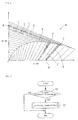
FIG. 1 is a block diagram of a brake control device in an embodiment of the present invention. -
FIG. 2 a braking force map stored by a memory of the brake control device. -
FIG. 3 is a flowchart depicting processing of the brake control device. -
FIG. 4 is a flowchart depicting processing of automatic brake control inFIG. 3 . -
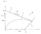
FIG. 5 is a diagram of assistance in explaining a case of increasing the braking forces of a front brake and a rear brake when it is determined that brake operation is absent inFIG. 4 . -
FIG. 6 is a diagram of assistance in explaining a first example of a case of increasing the braking forces of the front and rear brakes when it is determined that the brake operation is present inFIG. 4 . -
FIG. 7 is a diagram of assistance in explaining a second example of the case of increasing the braking forces of the front and rear brakes when it is determined that the brake operation is present inFIG. 4 . - An embodiment of the present invention will hereinafter be described with reference to the drawings.
- A
brake control device 1 according to the present embodiment is for example applied to a saddle riding type vehicle such as a motorcycle having a front wheel and a rear wheel or the like. - The
brake control device 1 has afront brake 2 and arear brake 3 that are provided independently of each other. - The
front brake 2 is configured as a hydraulic disk brake including afront brake disk 4 attached to a front wheel of the saddle riding type vehicle so as to be rotatable integrally with the front wheel and afront brake caliper 6 supplied with a hydraulic pressure (oil pressure) to clamp thefront brake disk 4. - The
rear brake 3 is configured as a hydraulic disk brake including arear brake disk 5 attached to a rear wheel of the saddle riding type vehicle so as to be rotatable integrally with the rear wheel and a rear brake caliper 7 supplied with a hydraulic pressure (oil pressure) to clamp therear brake disk 5. - The
brake control device 1 has afront master cylinder 8 and arear master cylinder 9 provided independently of each other. - The
front master cylinder 8 is coupled with a frontbrake operating element 8a such as a brake lever or the like. Thefront master cylinder 8 generates a hydraulic pressure (oil pressure) according to an operation of the frontbrake operating element 8a. - The
rear master cylinder 9 is coupled with a rearbrake operating element 9a such as a brake pedal or the like. Therear master cylinder 9 generates a hydraulic pressure (oil pressure) according to an operation of the rearbrake operating element 9a. - The
brake control device 1 has abrake modulator 10 interposed between the front andrear master cylinders rear brake calipers 6 and 7. Thebrake control device 1 constitutes a so-called by-wire type brake system that electrically links the front andrear master cylinders rear brake calipers 6 and 7. - The
brake modulator 10 includes: ahydraulic circuit unit 11 that can change a hydraulic passage and which has oil pressure generating means 11a such as a pump or the like; and an electronic control unit (ECU) 12 that controls actuation of thehydraulic circuit unit 11. - The front and
rear master cylinders rear brake calipers 6 and 7 via thehydraulic circuit unit 11. Thehydraulic circuit unit 11 at normal times blocks communication between the front andrear master cylinders rear brake calipers 6 and 7, and generates, in the oil pressure generating means 11a, an oil pressure corresponding to oil pressures generated in the front andrear master cylinders brake modulator 10 supplies the oil pressure generated by thehydraulic circuit unit 11 to the front andrear brake calipers 6 and 7 as appropriate, thereby generating braking forces in the front andrear brakes hydraulic circuit unit 11, for example, the oil pressures generated in the front andrear master cylinders rear brake calipers 6 and 7. - The
brake modulator 10 can generate braking forces in the front andrear brakes brake operating elements - The ECU 12 is supplied with detection information about amounts of operation of the front and rear
brake operating elements wheel speed sensors - The
brake modulator 10 generates an oil pressure corresponding to the amounts of operation of the front and rearbrake operating elements hydraulic circuit unit 11, and supplies the oil pressure to the front andrear brake calipers 6 and 7. Thus, thebrake modulator 10 can generate braking forces in the front andrear brakes brake operating elements - The outside recognizing means 13 includes for example a radar device installed in a front end portion of the saddle riding type vehicle. The radar device emits electromagnetic waves such as millimeter waves or the like toward the front of the vehicle in predetermined control cycles, and receives the reflected waves. The ECU 12 determines whether or not there is an obstacle in front of the vehicle (including another vehicle) on the basis of a state of transmission and reception of millimeter waves in the radar device, and when there is an obstacle, calculates a distance and a speed relative to the obstacle. The obstacle will hereinafter be referred to as a front obstacle.
- Incidentally, the outside recognizing means 13 may use a camera besides the radar device, and may be a configuration combining transmission and reception information of the radar device and imaging information of the camera.
- The ECU 12 is formed by a microcomputer including a central processing unit, a memory, and an input-output interface as hardware (only the memory is depicted by reference numeral 16). The ECU 12 performs various kinds of control processing according to detection signals of various kinds of sensors or switches and outside recognition information or the like. The ECU 12 performs anti-lock brake control (ABS control) and automatic brake control to be described later or the like by controlling actuation of the front and
rear brakes memory 16. - The
ECU 12 includes a friction coefficient estimating unit 17 that performs processing of estimating a road surface friction coefficient. The road surface friction coefficient is estimated by calculating the friction coefficient according to a difference between the wheel speeds of the front and rear wheels. Used as the difference between the wheel speeds of the front and rear wheels is for example a difference between the wheel speeds of the rear wheel as a driving wheel and the front wheel as a driven wheel, a difference between the wheel speeds of the front and rear wheels due to a momentary actuation of thebrake modulator 10, or the like. - The
memory 16 of theECU 12 stores a braking force map M for the front and rear wheels. - As depicted in
FIG. 2 , the braking force map M for example has an axis of ordinates indicating the braking force of therear brake 3 and an axis of abscissas indicating the braking force of thefront brake 2. In the braking force map M, a curve A represents an ideal increase curve of the braking forces of the front andrear brakes FIG. 2 is a front-rear braking limit point at which the saddle riding type vehicle produces a maximum deceleration by the combination of the front andrear brakes - In addition, a point B on the axis of ordinates is a rear wheel braking limit point when only the
rear brake 3 is actuated, and is a rear lock limit point indicating that increasing the rear wheel braking force to this point or more locks the rear wheel. In addition, a straight line C from the rear lock limit point B to the front-rear lock limit point Z is a rear brake limit line indicating a braking force as a lock limit of therear brake 3. - In addition, a point D on the axis of abscissas is a front wheel braking limit point when only the
front brake 2 is actuated, and is a front lock limit point indicating that increasing the front wheel braking force to this point or more locks the front wheel. In addition, a straight line E from the front lock limit point D to the front-rear lock limit point Z is a front brake limit line indicating a braking force as a lock limit of thefront brake 2. - In the braking force map M, a region F defined by the front and rear brake limit lines E and C is set as a non-lock region in which the locking of the front and rear wheels by the front and
rear brakes - A plurality of front brake limit lines E and a plurality of rear brake limit lines C are set according to the road surface friction coefficient. The front and rear brake limit lines E and C used in automatic brake control are selected according to the road surface friction coefficient estimated by the friction coefficient estimating unit 17.
- In the braking force map M, for example a small road surface friction coefficient is calculated which is at a level obtained by dividing the estimated road surface friction coefficient by a safety factor (for example 1.2 or the like). A region G defined by front and rear brake limit lines E' and C' corresponding to the small road surface friction coefficient at this level is set as a collision possibility determination region used in collision possibility determination to be described later. The front and rear brake limit lines E' and C' intersect each other at a point of intersection Z' on the curve A. The point of intersection Z' corresponds to an upper limit braking force in the collision possibility determination region G.
- The
ECU 12 includes: abrake control unit 18 performing normal brake control that actuates the front andrear brakes brake operating elements possibility determining unit 19 determining a possibility of collision of the saddle riding type vehicle with a front obstacle on the basis of the detection information of the outside recognizingmeans 13 and the front and rearwheel speed sensors operation determining unit 20 determining conditions such as the presence or absence of brake operation by the driver of the saddle riding type vehicle, amounts of the operation, and the like; and an automaticbrake control unit 21 performing automatic brake control that actuates the front andrear brakes rear brakes 2 and 3) when the collisionpossibility determining unit 19 determines that there is a possibility of collision. - Processing performed in the
ECU 12 according to the present embodiment will be described in the following with reference toFIG. 3 andFIG. 4 . This processing is performed repeatedly in predetermined control cycles. - As depicted in
FIG. 3 , first, in step S1, the collisionpossibility determining unit 19 determines the possibility of collision of the saddle riding type vehicle with a front obstacle. Specifically, the collisionpossibility determining unit 19 obtains information about the presence or absence of a front obstacle, a relative distance and a relative speed between the front obstacle and the saddle riding type vehicle, and the like on the basis of detection values of the outside recognizingmeans 13, and calculates the vehicle speed of the saddle riding type vehicle on the basis of detection values of thewheel speed sensors - Referring also to
FIG. 2 , the collisionpossibility determining unit 19 determines whether or not there is a possibility of collision with the front obstacle even when a braking force at the upper limit (for example the point of intersection Z') in the collision possibility determination region G of the braking force map M acts on the saddle riding type vehicle having the calculated vehicle speed. - When the determination in step S1 is NO (there is no possibility of collision), the present processing is directly ended. When the determination in step S1 is YES (there is a possibility of collision), the processing proceeds to step S2, where the automatic
brake control unit 21 performs automatic brake control to be described in the following. - As depicted in
FIG. 4 , the automaticbrake control unit 21 first determines the presence or absence of brake operation on the basis of detection information of brake operation detecting means not depicted in the figures which detecting means is attached to the front and rearbrake operating elements - In step S4, as automatic brake control, the automatic
brake control unit 21 first actuates only therear brake 3 to generate a rear wheel braking force. Here, when thefront brake 2 is actuated to generate a front wheel braking force as automatic brake control in the state of absence of brake operation, the saddle riding type vehicle tends to cause relatively large pitching (nose dive), which tends to lead to an unintended disturbance of the attitude of the driver. - Besides, in the present embodiment, only the
rear brake 3 is first actuated to generate a rear wheel braking force. Thus, the occurrence of pitching of the saddle riding type vehicle is suppressed, and the driver is given a feeling of deceleration. A disturbance of the attitude of the driver is therefore suppressed. - At the same time as step S4, in step S5, the automatic
brake control unit 21 reads an estimated value of the road surface friction coefficient from the friction coefficient estimating unit 17. Further, the automaticbrake control unit 21 selects limit lines according to the estimated value of the road surface friction coefficient from among the plurality of limit lines E and the plurality of limit lines C for the front andrear brakes - Thereafter, in step S6, the automatic
brake control unit 21 increases the rear wheel braking force until the rear wheel braking force reaches the selected limit line C of the rear brake 3 (see an arrow Y1 inFIG. 5 ), and determines whether or not the rear wheel braking force has increased to the selected limit line C. When the determination in step S6 is NO (the rear wheel braking force has not reached the limit line C), the present processing is ended on a temporary basis. When the determination in step S6 is YES (the rear wheel braking force has reached the limit line C), the processing proceeds to step S7, where braking is performed while thefront brake 2 is also used along the selected limit line C of therear brake 3. - In step S7, the automatic
brake control unit 21 also actuates thefront brake 2 along the limit line C of therear brake 3 in the braking force map M, that is, while maintaining the lock limit actuated state of the rear brake 3 (see an arrow Y2 inFIG. 5 ). - When the actuation of the
front brake 2 produces a front wheel braking force, the pitching of a vehicle body causes a load shift in the saddle riding type vehicle, thus decreasing the braking force as the lock limit of therear brake 3. Therefore, as the braking force of thefront brake 2 is increased, the maximum braking force of therear brake 3 is gradually decreased, but the braking force (deceleration) of the vehicle as a whole is increased, the braking force (deceleration) of the vehicle as a whole being obtained by adding together the braking forces of the front andrear brakes - Next, in step S8, the automatic
brake control unit 21 increases the braking force of thefront brake 2 until the braking forces of the front andrear brakes rear brakes rear brakes rear brakes 2 and 3). - Incidentally, the limit braking state of the front and
rear brakes - When it is determined in step S3 that the brake operation is present, on the other hand, the automatic
brake control unit 21 in step S11 reads a ratio between operations of the front andrear brakes operation determining unit 20. Specifically, the automaticbrake control unit 21 reads the front-rear operation ratio at a present brake operation position (see middle point P1 or P2 inFIG. 6 ) on the braking force map M. - In addition, at the same time as step S11, the automatic
brake control unit 21 in step S12 reads an estimated value of the road surface friction coefficient from the friction coefficient estimating unit 17. Further, the automaticbrake control unit 21 selects limit lines corresponding to the estimated value of the road surface friction coefficient from among the plurality of limit lines E and the plurality of limit lines C for the front andrear brakes - Thereafter, in step S13, the automatic
brake control unit 21 determines whether to increase the braking forces of the front andrear brakes rear brakes FIG. 6 ), or whether to make the front andrear brakes FIG. 7 ). This determination is made according to whether or not the possibility of collision with the front obstacle can be eliminated with the braking forces that maintain the ratio between the operations. The automaticbrake control unit 21 can be said to include a limit brakingnecessity determining unit 22 that makes the above-described determination. - When the determination in step S13 is NO (increase the braking forces while maintaining the ratio between the operations of the front and
rear brakes 2 and 3), in step S14, the ratio between the operations of the front andrear brakes rear brakes - By thus increasing the braking forces of the front and
rear brakes rear brakes - When the determination in step S13 is YES (increase to the limit braking force without maintaining the ratio between the operations of the front and
rear brakes 2 and 3), in step S15, the braking forces of the front andrear brakes rear brakes - The possibility of collision of the saddle riding type vehicle can be eliminated more surely by thus making the braking forces of the front and
rear brakes rear brakes - As described above, a
brake control device 1 in the foregoing embodiment includes: afront brake 2 and arear brake 3 capable of being actuated independently of each other; and abrake modulator 10 configured to control actuation of the front andrear brakes brake modulator 10 including a collisionpossibility determining unit 19 configured to determine a possibility of collision of an own vehicle with a front obstacle, an automaticbrake control unit 21 configured to perform automatic brake control that automatically increases the braking forces of the front andrear brakes possibility determining unit 19 determines that there is a possibility of collision, and a brakeoperation determining unit 20 configured to determine presence or absence of brake operation by a driver of the own vehicle, when the collisionpossibility determining unit 19 determines that there is a possibility of collision and the brakeoperation determining unit 20 determines that brake operation by the driver is absent, the automaticbrake control unit 21 first actuating only therear brake 3 to generate a rear wheel braking force, and then also actuating thefront brake 2 to generate a front wheel braking force. - According to this constitution, while automatic braking by the front and
rear brakes rear brake 3 is actuated at a time of a start of automatic braking. Thus, the pitching of the own vehicle is suppressed, and a feeling of deceleration is given to the driver. Therefore an unintended disturbance of the attitude of the driver can be suppressed. - In addition, in the
brake control device 1, when the collisionpossibility determining unit 19 determines that there is a possibility of collision, and the brakeoperation determining unit 20 determines that brake operation by the driver is absent, the automaticbrake control unit 21 first actuates only therear brake 3 to a lock limit, and then also actuates thefront brake 2 while maintaining a lock limit actuated state of therear brake 3. Thus, automatic brake control that makes the most of the braking force of therear brake 3 can be performed. - In addition, in the
brake control device 1, thebrake modulator 10 includes amemory 16 storing a braking force map M having an axis of ordinates indicating magnitude of one of the braking forces of the front andrear brakes rear brakes rear brakes brake control unit 21 actuates therear brake 3 along the limit line C of therear brake 3 in the braking force map M. Thus, automatic brake control can be performed easily by referring to the control force map M. - In addition, in the
brake control device 1, thebrake modulator 10 includes a friction coefficient estimating unit 17 configured to estimate a road surface friction coefficient, a plurality of limit lines E and a plurality of limit lines C are described according to the road surface friction coefficient, and the automaticbrake control unit 21 selects the limit line E and the limit line C according to the road surface friction coefficient. Thus, limit braking of the front andrear brakes - On the other hand, in the
brake control device 1, when the collisionpossibility determining unit 19 determines that there is a possibility of collision, and the brakeoperation determining unit 20 determines that brake operation by the driver is present, the automaticbrake control unit 21 changes a manner of increasing the braking forces of the front andrear brakes - According to this constitution, while automatic braking by the front and
rear brakes rear brakes rear brakes - In addition, in the
brake control device 1, the automaticbrake control unit 21 includes a limit brakingnecessity determining unit 22 configured to determine whether to increase the braking forces of the front andrear brakes rear brakes rear brakes necessity determining unit 22, switching can be performed between performing automatic brake control that reduces a feeling of strangeness by maintaining the ratio between the operations of the front andrear brakes rear brakes rear brakes - It is to be noted that the present invention is not limited to the foregoing embodiment. For example, there may be provided a warning device for a sense of vision, a sense of hearing, a sense of touch, and the like which warning device notifies a possibility of collision to the driver.
- The above-described saddle riding type vehicle includes vehicles in general to be ridden by a driver straddling a vehicle body. The above-described saddle riding type vehicle includes not only motorcycles (including motor-assisted bicycles and motor scooter type vehicles) but also three-wheeled vehicles (including not only vehicles having one front wheel and two rear wheels but also vehicles having two front wheels and one rear wheel) or four-wheeled vehicles.
- The constitution in the foregoing embodiment is an example of the present invention, and is susceptible of various changes, such for example as replacing constituent elements in the embodiment with well-known constituent elements, without departing from the spirit of the present invention.
-
- 1: Brake control device
- 2: Front brake
- 3: Rear brake
- 10: Brake modulator
- 16: Memory
- 17: Friction coefficient estimating unit (friction coefficient estimating means)
- 19: Collision possibility determining unit (collision possibility determining means)
- 20: Brake operation determining unit (brake operation determining means)
- 21: Automatic brake control unit (automatic brake control means)
- 22: Limit braking necessity determining unit (limit braking necessity determining means)
- M: Braking force map
- C, E: Limit line
- The present invention is directed to reduce a feeling of strangeness of a driver at a time of automatic brake control in an automatic brake device for a saddle riding type vehicle.
- A
brake modulator 10 that controls actuation of front andrear brakes possibility determining unit 19, an automaticbrake control unit 21, and a brakeoperation determining unit 20. When the collisionpossibility determining unit 19 determines that there is a possibility of collision, and the brakeoperation determining unit 20 determines that brake operation by a driver is present, the automaticbrake control unit 21 changes a manner of increasing braking forces of the front andrear brakes
Claims (4)
- An automatic brake device for a saddle riding type vehicle, the automatic brake device comprising:a front brake (2) and a rear brake (3) capable of being actuated independently of each other; anda brake modulator (10) configured to control actuation of the front and rear brakes (2, 3);the brake modulator (10) includingcollision possibility determining means (19) for determining a possibility of collision of the own vehicle with a front obstacle,automatic brake control means (21) for performing automatic brake control that automatically increases braking forces of the front and rear brakes (2, 3) when the collision possibility determining means (19) determines that there is a possibility of collision, andbrake operation determining means (20) for determining presence or absence of brake operation by a driver of the own vehicle;when the collision possibility determining means (19) determines that there is a possibility of collision, andthe brake operation determining means (20) determines that the brake operation by the driver is present,the automatic brake control means (21) changing a manner of increasing the braking forces of the front and rear brakes (2, 3) according to the brake operation by the driver.
- The automatic brake device for a saddle riding type vehicle according to claim 1, wherein
the automatic brake control means (21) includes limit braking necessity determining means (22) for determining whether to increase the braking forces of the front and rear brakes (2, 3) while maintaining a ratio between operations of the front and rear brakes (2, 3) by the driver or to make the front and rear brakes (2, 3) reach a limit braking state without maintaining the ratio between the operations. - The automatic brake device for a saddle riding type vehicle according to claim 1 or 2, wherein
the brake modulator (10) includes a memory (16) configured to store a braking force map (M) having an axis of ordinates indicating magnitude of the braking force of one of the front and rear brakes (2, 3) and having an axis of abscissas indicating magnitude of the braking force of the other of the front and rear brakes (2, 3),
a limit line (E) and a limit line (C) respectively indicating braking forces as lock limits of the front and rear brakes (2, 3) are described in the braking force map (M), and
the automatic brake control means (21) actuates the front and rear brakes (2, 3) so as to reach the limit line (E) and the limit line (C), respectively, in the braking force map (M). - The automatic brake device for a saddle riding type vehicle according to claim 3, wherein
the brake modulator (10) includes friction coefficient estimating means (17) for estimating a road surface friction coefficient,
a plurality of limit lines (E) and a plurality of limit lines (C) are described according to the road surface friction coefficient, and
the automatic brake control means (21) selects the limit line (E) and the limit line (C) according to the road surface friction coefficient.
Applications Claiming Priority (1)
| Application Number | Priority Date | Filing Date | Title |
|---|---|---|---|
| JP2015147573A JP6222746B2 (en) | 2015-07-27 | 2015-07-27 | Automatic braking system for saddle-ride type vehicles |
Publications (3)
| Publication Number | Publication Date |
|---|---|
| EP3124370A2 true EP3124370A2 (en) | 2017-02-01 |
| EP3124370A3 EP3124370A3 (en) | 2017-06-21 |
| EP3124370B1 EP3124370B1 (en) | 2019-03-20 |
Family
ID=56137176
Family Applications (1)
| Application Number | Title | Priority Date | Filing Date |
|---|---|---|---|
| EP16174969.2A Active EP3124370B1 (en) | 2015-07-27 | 2016-06-17 | Automatic brake device for saddle riding type vehicle |
Country Status (3)
| Country | Link |
|---|---|
| US (1) | US10099667B2 (en) |
| EP (1) | EP3124370B1 (en) |
| JP (1) | JP6222746B2 (en) |
Cited By (7)
| Publication number | Priority date | Publication date | Assignee | Title |
|---|---|---|---|---|
| WO2018185578A1 (en) * | 2017-04-05 | 2018-10-11 | ローベルト ボッシュ ゲゼルシャフト ミット ベシュレンクテル ハフツング | Control device, control method, and braking system |
| WO2018185577A1 (en) * | 2017-04-06 | 2018-10-11 | ローベルト ボッシュ ゲゼルシャフト ミット ベシュレンクテル ハフツング | Control device, control method, and brake system |
| WO2019037954A1 (en) * | 2017-08-22 | 2019-02-28 | Bayerische Motoren Werke Aktiengesellschaft | EMERGENCY BRAKING SYSTEM OF AN INSPECTION VEHICLE |
| WO2020254898A1 (en) * | 2019-06-19 | 2020-12-24 | ロベルト・ボッシュ・ゲゼルシャフト・ミト・ベシュレンクテル・ハフツング | Control device and control method |
| EP3734050A4 (en) * | 2017-12-28 | 2021-02-24 | Honda Motor Co., Ltd. | SADDLE VEHICLE |
| EP3967587A4 (en) * | 2019-05-10 | 2022-10-05 | Yamaha Hatsudoki Kabushiki Kaisha | TILTABLE VEHICLE EQUIPPED WITH OBSTACLE ASSISTANCE CONTROL SYSTEM |
| EP3967588A4 (en) * | 2019-05-10 | 2022-10-05 | Yamaha Hatsudoki Kabushiki Kaisha | TILT VEHICLE WITH BRAKE ASSISTANCE CONTROL DEVICE |
Families Citing this family (14)
| Publication number | Priority date | Publication date | Assignee | Title |
|---|---|---|---|---|
| JP6222746B2 (en) * | 2015-07-27 | 2017-11-01 | 本田技研工業株式会社 | Automatic braking system for saddle-ride type vehicles |
| JP6214601B2 (en) * | 2015-07-27 | 2017-10-18 | 本田技研工業株式会社 | Automatic braking system for saddle-ride type vehicles |
| US10029683B1 (en) | 2017-01-25 | 2018-07-24 | Harley-Davidson Motor Company Group, LLC | Saddle-ride vehicle with autonomous braking and method of operating same |
| JP2018134991A (en) * | 2017-02-22 | 2018-08-30 | ローベルト ボッシュ ゲゼルシャフト ミット ベシュレンクテル ハフツング | Control device, control method, and brake system |
| JP6994435B2 (en) * | 2018-06-28 | 2022-01-14 | 株式会社シマノ | Control and detection system |
| JP7270346B2 (en) * | 2018-07-24 | 2023-05-10 | ロベルト・ボッシュ・ゲゼルシャフト・ミト・ベシュレンクテル・ハフツング | Control device and control method |
| CN113631470B (en) | 2019-03-29 | 2023-02-03 | 本田技研工业株式会社 | Driving support device for saddle-ride type vehicle |
| DE112019007123B4 (en) | 2019-03-29 | 2024-05-08 | Honda Motor Co., Ltd. | DRIVING ASSISTANCE DEVICE FOR A SEMI-TYPE VEHICLE |
| EP3967586B1 (en) * | 2019-05-10 | 2023-10-04 | Yamaha Hatsudoki Kabushiki Kaisha | Leaning vehicle equipped with autonomous emergency braking (aeb) control device |
| US10780938B1 (en) | 2019-09-23 | 2020-09-22 | Lyft, Inc. | Micromobility electric vehicle ergonomics |
| JP7324671B2 (en) * | 2019-09-26 | 2023-08-10 | 日立Astemo株式会社 | Brake control device for bar-handle vehicles |
| JP7420520B2 (en) * | 2019-09-30 | 2024-01-23 | 日立Astemo株式会社 | Brake control device for bar handle vehicles |
| JP7851415B2 (en) * | 2022-11-07 | 2026-04-24 | Astemo株式会社 | Vehicle brake control system |
| JPWO2024180403A1 (en) * | 2023-02-28 | 2024-09-06 |
Citations (1)
| Publication number | Priority date | Publication date | Assignee | Title |
|---|---|---|---|---|
| JPH1114648A (en) | 1997-06-20 | 1999-01-22 | Fujitsu Ten Ltd | Vehicle speed calculation means and automatic braking device for vehicle |
Family Cites Families (18)
| Publication number | Priority date | Publication date | Assignee | Title |
|---|---|---|---|---|
| JP4345339B2 (en) * | 2003-04-09 | 2009-10-14 | 株式会社デンソー | Braking control device |
| JP4429762B2 (en) * | 2004-02-24 | 2010-03-10 | 本田技研工業株式会社 | Brake equipment for motorcycles |
| JP2006081343A (en) * | 2004-09-10 | 2006-03-23 | Nissan Motor Co Ltd | Vehicle regenerative braking control device |
| DE102004051119A1 (en) * | 2004-10-20 | 2006-04-27 | Bayerische Motoren Werke Ag | Integral brake for a motorcycle |
| JP4687220B2 (en) * | 2005-04-21 | 2011-05-25 | 株式会社アドヴィックス | Brake control device for vehicle |
| JP2008230295A (en) * | 2007-03-16 | 2008-10-02 | Suzuki Motor Corp | Braking force control device for vehicle |
| JP2008298228A (en) * | 2007-06-01 | 2008-12-11 | Jtekt Corp | Ball bearing cage |
| JP2009051241A (en) * | 2007-08-23 | 2009-03-12 | Mitsubishi Fuso Truck & Bus Corp | Automatic brake control device of vehicle |
| CN102143869B (en) * | 2008-11-25 | 2014-07-16 | 丰田自动车株式会社 | vehicle ride control |
| DE102011076633A1 (en) * | 2010-09-14 | 2012-03-15 | Robert Bosch Gmbh | Slope-dependent adaptation of a brake force control in single-track vehicles |
| KR101405754B1 (en) * | 2012-09-07 | 2014-06-10 | 성균관대학교산학협력단 | Method for controlling braking of vehicle |
| WO2014058297A1 (en) * | 2012-10-09 | 2014-04-17 | Chong Woi Joon | An automatic vehicle braking system and a control method |
| JP6042706B2 (en) * | 2012-11-21 | 2016-12-14 | 日立オートモティブシステムズ株式会社 | Vehicle control device |
| CN105142995B (en) * | 2013-04-23 | 2017-08-25 | 丰田自动车株式会社 | Speed controller |
| US9988027B2 (en) * | 2013-10-31 | 2018-06-05 | Yamaha Hatsudoki Kabushiki Kaisha | Brake system and vehicle |
| JP6222746B2 (en) * | 2015-07-27 | 2017-11-01 | 本田技研工業株式会社 | Automatic braking system for saddle-ride type vehicles |
| US9580009B1 (en) * | 2015-12-04 | 2017-02-28 | Karl Lenker | Systems and methods for motorbike collision avoidance |
| US9701307B1 (en) * | 2016-04-11 | 2017-07-11 | David E. Newman | Systems and methods for hazard mitigation |
-
2015
- 2015-07-27 JP JP2015147573A patent/JP6222746B2/en active Active
-
2016
- 2016-06-17 EP EP16174969.2A patent/EP3124370B1/en active Active
- 2016-07-19 US US15/213,833 patent/US10099667B2/en active Active
Patent Citations (1)
| Publication number | Priority date | Publication date | Assignee | Title |
|---|---|---|---|---|
| JPH1114648A (en) | 1997-06-20 | 1999-01-22 | Fujitsu Ten Ltd | Vehicle speed calculation means and automatic braking device for vehicle |
Cited By (15)
| Publication number | Priority date | Publication date | Assignee | Title |
|---|---|---|---|---|
| EP3733467A1 (en) * | 2017-04-05 | 2020-11-04 | Robert Bosch GmbH | Control device, control method, and braking system |
| WO2018185578A1 (en) * | 2017-04-05 | 2018-10-11 | ローベルト ボッシュ ゲゼルシャフト ミット ベシュレンクテル ハフツング | Control device, control method, and braking system |
| US11273807B2 (en) | 2017-04-05 | 2022-03-15 | Robert Bosch Gmbh | Controller, control method, and brake system |
| EP3730362A1 (en) * | 2017-04-05 | 2020-10-28 | Robert Bosch GmbH | Control device, control method, and braking system |
| WO2018185577A1 (en) * | 2017-04-06 | 2018-10-11 | ローベルト ボッシュ ゲゼルシャフト ミット ベシュレンクテル ハフツング | Control device, control method, and brake system |
| CN110770100B (en) * | 2017-08-22 | 2022-06-28 | 宝马股份公司 | Emergency braking system for single-rut vehicles |
| CN110770100A (en) * | 2017-08-22 | 2020-02-07 | 宝马股份公司 | Emergency braking system for single-rut vehicles |
| WO2019037954A1 (en) * | 2017-08-22 | 2019-02-28 | Bayerische Motoren Werke Aktiengesellschaft | EMERGENCY BRAKING SYSTEM OF AN INSPECTION VEHICLE |
| US11731595B2 (en) | 2017-08-22 | 2023-08-22 | Bayerische Motoren Werke Aktiengesellschaft | Emergency braking system of a single-track vehicle |
| EP3734050A4 (en) * | 2017-12-28 | 2021-02-24 | Honda Motor Co., Ltd. | SADDLE VEHICLE |
| EP3967587A4 (en) * | 2019-05-10 | 2022-10-05 | Yamaha Hatsudoki Kabushiki Kaisha | TILTABLE VEHICLE EQUIPPED WITH OBSTACLE ASSISTANCE CONTROL SYSTEM |
| EP3967588A4 (en) * | 2019-05-10 | 2022-10-05 | Yamaha Hatsudoki Kabushiki Kaisha | TILT VEHICLE WITH BRAKE ASSISTANCE CONTROL DEVICE |
| WO2020254898A1 (en) * | 2019-06-19 | 2020-12-24 | ロベルト・ボッシュ・ゲゼルシャフト・ミト・ベシュレンクテル・ハフツング | Control device and control method |
| EP4137372A1 (en) * | 2019-06-19 | 2023-02-22 | Robert Bosch GmbH | Controller and control method |
| US11780412B2 (en) | 2019-06-19 | 2023-10-10 | Robert Bosch Gmbh | Controller and control method |
Also Published As
| Publication number | Publication date |
|---|---|
| EP3124370A3 (en) | 2017-06-21 |
| EP3124370B1 (en) | 2019-03-20 |
| US20170028972A1 (en) | 2017-02-02 |
| JP6222746B2 (en) | 2017-11-01 |
| US10099667B2 (en) | 2018-10-16 |
| JP2017024645A (en) | 2017-02-02 |
Similar Documents
| Publication | Publication Date | Title |
|---|---|---|
| EP3124370B1 (en) | Automatic brake device for saddle riding type vehicle | |
| US10086808B2 (en) | Automatic brake device for saddle riding type vehicle | |
| EP3680137B1 (en) | Brake device for saddle-type vehicles | |
| US9862415B2 (en) | Lane keeping assist apparatus | |
| EP3734050A1 (en) | Saddled vehicle | |
| JP4985373B2 (en) | Vehicle motion control device | |
| US8140236B2 (en) | Method for regulating the brake pressure in motorcycles | |
| EP2733028B1 (en) | Vehicle brake hydraulic pressure control apparatus | |
| EP2759453A1 (en) | Bar-handle vehicle brake control apparatus | |
| EP3819179B1 (en) | Controller and control method for driver-assistance system used in motorcycle, and driver-assistance system used in motorcycle | |
| EP3967587B1 (en) | Leanable vehicle equipped with rider assistance control device for obstacles | |
| US11628814B2 (en) | Controller and control method for controlling behavior of motorcycle | |
| EP4206048B1 (en) | Control device and control method comprising an emergency braking in a straddle-type vehicle | |
| JP6366480B2 (en) | Brake control device for bar handle vehicle | |
| JP4561511B2 (en) | ABS control device for motorcycle | |
| JP2007015593A (en) | Car body speed computation device | |
| CN112706730A (en) | Method and device for adjusting the braking state of a vehicle, control system and program carrier | |
| JP2010526721A (en) | Method and apparatus for managing a turning set point applied to at least one turning actuator on a rear wheel of a vehicle | |
| JP5699450B2 (en) | Vehicle motion control device | |
| JP2007302016A (en) | Brake control method and its device | |
| KR20090090066A (en) | Control Method of Vehicle Posture Control System | |
| JP2017087954A (en) | Vehicular brake control apparatus | |
| JP2011240742A5 (en) |
Legal Events
| Date | Code | Title | Description |
|---|---|---|---|
| PUAI | Public reference made under article 153(3) epc to a published international application that has entered the european phase |
Free format text: ORIGINAL CODE: 0009012 |
|
| STAA | Information on the status of an ep patent application or granted ep patent |
Free format text: STATUS: REQUEST FOR EXAMINATION WAS MADE |
|
| 17P | Request for examination filed |
Effective date: 20160617 |
|
| AK | Designated contracting states |
Kind code of ref document: A2 Designated state(s): AL AT BE BG CH CY CZ DE DK EE ES FI FR GB GR HR HU IE IS IT LI LT LU LV MC MK MT NL NO PL PT RO RS SE SI SK SM TR |
|
| AX | Request for extension of the european patent |
Extension state: BA ME |
|
| PUAL | Search report despatched |
Free format text: ORIGINAL CODE: 0009013 |
|
| AK | Designated contracting states |
Kind code of ref document: A3 Designated state(s): AL AT BE BG CH CY CZ DE DK EE ES FI FR GB GR HR HU IE IS IT LI LT LU LV MC MK MT NL NO PL PT RO RS SE SI SK SM TR |
|
| AX | Request for extension of the european patent |
Extension state: BA ME |
|
| RIC1 | Information provided on ipc code assigned before grant |
Ipc: B62L 3/08 20060101AFI20170515BHEP Ipc: B62J 99/00 20090101ALN20170515BHEP Ipc: B60W 30/08 20120101ALI20170515BHEP Ipc: B60M 7/00 20060101ALI20170515BHEP Ipc: B62K 11/00 20060101ALI20170515BHEP Ipc: B60T 8/00 20060101ALI20170515BHEP |
|
| GRAP | Despatch of communication of intention to grant a patent |
Free format text: ORIGINAL CODE: EPIDOSNIGR1 |
|
| STAA | Information on the status of an ep patent application or granted ep patent |
Free format text: STATUS: GRANT OF PATENT IS INTENDED |
|
| RIC1 | Information provided on ipc code assigned before grant |
Ipc: B60T 8/00 20060101ALI20180903BHEP Ipc: B62J 99/00 20090101ALN20180903BHEP Ipc: B62L 3/08 20060101AFI20180903BHEP Ipc: B60W 30/08 20120101ALI20180903BHEP Ipc: B60M 7/00 20060101ALI20180903BHEP Ipc: B62K 11/00 20060101ALI20180903BHEP |
|
| RIC1 | Information provided on ipc code assigned before grant |
Ipc: B60W 30/08 20120101ALI20180914BHEP Ipc: B62L 3/08 20060101AFI20180914BHEP Ipc: B60T 8/00 20060101ALI20180914BHEP Ipc: B62J 99/00 20090101ALN20180914BHEP Ipc: B60M 7/00 20060101ALI20180914BHEP Ipc: B62K 11/00 20060101ALI20180914BHEP |
|
| INTG | Intention to grant announced |
Effective date: 20181005 |
|
| GRAS | Grant fee paid |
Free format text: ORIGINAL CODE: EPIDOSNIGR3 |
|
| GRAA | (expected) grant |
Free format text: ORIGINAL CODE: 0009210 |
|
| STAA | Information on the status of an ep patent application or granted ep patent |
Free format text: STATUS: THE PATENT HAS BEEN GRANTED |
|
| AK | Designated contracting states |
Kind code of ref document: B1 Designated state(s): AL AT BE BG CH CY CZ DE DK EE ES FI FR GB GR HR HU IE IS IT LI LT LU LV MC MK MT NL NO PL PT RO RS SE SI SK SM TR |
|
| REG | Reference to a national code |
Ref country code: GB Ref legal event code: FG4D |
|
| REG | Reference to a national code |
Ref country code: CH Ref legal event code: EP |
|
| REG | Reference to a national code |
Ref country code: DE Ref legal event code: R096 Ref document number: 602016011198 Country of ref document: DE |
|
| REG | Reference to a national code |
Ref country code: AT Ref legal event code: REF Ref document number: 1110242 Country of ref document: AT Kind code of ref document: T Effective date: 20190415 |
|
| REG | Reference to a national code |
Ref country code: IE Ref legal event code: FG4D |
|
| REG | Reference to a national code |
Ref country code: NL Ref legal event code: MP Effective date: 20190320 |
|
| PG25 | Lapsed in a contracting state [announced via postgrant information from national office to epo] |
Ref country code: SE Free format text: LAPSE BECAUSE OF FAILURE TO SUBMIT A TRANSLATION OF THE DESCRIPTION OR TO PAY THE FEE WITHIN THE PRESCRIBED TIME-LIMIT Effective date: 20190320 Ref country code: LT Free format text: LAPSE BECAUSE OF FAILURE TO SUBMIT A TRANSLATION OF THE DESCRIPTION OR TO PAY THE FEE WITHIN THE PRESCRIBED TIME-LIMIT Effective date: 20190320 Ref country code: FI Free format text: LAPSE BECAUSE OF FAILURE TO SUBMIT A TRANSLATION OF THE DESCRIPTION OR TO PAY THE FEE WITHIN THE PRESCRIBED TIME-LIMIT Effective date: 20190320 Ref country code: NO Free format text: LAPSE BECAUSE OF FAILURE TO SUBMIT A TRANSLATION OF THE DESCRIPTION OR TO PAY THE FEE WITHIN THE PRESCRIBED TIME-LIMIT Effective date: 20190620 |
|
| REG | Reference to a national code |
Ref country code: LT Ref legal event code: MG4D |
|
| PG25 | Lapsed in a contracting state [announced via postgrant information from national office to epo] |
Ref country code: BG Free format text: LAPSE BECAUSE OF FAILURE TO SUBMIT A TRANSLATION OF THE DESCRIPTION OR TO PAY THE FEE WITHIN THE PRESCRIBED TIME-LIMIT Effective date: 20190620 Ref country code: LV Free format text: LAPSE BECAUSE OF FAILURE TO SUBMIT A TRANSLATION OF THE DESCRIPTION OR TO PAY THE FEE WITHIN THE PRESCRIBED TIME-LIMIT Effective date: 20190320 Ref country code: RS Free format text: LAPSE BECAUSE OF FAILURE TO SUBMIT A TRANSLATION OF THE DESCRIPTION OR TO PAY THE FEE WITHIN THE PRESCRIBED TIME-LIMIT Effective date: 20190320 Ref country code: NL Free format text: LAPSE BECAUSE OF FAILURE TO SUBMIT A TRANSLATION OF THE DESCRIPTION OR TO PAY THE FEE WITHIN THE PRESCRIBED TIME-LIMIT Effective date: 20190320 Ref country code: HR Free format text: LAPSE BECAUSE OF FAILURE TO SUBMIT A TRANSLATION OF THE DESCRIPTION OR TO PAY THE FEE WITHIN THE PRESCRIBED TIME-LIMIT Effective date: 20190320 Ref country code: GR Free format text: LAPSE BECAUSE OF FAILURE TO SUBMIT A TRANSLATION OF THE DESCRIPTION OR TO PAY THE FEE WITHIN THE PRESCRIBED TIME-LIMIT Effective date: 20190621 |
|
| REG | Reference to a national code |
Ref country code: AT Ref legal event code: MK05 Ref document number: 1110242 Country of ref document: AT Kind code of ref document: T Effective date: 20190320 |
|
| PG25 | Lapsed in a contracting state [announced via postgrant information from national office to epo] |
Ref country code: CZ Free format text: LAPSE BECAUSE OF FAILURE TO SUBMIT A TRANSLATION OF THE DESCRIPTION OR TO PAY THE FEE WITHIN THE PRESCRIBED TIME-LIMIT Effective date: 20190320 Ref country code: IT Free format text: LAPSE BECAUSE OF FAILURE TO SUBMIT A TRANSLATION OF THE DESCRIPTION OR TO PAY THE FEE WITHIN THE PRESCRIBED TIME-LIMIT Effective date: 20190320 Ref country code: PT Free format text: LAPSE BECAUSE OF FAILURE TO SUBMIT A TRANSLATION OF THE DESCRIPTION OR TO PAY THE FEE WITHIN THE PRESCRIBED TIME-LIMIT Effective date: 20190720 Ref country code: AL Free format text: LAPSE BECAUSE OF FAILURE TO SUBMIT A TRANSLATION OF THE DESCRIPTION OR TO PAY THE FEE WITHIN THE PRESCRIBED TIME-LIMIT Effective date: 20190320 Ref country code: SK Free format text: LAPSE BECAUSE OF FAILURE TO SUBMIT A TRANSLATION OF THE DESCRIPTION OR TO PAY THE FEE WITHIN THE PRESCRIBED TIME-LIMIT Effective date: 20190320 Ref country code: EE Free format text: LAPSE BECAUSE OF FAILURE TO SUBMIT A TRANSLATION OF THE DESCRIPTION OR TO PAY THE FEE WITHIN THE PRESCRIBED TIME-LIMIT Effective date: 20190320 Ref country code: ES Free format text: LAPSE BECAUSE OF FAILURE TO SUBMIT A TRANSLATION OF THE DESCRIPTION OR TO PAY THE FEE WITHIN THE PRESCRIBED TIME-LIMIT Effective date: 20190320 Ref country code: RO Free format text: LAPSE BECAUSE OF FAILURE TO SUBMIT A TRANSLATION OF THE DESCRIPTION OR TO PAY THE FEE WITHIN THE PRESCRIBED TIME-LIMIT Effective date: 20190320 |
|
| PG25 | Lapsed in a contracting state [announced via postgrant information from national office to epo] |
Ref country code: SM Free format text: LAPSE BECAUSE OF FAILURE TO SUBMIT A TRANSLATION OF THE DESCRIPTION OR TO PAY THE FEE WITHIN THE PRESCRIBED TIME-LIMIT Effective date: 20190320 Ref country code: PL Free format text: LAPSE BECAUSE OF FAILURE TO SUBMIT A TRANSLATION OF THE DESCRIPTION OR TO PAY THE FEE WITHIN THE PRESCRIBED TIME-LIMIT Effective date: 20190320 |
|
| REG | Reference to a national code |
Ref country code: DE Ref legal event code: R084 Ref document number: 602016011198 Country of ref document: DE |
|
| PG25 | Lapsed in a contracting state [announced via postgrant information from national office to epo] |
Ref country code: IS Free format text: LAPSE BECAUSE OF FAILURE TO SUBMIT A TRANSLATION OF THE DESCRIPTION OR TO PAY THE FEE WITHIN THE PRESCRIBED TIME-LIMIT Effective date: 20190720 Ref country code: AT Free format text: LAPSE BECAUSE OF FAILURE TO SUBMIT A TRANSLATION OF THE DESCRIPTION OR TO PAY THE FEE WITHIN THE PRESCRIBED TIME-LIMIT Effective date: 20190320 |
|
| REG | Reference to a national code |
Ref country code: DE Ref legal event code: R097 Ref document number: 602016011198 Country of ref document: DE |
|
| PLBE | No opposition filed within time limit |
Free format text: ORIGINAL CODE: 0009261 |
|
| STAA | Information on the status of an ep patent application or granted ep patent |
Free format text: STATUS: NO OPPOSITION FILED WITHIN TIME LIMIT |
|
| PG25 | Lapsed in a contracting state [announced via postgrant information from national office to epo] |
Ref country code: MC Free format text: LAPSE BECAUSE OF FAILURE TO SUBMIT A TRANSLATION OF THE DESCRIPTION OR TO PAY THE FEE WITHIN THE PRESCRIBED TIME-LIMIT Effective date: 20190320 Ref country code: DK Free format text: LAPSE BECAUSE OF FAILURE TO SUBMIT A TRANSLATION OF THE DESCRIPTION OR TO PAY THE FEE WITHIN THE PRESCRIBED TIME-LIMIT Effective date: 20190320 |
|
| REG | Reference to a national code |
Ref country code: CH Ref legal event code: PL |
|
| 26N | No opposition filed |
Effective date: 20200102 |
|
| PG25 | Lapsed in a contracting state [announced via postgrant information from national office to epo] |
Ref country code: SI Free format text: LAPSE BECAUSE OF FAILURE TO SUBMIT A TRANSLATION OF THE DESCRIPTION OR TO PAY THE FEE WITHIN THE PRESCRIBED TIME-LIMIT Effective date: 20190320 |
|
| REG | Reference to a national code |
Ref country code: BE Ref legal event code: MM Effective date: 20190630 |
|
| PG25 | Lapsed in a contracting state [announced via postgrant information from national office to epo] |
Ref country code: TR Free format text: LAPSE BECAUSE OF FAILURE TO SUBMIT A TRANSLATION OF THE DESCRIPTION OR TO PAY THE FEE WITHIN THE PRESCRIBED TIME-LIMIT Effective date: 20190320 |
|
| PG25 | Lapsed in a contracting state [announced via postgrant information from national office to epo] |
Ref country code: IE Free format text: LAPSE BECAUSE OF NON-PAYMENT OF DUE FEES Effective date: 20190617 |
|
| PG25 | Lapsed in a contracting state [announced via postgrant information from national office to epo] |
Ref country code: LI Free format text: LAPSE BECAUSE OF NON-PAYMENT OF DUE FEES Effective date: 20190630 Ref country code: LU Free format text: LAPSE BECAUSE OF NON-PAYMENT OF DUE FEES Effective date: 20190617 Ref country code: CH Free format text: LAPSE BECAUSE OF NON-PAYMENT OF DUE FEES Effective date: 20190630 Ref country code: BE Free format text: LAPSE BECAUSE OF NON-PAYMENT OF DUE FEES Effective date: 20190630 |
|
| PG25 | Lapsed in a contracting state [announced via postgrant information from national office to epo] |
Ref country code: FR Free format text: LAPSE BECAUSE OF NON-PAYMENT OF DUE FEES Effective date: 20190630 |
|
| GBPC | Gb: european patent ceased through non-payment of renewal fee |
Effective date: 20200617 |
|
| PG25 | Lapsed in a contracting state [announced via postgrant information from national office to epo] |
Ref country code: GB Free format text: LAPSE BECAUSE OF NON-PAYMENT OF DUE FEES Effective date: 20200617 |
|
| PG25 | Lapsed in a contracting state [announced via postgrant information from national office to epo] |
Ref country code: CY Free format text: LAPSE BECAUSE OF FAILURE TO SUBMIT A TRANSLATION OF THE DESCRIPTION OR TO PAY THE FEE WITHIN THE PRESCRIBED TIME-LIMIT Effective date: 20190320 |
|
| PG25 | Lapsed in a contracting state [announced via postgrant information from national office to epo] |
Ref country code: HU Free format text: LAPSE BECAUSE OF FAILURE TO SUBMIT A TRANSLATION OF THE DESCRIPTION OR TO PAY THE FEE WITHIN THE PRESCRIBED TIME-LIMIT; INVALID AB INITIO Effective date: 20160617 Ref country code: MT Free format text: LAPSE BECAUSE OF FAILURE TO SUBMIT A TRANSLATION OF THE DESCRIPTION OR TO PAY THE FEE WITHIN THE PRESCRIBED TIME-LIMIT Effective date: 20190320 |
|
| PG25 | Lapsed in a contracting state [announced via postgrant information from national office to epo] |
Ref country code: MK Free format text: LAPSE BECAUSE OF FAILURE TO SUBMIT A TRANSLATION OF THE DESCRIPTION OR TO PAY THE FEE WITHIN THE PRESCRIBED TIME-LIMIT Effective date: 20190320 |
|
| PGFP | Annual fee paid to national office [announced via postgrant information from national office to epo] |
Ref country code: DE Payment date: 20250520 Year of fee payment: 10 |