EP3124787A1 - Commande et procede de commande d'eolienne - Google Patents
Commande et procede de commande d'eolienne Download PDFInfo
- Publication number
- EP3124787A1 EP3124787A1 EP16180524.7A EP16180524A EP3124787A1 EP 3124787 A1 EP3124787 A1 EP 3124787A1 EP 16180524 A EP16180524 A EP 16180524A EP 3124787 A1 EP3124787 A1 EP 3124787A1
- Authority
- EP
- European Patent Office
- Prior art keywords
- wind
- control
- curve
- characteristic curve
- cyclic
- Prior art date
- Legal status (The legal status is an assumption and is not a legal conclusion. Google has not performed a legal analysis and makes no representation as to the accuracy of the status listed.)
- Granted
Links
- 238000000034 method Methods 0.000 title claims abstract description 17
- 125000004122 cyclic group Chemical group 0.000 claims abstract description 74
- 238000005259 measurement Methods 0.000 claims abstract description 11
- 230000007423 decrease Effects 0.000 claims description 8
- 238000009434 installation Methods 0.000 claims description 5
- 238000012545 processing Methods 0.000 claims description 4
- 238000010008 shearing Methods 0.000 claims 1
- 230000000694 effects Effects 0.000 description 4
- SDIXRDNYIMOKSG-UHFFFAOYSA-L disodium methyl arsenate Chemical compound [Na+].[Na+].C[As]([O-])([O-])=O SDIXRDNYIMOKSG-UHFFFAOYSA-L 0.000 description 2
- 238000001914 filtration Methods 0.000 description 2
- 230000035484 reaction time Effects 0.000 description 2
- 230000000630 rising effect Effects 0.000 description 2
- 238000009825 accumulation Methods 0.000 description 1
- 230000005540 biological transmission Effects 0.000 description 1
- 238000006243 chemical reaction Methods 0.000 description 1
- 238000012937 correction Methods 0.000 description 1
- 238000013016 damping Methods 0.000 description 1
- 230000003247 decreasing effect Effects 0.000 description 1
- 230000003111 delayed effect Effects 0.000 description 1
- 238000013461 design Methods 0.000 description 1
- 238000001514 detection method Methods 0.000 description 1
- 238000011161 development Methods 0.000 description 1
- 230000004907 flux Effects 0.000 description 1
- 230000006870 function Effects 0.000 description 1
- 238000004519 manufacturing process Methods 0.000 description 1
- 230000000737 periodic effect Effects 0.000 description 1
- 230000005236 sound signal Effects 0.000 description 1
Images


Classifications
-
- F—MECHANICAL ENGINEERING; LIGHTING; HEATING; WEAPONS; BLASTING
- F03—MACHINES OR ENGINES FOR LIQUIDS; WIND, SPRING, OR WEIGHT MOTORS; PRODUCING MECHANICAL POWER OR A REACTIVE PROPULSIVE THRUST, NOT OTHERWISE PROVIDED FOR
- F03D—WIND MOTORS
- F03D7/00—Controlling wind motors
- F03D7/02—Controlling wind motors the wind motors having rotation axis substantially parallel to the air flow entering the rotor
- F03D7/022—Adjusting aerodynamic properties of the blades
- F03D7/0224—Adjusting blade pitch
-
- F—MECHANICAL ENGINEERING; LIGHTING; HEATING; WEAPONS; BLASTING
- F03—MACHINES OR ENGINES FOR LIQUIDS; WIND, SPRING, OR WEIGHT MOTORS; PRODUCING MECHANICAL POWER OR A REACTIVE PROPULSIVE THRUST, NOT OTHERWISE PROVIDED FOR
- F03D—WIND MOTORS
- F03D7/00—Controlling wind motors
- F03D7/02—Controlling wind motors the wind motors having rotation axis substantially parallel to the air flow entering the rotor
- F03D7/022—Adjusting aerodynamic properties of the blades
- F03D7/024—Adjusting aerodynamic properties of the blades of individual blades
-
- F—MECHANICAL ENGINEERING; LIGHTING; HEATING; WEAPONS; BLASTING
- F05—INDEXING SCHEMES RELATING TO ENGINES OR PUMPS IN VARIOUS SUBCLASSES OF CLASSES F01-F04
- F05B—INDEXING SCHEME RELATING TO WIND, SPRING, WEIGHT, INERTIA OR LIKE MOTORS, TO MACHINES OR ENGINES FOR LIQUIDS COVERED BY SUBCLASSES F03B, F03D AND F03G
- F05B2270/00—Control
- F05B2270/10—Purpose of the control system
- F05B2270/109—Purpose of the control system to prolong engine life
- F05B2270/1095—Purpose of the control system to prolong engine life by limiting mechanical stresses
-
- F—MECHANICAL ENGINEERING; LIGHTING; HEATING; WEAPONS; BLASTING
- F05—INDEXING SCHEMES RELATING TO ENGINES OR PUMPS IN VARIOUS SUBCLASSES OF CLASSES F01-F04
- F05B—INDEXING SCHEME RELATING TO WIND, SPRING, WEIGHT, INERTIA OR LIKE MOTORS, TO MACHINES OR ENGINES FOR LIQUIDS COVERED BY SUBCLASSES F03B, F03D AND F03G
- F05B2270/00—Control
- F05B2270/70—Type of control algorithm
- F05B2270/708—Type of control algorithm with comparison tables
-
- Y—GENERAL TAGGING OF NEW TECHNOLOGICAL DEVELOPMENTS; GENERAL TAGGING OF CROSS-SECTIONAL TECHNOLOGIES SPANNING OVER SEVERAL SECTIONS OF THE IPC; TECHNICAL SUBJECTS COVERED BY FORMER USPC CROSS-REFERENCE ART COLLECTIONS [XRACs] AND DIGESTS
- Y02—TECHNOLOGIES OR APPLICATIONS FOR MITIGATION OR ADAPTATION AGAINST CLIMATE CHANGE
- Y02E—REDUCTION OF GREENHOUSE GAS [GHG] EMISSIONS, RELATED TO ENERGY GENERATION, TRANSMISSION OR DISTRIBUTION
- Y02E10/00—Energy generation through renewable energy sources
- Y02E10/70—Wind energy
- Y02E10/72—Wind turbines with rotation axis in wind direction
Definitions
- the invention relates to a controller for a wind turbine.
- the controller is designed to process measured values and / or external specifications in order to determine control specifications for cyclic pitching of the wind turbine.
- Cyclic pitching can influence the load of a wind energy plant.
- US Pat. No. 7,281,891 B1 LIDAR-based wind readings can be used to obtain information about a wind field that will shortly impact the wind turbine, DE 10 2012 019 663 A1 .
- WO 2015 001 301 A1 WO 2010 086 631 A2 , It is not easy to establish the right relationship between wind readings and cyclic pitching.
- the invention has for its object to provide a control and a control method for a wind turbine, with which the stress of the wind turbine is reduced. Based on the cited prior art, the object is achieved with the features of the independent claims. Advantageous embodiments are specified in the subclaims.
- a characteristic of the amplitude of the cyclic pitch is stored in the control over a wind parameter.
- the characteristic curve has an extreme point from which the characteristic curve increases or decreases in both directions.
- the controller is designed to determine a control specification for the amplitude of the cyclical pitch from a measured value of the wind parameter on the basis of the characteristic curve.
- Cyclic pitching refers to a process in which the pitch angle of a rotor blade is changed during one complete revolution of the rotor at least once in a first direction and at least once in a second direction opposite thereto.
- the pitch angle may be changed during several consecutive revolutions of the rotor in the same way or in substantially the same way.
- cyclic pitching there is a zero position, starting from which the change in the pitch angle begins.
- the amplitude of the cyclic pitch denotes the largest angular difference between the actual pitch angle and the zero position that occurs during cyclic pitching.
- the angular difference between the actual pitch angle and the zero position is always counted positive, so there is no negative amplitude.
- the invention is based on the recognition that the cyclic load changes to which a wind turbine is subjected under the influence of a complex wind field during rotor circulation do not simply increase with wind speed, as one would expect, but that there are situations in which the wind turbines cyclical load changes become less strong despite rising wind strength. With the characteristic curve rising or falling from one extreme point in both directions, this knowledge is exploited in order to design the cyclic pitching in such a way that the occurring loads are reduced.
- the effect of the invention occurs in particular when the wind turbine is subjected to an oblique flow, ie the direction of the on Rotor impinging wind field is not parallel to the rotor axis, but forms an angle with the rotor axis.
- the characteristic curve is therefore assigned to one or more operating states of the wind energy plant in which the wind energy plant is exposed to an oblique flow. Assuming that the skew (ie, the angle at which the wind hits the rotor or more precisely hits the rotor axis direction) remains constant as the wind speed changes, the wind turbine is the least cyclic at medium wind speed load changes. Starting from this mean wind speed, the cyclic load changes become stronger with both increasing and decreasing wind speed.
- the characteristic curve can therefore be designed in particular such that the amplitude decreases starting from a lower wind speed until the amplitude drops to an extreme point at an average wind speed, and the amplitude rises again as the wind speed increases.
- the controller is preferably arranged to take this into account when creating the tax target.
- wind speed in the context of the invention designates the average wind speed of the wind field.
- the characteristic according to the invention can refer to a state in which the wind energy installation is subjected to shear.
- both the shear and the inclined flow are taken into account by assigning the characteristic curve to a state in which the wind turbine is exposed to both shear and oblique flow.
- Wind parameters in the context of the invention generally designate the quantities that the wind field striking the wind energy installation characterize. Wind parameters include wind strength, skew and shear.
- the shear and the slant flow are in turn characterized by two parameters, respectively, required to represent the shear or slant flow in a coordinate system. Which parameters are depends on the choice of the coordinate system. For example, it is possible to divide the oblique flow and the shear respectively into a horizontal and a vertical portion, so that a horizontal oblique flow, a vertical oblique flow as well as a horizontal shear and a vertical shear result. Each of these quantities may for example be defined as an angle relative to the axis of the rotor. Other forms of presentation are possible, for example, the shear can also be defined linearly as a change in the wind speed with respect to the distance to a reference plane.
- Preference is given to the representation of Shear uses a coordinate system that has symmetry relative to natural shear.
- the axes of the coordinate system may be inclined, so that both a portion of the horizontal shear and a portion of the vertical shear is plotted on both axes. This form of representation makes it easier to identify additional (stochastic) shears.
- the controller may make a control specification according to which the amplitude of the cyclical pitch is smaller at the average wind speed than at higher or lower wind speed.
- the characteristic curve is designed such that the other wind parameters which are not set by the characteristic curve in relation to the amplitude of the cyclical pitching are assumed to be constant.
- the characteristic changes as the angle of the oblique flow or the angle of the shear changes.
- a simplified model it is possible to assume a linear relationship between the angle of the slant flow and / or the angle of the shear and the amplitude of the cyclic pitch. With this assumption, it is possible to adapt the characteristic curve on the basis of measured values of the oblique flow or the shear by linear conversion.
- the plurality of characteristic curves can be represented in the form of a two-dimensional characteristic map or in the form of a multi-dimensional characteristic space.
- the dimension of the characteristic space can correspond to the number of wind parameters that are used to characterize the wind field.
- the characteristic space can also include characteristic curves which have no extreme point in the sense of the invention.
- the amplitude of the cyclic pitch may be plotted over a wind parameter other than the wind force.
- the characteristic curve can rise or fall in both directions, starting from the extreme point.
- the individual characteristic curve is based on the assumption that certain wind parameters remain constant, this does not apply to a real wind field without further ado. Rather, it must be assumed that all wind parameters change constantly in a real wind field. For the control according to the invention, this means that there is a constant alternation between different characteristic curves. It is possible that during a revolution of the rotor is repeatedly switched back and forth between different characteristics. For this reason, the actual pitch curve of the cyclic pitch can already have a complex course if the pitch curve derived from the individual characteristic curve is a simple sine curve.
- the cyclic pitch control specification may be configured to vary the pitch angle during one revolution of the rotor from a zero pitch angle adjustment in both the one direction and the other direction.
- the variation in one direction may be symmetrical to the variation in the other direction.
- the cyclic pitching has a sinusoidal course, wherein the period of the sine curve corresponds to a complete revolution of the rotor. Such a sinusoid can be clearly defined by amplitude and phase.
- the clear definition of the pitch curve thus results from the amplitude of the cyclic pitch and the angular position of the rotor in which the amplitude is achieved.
- a restriction on such simple curves does not make the invention.
- arbitrary curves can be defined by plotting desired values for the pitch angle over the angular position of the rotor blades.
- the cyclic pitching is preferably designed such that a plurality of rotor blades of a wind energy plant each receive their own control specification for the cyclic pitching.
- the control specifications may be such that with respect to the coordinate system of the nacelle relative to which the rotor is rotating, the pitch curves are all identical.
- the zero crossings may be at an angular position of the rotor that is defined relative to the direction of the oblique flux and / or the direction of the shear.
- the pitch curve of the cyclic pitch may be a linear superposition of a part curve associated with the skew flow and a part curve associated with the shear.
- the partial curve of the oblique flow may be symmetrical to the direction of the oblique flow.
- the partial curve of the shear may be symmetrical to the direction of shear. If a representation form with a splitting into a horizontal component and a vertical component is selected for the oblique flow and the shear, then the pitch curve can result as a superimposition of four partial curves.
- the two zero crossings of the pitch curve can take place in the angular positions of the rotor, in which the relevant rotor blade crosses the direction of the oblique incident flow.
- the oblique flow is a purely horizontal oblique flow
- the zero crossing occurs when the rotor blade is aligned horizontally.
- the rotor may have rotated 10 ° to 30 ° before the zero crossing of the cyclic pitch occurs.
- sensors may be arranged on the wind energy plant to record the wind measurement values.
- the sensors may be suspended from the nacelle and / or rotor of the wind turbine.
- Wind turbine means a device in which a generator is driven via a rotor to generate electrical energy. It is also possible to arrange sensors on a device adjacent to the wind turbine. Preferably, the sensors are arranged substantially at the same height as the rotor of the wind energy plant. Information about the wind field can also be derived from measurements obtained on a neighboring wind turbine.
- the measured values are preferably recorded in such a way that information about each of the mentioned wind parameters can be derived. From the measured values, this results in information about the mean wind speed as well as the oblique flow and the shear in two dimensions each. In the control, all wind parameters are preferably processed.
- the sensors may be designed so that they relate to the actual state of the wind field, so that wind field, which currently acts on the rotor. Additionally or alternatively, the inclusion of forward measured values is also possible for determining wind parameters to which the wind energy plant will shortly be exposed.
- the recording of forward measured values can be carried out, for example, by LIDAR and / or SODAR sensors.
- LIDAR is a shorthand for light detection on ranging and refers to a measuring method in which light pulses are emitted and in which the backscattered light from the atmosphere is detected. On the basis of the backscattered light can be concluded on the wind parameters sought.
- SODAR is a corresponding measuring method in which sound waves instead of light pulses are emitted and in which the sound signals reflected back from the atmosphere are detected.
- the transit time is preferably taken into account between the time at which the forward measured values were recorded and the time at which the wind energy installations are actually exposed to the relevant wind parameters.
- the controller is arranged so that the forward measurements are included in the cyclic pitch control timing at a time short of the time the wind turbine is actually exposed to the wind parameters according to the forward measurements.
- the reaction time of the wind turbine, the time for data processing and / or the time delay can be taken into account by filtering.
- the forward measured values should be included as soon as the wind parameters actually affect the wind turbine or the component of the wind turbine.
- the sensor for recording the forward measured values can be arranged on the wind energy plant.
- the wind turbine comprises a rotor which is connected via a rotor shaft to a generator.
- the generator is arranged inside a nacelle, which is rotatably mounted on a tower.
- the sensor for the forward measured values can be arranged on the nacelle.
- the sensor can be oriented to take readings in windward, that is, in the direction the wind is coming from. If the sensor sends out measurement signals, these can be sent against the wind direction. In this way, information about a wind field can be obtained, which will shortly act on the wind turbine.
- a single rotor blade comprises a plurality of sensors distributed over the length of the blade.
- the sensors can cover a large area.
- the sensors are preferably oriented in such a way that they record measured values in windward conditions.
- An additional or alternative possibility for obtaining measured values is the inclusion of actual values in a component of the wind energy plant. Such measurements may be used to determine a control specification for another component of the wind turbine that will be in that position at a later time.
- an actual value can be recorded on a rotor blade and the measured value used to determine a control specification for a rotor blade, which will be in the same position at a later time.
- the running time until the rotor blade is in the relevant position results from the speed of the rotor. If the rotor has, for example, three rotor blades, the running time corresponds to a rotation angle of 120 ° or a multiple thereof.
- Another additional or alternative possibility for obtaining forward measured values is the recording of actual values at a location spaced from the wind energy plant. Preferably, this location is arranged in windward, so that measured values are recorded on a wind field that will shortly hit the wind turbine.
- the measured values can, for example, be recorded on a mast that has been erected in a suitable position. It is also possible that measured values are used as forward measured values recorded on a neighboring wind turbine.
- the controller according to the invention can be designed so that it is also responsible for the operation control of the pitch angle.
- control specifications are made according to which the pitch angle is adjusted so that the correct amount of power is taken from the wind.
- the operation control usually all rotor blades of the rotor receive the same control of the pitch angle.
- the characteristic according to the invention can be used in particular in the operating range in which the wind energy plant is operated at rated power. At rated power, the pitch angle of the rotor blades is changed to keep the power constant and to limit the rotor speed.
- Today's wind turbines are often designed to operate at wind speeds between about 12 m / s and 24 m / s at rated power.
- control specification for cyclic pitching is the same for all rotor blades of the wind turbine. In the example mentioned, this means that for each of the rotor blades in an angular position of 30 ° the pitch angle is adjusted by + 3 ° and in an angular position of 210 ° by -3 °.
- the rotor blades receive different control specifications for the cyclic pitching. This can serve, for example, to compensate for an imbalance of the rotor. Imbalances can result from, among other things, ice accumulation on a rotor blade or an error in the production of the rotor blade. This correction can be done by a further linear overlay in the control specification for the cyclic pitching.
- the invention also relates to a control method for a wind energy plant, in which measured values and / or external specifications are processed in order to determine control specifications for a cyclic pitching of the wind energy plant.
- a control specification for the amplitude of the cyclic pitch is determined on the basis of a characteristic curve of the amplitude of the cyclic pitching over a wind parameter while processing a measured value of the wind parameter.
- the characteristic curve has an extreme point from which the characteristic curve increases or decreases in both directions.
- control method can be developed with further features that are described in the context of the control according to the invention.
- the control can be developed with further features, which are described in the context of the control method according to the invention.
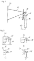
- An in Fig. 1 shown wind turbine 14 includes a rotor 15 which drives a generator arranged inside a nacelle 16.
- the electrical energy generated by the generator is conducted via a connection 17 in an electrical network.
- the nacelle 16 is rotatable relative to the tower of the wind turbine 14 so that the rotor 15 can be oriented relative to the wind.
- the nacelle 16 is aligned so that the rotor 15 points in the direction of the wind, ie after windward.
- the wind turbine 14 is equipped with a LIDAR device 18, which emits light pulses 19 in order to obtain information about a wind field 20, which moves in the direction of the rotor 15.
- the LIDAR device evaluates backscattered light signals from the atmosphere to obtain the desired information about the wind field 20.
- Fig. 2 Among the wind parameters obtained with the LIDAR device are the vertical shear 21 (FIG. Fig. 2A ), the horizontal shear 22 (FIG. Fig. 2B ), the horizontal slant flow 23 (FIG. Fig. 2C ) and the vertical slant flow 24 (FIG. Fig. 2D ). Both the shear 21, 22 and the oblique flow 23, 24 cause a periodic load change on the rotor 15, wherein the load change occurs once per revolution of the rotor. Each of these quantities represents a wind parameter within the meaning of the invention. Together with the average wind speed of the wind field 20, which is likewise determined with the LIDAR module 18, five wind parameters are taken into account in the control method.
- the controller 25 of the wind turbine 14 is based on Fig. 3 explained.
- the controller 25 comprises a control unit 26, which has measured values 27 via a first input and a second value via a first input Input specifications 28 are supplied from the outside.
- the measured values can relate, for example, to the state of the electrical system of the wind energy plant 14, the state of the electrical network or the current wind speed to which the wind energy plant 14 is exposed.
- the external requirements can for example come from a central office of the transmission network and relate to the electrical voltage with which to be fed into the network.
- the control unit 26 processes the measured values and the specifications from the outside and uses them to determine control specifications 29, which are passed to the respective actuators of the wind energy plant 14, so that the wind energy plant 14 can stop operating in accordance with the control specifications 29.
- control specification may be, for example, a setting of the generator or of the converter with which the proportion of reactive power is influenced.
- control specifications 29 includes a specification for the pitch angle of the rotor blades.
- the control unit 26 thus takes over the operation control of the wind power plant 14.
- the control 25 is operated as a closed loop in which the changes caused by the control inputs 29 are measured and used to determine new control specifications 29.
- the controller 25 is connected to the LIDAR device 18 via a line 30 and is supplied by the LIDAR device 18 with forward measured values via the wind parameters of the wind field 20.
- the wind field 20, the wind turbine 14 is not currently exposed, but the wind field 20 still has a distance of, for example, some 100 m to the wind turbine 14 and moves in the direction of the wind turbine 14.
- the wind field 20 will thus meet shortly on the rotor 15.
- the forward measured values from the LIDAR unit do not concern the current operating state of the wind turbine 14, but a future operating state.
- the forward measured values are processed in a computing unit 31 in order to determine a control parameter for the cyclic pitching.
- the wind parameters are first calculated from the pure LIDAR measurement data and then the control specification for the cyclic pitching is determined.
- the purpose of cyclic pitching is to reduce the stress caused by the cyclic load changes resulting from the skew and shear. The pitch angle of a rotor blade is thus changed during a revolution of the rotor so that the cyclic load changes is counteracted.
- the control computer 31 determines a first part curve, which is intended to counteract the vertical shear 21.
- the control computer 31 determines a second partial curve, which is intended to counteract the horizontal shear 22.
- the control computer 31 determines a third partial curve, which is intended to counteract the horizontal oblique flow 23.
- the control computer 31 determines a fourth partial curve, which is intended to counteract the vertical oblique flow 24.
- Each sub-curve defines a progression for the pitch angle during one revolution of the rotor.
- the pitch curve of the cyclic pitch is obtained from the four sub-curves by linear superposition.
- the pitch curve refers to a current state of the wind field. If the wind measurement values change, this can result in a changed pitch curve, which in practice may mean that the pitch curve is constantly being adjusted.
- the curves are sinusoidal in this embodiment. So they start in a certain angular position of the rotor blade in a zero position of the cyclic pitch.
- the zero position corresponds to the control angle 29 for the pitch angle which the control unit 26 determines in the context of the normal operating control, in particular the power and speed control, on the basis of the measured values 27 and the specifications 28.
- the pitch angle is first changed in one direction in the course of one revolution of the rotor, then passes through the zero position and is changed in the other direction until the pitch angle returns to the starting point after one complete revolution of the rotor.
- the superposition of the four sub-curves results in an overall cyclic pitch curve that reduces as much as possible both the shear stress and the oblique flow stress.
- the total curve is passed to a runtime module 32.
- the transit time module 32 processes the measured value obtained from the LIDAR unit 18 over the average wind speed of the wind field 20 and determines therefrom a point in time at which the wind field 20 is expected to hit the rotor 15. Taking into account the reaction time of the wind turbine 14 as well as the time for the data processing and the delay by the necessary filtering, the runtime module 32 derives the overall curve shortly before the arrival of the wind field 20 to the control unit 26.
- the control unit 26 superimposed on the overall curve by means of a pilot control above the normal control of the pitch angle. This control specification is implemented by the wind turbine 14 just at the time when the wind field 20 hits the rotor 15.
- the control computer 31 uses a characteristic curve 33, as exemplified in FIG Fig. 4 is shown.
- the wind speed V is plotted in meters per second.
- the amplitude of the cyclic pitch is plotted on the vertical axis, ie the maximum deflection of the pitch angle with respect to the central position, which the pitch angle achieves during the cyclic pitching.
- the amplitude drops to zero at a wind velocity V of about 16 m / s.
- the Characteristic curve 33 thus has an extreme point 39 in the sense of the invention.
- the characteristic 33 is associated with a certain angle of the horizontal oblique flow.
- the control computer 31 uses an alternative characteristic curve.
- the alternative characteristic curve can result from the assumption of a linear relationship between the amplitude and the wind parameter and the characteristic curve being converted accordingly.
- Fig. 4 only shows the characteristic curve for a selected example.
- the axis scales and the sign convention, a significantly different course of the characteristic, for example, a maximum instead of a minimum result in the middle characteristic part.
- the characteristic curve range can also be extended to significantly lower wind speeds (lower part-load operation) or significantly higher wind speeds (upper part-load operation).
- the control computer 31 selects from its memory the suitable characteristic 33 from a multiplicity of stored characteristic curves or the control computer 31 computationally determines a suitable characteristic from a characteristic stored in the memory .
- a value for the amplitude of the cyclic pitch can be read from the characteristic curve 33.
- the phase of the cyclic pitch is determined relative to the direction of the horizontal slant flow 23. Thereafter, the zero crossing of the cyclic pitch takes place where the rotor blade crosses the direction of the oblique flow, that is, where the rotor blade is also aligned horizontally.
- the cyclic pitch curve is a sinusoid that is already largely determined by the two parameters amplitude and phase.
- the only missing information is the direction in which the pitch angle is based on the relevant Zero crossing is deflected.
- the additional information is stored in the memory of the control computer 31, that takes place at a wind speed V of 16 m / s, a phase reversal.
- V of 16 m / s the pitch angle is deflected from the respective zero crossing in one direction.
- the pitch angle is deflected from the respective zero crossing in the other direction.
- the sine curve for the horizontal slant flow 23 is uniquely determined.
- Corresponding curves for the cyclic pitch are determined for the vertical slant flow 24, the vertical shear 21 and the horizontal shear 22. A linear superposition of the four curves gives a total curve for the cyclic pitching.
- other curves for cyclic pitching can be overlaid linearly or nonlinearly, for example a functionality for damping lateral transverse vibrations of the tower.
- the characteristic in Fig. 4 essentially covers the range of wind strength V in which the wind turbine 14 can be operated at rated power. From the in Fig. 4 shown characteristic curve 33 shows that at the relatively low wind speed V of 12 m / s, the amplitude of the cyclic pitch is large. At a wind velocity V of about 16 m / s, the amplitude of the cyclic pitch decreases to zero. The pitch angle then remains fixed in its predetermined by the operation control zero position. As the wind speed V continues to increase, the amplitude of the cyclic pitch increases again, the phase position now being exactly the opposite, ie shifted by 180 °.
- FIG Fig. 5 Various possibilities for pitch curves, which are determined by the control computer 31 in this way, are shown in FIG Fig. 5 shown.
- the pitch curve 34 refers to a wind speed V of 12 m / s
- the pitch curve 35 refers to a wind speed V of 16 m / s
- the pitch curve 36 refers to a wind speed V of 20 m / s
- the pitch curve 37 refers to a wind speed V of 24 m / s.
- the pitch curves 34 to 37 also illustrate the different amplitudes as a function of the wind speed V and the phase reversal at a wind speed V of about 16 m / s.
- the pitch curve 34 has a slightly shifted phase position.
- the zero crossing of the pitch curve 34 does not take place in an angular position of the rotor blade of 90 °, but somewhat delayed at about 110 °. It has been found that this slightly shifted rearward phase position of the cyclic pitch at a wind speed of 12 m / s is best suited to keep the load of the wind turbine 14 low.
Landscapes
- Engineering & Computer Science (AREA)
- Physics & Mathematics (AREA)
- Fluid Mechanics (AREA)
- Life Sciences & Earth Sciences (AREA)
- Sustainable Development (AREA)
- Sustainable Energy (AREA)
- Chemical & Material Sciences (AREA)
- Combustion & Propulsion (AREA)
- Mechanical Engineering (AREA)
- General Engineering & Computer Science (AREA)
- Wind Motors (AREA)
Applications Claiming Priority (1)
| Application Number | Priority Date | Filing Date | Title |
|---|---|---|---|
| DE102015009704.0A DE102015009704A1 (de) | 2015-07-30 | 2015-07-30 | Steuerung und Steuerungsverfahren für eine Windenergieanlage |
Publications (2)
| Publication Number | Publication Date |
|---|---|
| EP3124787A1 true EP3124787A1 (fr) | 2017-02-01 |
| EP3124787B1 EP3124787B1 (fr) | 2020-09-02 |
Family
ID=56497682
Family Applications (1)
| Application Number | Title | Priority Date | Filing Date |
|---|---|---|---|
| EP16180524.7A Not-in-force EP3124787B1 (fr) | 2015-07-30 | 2016-07-21 | Commande et procede de commande d'eolienne |
Country Status (4)
| Country | Link |
|---|---|
| EP (1) | EP3124787B1 (fr) |
| DE (1) | DE102015009704A1 (fr) |
| DK (1) | DK3124787T3 (fr) |
| ES (1) | ES2833418T3 (fr) |
Cited By (2)
| Publication number | Priority date | Publication date | Assignee | Title |
|---|---|---|---|---|
| CN113606086A (zh) * | 2021-08-31 | 2021-11-05 | 中国科学院工程热物理研究所 | 一种风电机组周期性变桨控制装置及方法 |
| CN115478984A (zh) * | 2022-08-04 | 2022-12-16 | 明阳智慧能源集团股份公司 | 衰减风电机组塔筒前后方向二阶振动与载荷的方法与系统 |
Families Citing this family (1)
| Publication number | Priority date | Publication date | Assignee | Title |
|---|---|---|---|---|
| CN111551960B (zh) * | 2020-05-20 | 2022-06-03 | 西安理工大学 | 风速测量方法及装置 |
Citations (6)
| Publication number | Priority date | Publication date | Assignee | Title |
|---|---|---|---|---|
| DE102005034899A1 (de) * | 2005-07-26 | 2007-02-01 | Repower Systems Ag | Windenergieanlage mit Einzelpitcheinrichtungen |
| US7281891B2 (en) | 2003-02-28 | 2007-10-16 | Qinetiq Limited | Wind turbine control having a lidar wind speed measurement apparatus |
| WO2010086631A2 (fr) | 2009-02-02 | 2010-08-05 | Vestas Wind Systems A/S | Système et procédé de commande destinés à une éolienne |
| EP2500562A2 (fr) * | 2011-03-17 | 2012-09-19 | Gamesa Innovation & Technology, S.L. | Procédés et systèmes pour atténuer les charges générées dans les éoliennes par asymétries du vent |
| DE102012019663A1 (de) | 2012-10-08 | 2014-04-10 | Robert Bosch Gmbh | Vorrichtung und Verfahren zur Bestimmung von Windfeldparametern und Windenergieanlage |
| WO2015001301A1 (fr) | 2013-06-30 | 2015-01-08 | Wind Farm Analytics Ltd | Mesure sur le terrain de la vitesse d'un fluide de turbine |
Family Cites Families (1)
| Publication number | Priority date | Publication date | Assignee | Title |
|---|---|---|---|---|
| DE29715249U1 (de) * | 1997-08-25 | 1998-12-24 | Institut für Solare Energieversorgungstechnik Verein an der Universität Gesamthochschule Kassel eV, 34119 Kassel | Windenergieanlage |
-
2015
- 2015-07-30 DE DE102015009704.0A patent/DE102015009704A1/de not_active Withdrawn
-
2016
- 2016-07-21 EP EP16180524.7A patent/EP3124787B1/fr not_active Not-in-force
- 2016-07-21 ES ES16180524T patent/ES2833418T3/es active Active
- 2016-07-21 DK DK16180524.7T patent/DK3124787T3/da active
Patent Citations (6)
| Publication number | Priority date | Publication date | Assignee | Title |
|---|---|---|---|---|
| US7281891B2 (en) | 2003-02-28 | 2007-10-16 | Qinetiq Limited | Wind turbine control having a lidar wind speed measurement apparatus |
| DE102005034899A1 (de) * | 2005-07-26 | 2007-02-01 | Repower Systems Ag | Windenergieanlage mit Einzelpitcheinrichtungen |
| WO2010086631A2 (fr) | 2009-02-02 | 2010-08-05 | Vestas Wind Systems A/S | Système et procédé de commande destinés à une éolienne |
| EP2500562A2 (fr) * | 2011-03-17 | 2012-09-19 | Gamesa Innovation & Technology, S.L. | Procédés et systèmes pour atténuer les charges générées dans les éoliennes par asymétries du vent |
| DE102012019663A1 (de) | 2012-10-08 | 2014-04-10 | Robert Bosch Gmbh | Vorrichtung und Verfahren zur Bestimmung von Windfeldparametern und Windenergieanlage |
| WO2015001301A1 (fr) | 2013-06-30 | 2015-01-08 | Wind Farm Analytics Ltd | Mesure sur le terrain de la vitesse d'un fluide de turbine |
Non-Patent Citations (1)
| Title |
|---|
| TORBEN JUUL LARSEN ET AL: "Active load reduction using individual pitch, based on local blade flow measurements", WIND ENERGY, WILEY, CHICHESTER, GB, vol. 8, no. 1, 16 December 2004 (2004-12-16), pages 67 - 80, XP002504578, ISSN: 1099-1824, DOI: 10.1002/WE.141 * |
Cited By (2)
| Publication number | Priority date | Publication date | Assignee | Title |
|---|---|---|---|---|
| CN113606086A (zh) * | 2021-08-31 | 2021-11-05 | 中国科学院工程热物理研究所 | 一种风电机组周期性变桨控制装置及方法 |
| CN115478984A (zh) * | 2022-08-04 | 2022-12-16 | 明阳智慧能源集团股份公司 | 衰减风电机组塔筒前后方向二阶振动与载荷的方法与系统 |
Also Published As
| Publication number | Publication date |
|---|---|
| DK3124787T3 (da) | 2020-11-23 |
| DE102015009704A1 (de) | 2017-02-02 |
| ES2833418T3 (es) | 2021-06-15 |
| EP3124787B1 (fr) | 2020-09-02 |
Similar Documents
| Publication | Publication Date | Title |
|---|---|---|
| DE102004051843B4 (de) | Windenergieanlage und Verfahren zur automatischen Korrektur von Windfahnenfehleinstellungen | |
| EP2861867B1 (fr) | Éolienne et procédé de commande d'une éolienne ou d'un parc éolien | |
| EP2225461B1 (fr) | Procédé permettant de faire fontionner une éolienne | |
| EP3542056B1 (fr) | Procédé pour commander une éolienne et éolienne correspondante | |
| WO2018162706A1 (fr) | Procédé servant à définir une puissance disponible d'un parc éolien et parc éolien associé | |
| EP3420226B1 (fr) | Procédé pour déterminer une vitesse du vent équivalente | |
| DE102010017777A1 (de) | Verfahren und Vorrichtung zum Steuern der Umfangsgeschwindigkeit an Rotorflügelspitzen | |
| DE102010023887A1 (de) | Verfahren und Vorrichtung zur Verhinderung einer Querschwingung einer Windenergieanlage | |
| EP3527816B1 (fr) | Procédé et système de détermination d'une fonction de correction d'alignement | |
| EP3473852B1 (fr) | Système de commande et procédé de fonctionnement d'un pluralité d'éoliennes | |
| WO2013034235A1 (fr) | Procédé et dispositif pour déterminer une erreur d'angle de lacet d'une éolienne, et éolienne correspondante | |
| EP2366895B1 (fr) | Procédé de détermination d'un angle d'azimut pendant une activité de maintenance d'éolienne | |
| WO2019197680A1 (fr) | Éolienne, parc éolien et procédé de réglage d'une éolienne et d'un parc éolien | |
| EP3298272A1 (fr) | Dispositif de mesure situé sur une éolienne | |
| EP3124787B1 (fr) | Commande et procede de commande d'eolienne | |
| EP3715626B1 (fr) | Procédé de détermination d'une courbe de performance d'une éolienne et éolienne correspondante | |
| EP4227523B1 (fr) | Procédé de fonctionnement d'un parc éolien, éolienne et parc éolien | |
| DE102009015679A1 (de) | Stationäre Energiegewinnungsanlage mit Steuereinrichtung und Verfahren zur Steuerung der Energiegewinnungsanalge | |
| EP2226501B1 (fr) | Procédé et arrangement permettant de mesurer une éolienne | |
| EP3983674B1 (fr) | Procédé permettant de détecter la vitesse du vent, procédé permettant de commander une éolienne, procédé permettant de commander un parc éolien; et éolienne | |
| DE102018113706A1 (de) | Verfahren zum Betreiben einer Windenergieanlage, Windenergieanlage und Windpark | |
| DE102012024272A1 (de) | Verfahren und Vorrichtung zum Verringern eines Rotors einer Windenergieanlage belastenden Nickmoments | |
| EP3500752B1 (fr) | Système de mesure d'une éolienne | |
| WO2020115018A1 (fr) | Procédé pour faire fonctionner une éolienne | |
| EP4012174B1 (fr) | Procédé et dispositif de fonctionnement d'une éolienne |
Legal Events
| Date | Code | Title | Description |
|---|---|---|---|
| PUAI | Public reference made under article 153(3) epc to a published international application that has entered the european phase |
Free format text: ORIGINAL CODE: 0009012 |
|
| STAA | Information on the status of an ep patent application or granted ep patent |
Free format text: STATUS: THE APPLICATION HAS BEEN PUBLISHED |
|
| AK | Designated contracting states |
Kind code of ref document: A1 Designated state(s): AL AT BE BG CH CY CZ DE DK EE ES FI FR GB GR HR HU IE IS IT LI LT LU LV MC MK MT NL NO PL PT RO RS SE SI SK SM TR |
|
| AX | Request for extension of the european patent |
Extension state: BA ME |
|
| STAA | Information on the status of an ep patent application or granted ep patent |
Free format text: STATUS: REQUEST FOR EXAMINATION WAS MADE |
|
| 17P | Request for examination filed |
Effective date: 20170801 |
|
| RBV | Designated contracting states (corrected) |
Designated state(s): AL AT BE BG CH CY CZ DE DK EE ES FI FR GB GR HR HU IE IS IT LI LT LU LV MC MK MT NL NO PL PT RO RS SE SI SK SM TR |
|
| GRAP | Despatch of communication of intention to grant a patent |
Free format text: ORIGINAL CODE: EPIDOSNIGR1 |
|
| STAA | Information on the status of an ep patent application or granted ep patent |
Free format text: STATUS: GRANT OF PATENT IS INTENDED |
|
| INTG | Intention to grant announced |
Effective date: 20200407 |
|
| GRAS | Grant fee paid |
Free format text: ORIGINAL CODE: EPIDOSNIGR3 |
|
| GRAA | (expected) grant |
Free format text: ORIGINAL CODE: 0009210 |
|
| STAA | Information on the status of an ep patent application or granted ep patent |
Free format text: STATUS: THE PATENT HAS BEEN GRANTED |
|
| AK | Designated contracting states |
Kind code of ref document: B1 Designated state(s): AL AT BE BG CH CY CZ DE DK EE ES FI FR GB GR HR HU IE IS IT LI LT LU LV MC MK MT NL NO PL PT RO RS SE SI SK SM TR |
|
| REG | Reference to a national code |
Ref country code: GB Ref legal event code: FG4D Free format text: NOT ENGLISH |
|
| REG | Reference to a national code |
Ref country code: AT Ref legal event code: REF Ref document number: 1309096 Country of ref document: AT Kind code of ref document: T Effective date: 20200915 Ref country code: CH Ref legal event code: EP |
|
| REG | Reference to a national code |
Ref country code: DE Ref legal event code: R096 Ref document number: 502016010997 Country of ref document: DE |
|
| REG | Reference to a national code |
Ref country code: IE Ref legal event code: FG4D Free format text: LANGUAGE OF EP DOCUMENT: GERMAN |
|
| REG | Reference to a national code |
Ref country code: DK Ref legal event code: T3 Effective date: 20201119 |
|
| RAP2 | Party data changed (patent owner data changed or rights of a patent transferred) |
Owner name: SIEMENS GAMESA RENEWABLE ENERGY SERVICE GMBH |
|
| REG | Reference to a national code |
Ref country code: LT Ref legal event code: MG4D |
|
| PG25 | Lapsed in a contracting state [announced via postgrant information from national office to epo] |
Ref country code: GR Free format text: LAPSE BECAUSE OF FAILURE TO SUBMIT A TRANSLATION OF THE DESCRIPTION OR TO PAY THE FEE WITHIN THE PRESCRIBED TIME-LIMIT Effective date: 20201203 Ref country code: NO Free format text: LAPSE BECAUSE OF FAILURE TO SUBMIT A TRANSLATION OF THE DESCRIPTION OR TO PAY THE FEE WITHIN THE PRESCRIBED TIME-LIMIT Effective date: 20201202 Ref country code: SE Free format text: LAPSE BECAUSE OF FAILURE TO SUBMIT A TRANSLATION OF THE DESCRIPTION OR TO PAY THE FEE WITHIN THE PRESCRIBED TIME-LIMIT Effective date: 20200902 Ref country code: FI Free format text: LAPSE BECAUSE OF FAILURE TO SUBMIT A TRANSLATION OF THE DESCRIPTION OR TO PAY THE FEE WITHIN THE PRESCRIBED TIME-LIMIT Effective date: 20200902 Ref country code: HR Free format text: LAPSE BECAUSE OF FAILURE TO SUBMIT A TRANSLATION OF THE DESCRIPTION OR TO PAY THE FEE WITHIN THE PRESCRIBED TIME-LIMIT Effective date: 20200902 Ref country code: BG Free format text: LAPSE BECAUSE OF FAILURE TO SUBMIT A TRANSLATION OF THE DESCRIPTION OR TO PAY THE FEE WITHIN THE PRESCRIBED TIME-LIMIT Effective date: 20201202 Ref country code: LT Free format text: LAPSE BECAUSE OF FAILURE TO SUBMIT A TRANSLATION OF THE DESCRIPTION OR TO PAY THE FEE WITHIN THE PRESCRIBED TIME-LIMIT Effective date: 20200902 |
|
| REG | Reference to a national code |
Ref country code: NL Ref legal event code: MP Effective date: 20200902 |
|
| PG25 | Lapsed in a contracting state [announced via postgrant information from national office to epo] |
Ref country code: PL Free format text: LAPSE BECAUSE OF FAILURE TO SUBMIT A TRANSLATION OF THE DESCRIPTION OR TO PAY THE FEE WITHIN THE PRESCRIBED TIME-LIMIT Effective date: 20200902 Ref country code: LV Free format text: LAPSE BECAUSE OF FAILURE TO SUBMIT A TRANSLATION OF THE DESCRIPTION OR TO PAY THE FEE WITHIN THE PRESCRIBED TIME-LIMIT Effective date: 20200902 Ref country code: RS Free format text: LAPSE BECAUSE OF FAILURE TO SUBMIT A TRANSLATION OF THE DESCRIPTION OR TO PAY THE FEE WITHIN THE PRESCRIBED TIME-LIMIT Effective date: 20200902 |
|
| PG25 | Lapsed in a contracting state [announced via postgrant information from national office to epo] |
Ref country code: EE Free format text: LAPSE BECAUSE OF FAILURE TO SUBMIT A TRANSLATION OF THE DESCRIPTION OR TO PAY THE FEE WITHIN THE PRESCRIBED TIME-LIMIT Effective date: 20200902 Ref country code: NL Free format text: LAPSE BECAUSE OF FAILURE TO SUBMIT A TRANSLATION OF THE DESCRIPTION OR TO PAY THE FEE WITHIN THE PRESCRIBED TIME-LIMIT Effective date: 20200902 Ref country code: CZ Free format text: LAPSE BECAUSE OF FAILURE TO SUBMIT A TRANSLATION OF THE DESCRIPTION OR TO PAY THE FEE WITHIN THE PRESCRIBED TIME-LIMIT Effective date: 20200902 Ref country code: RO Free format text: LAPSE BECAUSE OF FAILURE TO SUBMIT A TRANSLATION OF THE DESCRIPTION OR TO PAY THE FEE WITHIN THE PRESCRIBED TIME-LIMIT Effective date: 20200902 Ref country code: PT Free format text: LAPSE BECAUSE OF FAILURE TO SUBMIT A TRANSLATION OF THE DESCRIPTION OR TO PAY THE FEE WITHIN THE PRESCRIBED TIME-LIMIT Effective date: 20210104 Ref country code: SM Free format text: LAPSE BECAUSE OF FAILURE TO SUBMIT A TRANSLATION OF THE DESCRIPTION OR TO PAY THE FEE WITHIN THE PRESCRIBED TIME-LIMIT Effective date: 20200902 |
|
| PG25 | Lapsed in a contracting state [announced via postgrant information from national office to epo] |
Ref country code: AL Free format text: LAPSE BECAUSE OF FAILURE TO SUBMIT A TRANSLATION OF THE DESCRIPTION OR TO PAY THE FEE WITHIN THE PRESCRIBED TIME-LIMIT Effective date: 20200902 Ref country code: IS Free format text: LAPSE BECAUSE OF FAILURE TO SUBMIT A TRANSLATION OF THE DESCRIPTION OR TO PAY THE FEE WITHIN THE PRESCRIBED TIME-LIMIT Effective date: 20210102 |
|
| REG | Reference to a national code |
Ref country code: DE Ref legal event code: R097 Ref document number: 502016010997 Country of ref document: DE |
|
| REG | Reference to a national code |
Ref country code: ES Ref legal event code: FG2A Ref document number: 2833418 Country of ref document: ES Kind code of ref document: T3 Effective date: 20210615 |
|
| PG25 | Lapsed in a contracting state [announced via postgrant information from national office to epo] |
Ref country code: SK Free format text: LAPSE BECAUSE OF FAILURE TO SUBMIT A TRANSLATION OF THE DESCRIPTION OR TO PAY THE FEE WITHIN THE PRESCRIBED TIME-LIMIT Effective date: 20200902 |
|
| PLBE | No opposition filed within time limit |
Free format text: ORIGINAL CODE: 0009261 |
|
| STAA | Information on the status of an ep patent application or granted ep patent |
Free format text: STATUS: NO OPPOSITION FILED WITHIN TIME LIMIT |
|
| REG | Reference to a national code |
Ref country code: GB Ref legal event code: 732E Free format text: REGISTERED BETWEEN 20210708 AND 20210714 |
|
| 26N | No opposition filed |
Effective date: 20210603 |
|
| PG25 | Lapsed in a contracting state [announced via postgrant information from national office to epo] |
Ref country code: SI Free format text: LAPSE BECAUSE OF FAILURE TO SUBMIT A TRANSLATION OF THE DESCRIPTION OR TO PAY THE FEE WITHIN THE PRESCRIBED TIME-LIMIT Effective date: 20200902 |
|
| PG25 | Lapsed in a contracting state [announced via postgrant information from national office to epo] |
Ref country code: IT Free format text: LAPSE BECAUSE OF FAILURE TO SUBMIT A TRANSLATION OF THE DESCRIPTION OR TO PAY THE FEE WITHIN THE PRESCRIBED TIME-LIMIT Effective date: 20200902 |
|
| REG | Reference to a national code |
Ref country code: CH Ref legal event code: PL |
|
| PG25 | Lapsed in a contracting state [announced via postgrant information from national office to epo] |
Ref country code: MC Free format text: LAPSE BECAUSE OF FAILURE TO SUBMIT A TRANSLATION OF THE DESCRIPTION OR TO PAY THE FEE WITHIN THE PRESCRIBED TIME-LIMIT Effective date: 20200902 |
|
| REG | Reference to a national code |
Ref country code: BE Ref legal event code: MM Effective date: 20210731 |
|
| PG25 | Lapsed in a contracting state [announced via postgrant information from national office to epo] |
Ref country code: LI Free format text: LAPSE BECAUSE OF NON-PAYMENT OF DUE FEES Effective date: 20210731 Ref country code: CH Free format text: LAPSE BECAUSE OF NON-PAYMENT OF DUE FEES Effective date: 20210731 |
|
| PG25 | Lapsed in a contracting state [announced via postgrant information from national office to epo] |
Ref country code: LU Free format text: LAPSE BECAUSE OF NON-PAYMENT OF DUE FEES Effective date: 20210721 |
|
| PG25 | Lapsed in a contracting state [announced via postgrant information from national office to epo] |
Ref country code: IE Free format text: LAPSE BECAUSE OF NON-PAYMENT OF DUE FEES Effective date: 20210721 Ref country code: BE Free format text: LAPSE BECAUSE OF NON-PAYMENT OF DUE FEES Effective date: 20210731 |
|
| REG | Reference to a national code |
Ref country code: AT Ref legal event code: MM01 Ref document number: 1309096 Country of ref document: AT Kind code of ref document: T Effective date: 20210721 |
|
| PG25 | Lapsed in a contracting state [announced via postgrant information from national office to epo] |
Ref country code: AT Free format text: LAPSE BECAUSE OF NON-PAYMENT OF DUE FEES Effective date: 20210721 |
|
| PGFP | Annual fee paid to national office [announced via postgrant information from national office to epo] |
Ref country code: GB Payment date: 20220725 Year of fee payment: 7 Ref country code: ES Payment date: 20220819 Year of fee payment: 7 Ref country code: DK Payment date: 20220721 Year of fee payment: 7 Ref country code: DE Payment date: 20220621 Year of fee payment: 7 |
|
| PGFP | Annual fee paid to national office [announced via postgrant information from national office to epo] |
Ref country code: FR Payment date: 20220725 Year of fee payment: 7 |
|
| PG25 | Lapsed in a contracting state [announced via postgrant information from national office to epo] |
Ref country code: HU Free format text: LAPSE BECAUSE OF FAILURE TO SUBMIT A TRANSLATION OF THE DESCRIPTION OR TO PAY THE FEE WITHIN THE PRESCRIBED TIME-LIMIT; INVALID AB INITIO Effective date: 20160721 |
|
| PG25 | Lapsed in a contracting state [announced via postgrant information from national office to epo] |
Ref country code: CY Free format text: LAPSE BECAUSE OF FAILURE TO SUBMIT A TRANSLATION OF THE DESCRIPTION OR TO PAY THE FEE WITHIN THE PRESCRIBED TIME-LIMIT Effective date: 20200902 |
|
| REG | Reference to a national code |
Ref country code: DE Ref legal event code: R119 Ref document number: 502016010997 Country of ref document: DE |
|
| REG | Reference to a national code |
Ref country code: DK Ref legal event code: EBP Effective date: 20230731 |
|
| GBPC | Gb: european patent ceased through non-payment of renewal fee |
Effective date: 20230721 |
|
| PG25 | Lapsed in a contracting state [announced via postgrant information from national office to epo] |
Ref country code: MK Free format text: LAPSE BECAUSE OF FAILURE TO SUBMIT A TRANSLATION OF THE DESCRIPTION OR TO PAY THE FEE WITHIN THE PRESCRIBED TIME-LIMIT Effective date: 20200902 Ref country code: DE Free format text: LAPSE BECAUSE OF NON-PAYMENT OF DUE FEES Effective date: 20240201 Ref country code: GB Free format text: LAPSE BECAUSE OF NON-PAYMENT OF DUE FEES Effective date: 20230721 |
|
| PG25 | Lapsed in a contracting state [announced via postgrant information from national office to epo] |
Ref country code: FR Free format text: LAPSE BECAUSE OF NON-PAYMENT OF DUE FEES Effective date: 20230731 |
|
| PG25 | Lapsed in a contracting state [announced via postgrant information from national office to epo] |
Ref country code: TR Free format text: LAPSE BECAUSE OF FAILURE TO SUBMIT A TRANSLATION OF THE DESCRIPTION OR TO PAY THE FEE WITHIN THE PRESCRIBED TIME-LIMIT Effective date: 20200902 |
|
| PG25 | Lapsed in a contracting state [announced via postgrant information from national office to epo] |
Ref country code: DK Free format text: LAPSE BECAUSE OF NON-PAYMENT OF DUE FEES Effective date: 20230731 |
|
| PG25 | Lapsed in a contracting state [announced via postgrant information from national office to epo] |
Ref country code: DK Free format text: LAPSE BECAUSE OF NON-PAYMENT OF DUE FEES Effective date: 20230731 |
|
| REG | Reference to a national code |
Ref country code: ES Ref legal event code: FD2A Effective date: 20240829 |
|
| PG25 | Lapsed in a contracting state [announced via postgrant information from national office to epo] |
Ref country code: MT Free format text: LAPSE BECAUSE OF FAILURE TO SUBMIT A TRANSLATION OF THE DESCRIPTION OR TO PAY THE FEE WITHIN THE PRESCRIBED TIME-LIMIT Effective date: 20200902 |
|
| PG25 | Lapsed in a contracting state [announced via postgrant information from national office to epo] |
Ref country code: ES Free format text: LAPSE BECAUSE OF NON-PAYMENT OF DUE FEES Effective date: 20230722 |
|
| PG25 | Lapsed in a contracting state [announced via postgrant information from national office to epo] |
Ref country code: ES Free format text: LAPSE BECAUSE OF NON-PAYMENT OF DUE FEES Effective date: 20230722 |