EP3130846A1 - Wasserdichte led-leuchte - Google Patents
Wasserdichte led-leuchte Download PDFInfo
- Publication number
- EP3130846A1 EP3130846A1 EP16182911.4A EP16182911A EP3130846A1 EP 3130846 A1 EP3130846 A1 EP 3130846A1 EP 16182911 A EP16182911 A EP 16182911A EP 3130846 A1 EP3130846 A1 EP 3130846A1
- Authority
- EP
- European Patent Office
- Prior art keywords
- led
- heat sink
- tube
- profile
- cross
- Prior art date
- Legal status (The legal status is an assumption and is not a legal conclusion. Google has not performed a legal analysis and makes no representation as to the accuracy of the status listed.)
- Granted
Links
Images

Classifications
-
- F—MECHANICAL ENGINEERING; LIGHTING; HEATING; WEAPONS; BLASTING
- F21—LIGHTING
- F21V—FUNCTIONAL FEATURES OR DETAILS OF LIGHTING DEVICES OR SYSTEMS THEREOF; STRUCTURAL COMBINATIONS OF LIGHTING DEVICES WITH OTHER ARTICLES, NOT OTHERWISE PROVIDED FOR
- F21V29/00—Protecting lighting devices from thermal damage; Cooling or heating arrangements specially adapted for lighting devices or systems
- F21V29/50—Cooling arrangements
- F21V29/70—Cooling arrangements characterised by passive heat-dissipating elements, e.g. heat-sinks
-
- F—MECHANICAL ENGINEERING; LIGHTING; HEATING; WEAPONS; BLASTING
- F21—LIGHTING
- F21S—NON-PORTABLE LIGHTING DEVICES; SYSTEMS THEREOF; VEHICLE LIGHTING DEVICES SPECIALLY ADAPTED FOR VEHICLE EXTERIORS
- F21S4/00—Lighting devices or systems using a string or strip of light sources
- F21S4/20—Lighting devices or systems using a string or strip of light sources with light sources held by or within elongate supports
- F21S4/28—Lighting devices or systems using a string or strip of light sources with light sources held by or within elongate supports rigid, e.g. LED bars
-
- F—MECHANICAL ENGINEERING; LIGHTING; HEATING; WEAPONS; BLASTING
- F21—LIGHTING
- F21V—FUNCTIONAL FEATURES OR DETAILS OF LIGHTING DEVICES OR SYSTEMS THEREOF; STRUCTURAL COMBINATIONS OF LIGHTING DEVICES WITH OTHER ARTICLES, NOT OTHERWISE PROVIDED FOR
- F21V3/00—Globes; Bowls; Cover glasses
- F21V3/04—Globes; Bowls; Cover glasses characterised by materials, surface treatments or coatings
- F21V3/06—Globes; Bowls; Cover glasses characterised by materials, surface treatments or coatings characterised by the material
- F21V3/062—Globes; Bowls; Cover glasses characterised by materials, surface treatments or coatings characterised by the material the material being plastics
-
- F—MECHANICAL ENGINEERING; LIGHTING; HEATING; WEAPONS; BLASTING
- F21—LIGHTING
- F21V—FUNCTIONAL FEATURES OR DETAILS OF LIGHTING DEVICES OR SYSTEMS THEREOF; STRUCTURAL COMBINATIONS OF LIGHTING DEVICES WITH OTHER ARTICLES, NOT OTHERWISE PROVIDED FOR
- F21V31/00—Gas-tight or water-tight arrangements
-
- F—MECHANICAL ENGINEERING; LIGHTING; HEATING; WEAPONS; BLASTING
- F21—LIGHTING
- F21K—NON-ELECTRIC LIGHT SOURCES USING LUMINESCENCE; LIGHT SOURCES USING ELECTROCHEMILUMINESCENCE; LIGHT SOURCES USING CHARGES OF COMBUSTIBLE MATERIAL; LIGHT SOURCES USING SEMICONDUCTOR DEVICES AS LIGHT-GENERATING ELEMENTS; LIGHT SOURCES NOT OTHERWISE PROVIDED FOR
- F21K9/00—Light sources using semiconductor devices as light-generating elements, e.g. using light-emitting diodes [LED] or lasers
- F21K9/90—Methods of manufacture
-
- F—MECHANICAL ENGINEERING; LIGHTING; HEATING; WEAPONS; BLASTING
- F21—LIGHTING
- F21V—FUNCTIONAL FEATURES OR DETAILS OF LIGHTING DEVICES OR SYSTEMS THEREOF; STRUCTURAL COMBINATIONS OF LIGHTING DEVICES WITH OTHER ARTICLES, NOT OTHERWISE PROVIDED FOR
- F21V29/00—Protecting lighting devices from thermal damage; Cooling or heating arrangements specially adapted for lighting devices or systems
- F21V29/85—Protecting lighting devices from thermal damage; Cooling or heating arrangements specially adapted for lighting devices or systems characterised by the material
- F21V29/89—Metals
-
- F—MECHANICAL ENGINEERING; LIGHTING; HEATING; WEAPONS; BLASTING
- F21—LIGHTING
- F21V—FUNCTIONAL FEATURES OR DETAILS OF LIGHTING DEVICES OR SYSTEMS THEREOF; STRUCTURAL COMBINATIONS OF LIGHTING DEVICES WITH OTHER ARTICLES, NOT OTHERWISE PROVIDED FOR
- F21V31/00—Gas-tight or water-tight arrangements
- F21V31/005—Sealing arrangements therefor
-
- F—MECHANICAL ENGINEERING; LIGHTING; HEATING; WEAPONS; BLASTING
- F21—LIGHTING
- F21V—FUNCTIONAL FEATURES OR DETAILS OF LIGHTING DEVICES OR SYSTEMS THEREOF; STRUCTURAL COMBINATIONS OF LIGHTING DEVICES WITH OTHER ARTICLES, NOT OTHERWISE PROVIDED FOR
- F21V31/00—Gas-tight or water-tight arrangements
- F21V31/04—Provision of filling media
-
- F—MECHANICAL ENGINEERING; LIGHTING; HEATING; WEAPONS; BLASTING
- F21—LIGHTING
- F21W—INDEXING SCHEME ASSOCIATED WITH SUBCLASSES F21K, F21L, F21S and F21V, RELATING TO USES OR APPLICATIONS OF LIGHTING DEVICES OR SYSTEMS
- F21W2131/00—Use or application of lighting devices or systems not provided for in codes F21W2102/00-F21W2121/00
- F21W2131/40—Lighting for industrial, commercial, recreational or military use
- F21W2131/401—Lighting for industrial, commercial, recreational or military use for swimming pools
-
- F—MECHANICAL ENGINEERING; LIGHTING; HEATING; WEAPONS; BLASTING
- F21—LIGHTING
- F21Y—INDEXING SCHEME ASSOCIATED WITH SUBCLASSES F21K, F21L, F21S and F21V, RELATING TO THE FORM OR THE KIND OF THE LIGHT SOURCES OR OF THE COLOUR OF THE LIGHT EMITTED
- F21Y2101/00—Point-like light sources
-
- F—MECHANICAL ENGINEERING; LIGHTING; HEATING; WEAPONS; BLASTING
- F21—LIGHTING
- F21Y—INDEXING SCHEME ASSOCIATED WITH SUBCLASSES F21K, F21L, F21S and F21V, RELATING TO THE FORM OR THE KIND OF THE LIGHT SOURCES OR OF THE COLOUR OF THE LIGHT EMITTED
- F21Y2103/00—Elongate light sources, e.g. fluorescent tubes
- F21Y2103/10—Elongate light sources, e.g. fluorescent tubes comprising a linear array of point-like light-generating elements
-
- F—MECHANICAL ENGINEERING; LIGHTING; HEATING; WEAPONS; BLASTING
- F21—LIGHTING
- F21Y—INDEXING SCHEME ASSOCIATED WITH SUBCLASSES F21K, F21L, F21S and F21V, RELATING TO THE FORM OR THE KIND OF THE LIGHT SOURCES OR OF THE COLOUR OF THE LIGHT EMITTED
- F21Y2115/00—Light-generating elements of semiconductor light sources
- F21Y2115/10—Light-emitting diodes [LED]
Definitions
- the invention relates to the field of LED (Light Emitting Diodes) lamps and more particularly relates to a waterproof LED lamp for lighting purposes according to the preamble of claim 1.
- LED Light Emitting Diodes
- the light is designed to emit light for the purpose of perception by the human eye.
- waterproof LED lights which are designed as tube lights. These comprise a LED strip arranged on a heat sink profile made of metal and having a plurality of LED units. The heat sink profile with LED tape is encapsulated in a sheath tube.
- Such an LED light is for example in the EP 2 685 157 described.
- the requirements for waterproof LED luminaires are very high and therefore not comparable to the requirements for conventional LED luminaires for indoor and outdoor applications.
- watertight LED luminaires must be completely watertight with respect to both water and water vapor. They should also be resistant to chemicals such as acids or chlorine, as wet applications often place high demands on resistance to reactive chemicals.
- the waterproof LED light in underwater applications must also withstand the exposed water pressure without being deformed. Furthermore, efficient heat dissipation must be guaranteed in order to avoid overheating of the powerful LED units.
- the EP 2 685 157 now describes a method according to which the free cavity of the LED tube light is potted with a translucent potting compound, so that the LED units are surrounded by a potting compound. This ensures a good seal of the LED units against water and water vapor. In addition, the potting compound ensures good strength of the LED tube light against the water pressure. The potting compound also supports heat dissipation from the LED units.
- the potting compound has the disadvantage that it changes the spectrum of the radiated light, so that externally a changed LED light color temperature is perceived.
- such effects are extremely undesirable.
- Object of the present invention is therefore to propose a waterproof LED lamp, which is both water and water vapor-tight and resistant to chemicals, with which the water is added, and which causes as possible no change in the LED light color temperature and the light intensity.
- the LED light should ensure a good dissipation of heat from the LED units and thereby enable high light output.
- the LED light should also be dimensionally stable and withstand the water pressure.
- the LED lamp should be in particular UV and ozone resistant.
- the LED luminaire contains a heat sink profile made of metal with at least one LED strip arranged thereon, which comprises a plurality of LED units.
- the LED light may include a single LED band or multiple LED bands.
- the heat sink profile with the at least one LED strip is encapsulated in a translucent jacket tube.
- the at least one LED strip is directed toward a lamp cavity formed between the jacket tube and the heat sink profile, such that the LED units can emit light through the lamp cavity to the jacket tube and through the jacket tube to the outside.
- each LED strip can be assigned a luminaire cavity, wherein the luminaire cavities viewed over the cross section of the LED luminaire are in particular separated from one another.
- the cross-sectional inner circumference of the cladding tube and the cross-sectional outer circumference of the heat sink profile each form at least one contact arc section, the cladding tube and the heat sink profile abutting each other in the region of the contact arc sections.
- the sheath tube and the heat sink profile may be formed such that the sheath tube rests with at least 40% of its cross-sectional inner circumference of the cross-sectional outer circumference of the heat sink profile.
- the sheathing tube bears against the cross-sectional outer circumference of the heat sink profile with at least half of its cross-sectional inner circumference, in particular with more than half of its cross-sectional inner circumference.
- the cross-sectional inner circumference of the cladding tube and the cross-sectional outer circumference of the heat sink profile, with which the cladding tube abuts the heat sink profile, can be composed of a single or multiple contact arc sections.
- Several contact arc sections can be interrupted in particular by light cavities.
- the heat sink profile can form a plurality of contact arc sections arranged along its cross-sectional outer circumference. These contact arc sections may be delimited by groove-shaped depressions. The groove-shaped depressions in each case receive an LED band in particular.
- Heat sink profile and cladding tube form a flat contact in this area.
- the contact between the heat sink profile and sheath tube results in a high stability.
- the heat sink profile is the jacket tube in the said area so in particular flush or tight. Heatsink profile and sheath tube form in the contact area in particular a frictional engagement.
- the heat sink profile is jammed in particular on this flat contact in the sheath tube.
- sectional geometries of the cross-sectional outer circumference of the heat sink profile and the cross-sectional inner circumference of the jacket tube, which abut each other, are in particular formed opposite to each other.
- the jacket tube consists in particular of a fluoropolymer with low friction values, the heat sink profile can be inserted into the jacket tube without great circumstances, despite the comparatively large-area contact with the jacket tube.
- the sheath tube can be previously heated, whereby this is slightly stretchable. This method is particularly advantageous for long LED lights of several meters in length.
- the surface contact between the inner wall of the jacket tube and the heat sink profile ensures efficient heat dissipation from the heat sink profile through the jacket tube to the outside.
- the LED light is designed in particular as a longitudinal body.
- the longitudinal body forms a longitudinal axis.
- the LED lamp has a longitudinal extension which corresponds to a multiple of the cross-sectional diameter.
- the LED light can be formed in a straight line along its longitudinal extent. That is, the LED lamp has no curvature.
- the LED lamp with the jacket tube is in particular a tube lamp.
- tube is intended to mean an elongated hollow body whose length is substantially greater than its diameter.
- the tube may be dimensionally stable or be formed as a non-dimensionally stable tube. The latter Difference is of limited importance with respect to the finished LED lamp in that the heat sink profile is inserted into the sheathing tube and thereby also a non-dimensionally stable tube is transferred into a dimensionally stable tube shape.
- the cross-sectional inner circumference of the sheathing tube is round, in particular circular or circular.
- the cross-sectional inner circumference of the sheathing tube may also be oval or elliptical.
- the cross-sectional outer circumference of the heat sink profile forms at least one circular arc section which corresponds to the at least one contact arc section.
- the heat sink profile lies with its at least one circular arc section of the sheath tube inside.
- the radii of the circular cross-sectional inner circumference of the sheathing tube and the at least one circular arc portion of the cross-sectional outer circumference of the heat sink profile are in particular identical.
- Said at least one circular arc portion of the heat sink profile closes z.
- the LED light may include a light fixture.
- the LED light can be fastened to an external structure via the light fixture.
- the sheathing tube is particularly weather-resistant, water and water vapor-tight, temperature-resistant, resistant to chemicals and impact resistant.
- the jacket tube is preferably made of a (high-performance) plastic, in particular a translucent fluoropolymer. Translucent means that the material allows electromagnetic waves to pass in the visible range.
- the jacket tube is in particular transparent. In particular, a high transparency of the sheath tube ensures optimal light throughput.
- fluoropolymer for the sheath tube is z.
- fluorinated elastomer As a fluorinated elastomer. Fluorinated elastomers are z. B. fluoroelastomers such as FKM according to DIN ISO 1629, formerly called FPM. Other designations are also FCM or CFM, fluororubber or fluorocarbon elastomer. Fluorinated elastomers may also be rubbers which commonly share vinylidene (di) fluoride (VDF) as one of their monomers.
- VDF vinylidene fluoride
- the fluoroelastomer can also be a copolymer of fluorinated hydrocarbons.
- fluorine-containing copolymers such as tetrafluoroethylene / hexafluoropropylene copolymer (FEP), ethylene / tetrafluoroethylene copolymer (ETFE) and perfluoroalkoxy copolymer (PFA) can also be used.
- FEP tetrafluoroethylene / hexafluoropropylene copolymer
- ETFE ethylene / tetrafluoroethylene copolymer
- PFA perfluoroalkoxy copolymer
- FKM fluoroelastomer
- PFA perfluoroalkoxy copolymer
- ETFE ethylene / tetrafluoroethylene copolymer
- the sheathing tube is z. B. flexible. This can be z. B. can be achieved by a small wall thickness. So the sheathing tube z. B. be designed as a hose, which z. B. is not dimensionally stable. A sheath tube designed as a thin-walled outer sheath ensures a very good heat flow to the outside.
- the sheath tube is formed dimensionally stable.
- the jacket tube may have elastic properties.
- the cladding tube may have a wall thickness of 0.1 mm or more, more preferably 0.2 mm or more.
- the jacket tube may have a wall thickness of 2 mm or less, more preferably 1 mm or less.
- the cladding tube ensures a good heat flow with the given wall thickness and can still meet the mechanical, chemical and physical requirements, such as the desired light transmission value.
- the sheathing tube is formed in cross section in particular closed.
- the jacket tube preferably has only one or two ends open at the ends.
- the sheathing tube is interrupted along its cross-sectional circumference and has an opening.
- the opening can be viewed in the tube longitudinal direction sections or continuously formed.
- the opening z. B. be in the tube longitudinal direction continuously or intermittently extending longitudinal opening, which z. B. is slot-shaped.
- the heat sink profile expediently forms a heat-conducting contact, in particular direct contact, with a light fixture via the opening.
- the heat sink profile is connected via the opening in particular with the lamp holder.
- the light fixture can thus serve as a heat sink extension over which heat energy is dissipated from the heat sink profile to the environment. Through the opening in the casing tube whose thermal insulating effect falls away.
- the open sheath tube is in particular sealed against the light fixture against the ingress of water and water vapor.
- the jacket tube may have a round, in particular circular or circular cross-sectional shape.
- the cross-sectional shape may also be oval or elliptical.
- the heat sink profile serves as already mentioned as a heat sink and therefore consists of a good heat conducting metal.
- the heat sink profile is in particular made of aluminum or an alloy thereof. Copper or a copper alloy is also conceivable. Furthermore, the heat sink profile can be made of nanoparticles.
- the heat sink profile is preferably present as a longitudinal profile.
- the heat sink profile is in particular a round profile.
- the heat sink profile is designed in particular as a solid profile.
- the heat sink profile can z. B. be made of a round rod.
- the heat sink profile can also be used as a hollow profile, i. be designed as a tubular body.
- the wall thickness of the tubular body is in particular at least 10%, especially at least 15% and usefully at least 20% of the pipe diameter.
- the heat sink profile has in particular a longitudinal extent, which corresponds to a multiple of the largest cross-sectional diameter.
- the heat sink profile is preferably rectilinear.
- the cross-sectional geometry can be constant over the entire longitudinal extent of the heat sink profile.
- the heat sink profile is over its cross-sectional shape, i. transverse to the longitudinal direction, in particular formed in one piece. It is also possible that the heat sink profile is formed in several parts over its cross-sectional shape.
- the heat sink profile can also be composed on the basis of its cross-sectional shape onion shell-like from a plurality of shell-shaped partial profiles, which are arranged relative to each other displaceable in the profile longitudinal direction.
- the heat sink profile can be composed in the longitudinal direction of several successively arranged sub-profiles.
- the heat sink profile forms at least one groove-shaped recess, in particular a longitudinal groove, in which the at least one LED strip is arranged.
- the at least one groove-shaped Recess runs in particular parallel to the profile longitudinal direction.
- the at least one groove-shaped depression can, for. B. worked out by means of cutting technology from the heat sink profile, in particular milled.
- the at least one groove-shaped depression is z. B. made of a round profile, by removing a circular section from the profile cross-section and, based on the chord, in the further recess, flanked by two profile edges, is introduced.
- a cup-shaped recess can be removed and in the base and / or in the flanks of the cup-shaped recess, the at least one groove-shaped recess for the at least one LED band can be introduced.
- the at least one groove-shaped depression may have a cross-sectional width which is at least half, in particular at least two thirds of the largest cross-sectional diameter of the heat sink profile or more. This ensures that the light can be optimally radiated from the LED units to the cladding tube.
- the at least one groove-shaped recess forms, in particular together with the jacket tube, the lamp cavity.
- the lamp cavity contains in particular a gas, such as air.
- the luminaire cavity may be subject to atmospheric pressure or overpressure.
- the luminaire cavity forms a dimensionally stable (air) chamber.
- the at least one groove-shaped recess is designed so that the components of the LED strip and optionally further electronic components which are arranged in the groove-shaped depression do not protrude beyond the groove-shaped depression towards the jacket tube.
- the heat sink profile may contain exactly a groove-shaped recess in which at least one LED strip is arranged.
- the heat sink profile along its cross-sectional outer circumference forms a plurality of groove-shaped depressions, in each of which at least one LED band is arranged.
- the groove-shaped recesses are in particular radially open to the outside.
- the LED strips are aligned in the groove-shaped recesses in particular pointing radially outwards.
- the LED strips run in particular parallel to each other in the profile longitudinal direction.
- the groove-shaped depressions are delimited from one another via respective profile flanks, as mentioned below.
- a contact arc section of the type described above is formed in each case between the profile flanks of two adjacent groove-shaped depressions.
- Each groove-shaped depression forms in particular a separate illuminated cavity.
- the jacket tube further comprises a, the lamp cavity bounding, unsupported cross-sectional peripheral portion.
- the unsupported cross-sectional peripheral portion forms, for example, a bow, in particular a circular arc.
- the circular arc includes in particular an angle (center angle) of 120 ° or smaller.
- the heat sink profile contains in particular two, the groove-shaped depression laterally delimiting profile flanks, which rests on the outer side of the sheath tube.
- the profile flanks support the sheath tube before it merges into the unsupported cross-sectional peripheral portion.
- the heat sink profile includes a further recess in which a sensor unit is arranged.
- the recess is not continuous in profile longitudinal direction in particular.
- the sensor unit includes a temperature sensor that measures the temperature of the heat sink profile.
- the sensor unit may further include a thermal circuit breaker which regulates the power supply to the LED units when the temperature is exceeded.
- the temperature can also be regulated externally via the LED control in order to avoid overheating.
- the LED strip is applied in particular directly in the groove-shaped depression on the heat sink profile, which ensures optimal heat dissipation.
- the LED band is in particular connected to the heat sink profile, z. B. via an adhesive bond.
- the LED tape can z. B. have a total height of up to 5 mm.
- the LED strip comprises a band-shaped or strip-shaped LED carrier with printed conductors, via which the LED units electrical energy and / or control signals are transmitted.
- the strip-shaped LED carrier is preferably flexible, i. made flexible.
- the strip-shaped LED carrier has, for example, a thickness of 0.1 to 2 mm.
- the strip-shaped LED support On the strip-shaped LED support are a plurality of LED units in the longitudinal extension of the LED strip one behind the other and z. B. arranged at a distance from each other.
- the LED units are designed, for example, as LED chips.
- the LED units are mounted on the strip-shaped LED carrier.
- the LED carrier corresponds to the board.
- the LED strip comprising LED units and printed conductors on the strip-shaped LED carrier forms a complete functional unit.
- the jacket tube has in particular two open tube ends.
- the jacket tube is in particular of a long goods, z. B. rolls, present sheath tube tailored to measure.
- the LED light or the associated sheathing tube is sealed at the open ends via a respective sealing arrangement water and water vapor-tight to the outside.
- the sealing arrangement is in particular (water) pressure-resistant (eg up to 10 bar) and also resistant to chemicals of the type already mentioned.
- the seal assembly may include a closure member which engages and / or engages the open tube end.
- the closure element may be a plug, which is inserted with a portion in the open end of the pipe.
- the closure element can also be a cap, which is pushed with a portion over the open end of the tube.
- sealing arrangement may include sealing elements, such as sealing rings, which seal the connection between the closure element and the jacket tube.
- the sealing arrangement closes the pipe ends firmly mechanically.
- the line connections are guided, for example, via the at least one pipe end into the interior of the luminaire.
- the line connections are guided, for example, through the closure element.
- the sealing arrangements mounted at the beginning and end of the sheathing tube, in particular their sealing elements, are preferably also chemically resistant.
- the sealing elements may be made of a fluoropolymer, for example of an FPM (fluoroelastomer), in particular of one of the above-mentioned fluoroelastomer.
- FPM fluoroelastomer
- the inventive LED light is in particular an LED underwater light for underwater applications.
- the inventive LED light is used in particular in swimming pools, pool areas, in wellness facilities, in wells, in ponds, in wells of drinking water supplies, in car washes, in standing Waters, in river water areas and generally in wet areas, where a permanent or temporary contact of the LED light with water and steam and chemical vapors should be possible.
- the LED light can z. B. have a length of 5 cm up to 10 m.
- the inner diameter of the LED light can be 5 to 30 mm, in particular 10 to 20 mm. Inner diameters larger than 30 mm are also possible. In the same area the largest diameter of the heat sink profile can be.
- the LED light is suitable for water pressures of 3 bar or more without these z. B. deformed and the LED units would be damaged.
- the large-surface wall contact of the heat sink profile ensures on the one hand for a high strength of the lamp and for excellent heat dissipation. As a result, particularly bright LED units can be used.
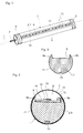
- the waterproof LED tube light 1, 1 ' accordinging to FIGS. 1 and 2 such as FIG. 4 comprises a heat sink longitudinal profile 2.1 with a longitudinal groove 6, in which an LED strip 10 is inserted and connected to the heat sink longitudinal profile 2.1.
- the LED strip 10 includes a plurality of longitudinally of the heat sink longitudinal profile 2.1 one behind the other and spaced from each other arranged LED units 15th
- the heat sink longitudinal profile 2.1 with the LED strip 10 is inserted into a translucent casing tube 3 made of plastic.
- the chemical and weather-resistant jacket tube 3 is made of transparent Teflon, for example.
- the sheath of the electric cable 7 is for example made of FPM.
- the sheathing tube 3 and its cross-sectional inner circumference are circular.
- the cross-sectional outer circumference of the heat sink profile 2.1 has a circular arc section 11 (contact arc section) which encloses an angle (center angle) of approximately 255 °.
- the heat sink profile 2.1 is flush with its circular arc section 11 on the sheathing tube 3 and thus forms with this a flat contact.
- the LED strip 10 is arranged in the groove bottom.
- a control electronics 12 for the LED units 15 is arranged in the longitudinal groove 6 (see FIG. 2 ).
- the depth of the longitudinal groove 6 is selected so that the electronic components 12, 15 arranged in the longitudinal groove 6 do not protrude beyond the longitudinal groove 6 towards the jacket tube 3.
- the cross-section of the sheathing tube 3 forms an unsupported circular arc section 13 which, together with the longitudinal groove 6, encloses a lighting cavity 8.
- the longitudinal groove 6 is bounded laterally in cross-sectional view by two profile flanks 9a, 9b.
- the jacket tube 3 rests against the profile flanks 9a, 9b on the outside and is supported by this before it passes into the unsupported circular arc section 13.
- the LED units 15 now radiate the light in the lamp cavity 8 to the sheath tube 3 out. Since the luminaire cavity 8 is not filled with a potting compound, the light does not show any change in intensity and color when it leaves the jacket tube 3. Due to the special design of sheath tube 3, heat sink profile 2.1 and contact portion 11 between sheath tube 3 and heat sink profile 2.1 of the light cavity 8 is dimensionally stable even at water pressures of 3 bar or higher.
- the heat sink profile 2.1 further includes on its, the longitudinal groove 6 opposite side another recess 18 or recess, in which a sensor unit 16 is arranged.
- the sensor unit 16 comprises a temperature sensor for measuring the temperature of the heat sink profile 2.1 and a heat protection switch, which interrupts the power supply to the LED units 15 in the event of overheating.
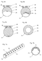
- FIGS. 5a to 5b show various embodiments of heat sink profiles 2.1-2.5.
- the geometry of the embodiments shown are adapted to LED strips of different widths. Accordingly, the heat sink profiles 2.1-2.5 in particular longitudinal grooves 6 of different width.
- the width of the longitudinal groove 6 can be varied while maintaining the radius of the heat sink profile 2.1-2.5 by different sized circular segments are removed at the output profile of the heat sink profile 2.1-2.5.
- FIGS. 6a to 6d four further embodiments of LED tube lights 21, 31, 41, 51 are shown, each of which in a sheath tube 23, 33, 43, 53 arranged heat sink profile 22, 32, 42, 52 included.
- the heat sink profile 22, 32 of the two embodiments according to FIGS. 6a and 6b has a cup-shaped profile incision. Between the two flanks of the cup-shaped profile incision extends an unsupported circular arc portion of the sheath tube 23, 33rd
- the cup-shaped profile incision contains a flat base surface on which an LED strip 25 is arranged.
- a groove-like depression is formed both in the base and in the lateral flanks of the cup-shaped profile incision.
- an LED strip 35 is arranged in each case.
- the two lateral LED strips 35 each have an inclination relative to the LED strip arranged on the base.
- the heat sink profile 42 in the form of a round rod.
- the heat sink profile 42 has a groove-shaped recess which receives an LED strip 45.
- the heat sink profile 52 in contrast to FIG. 6c as a round tube.
- the heat sink profile 52 also has a groove-shaped depression which receives an LED strip 55.
- the embodiments according to Figure 6a to 6c Incidentally, they have in common that they include a light fixture 24, 34, 44.
- the jacket tube 23, 33, 43 forms an opening 26, 36, 46 in the region of the lamp holder 24, 34, 44.
- the heat sink profile 22, 32, 42 is in the region of the opening 26, 36, 46 connected to the lamp holder 24, 34, 44, in particular connected flat. In this way, an additional, effective heat dissipation via the lamp holder 24, 34, 44 is achieved.
- FIGS. 7a and 7b Characterized by a held in a sheath tube 73 heat sink profile 72, which forms along its cross-sectional outer circumference three groove-shaped recesses, each receiving a radially outwardly directed LED strip 75.
- the LED strips 75 extend in the profile longitudinal direction L parallel to each other.
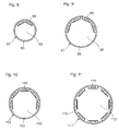
- FIGS. 8 to 11 show modifications of the embodiment according to Figure 7a, 7b according to which the LED lamp 81, 91, 101, 111 differ by the different number of groove-shaped depressions in the cross-sectional outer circumference of the heat sink profile 82, 92, 102, 112 and the LED strips 85, 95, 105, 115 arranged therein ,
- the embodiment detects FIG. 8 two groove-shaped recesses or LED strips 85, after FIG. 9 four groove-shaped depressions or LED strips 95, after FIG. 10 five groove-shaped recesses or LED strips 105 and after FIG. 11 eight groove-shaped depressions or LED strips 115 on.
- FIG. 11 are correspondingly full and at regular intervals groove-shaped depressions or LED strips 115 on the heat sink profile 112 arranged.
Landscapes
- Engineering & Computer Science (AREA)
- General Engineering & Computer Science (AREA)
- Non-Portable Lighting Devices Or Systems Thereof (AREA)
- Arrangement Of Elements, Cooling, Sealing, Or The Like Of Lighting Devices (AREA)
Abstract
Description
- Die Erfindung bezieht sich auf das Gebiet der LED (Light Emitting Diodes) Leuchten und betrifft im Speziellen eine wasserdichte LED-Leuchte zu Beleuchtungszwecken nach dem Oberbegriff des Anspruchs 1.
- Zu Beleuchtungszwecken bedeutet, dass die Leuchte zum emittieren von Licht zwecks Wahrnehmung durch das menschliche Auge ausgelegt ist.
- Es sind wasserdichte LED-Leuchten bekannt, welche als Rohrleuchten ausgebildet sind. Diese umfassen ein auf einem Kühlkörper-Profil aus Metall angeordnetes LED-Band mit einer Mehrzahl von LED-Einheiten. Das Kühlkörper-Profil mit LED-Band ist in einem Ummantelungsrohr gekapselt.
- Eine solche LED-Leuchte ist beispielsweise in der
EP 2 685 157 beschrieben. Die Anforderungen an wasserdichte LED-Leuchten sind sehr hoch und daher nicht vergleichbar mit den Anforderungen an herkömmliche LED-Leuchten für Innen- und Aussenanwendungen. - So müssen wasserdichte LED-Leuchten eine vollständige Dichtigkeit in Bezug auf Wasser aber auch in Bezug auf Wasserdampf aufweisen. Sie sollten ferner auch beständig gegen Chemikalien, wie Säuren oder Chlor sein, da Anwendungen im Nassbereich oftmals auch hohe Anforderungen an die Beständigkeit gegen reaktive Chemikalien stellen.
- Die wasserdichte LED-Leuchte in Unterwasser-Anwendungen muss auch dem ausgesetzten Wasserdruck standhalten, ohne deformiert zu werden. Ferner muss eine effiziente Wärmeableitung garantiert sein, um ein Überhitzen der leistungsfähigen LED-Einheiten zu vermeiden.
- Die
EP 2 685 157 beschreibt nun ein Verfahren, gemäss welchem der freie Hohlraum der LED-Rohrleuchte mit einer lichtdurchlässigen Vergussmassen vergossen wird, so dass die LED-Einheiten von einer Vergussmasse umgeben sind. Dies gewährleistet eine gute Abdichtung der LED-Einheiten gegen Wasser und Wasserdampf. Zudem sorgt die Vergussmasse für eine gute Festigkeit der LED-Rohrleuchte gegen den Wasserdruck. Die Vergussmasse unterstützt ferner die Wärmeabfuhr von den LED-Einheiten. - Die Vergussmasse hat allerdings den Nachteil, dass diese das Spektrum des abgestrahlten Lichtes verändert, so dass von aussen eine veränderte LED-Lichtfarbtemperatur wahrgenommen wird. Solche Effekte sind jedoch äusserst unerwünscht.
- Aufgabe vorliegender Erfindung ist es deshalb, eine wasserdichte LED-Leuchte vorzuschlagen, welche sowohl wasser- und wasserdampfdicht als auch beständig gegen Chemikalien ist, mit welchen das Wasser versetzt ist, und welche möglichst keine Veränderung der LED-Lichtfarbtemperatur sowie der Lichtintensität bewirkt.
- Im Weiteren soll die LED-Leuchte eine gute Ableitung der Wärme von den LED-Einheiten gewährleisten und dadurch hohe Lichtleistungen ermöglichen. Die LED-Leuchte soll zudem formstabil sein und dem Wasserdruck stand halten. Ferner soll die LED-Leuchte insbesondere auch UV- und Ozon-beständig sein.
- Die Aufgabe wird durch die Merkmale des Anspruchs 1 gelöst. Die abhängigen Ansprüche sowie die Beschreibung und die Zeichnungen beinhalten besondere Ausführungsformen und Weiterbildungen der Erfindung.
- Die LED-Leuchte enthält erfindungsgemäss ein Kühlkörper-Profil aus Metall mit mindestens einem darauf angeordneten LED-Band, welches eine Mehrzahl von LED-Einheiten umfasst.
- Die LED-Leuchte kann ein einzelnes LED-Band oder mehrere LED-Bänder umfassen.
- Das Kühlkörper-Profil mit dem mindestens einen LED-Band ist in einem lichtdurchlässigen Ummantelungsrohr gekapselt. Das mindestens eine LED-Band ist zu einem zwischen Ummantelungsrohr und Kühlkörper-Profil ausgebildeten Leuchtenhohlraum hin gerichtet, derart dass die LED-Einheiten Licht durch den Leuchtenhohlraum zum Ummantelungsrohr und durch das Ummantelungsrohr hindurch nach aussen abstrahlen können.
- Bei mehreren LED Bändern kann kann jedem LED-Band ein Leuchtenhohlraum zugeordnet sein, wobei die Leuchtenhohlräume über den Querschnitt der LED-Leuchte betrachtet insbesondere voneinander abgetrennt sind.
- Gemäss Erfindung bilden der Querschnittsinnenumfang des Ummantelungsrohrs und der Querschnittsaussenumfang des Kühlkörper-Profils jeweils mindestens einen Kontaktbogenabschnitt aus, wobei das Ummantelungsrohr und das Kühlkörper-Profil im Bereich der Kontaktbogenabschnitte einander anliegen.
- Das Ummantelungsrohr und das Kühlkörper-Profil können derart ausgebildet sein, dass das Ummantelungsrohr mit mindestens 40% seines Querschnittsinnenumfanges dem Querschnittsaussenumfang des Kühlkörper-Profils anliegt.
- Gemäss einer Weiterbildung der Erfindung liegt das Ummantelungsrohr mit mindestens der Hälfte seines Querschnittsinnenumfanges, insbesondere mit mehr als der Hälfte seines Querschnittsinnenumfanges dem Querschnittsaussenumfang des Kühlkörper-Profils an.
- Der Querschnittsinnenumfang des Ummantelungsrohres und der Querschnittsaussenumfang des Kühlkörper-Profils, mit welchem das Ummantelungsrohr dem Kühlkörper-Profil anliegt, kann sich aus einem einzelnen oder aus mehreren Kontaktbogenabschnitte zusammensetzen. Mehrere Kontaktbogenabschnitte können insbesondere durch Leuchtenhohlräume unterbrochen sein.
- So kann das Kühlkörperprofil mehrere entlang seines Querschnittsaussenumfanges angeordnete Kontaktbogenabschnitte ausbilden. Diese Kontaktbogenabschnitte können von nutförmigen Vertiefungen begrenzt sein. Die nutförmigen Vertiefungen nehmen jeweils insbesondere ein LED-Band auf.
- Kühlkörper-Profil und Ummantelungsrohr bilden in diesem Bereich einen flächigen Kontakt aus. Der Kontaktschluss zwischen Kühlkörper-Profil und Ummantelungsrohr ergibt eine hohe Stabilität.
- Das Kühlkörper-Profil liegt dem Ummantelungsrohr im genannten Bereich also insbesondere bündig bzw. eng an. Kühlkörper-Profil und Ummantelungsrohr bilden im Kontaktbereich insbesondere einen Reibschluss aus.
- Das Kühlkörper-Profil wird insbesondere über diesen flächigen Kontakt im Ummantelungsrohr verklemmt.
- Die Abschnittsgeometrien des Querschnittsaussenumfangs des Kühlkörper-Profils und des Querschnittsinnenumfangs des Ummantelungsrohrs, welche einander anliegen, sind insbesondere gegengleich zueinander ausgebildet.
- Da das Ummantelungsrohr insbesondere aus einem Fluorpolymer mit geringen Reibungswerten besteht, lässt sich das Kühlkörper-Profil trotz des vergleichsweise grossflächigen Kontaktes mit dem Ummantelungsrohr ohne grössere Umstände in das Ummantelungsrohr einschieben.
- Um das Einschieben des Kühlkörper-Profils in das Ummantelungsrohr zu ermöglichen bzw. zu erleichtem, kann das Ummantelungsrohr vorgängig erwärmt werden, wodurch dieses geringfügig dehnbar wird. Dieses Verfahren ist insbesondere bei langen LED-Leuchten von mehreren Metern Länge von Vorteil.
- Der flächige Kontakt zwischen Innenwand des Ummantelungsrohrs und Kühlkörper-Profil gewährleistet eine effiziente Wärmeableitung vom Kühlkörper-Profil durch das Ummantelungsrohr nach aussen.
- Die LED-Leuchte ist insbesondere als Längskörper ausgebildet. Der Längskörper bildet eine Längsachse aus. Die LED-Leuchte weist insbesondere eine Längserstreckung auf, welche einem Vielfachen des Querschnittsdurchmessers entspricht.
- Die LED-Leuchte kann entlang ihrer Längserstreckung geradlinig ausgebildet sein. Das heisst, die LED-Leuchte weist keine Krümmungen auf.
- Die LED-Leuchte mit dem Ummantelungsrohr ist insbesondere eine Rohrleuchte.
- Unter dem Begriff "Rohr" soll ein länglicher Hohlkörper verstanden werden, dessen Länge wesentlich größer als sein Durchmesser ist. Das Rohr kann definitionsgemäss formstabil sein oder als nicht formstabiler Schlauch ausgebildet sein. Letzterer Unterschied ist mit Bezugnahme auf die fertige LED-Leuchte insofern von begrenzter Bedeutung, als dass in das Ummantelungsrohr das Kühlkörper-Profil eingeschoben wird und dadurch auch ein nicht formstabiler Schlauch in eine formstabile Rohrform überführt wird.
- Gemäss einer Weiterbildung ist der Querschnittsinnenumfang des Ummantelungsrohrs rund, insbesondere kreisrund bzw. kreisförmig. Der Querschnittsinnenumfang des Ummantelungsrohrs kann auch oval oder ellipsenförmig sein.
- Gemäss einer Weiterbildung bildet der Querschnittsaussenumfang des Kühlkörper-Profils mindestens einen Kreisbogenabschnitt aus, welcher dem mindestens einem Kontaktbogenabschnitt entspricht. Das Kühlkörper-Profil liegt mit seinem mindestens einen Kreisbogenabschnitt dem Ummantelungsrohr innenseitig an. Die Radien des kreisförmigen Querschnittsinnenumfangs des Ummantelungsrohrs und des mindestens einen Kreisbogenabschnitts des Querschnittsaussenumfangs des Kühlkörper-Profils sind insbesondere identisch.
- Der besagte mindestens eine Kreisbogenabschnitt des Kühlkörper-Profils schliesst z. B. einen Winkel (Zentriwinkel) von 200° (Winkelgrad) oder grösser, insbesondere von 220° oder grösser, und bevorzugt von 240° oder grösser ein. Dies trifft insbesondere dann zu, wenn das Kühlkörper-Profil exakt einen Kreisbogenabschnitt ausbildet.
- Die LED-Leuchte kann eine Leuchtenhalterung umfassen. Die LED-Leuchte ist insbesondere über die Leuchtenhalterung an einer externen Struktur befestigbar.
- Das Ummantelungsrohr ist insbesondere witterungsbeständig, wasser- und wasserdampfdicht, temperaturfest, beständig gegen Chemikalien und schlagfest.
- Das Ummantelungsrohr besteht bevorzugt aus einem (Hochleistungs-) Kunststoff, insbesondere aus einem lichtdurchlässigen Fluorpolymer. Lichtdurchlässig bedeutet, dass das Material elektromagnetische Wellen im sichtbaren Bereich passieren lässt. Das Ummantelungsrohr ist insbesondere transparent. Insbesondere eine hohe Transparenz des Ummantelungsrohres gewährleistet einen optimalen Lichtdurchsatz.
- Als Fluorpolymer für das Ummantelungsrohr eignet sich z. B. ein fluoriertes Elastomer. Fluorierte Elastomere sind z. B. Fluorelastomere wie FKM nach DIN ISO 1629, früher auch FPM genannt. Andere Bezeichnungen sind auch FCM bzw. CFM, Fluorkautschuk oder Fluorcarbon-Elastomer. Fluorierte Elastomere können auch Kautschuke sein, die als gemeinsames Merkmal Vinyliden(di)fluorid (VDF) als eines ihrer Monomere besitzen.
- Das Fluorelastomer kann auch ein Mischpolymerisat aus fluorierten Kohlenwasserstoffen sein.
- Dies können zum Beispiel sein:
- Copolymere von Vinylidenfluorid (VDF) und Hexafluorpropylen (HFP) und
- Terpolymere von VDF, HFP und Tetrafluorethylen (TFE)
- Ferner ist auch die Verwendung von:
- Polymerisaten aus VDF, HFP, TFE und Perfluormethylvinylether (PMVE)
- Polymerisaten aus VDF, TFE und Propen, sowie
- Polymerisaten aus VDF, HFP, TFE, Perfluormethylvinylether (PMVE) und Ethen denkbar.
- Es können beispielsweise Fluorpolymere wie:
- Hexafluorpropylen/Vinylidenfluorid-Elastomer
- Vinylidenfluorid/Hexafluorpropylen/Tetrafluorethylen-Copolymer
- Copolymer aus Tetrafluorethylen und normalem Propylen (TFE P) Verwendung finden.
- Weitere, zur Verwendung mögliche fluorierte Elastomere wären:
- Perfluorkautschuk (FFKM)
- Tetrafluorethylen/Propylen-Kautschuke (FEPM)
- fluorierter Silikonkautschuk
- Ferner können auch fluorhaltige Copolymere, wie Tetrafluorethylen/Hexafluorpropylen-Copolymer (FEP), Ethylen/Tetrafluorethylen-Copolymer (ETFE) und Perfluoralkoxy-Copolymer (PFA) Verwendung finden. Letzteres wird auch unter dem Markennamen Teflon® vertrieben. Voraussetzung ist immer, dass die besagten Kunststoffe lichtdurchlässig und insbesondere transparent sind.
- Bevorzugt findet ein Fluorelastomer (FKM), ein Perfluoralkoxy-Copolymer (PFA) oder ein Ethylen/Tetrafluorethylen-Copolymer (ETFE) im Ummantelungsrohr Verwendung.
- Fluorpolymere der oben genannten Art zeichnen sich durch folgende Eigenschaften aus:
- Alterungsbeständigkeit
- Beständigkeit gegenüber Ozon-, Sauerstoff-, Alterungs- und Witterungseinflüssen
- UV-beständig
- Beständigkeit gegen Chemikalien, wie Säuren, Chlor, etc.
- elastische Eigenschaften
- flammwidrig und temperaturbeständig (z. B. in einem Temperaturbereich von -200 bis +200°C)
- elektrisch isolierend
- wasserabweisend
- geringer Reibungskoeffizient
- hohe mechanische Festigkeit, insbesondere schlagzäh
- anti-adhäsiv
- verfärbungsresistent
- gegebenenfalls thermoplastische Verarbeitbarkeit
- Das Ummantelungsrohr ist z. B. flexibel ausgebildet. Dies kann z. B. durch eine geringe Wandstärke erzielt werden. So kann das Ummantelungsrohr z. B. als Schlauch ausgebildet sein, welcher z. B. nicht formstabil ist. Ein als dünnwandige Aussenhülle ausgebildetes Ummantelungsrohr gewährleistet einen sehr guten Wärmeabfluss nach aussen.
- Es ist jedoch auch möglich, dass das Ummantelungsrohr formstabil ausgebildet ist. Das Ummantelungsrohr kann elastische Eigenschaften aufweisen.
- Das Umhüllungs- bzw. Ummantelungsrohr kann eine Wandstärke von 0.1 mm oder mehr, insbesondere von 0.2 mm oder mehr aufweisen. Das Ummantelungsrohr kann eine Wandstärke von 2 mm oder weniger, insbesondere von 1 mm oder weniger aufweisen.
- Das Ummantelungsrohr gewährleistet mit der angegebenen Wandstärke einen guten Wärmeabfluss und vermag dennoch die mechanischen, chemischen und physikalischen Anforderungen, wie den gewünschten Lichtdurchgangswert, zu erfüllen.
- Das Ummantelungsrohr ist im Querschnitt insbesondere geschlossen ausgebildet. Das Ummantelungsrohr weist bevorzugt lediglich ein oder zwei stirnseitig offene Enden auf.
- Gemäss einer besonderen Weiterbildung ist das Ummantelungsrohr entlang seines Querschnittsumfanges unterbrochen und weist eine Öffnung auf. Die Öffnung kann in Rohrlängsrichtung betrachtet abschnittsweise oder durchgehend ausgebildet sein.
- So kann die Öffnung z. B. eine sich in Rohrlängsrichtung durchgehend oder mit Unterbrechungen erstreckende Längsöffnung sein, welche z. B. schlitzförmig ist.
- Das Kühlkörper-Profil bildet über die Öffnung zweckmässig einen wärmeleitenden Kontakt, insbesondere Direktkontakt, mit einer Leuchtenhalterung aus. Das Kühlkörper-Profil ist über die Öffnung insbesondere mit der Leuchtenhalterung verbunden.
- Die Leuchtenhalterung kann so als Kühlkörpererweiterung dienen, über welche Wärmeenergie vom Kühlkörper-Profil an die Umgebung abgeführt wird. Durch die Öffnung im Ummantelungsrohr fällt dessen thermisch isolierende Wirkung weg.
- Das offene Ummantelungsrohr ist gegenüber der Leuchtenhalterung gegen den Eintritt von Wasser und Wasserdampf insbesondere abgedichtet.
- Das Ummantelungsrohr kann eine runde, insbesondere kreisrunde bzw. kreisförmige Querschnittsform aufweisen. Die Querschnittsform kann allerdings auch oval oder elliptisch sein.
- Das Kühlkörper-Profil dient wie bereits erwähnt als Kühlkörper und besteht daher aus einem gut wärmeleitenden Metall. Das Kühlkörper-Profil besteht insbesondere aus Aluminium oder einer Legierung davon. Kupfer oder eine Kupferlegierung ist ebenfalls denkbar. Ferner kann das Kühlkörper-Profil aus Nanopartikeln hergestellt sein.
- Es kann zum Beispiel auch vorgesehen sein, dass zur Verbesserung der Wärmeableitung Streifen aus Kupfer in die Vertiefung eines Kühlkörper-Profils aus Aluminium eingelegt werden, über welchen dann das LED-Band angeordnet wird.
- Das Kühlkörper-Profil liegt bevorzugt als Längsprofil vor. Das Kühlkörper-Profil ist insbesondere ein Rundprofil. Das Kühlkörper-Profil ist insbesondere als Vollprofil ausgebildet. Das Kühlkörper-Profil kann z. B. aus einer Rundstange hergestellt sein.
- Das Kühlkörper-Profil kann allerdings auch als Hohlprofil, d.h. als Rohrkörper, ausgebildet sein. Allerdings beträgt die Wanddicke des Rohrkörpers insbesondere mindestens 10%, ganz besonders mindestens 15% und zweckmässig mindestens 20% des Rohrdurchmessers.
- Das Kühlkörper-Profil weist insbesondere eine Längserstreckung auf, welche einem Vielfachen des grössten Querschnittsdurchmessers entspricht. Das Kühlkörper-Profil ist bevorzugt geradlinig ausgebildet.
- Die Querschnittsgeometrie kann dabei über die gesamte Längserstreckung des Kühlkörper-Profils gleichbleibend sein.
- Das Kühlkörper-Profil ist über seine Querschnittsform, d.h. quer zur Längsrichtung, insbesondere einteilig ausgebildet. Es ist auch möglich, dass das Kühlkörper-Profil über seine Querschnittsform mehrteilig ausgebildet ist.
- Das Kühlkörper-Profil kann über seine Querschnittsform auch zwiebelschalenartig aus mehreren schalenförmigen Teilprofilen zusammengesetzt sein, welche in Profillängsrichtung relativ zueinander verschiebbar angeordnet sind.
- Das Kühlkörper-Profil kann sich in Längsrichtung aus mehreren hintereinander angeordneten Teilprofilen zusammensetzen.
- Gemäss einer Weiterbildung der Erfindung bildet das Kühlkörper-Profil mindestens eine nutförmige Vertiefung, insbesondere eine Längsnut aus, in welcher das mindestens eine LED-Band angeordnet ist. Die mindestens eine nutförmige Vertiefung verläuft insbesondere parallel zur Profillängsrichtung. Die mindestens eine nutförmige Vertiefung kann z. B. mittels spanender Technik aus dem Kühlkörper-Profil herausgearbeitet, insbesondere gefräst sein.
- Die mindestens eine nutförmige Vertiefung wird z. B. aus einem Rundprofil hergestellt, indem vom Profilquerschnitt ein Kreisabschnitt abgetragen und, bezogen auf die Kreissehne, im Weiteren die Vertiefung, flankiert von zwei Profilflanken, eingebracht wird.
- Anstelle eines Kreisabschnittes kann auch eine becherförmige Vertiefung abgetragen werden und in der Basis und/oder in den Flanken der becherförmigen Vertiefung die mindestens eine nutförmige Vertiefung für das mindestens eine LED-Band eingebracht werden.
- Die mindestens eine nutförmige Vertiefung kann eine Querschnittsbreite aufweisen, welche mindestens die Hälfte, insbesondere mindestens zwei Drittel des grössten Querschnittsdurchmessers des Kühlkörper-Profils oder mehr beträgt. Dadurch wird gewährleistet, dass das Licht optimal von den LED-Einheiten zum Ummantelungsrohr abgestrahlt werden kann.
- Die mindestens eine nutförmige Vertiefung formt insbesondere zusammen mit dem Ummantelungsrohr den Leuchtenhohlraum.
- Der Leuchtenhohlraum enthält insbesondere ein Gas, wie Luft. Im Leuchtenhohlraum kann Atmosphärendruck oder ein Überdruck vorherrschen. Der Leuchtenhohlraum bildet eine formstabile (Luft-) Kammer aus.
- Gemäss einer Weiterbildung ist die mindestens eine nutförmige Vertiefung so ausgelegt ist, dass die Bauteile des LED-Bandes und gegebenenfalls weitere elektronische Bauteile, welche in der nutförmigen Vertiefung angeordnet sind zum Ummantelungsrohr hin nicht über die nutförmige Vertiefung hinausragen.
- Das Kühlkörper-Profil kann exakt eine nutförmige Vertiefung enthalten, in welcher mindestens ein LED-Band angeordnet ist.
- Es ist allerdings auch möglich, dass das Kühlkörper-Profil entlang seines Querschnittsaussenumfanges mehrere nutförmige Vertiefungen ausbildet, in welchen jeweils mindestens ein LED-Band angeordnet ist. Die nutförmigen Vertiefungen sind insbesondere radial nach aussen offen.
- Die LED-Bänder sind in den nutförmigen Vertiefungen insbesondere radial nach aussen weisend ausgerichtet. Die LED-Bänder verlaufen insbesondere parallel zueinander in Profillängsrichtung.
- Es ist grundsätzlich möglich, dass in einer nutförmigen Vertiefung auch mehrere LED-Bänder, insbesondere parallel zueinander angeordnet sind.
- Die nutförmigen Vertiefungen sind über jeweilige Profilflanken, wie nachfolgend noch erwähnt, gegenseitig voneinander abgegrenzt. Zwischen den Profilflanken zweier benachbarter nutförmiger Vertiefungen wird jeweils insbesondere ein Kontaktbogenabschnitt der weiter oben beschriebenen Art ausgebildet.
- Jede nutförmige Vertiefung bildet insbesondere einen separaten Leuchthohlraum aus.
- Das Ummantelungsrohr weist im Weiteren einen, den Leuchtenhohlraum begrenzenden, ungestützten Querschnittsumfangsabschnitt auf.
- Der ungestützte Querschnittsumfangsabschnitt bildet beispielsweise einen Bogen, insbesondere Kreisbogen aus. Der Kreisbogen schliesst insbesondere einen Winkel (Zentriwinkel) von 120° oder kleiner ein.
- Das Kühlkörper-Profil enthält insbesondere zwei, die nutförmige Vertiefung seitlich begrenzende Profilflanken, welchen das Ummantelungsrohr aussenseitig anliegt. Die Profilflanken stützen das Ummantelungsrohr bevor dieses in den ungestützten Querschnittsumfangsabschnitt übergeht.
- Gemäss einer Weiterbildung enthält das Kühlkörper-Profil eine weitere Ausnehmung, in welcher eine Sensoreinheit angeordnet ist. Die Ausnehmung ist in Profillängsrichtung insbesondere nicht durchgehend.
- Die Sensoreinheit umfasst einen Temperatursensor, welche die Temperatur des Kühlkörper-Profils misst. Die Sensoreinheit kann ferner einen Wärmeschutzschalter beinhalten, welcher die Stromzufuhr zu den LED-Einheiten bei einer Temperaturüberschreitung reguliert. Mittels der Sensoreinheit kann die Temperatur beispielsweise auch von extern via der LED-Steuerung reguliert werden, um so eine Überhitzung zu vermeiden.
- Das LED-Band ist insbesondere direkt in der nutförmigen Vertiefung auf das Kühlkörper-Profil aufgebracht, was eine optimale Wärmeabfuhr sicher stellt. Das LED-Band ist mit dem Kühlkörper-Profil insbesondere verbunden, z. B. über eine Klebverbindung.
- Zwischen dem Kühlkörper-Profil und dem LED-Band wird insbesondere ein direkter Wärmeschluss ausgebildet, womit eine optimale Wärmeabfuhr durch das Kühlkörper-Profil sichergestellt wird. Dies gewährleistet eine lange Lebensdauer der leistungsstarken Leuchtdioden.
- Das LED-Band kann z. B. eine Gesamthöhe von bis 5 mm aufweisen.
- Das LED-Band umfasst einen band- bzw. streifenförmigen LED-Träger mit Leiterbahnen, über welche den LED-Einheiten elektrische Energie und/oder Steuersignale übermittelt werden. Der streifenförmige LED-Träger ist bevorzugt flexibel, d.h. biegsam ausgebildet. Der streifenförmige LED-Träger weist zum Beispiel eine Dicke von 0.1 bis 2 mm auf.
- Auf dem streifenförmigen LED-Träger sind eine Mehrzahl von LED-Einheiten in Längserstreckung des LED-Bandes hintereinander und z. B. in Abstand zueinander angeordnet. Die LED-Einheiten sind zum Beispiel als LED-Chips ausgebildet. Die LED-Einheiten sind auf dem streifenförmigen LED-Träger befestigt. Der LED-Träger entspricht dabei der Platine.
- Entsprechend bildet das LED-Band, umfassend LED-Einheiten und Leiterbahnen auf dem streifenförmigen LED-Träger eine vollständige Funktionseinheit aus.
- Das Ummantelungsrohr weist insbesondere zwei offene Rohrenden auf. Das Ummantelungsrohr ist insbesondere von einem als Langware, z. B. Rollenware, vorliegenden Ummantelungsrohr auf Mass zugeschnitten.
- Die LED-Leuchte bzw. das dazugehörige Ummantelungsrohr ist an den offenen Enden über jeweils eine Dichtungsanordnung wasser- und wasserdampfdicht nach aussen abgedichtet. Die Dichtungsanordnung ist insbesondere (wasser-) druckbeständig (z. B. bis 10 bar) sowie auch beständig gegen Chemikalien der bereits genannten Art.
- Die Dichtungsanordnung kann ein Verschlusselement enthalten, welches in das offene Rohrende eingreift und/oder dieses übergreift.
- Das Verschlusselement kann ein Stopfen sein, welcher mit einem Abschnitt in das offene Rohrende eingeführt ist. Das Verschlusselement kann auch eine Kappe sein, welche mit einem Abschnitt über das offene Rohrende geschoben ist.
- Ferner kann die Dichtungsanordnung Dichtungselemente, wie Dichtungsringe enthalten, welche die Verbindung zwischen Verschlusselement und Ummantelungsrohr abdichten.
- Die Dichtungsanordnung verschliesst die Rohrenden jeweils fest mechanisch.
- Die Leitungsverbindungen sind beispielsweise über das wenigstens eine Rohrende in das Innere der Leuchte geführt. Die Leitungsverbindungen werden zum Beispiel durch das Verschlusselement geführt.
- Um das Eindiffundieren chemischer Substanzen zu verhindern, sind die am Anfang und Ende des Ummantelungsrohrs angebrachten Dichtungsanordnungen, insbesondere deren Dichtelemente, bevorzugt auch chemisch beständig.
- Die Dichtelemente können aus einem Fluorpolymer, beispielsweise aus einem FPM (Fluorelastomer), insbesondere aus einem der oben aufgeführten Fluorelastomer sein.
- Das Einbringen von LED-Bändern in Ummantelungsrohre ermöglicht die Herstellung von LED-Leuchten von mehreren Meter Länge.
- Die erfindungsgemässe LED-Leuchte ist insbesondere eine LED-Unterwasser-Leuchte für Unterwasser-Anwendungen.
- Die erfindungsgemässe LED-Leuchte findet insbesondere Verwendung in Schwimmbädern, Poolanlagen, in Wellness-Anlagen, in Brunnenanlagen, in Teichen, in Brunnenstuben von Trinkwasserversorgungen, in Autowaschanlagen, in stehenden Gewässern, in Fliesswasserbereichen und generell in Nassbereichen, wo ein permanenter oder temporärer Kontakt der LED-Leuchte mit Wasser und Wasserdampf sowie Chemikaliendämpfe möglich sein soll.
- Die LED-Leuchte kann z. B. eine Länge von 5 cm bis zu 10 m aufweisen. Der Innendurchmesser der LED-Leuchte kann 5 bis 30 mm, insbesondere 10 bis 20 mm aufweisen. Innendurchmesser von grösser 30 mm sind allerdings ebenfalls möglich. Im entsprechend gleichen Bereich kann der grösste Durchmesser des Kühlkörper-Profils liegen.
- Die LED-Leuchte ist für Wasserdrücke von 3 bar oder mehr geeignet, ohne dass diese z. B. deformiert und die LED-Einheiten beschädigt würden. Die grossflächige Wandberührung des Kühlkörper-Profils sorgt einerseits für eine hohe Festigkeit der Leuchte sowie für eine ausgezeichnete Wärmeableitung. Dadurch lassen sich besonders lichtstarke LED-Einheiten einsetzen.
- Im Folgenden wird der Erfindungsgegenstand jeweils anhand eines Ausführungsbeispiels, welches in den beiliegenden Zeichnungen dargestellt ist, näher erläutert. Es zeigen jeweils schematisch:
- Figur 1
- eine perspektivische Ansicht einer LED-Rohrleuchte;
- Figur 2
- eine Querschnittsansicht der LED-Rohrleuchte gemäss
Figur 1 ; - Figur 3
- eine Querschnittsansicht eines Kühlkörper-Profils;
- Figur 4
- eine perspektivische Ansicht einer weiteren LED-Rohrleuchte;
- Figur 5a-5d
- Querschnittsansichten von weiteren Kühlkörper-Profilen;
- Figur 6a-6d
- Querschnittsansichten von weiteren LED-Rohrleuchten;
- Figur 7a
- eine perspektivische Ansicht einer weiteren LED-Rohrleuchte;
- Figur 7b
- eine Querschnittsansicht der LED-Rohrleuchte gemäss
Figur 7a ; - Figur 8
- Querschnittsansicht einer weiteren LED-Rohrleuchte;
- Figur 9
- Querschnittsansicht einer weiteren LED-Rohrleuchte;
- Figur 10
- Querschnittsansicht einer weiteren LED-Rohrleuchte;
- Figur 11
- Querschnittsansicht einer weiteren LED-Rohrleuchte.
- Grundsätzlich sind in den Figuren gleiche Teile mit gleichen Bezugszeichen versehen.
- Die wasserdichte LED-Rohrleuchte 1, 1' gemäss
Figur 1 und 2 sowieFigur 4 umfasst ein Kühlkörper-Längsprofil 2.1 mit einer Längsnut 6, in welche ein LED-Band 10 eingelegt und mit dem Kühlkörper-Längsprofil 2.1 verbunden ist. Das LED-Band 10 enthält eine Mehrzahl von in Längsrichtung des Kühlkörper-Längsprofil 2.1 hintereinander und voneinander beabstandet angeordnete LED-Einheiten 15. - Das Kühlkörper-Längsprofil 2.1 mit dem LED-Band 10 ist in ein lichtdurchlässiges Ummantelungsrohr 3 aus Kunststoff eingeschoben.
- Das chemikalien- und witterungsbeständige Ummantelungsrohr 3 ist beispielsweise aus transparentem Teflon. Die Ummantelung des Elektrokabels 7 ist beispielsweise aus FPM.
- Das Ummantelungsrohr 3 und entsprechend sein Querschnittsinnenumfang sind kreisförmig ausgebildet.
- Der Querschnittsaussenumfang des Kühlkörper-Profils 2.1 weist einen Kreisbogenabschnitt 11 (Kontaktbogenabschnitt), welcher einen Winkel (Zentriwinkel) von ungefähr 255° einschliesst. Das Kühlkörper-Profil 2.1 liegt mit seinem Kreisbogenabschnitt 11 bündig am Ummantelungsrohr 3 an und bildet so mit diesem einen flächigen Kontakt aus.
- Das LED-Band 10 ist im Nutboden angeordnet. Im Weiteren ist in der Längsnut 6 auch eine Steuerungselektronik 12 für die LED-Einheiten 15 angeordnet (siehe
Figur 2 ). - Die Tiefe der Längsnut 6, ist so gewählt, dass die in der Längsnut 6 angeordneten Elektronik-Komponenten 12, 15 zum Ummantelungsrohr 3 hin nicht über die Längsnut 6 hinausragen.
- Der Querschnitt des Ummantelungsrohrs 3 bildet einen ungestützten Kreisbogenabschnitt 13 aus, welcher zusammen mit der Längsnut 6 einen Leuchtenhohlraum 8 einschliesst.
- Die Längsnut 6 wird in Querschnittsansicht seitlich von zwei Profilflanken 9a, 9b begrenzt. Das Ummantelungsrohr 3 liegt den Profilflanken 9a, 9b aussenseitig an und wird durch diese gestützt bevor dieses in den ungestützten Kreisbogenabschnitt 13 übergeht.
- Die LED-Einheiten 15 strahlen nun das Licht in den Leuchtenhohlraum 8 zum Ummantelungsrohr 3 hin ab. Da der Leuchtenhohlraum 8 nicht mit einer Vergussmasse, verfüllt ist, weist das Licht beim Verlassen des Ummantelungsrohrs 3 keine Veränderung in der Intensität und der Farbe auf. Durch die besondere Ausbildung von Ummantelungsrohr 3, Kühlkörper-Profil 2.1 und Kontaktabschnitt 11 zwischen Ummantelungsrohr 3 und Kühlkörper-Profil 2.1 ist der Leuchtenhohlraum 8 auch bei Wasserdrücken von 3 bar oder höher formstabil.
- Das Kühlkörper-Profil 2.1 enthält ferner auf seiner, der Längsnut 6 gegenüber liegenden Seite eine weitere Ausnehmung 18 bzw. Vertiefung, in welcher eine Sensoreinheit 16 angeordnet ist. Die Sensoreinheit 16 umfasst einen Temperatursensor zum Messen der Temperatur des Kühlkörper-Profils 2.1 sowie einen Wärmeschutzschalter, welcher bei einer Überhitzung die Stromzufuhr zu den LED-Einheiten 15 unterbricht.
- Während die LED-Leuchte gemäss Ausführungsform nach
Figur 4 noch nicht endseitig verschlossen ist, sind die Rohrenden der Ausführungsform nachFigur 1 jeweils mittels einer Dichtungsanordnung 4, 5 mit Rohrstopfen abgedichtet. Durch die eine Dichtungsanordnung 4 bzw. Rohrstopfen ist das Leitungskabel 7 hindurchgeführt. - Die
Figuren 3 sowie 5a bis 5b zeigen verschiedene Ausführungsformen von Kühlkörper-Profilen 2.1-2.5. Die Geometrie der gezeigten Ausführungsformen sind an LED-Bänder von unterschiedlichen Breiten angepasst. Entsprechend weisen die Kühlkörper-Profile 2.1-2.5 insbesondere Längsnuten 6 von unterschiedlicher Breite auf. - Die Breite der Längsnut 6 lässt sich bei gleichbleibendem Radius des Kühlkörper-Profils 2.1-2.5 dadurch variieren, indem unterschiedlich grosse Kreissegmente am Ausgangsprofil des Kühlkörper-Profils 2.1-2.5 abgetragen werden.
- In den
Figuren 6a bis 6d werden vier weitere Ausführungsformen von LED-Rohrleuchten 21, 31, 41, 51 gezeigt, welche jeweils ein in einem Ummantelungsrohr 23, 33, 43, 53 angeordnetes Kühlkörper-Profil 22, 32, 42, 52 enthalten. - Das Kühlkörper-Profil 22, 32 der beiden Ausführungsformen nach
Figur 6a und 6b weist einen becher-förmigen Profil-Einschnitt auf. Zwischen den beiden Flanken des becher-förmigen Profil-Einschnitt erstreckt sich ein ungestützter Kreisbogenabschnitt des Ummantelungsrohrs 23, 33. - Gemäss der Ausführungsform nach
Figur 6a enthält der becher-förmige Profil-Einschnitt eine ebene Basisfläche, auf welcher ein LED-Band 25 angeordnet ist. - Gemäss der Ausführungsform nach
Figur 6b ist sowohl in der Basis als auch in den seitlichen Flanken des becher-förmigen Profil-Einschnittes jeweils eine nutartige Vertiefung ausgebildet. In den nutartigen Vertiefungen ist jeweils ein LED-Band 35 angeordnet. Die beiden seitlichen LED-Bänder 35 weisen gegenüber dem an der Basis angeordneten LED-Band jeweils eine Neigung auf. - Gemäss der Ausführungsform nach
Figur 6c liegt das Kühlkörper-Profil 42 in Form einer Rundstange vor. Das Kühlkörper-Profil 42 weist eine nutförmige Vertiefung auf, welche ein LED-Band 45 aufnimmt. - Gemäss der Ausführungsform nach
Figur 6d liegt das Kühlkörper-Profil 52 im Gegensatz zuFigur 6c als Rundrohr vor. Das Kühlkörper-Profil 52 weist ebenfalls eine nutförmige Vertiefung auf, welche ein LED-Band 55 aufnimmt. - Die Ausführungsformen nach
Figur 6a bis 6c haben im übrigen gemeinsam, dass diese eine Leuchtenhalterung 24, 34, 44 umfassen. Das Ummantelungsrohr 23, 33, 43 bildet im Bereich der Leuchtenhalterung 24, 34, 44 eine Öffnung 26, 36, 46 aus. Das Kühlkörper-Profil 22, 32, 42 ist im Bereich der Öffnung 26, 36, 46 mit der Leuchtenhalterung 24, 34, 44 verbunden, insbesondere flächig verbunden. Auf diese Weise wird eine zusätzliche, effektive Wärmeabfuhr über die Leuchtenhalterung 24, 34, 44 erzielt. - Die Ausführungsform nach
Figur 7a und 7b zeichnet sich durch ein in einem Ummantelungsrohr 73 gehaltenen Kühlkörper-Profil 72 aus, welches entlang seines Querschnittsaussenumfanges drei nutförmige Vertiefungen ausbildet, welche jeweils ein radial nach aussen gerichtetes LED-Band 75 aufnehmen. Die LED-Bänder 75 verlaufen in Profillängsrichtung L parallel zueinander. - Die Ausführungsformen nach
Figur 8 bis 11 zeigen Abwandlungen der Ausführungsform nachFigur 7a, 7b , gemäss welchen sich die LED-Leuchte 81, 91, 101, 111 durch die unterschiedliche Anzahl der nutförmigen Vertiefungen im Querschnittsaussenumfang des Kühlkörper-Profils 82, 92, 102, 112 und der darin angeordneten LED-Bändern 85, 95, 105, 115 unterscheiden. - So weist die Ausführungsform nach
Figur 8 zwei nutförmige Vertiefungen bzw. LED-Bänder 85, nachFigur 9 vier nutförmige Vertiefungen bzw. LED-Bänder 95, nachFigur 10 fünf nutförmige Vertiefungen bzw. LED-Bänder 105 und nachFigur 11 acht nutförmige Vertiefungen bzw. LED-Bänder 115 auf. - Gemäss der Ausführungsform nach
Figur 11 sind entsprechend vollumfänglich und in regelmässigen Abständen zueinander nutförmige Vertiefungen bzw. LED-Bänder 115 am Kühlkörper-Profil 112 angeordnet.
Claims (15)
- Wasserdichte LED-Leuchte (1) zu Beleuchtungszwecken, enthaltend ein Kühlkörper-Profil (2.1) aus Metall mit mindestens einem darauf angeordneten LED-Band (10) mit einer Mehrzahl von LED-Einheiten (15), wobei das Kühlkörper-Profil (2.1) mit dem mindestens einen LED-Band (10) in einem lichtdurchlässigen Ummantelungsrohr (3) gekapselt ist, wobei das mindestens eine LED-Band (10) zu einem zwischen Ummantelungsrohr (3) und Kühlkörper-Profil (2.1) ausgebildeten Leuchtenhohlraum (8) hin gerichtet ist, derart dass die LED-Einheiten (15) Licht durch den Leuchtenhohlraum (8) zum Ummantelungsrohr (3) und durch das Ummantelungsrohr (3) hindurch nach aussen abstrahlen können,
dadurch gekennzeichnet, dass
der Querschnittsinnenumfang des Ummantelungsrohrs (3) und der Querschnittsaussenumfang des Kühlkörper-Profils (2.1) jeweils mindestens einen Kontaktbogenabschnitt (11) ausbilden, und das Ummantelungsrohr (3) und das Kühlkörper-Profil (2.1) im Bereich der Kontaktbogenabschnitte (11) einander anliegen. - LED-Leuchte nach Anspruch 1, dadurch gekennzeichnet, dass das Ummantelungsrohr (3) und das Kühlkörper-Profil (2.1) derart ausgebildet sind, dass das Ummantelungsrohr (3) mit mindestens 40% seines Querschnittsinnenumfanges dem Querschnittsaussenumfang des Kühlkörper-Profils (2.1) anliegt.
- LED-Leuchte nach Anspruch 1 oder 2, dadurch gekennzeichnet, dass das Ummantelungsrohr (3) mit mindestens der Hälfte seines Quersclmittsinnenumfanges dem Querschnittsaussenumfang des Kühlkörper-Profils (2.1) anliegt.
- LED-Leuchte nach einem der Ansprüche 1 bis 3, dadurch gekennzeichnet, dass das Kühlkörper-Profil (2.1) mindestens eine nutförmige Vertiefung (6) ausbildet, in welcher das mindestens eine LED-Band (10) angeordnet ist.
- LED-Leuchte nach einem der Ansprüche 1 bis 4, dadurch gekennzeichnet, dass das Kühlkörper-Profil (2.1) mehrere nutförmige Vertiefungen (6) ausbildet, in welchen jeweils mindestens ein LED-Band (10) angeordnet ist.
- LED-Leuchte nach einem der Ansprüche 1 bis 5, dadurch gekennzeichnet, dass die mindestens eine nutförmige Vertiefung (6) so ausgelegt ist, dass die Bauteile des mindestens einen LED-Bandes (10) zum Ummantelungsrohr (3) hin nicht über die nutförmige Vertiefung (6) hinausragen.
- LED-Leuchte nach einem der Ansprüche 1 bis 6, dadurch gekennzeichnet, dass der Querschnittsinnenumfang des Ummantelungsrohrs (3) kreisförmig ist und der Querschnittsaussenumfang des Kühlkörper-Profils (2.1) mindestens einen Kreisbogenabschnitt (11) ausbildet, und das Kühlkörper-Profil (2.1) mit seinem mindestens einen Kreisbogenabschnitt (11) dem Ummantelungsrohr (3) anliegt.
- LED-Leuchte nach Anspruch 7, dadurch gekennzeichnet, dass der mindestens eine Kreisbogenabschnitt (11) einen Winkel (Zentriwinkel) von 200° oder grösser, insbesondere von 220° oder grösser, und bevorzugt von 240° oder grösser einschliesst.
- LED-Leuchte nach einem der Ansprüche 1 bis 8, dadurch gekennzeichnet, dass das Kühlkörper-Profil (2.1) zwei, die mindestens eine nutförmige Vertiefung (6) begrenzende Profilflanken (9a, 9b) enthält, welchen das Ummantelungsrohr (3) anliegt.
- LED-Leuchte nach einem der Ansprüche 1 bis 9, dadurch gekennzeichnet, dass das Ummantelungsrohr (3) aus einem Fluorpolymer, insbesondere aus einem Fluorisierten Elastomer, aus einem Perfluoralkoxy-Copolymer (PFA) oder Ethylen/Tetrafluorethylen-Copolymer (ETFE) besteht.
- LED-Leuchte nach einem der Ansprüche 1 bis 10, dadurch gekennzeichnet, dass das Ummantelungsrohr (3) eine Wandstärke von 0.1 bis 2 mm, insbesondere von 0.2 bis 1 mm aufweist.
- LED-Leuchte nach einem der Ansprüche 1 bis 11, dadurch gekennzeichnet, dass das Ummantelungsrohr (3) mindestens einen den Leuchtenhohlraum (8) begrenzenden, ungestützten Querschnittsumfangsabschnitt (13) aufweist.
- LED-Leuchte nach Anspruch 12, dadurch gekennzeichnet, dass der ungestützte Querschnittsumfangsabschnitt (13) einen Kreisbogen ausbildet, welcher insbesondere einen Winkel (Zentriwinkel) von 120° oder kleiner einschliesst.
- LED-Leuchte nach einem der Ansprüche 1 bis 13, dadurch gekennzeichnet, dass das Kühlkörper-Profil (2.1) wenigstens eine weitere Ausnehmung (18) enthält, in welcher eine Sensoreinheit (16) angeordnet ist.
- LED-Leuchte nach einem der Ansprüche 1 bis 14, dadurch gekennzeichnet, dass das Ummantelungsrohr (23, 33,43) entlang seines Querschnittsumfanges unterbrochen ist und eine Öffnung (26, 36, 46) aufweist und das Kühlkörper-Profil (22, 32, 42) über die Öffnung (26, 36, 46) mit einer Leuchtenhalterung (24, 34, 44) einen wärmeleitenden Kontakt ausbildet.
Applications Claiming Priority (1)
| Application Number | Priority Date | Filing Date | Title |
|---|---|---|---|
| CH11542015 | 2015-08-11 |
Publications (2)
| Publication Number | Publication Date |
|---|---|
| EP3130846A1 true EP3130846A1 (de) | 2017-02-15 |
| EP3130846B1 EP3130846B1 (de) | 2018-08-01 |
Family
ID=54065136
Family Applications (1)
| Application Number | Title | Priority Date | Filing Date |
|---|---|---|---|
| EP16182911.4A Active EP3130846B1 (de) | 2015-08-11 | 2016-08-05 | Wasserdichte led-leuchte |
Country Status (1)
| Country | Link |
|---|---|
| EP (1) | EP3130846B1 (de) |
Cited By (1)
| Publication number | Priority date | Publication date | Assignee | Title |
|---|---|---|---|---|
| EP4375563A1 (de) | 2022-11-24 | 2024-05-29 | Ferdinand Pfleghart | Led- profilleuchte |
Citations (7)
| Publication number | Priority date | Publication date | Assignee | Title |
|---|---|---|---|---|
| US20050104059A1 (en) * | 2003-11-14 | 2005-05-19 | Friedman Marc D. | Flexible array |
| US20100214785A1 (en) * | 2009-02-23 | 2010-08-26 | Chen Hui Yu | Waterproof lighting fixture |
| US20100220469A1 (en) * | 2008-05-23 | 2010-09-02 | Altair Engineering, Inc. | D-shaped cross section l.e.d. based light |
| DE202011052030U1 (de) * | 2011-11-18 | 2012-02-27 | Eiko Electric Products Corp. | Unterwasser-LED-Beleuchtungsvorrichtung |
| DE102012201788A1 (de) * | 2011-11-18 | 2013-05-23 | Tridonic Jennersdorf Gmbh | Rohrförmige LED-Lampe |
| EP2685157A2 (de) * | 2012-07-09 | 2014-01-15 | Ferdinand Pfleghart | Wasserdampfdichte LED-Profil-Leuchte |
| CN203533241U (zh) * | 2013-07-26 | 2014-04-09 | 晋宝电气(浙江)有限公司 | 一种灯具 |
-
2016
- 2016-08-05 EP EP16182911.4A patent/EP3130846B1/de active Active
Patent Citations (7)
| Publication number | Priority date | Publication date | Assignee | Title |
|---|---|---|---|---|
| US20050104059A1 (en) * | 2003-11-14 | 2005-05-19 | Friedman Marc D. | Flexible array |
| US20100220469A1 (en) * | 2008-05-23 | 2010-09-02 | Altair Engineering, Inc. | D-shaped cross section l.e.d. based light |
| US20100214785A1 (en) * | 2009-02-23 | 2010-08-26 | Chen Hui Yu | Waterproof lighting fixture |
| DE202011052030U1 (de) * | 2011-11-18 | 2012-02-27 | Eiko Electric Products Corp. | Unterwasser-LED-Beleuchtungsvorrichtung |
| DE102012201788A1 (de) * | 2011-11-18 | 2013-05-23 | Tridonic Jennersdorf Gmbh | Rohrförmige LED-Lampe |
| EP2685157A2 (de) * | 2012-07-09 | 2014-01-15 | Ferdinand Pfleghart | Wasserdampfdichte LED-Profil-Leuchte |
| CN203533241U (zh) * | 2013-07-26 | 2014-04-09 | 晋宝电气(浙江)有限公司 | 一种灯具 |
Cited By (2)
| Publication number | Priority date | Publication date | Assignee | Title |
|---|---|---|---|---|
| EP4375563A1 (de) | 2022-11-24 | 2024-05-29 | Ferdinand Pfleghart | Led- profilleuchte |
| CH720262A1 (de) * | 2022-11-24 | 2024-05-31 | Pfleghart Ferdinand | LED-Leuchte mit Kühlkörperprofil. |
Also Published As
| Publication number | Publication date |
|---|---|
| EP3130846B1 (de) | 2018-08-01 |
Similar Documents
| Publication | Publication Date | Title |
|---|---|---|
| DE69810404T2 (de) | Lineare Lichtquelle | |
| EP2697565B1 (de) | Explosionsgeschütztes led-modul | |
| DE10322561A9 (de) | Glaselement mit Lichtrahmen | |
| DE102011051038A1 (de) | LED Beleuchtungsanordnung | |
| WO2009121559A1 (de) | Leuchte | |
| DE3135874A1 (de) | Niederdruckquecksilberdampfentladungslampe | |
| DE102016219904B4 (de) | Dichtungsprofil, verschließbare Öffnung | |
| CH710916A1 (de) | Linearleuchte und Trägerprofil für eine Linearleuchte. | |
| EP3130846B1 (de) | Wasserdichte led-leuchte | |
| DE102011051034A1 (de) | LED Beleuchtungsanordnung | |
| EP2824380B1 (de) | Leuchte | |
| DE102011084945A1 (de) | LED-Leuchte | |
| EP3460321B1 (de) | Leuchtvorrichtung | |
| EP2957815B1 (de) | Beleuchtungskörper mit mindestens einem led-streifen | |
| EP1813857A1 (de) | Lichtquelle | |
| DE102019121916B4 (de) | Langgestreckte Industrieleuchte | |
| EP2404289A1 (de) | Leuchtvorrichtung mit einem grundkörper aus lichtdurchlässigem material | |
| EP2685157A2 (de) | Wasserdampfdichte LED-Profil-Leuchte | |
| DE102013113566A1 (de) | Lichtröhre mit wenig nach unten gerichtetem Licht | |
| EP4375563A1 (de) | Led- profilleuchte | |
| DE202017106173U1 (de) | Länglicher, deckenmontierter Dreifachschutz -LED-Leuchtenaufbau | |
| DE202011050646U1 (de) | Leuchtröhre | |
| EP3771787B1 (de) | Unterwasserleuchte | |
| EP3184891B1 (de) | Leuchtensystem umfassend mehrere leuchteinheiten | |
| CH711562B1 (de) | Optische Folie und Leuchte mit einer solchen. |
Legal Events
| Date | Code | Title | Description |
|---|---|---|---|
| PUAI | Public reference made under article 153(3) epc to a published international application that has entered the european phase |
Free format text: ORIGINAL CODE: 0009012 |
|
| STAA | Information on the status of an ep patent application or granted ep patent |
Free format text: STATUS: THE APPLICATION HAS BEEN PUBLISHED |
|
| AK | Designated contracting states |
Kind code of ref document: A1 Designated state(s): AL AT BE BG CH CY CZ DE DK EE ES FI FR GB GR HR HU IE IS IT LI LT LU LV MC MK MT NL NO PL PT RO RS SE SI SK SM TR |
|
| AX | Request for extension of the european patent |
Extension state: BA ME |
|
| STAA | Information on the status of an ep patent application or granted ep patent |
Free format text: STATUS: REQUEST FOR EXAMINATION WAS MADE |
|
| RBV | Designated contracting states (corrected) |
Designated state(s): AL AT BE BG CH CY CZ DE DK EE ES FI FR GB GR HR HU IE IS IT LI LT LU LV MC MK MT NL NO PL PT RO RS SE SI SK SM TR |
|
| 17P | Request for examination filed |
Effective date: 20170810 |
|
| RIC1 | Information provided on ipc code assigned before grant |
Ipc: F21V 29/89 20150101ALN20171214BHEP Ipc: F21V 31/04 20060101ALN20171214BHEP Ipc: F21V 3/04 20180101ALI20171214BHEP Ipc: F21V 31/00 20060101AFI20171214BHEP Ipc: F21K 9/90 20160101ALN20171214BHEP Ipc: F21W 131/401 20060101ALN20171214BHEP Ipc: F21Y 115/10 20160101ALN20171214BHEP Ipc: F21Y 101/00 20160101ALN20171214BHEP Ipc: F21V 29/70 20150101ALI20171214BHEP Ipc: F21Y 103/10 20160101ALN20171214BHEP Ipc: F21S 4/28 20160101ALI20171214BHEP |
|
| GRAP | Despatch of communication of intention to grant a patent |
Free format text: ORIGINAL CODE: EPIDOSNIGR1 |
|
| STAA | Information on the status of an ep patent application or granted ep patent |
Free format text: STATUS: GRANT OF PATENT IS INTENDED |
|
| INTG | Intention to grant announced |
Effective date: 20180205 |
|
| GRAS | Grant fee paid |
Free format text: ORIGINAL CODE: EPIDOSNIGR3 |
|
| GRAA | (expected) grant |
Free format text: ORIGINAL CODE: 0009210 |
|
| STAA | Information on the status of an ep patent application or granted ep patent |
Free format text: STATUS: THE PATENT HAS BEEN GRANTED |
|
| AK | Designated contracting states |
Kind code of ref document: B1 Designated state(s): AL AT BE BG CH CY CZ DE DK EE ES FI FR GB GR HR HU IE IS IT LI LT LU LV MC MK MT NL NO PL PT RO RS SE SI SK SM TR |
|
| REG | Reference to a national code |
Ref country code: GB Ref legal event code: FG4D Free format text: NOT ENGLISH |
|
| REG | Reference to a national code |
Ref country code: CH Ref legal event code: EP Ref country code: AT Ref legal event code: REF Ref document number: 1024732 Country of ref document: AT Kind code of ref document: T Effective date: 20180815 |
|
| REG | Reference to a national code |
Ref country code: IE Ref legal event code: FG4D Free format text: LANGUAGE OF EP DOCUMENT: GERMAN |
|
| REG | Reference to a national code |
Ref country code: DE Ref legal event code: R096 Ref document number: 502016001574 Country of ref document: DE |
|
| REG | Reference to a national code |
Ref country code: CH Ref legal event code: NV Representative=s name: FREI PATENTANWALTSBUERO AG, CH |
|
| REG | Reference to a national code |
Ref country code: CH Ref legal event code: PCAR Free format text: NEW ADDRESS: POSTFACH, 8032 ZUERICH (CH) |
|
| REG | Reference to a national code |
Ref country code: NL Ref legal event code: MP Effective date: 20180801 |
|
| REG | Reference to a national code |
Ref country code: LT Ref legal event code: MG4D |
|
| PG25 | Lapsed in a contracting state [announced via postgrant information from national office to epo] |
Ref country code: FI Free format text: LAPSE BECAUSE OF FAILURE TO SUBMIT A TRANSLATION OF THE DESCRIPTION OR TO PAY THE FEE WITHIN THE PRESCRIBED TIME-LIMIT Effective date: 20180801 Ref country code: LT Free format text: LAPSE BECAUSE OF FAILURE TO SUBMIT A TRANSLATION OF THE DESCRIPTION OR TO PAY THE FEE WITHIN THE PRESCRIBED TIME-LIMIT Effective date: 20180801 Ref country code: IS Free format text: LAPSE BECAUSE OF FAILURE TO SUBMIT A TRANSLATION OF THE DESCRIPTION OR TO PAY THE FEE WITHIN THE PRESCRIBED TIME-LIMIT Effective date: 20181201 Ref country code: NL Free format text: LAPSE BECAUSE OF FAILURE TO SUBMIT A TRANSLATION OF THE DESCRIPTION OR TO PAY THE FEE WITHIN THE PRESCRIBED TIME-LIMIT Effective date: 20180801 Ref country code: BG Free format text: LAPSE BECAUSE OF FAILURE TO SUBMIT A TRANSLATION OF THE DESCRIPTION OR TO PAY THE FEE WITHIN THE PRESCRIBED TIME-LIMIT Effective date: 20181101 Ref country code: NO Free format text: LAPSE BECAUSE OF FAILURE TO SUBMIT A TRANSLATION OF THE DESCRIPTION OR TO PAY THE FEE WITHIN THE PRESCRIBED TIME-LIMIT Effective date: 20181101 Ref country code: GR Free format text: LAPSE BECAUSE OF FAILURE TO SUBMIT A TRANSLATION OF THE DESCRIPTION OR TO PAY THE FEE WITHIN THE PRESCRIBED TIME-LIMIT Effective date: 20181102 Ref country code: RS Free format text: LAPSE BECAUSE OF FAILURE TO SUBMIT A TRANSLATION OF THE DESCRIPTION OR TO PAY THE FEE WITHIN THE PRESCRIBED TIME-LIMIT Effective date: 20180801 Ref country code: PL Free format text: LAPSE BECAUSE OF FAILURE TO SUBMIT A TRANSLATION OF THE DESCRIPTION OR TO PAY THE FEE WITHIN THE PRESCRIBED TIME-LIMIT Effective date: 20180801 Ref country code: SE Free format text: LAPSE BECAUSE OF FAILURE TO SUBMIT A TRANSLATION OF THE DESCRIPTION OR TO PAY THE FEE WITHIN THE PRESCRIBED TIME-LIMIT Effective date: 20180801 |
|
| PG25 | Lapsed in a contracting state [announced via postgrant information from national office to epo] |
Ref country code: LV Free format text: LAPSE BECAUSE OF FAILURE TO SUBMIT A TRANSLATION OF THE DESCRIPTION OR TO PAY THE FEE WITHIN THE PRESCRIBED TIME-LIMIT Effective date: 20180801 Ref country code: AL Free format text: LAPSE BECAUSE OF FAILURE TO SUBMIT A TRANSLATION OF THE DESCRIPTION OR TO PAY THE FEE WITHIN THE PRESCRIBED TIME-LIMIT Effective date: 20180801 Ref country code: HR Free format text: LAPSE BECAUSE OF FAILURE TO SUBMIT A TRANSLATION OF THE DESCRIPTION OR TO PAY THE FEE WITHIN THE PRESCRIBED TIME-LIMIT Effective date: 20180801 |
|
| PG25 | Lapsed in a contracting state [announced via postgrant information from national office to epo] |
Ref country code: ES Free format text: LAPSE BECAUSE OF FAILURE TO SUBMIT A TRANSLATION OF THE DESCRIPTION OR TO PAY THE FEE WITHIN THE PRESCRIBED TIME-LIMIT Effective date: 20180801 Ref country code: MC Free format text: LAPSE BECAUSE OF FAILURE TO SUBMIT A TRANSLATION OF THE DESCRIPTION OR TO PAY THE FEE WITHIN THE PRESCRIBED TIME-LIMIT Effective date: 20180801 Ref country code: LU Free format text: LAPSE BECAUSE OF NON-PAYMENT OF DUE FEES Effective date: 20180805 Ref country code: EE Free format text: LAPSE BECAUSE OF FAILURE TO SUBMIT A TRANSLATION OF THE DESCRIPTION OR TO PAY THE FEE WITHIN THE PRESCRIBED TIME-LIMIT Effective date: 20180801 Ref country code: IT Free format text: LAPSE BECAUSE OF FAILURE TO SUBMIT A TRANSLATION OF THE DESCRIPTION OR TO PAY THE FEE WITHIN THE PRESCRIBED TIME-LIMIT Effective date: 20180801 Ref country code: CZ Free format text: LAPSE BECAUSE OF FAILURE TO SUBMIT A TRANSLATION OF THE DESCRIPTION OR TO PAY THE FEE WITHIN THE PRESCRIBED TIME-LIMIT Effective date: 20180801 Ref country code: RO Free format text: LAPSE BECAUSE OF FAILURE TO SUBMIT A TRANSLATION OF THE DESCRIPTION OR TO PAY THE FEE WITHIN THE PRESCRIBED TIME-LIMIT Effective date: 20180801 |
|
| REG | Reference to a national code |
Ref country code: DE Ref legal event code: R097 Ref document number: 502016001574 Country of ref document: DE |
|
| REG | Reference to a national code |
Ref country code: BE Ref legal event code: MM Effective date: 20180831 |
|
| REG | Reference to a national code |
Ref country code: IE Ref legal event code: MM4A |
|
| PG25 | Lapsed in a contracting state [announced via postgrant information from national office to epo] |
Ref country code: DK Free format text: LAPSE BECAUSE OF FAILURE TO SUBMIT A TRANSLATION OF THE DESCRIPTION OR TO PAY THE FEE WITHIN THE PRESCRIBED TIME-LIMIT Effective date: 20180801 Ref country code: SM Free format text: LAPSE BECAUSE OF FAILURE TO SUBMIT A TRANSLATION OF THE DESCRIPTION OR TO PAY THE FEE WITHIN THE PRESCRIBED TIME-LIMIT Effective date: 20180801 Ref country code: SK Free format text: LAPSE BECAUSE OF FAILURE TO SUBMIT A TRANSLATION OF THE DESCRIPTION OR TO PAY THE FEE WITHIN THE PRESCRIBED TIME-LIMIT Effective date: 20180801 |
|
| PLBE | No opposition filed within time limit |
Free format text: ORIGINAL CODE: 0009261 |
|
| STAA | Information on the status of an ep patent application or granted ep patent |
Free format text: STATUS: NO OPPOSITION FILED WITHIN TIME LIMIT |
|
| 26N | No opposition filed |
Effective date: 20190503 |
|
| PG25 | Lapsed in a contracting state [announced via postgrant information from national office to epo] |
Ref country code: IE Free format text: LAPSE BECAUSE OF NON-PAYMENT OF DUE FEES Effective date: 20180805 |
|
| PG25 | Lapsed in a contracting state [announced via postgrant information from national office to epo] |
Ref country code: BE Free format text: LAPSE BECAUSE OF NON-PAYMENT OF DUE FEES Effective date: 20180831 Ref country code: FR Free format text: LAPSE BECAUSE OF NON-PAYMENT OF DUE FEES Effective date: 20181001 Ref country code: SI Free format text: LAPSE BECAUSE OF FAILURE TO SUBMIT A TRANSLATION OF THE DESCRIPTION OR TO PAY THE FEE WITHIN THE PRESCRIBED TIME-LIMIT Effective date: 20180801 |
|
| PG25 | Lapsed in a contracting state [announced via postgrant information from national office to epo] |
Ref country code: MT Free format text: LAPSE BECAUSE OF FAILURE TO SUBMIT A TRANSLATION OF THE DESCRIPTION OR TO PAY THE FEE WITHIN THE PRESCRIBED TIME-LIMIT Effective date: 20180801 |
|
| PG25 | Lapsed in a contracting state [announced via postgrant information from national office to epo] |
Ref country code: TR Free format text: LAPSE BECAUSE OF FAILURE TO SUBMIT A TRANSLATION OF THE DESCRIPTION OR TO PAY THE FEE WITHIN THE PRESCRIBED TIME-LIMIT Effective date: 20180801 |
|
| PG25 | Lapsed in a contracting state [announced via postgrant information from national office to epo] |
Ref country code: PT Free format text: LAPSE BECAUSE OF FAILURE TO SUBMIT A TRANSLATION OF THE DESCRIPTION OR TO PAY THE FEE WITHIN THE PRESCRIBED TIME-LIMIT Effective date: 20180801 |
|
| PG25 | Lapsed in a contracting state [announced via postgrant information from national office to epo] |
Ref country code: MK Free format text: LAPSE BECAUSE OF NON-PAYMENT OF DUE FEES Effective date: 20180801 Ref country code: CY Free format text: LAPSE BECAUSE OF FAILURE TO SUBMIT A TRANSLATION OF THE DESCRIPTION OR TO PAY THE FEE WITHIN THE PRESCRIBED TIME-LIMIT Effective date: 20180801 Ref country code: HU Free format text: LAPSE BECAUSE OF FAILURE TO SUBMIT A TRANSLATION OF THE DESCRIPTION OR TO PAY THE FEE WITHIN THE PRESCRIBED TIME-LIMIT; INVALID AB INITIO Effective date: 20160805 |
|
| GBPC | Gb: european patent ceased through non-payment of renewal fee |
Effective date: 20200805 |
|
| PG25 | Lapsed in a contracting state [announced via postgrant information from national office to epo] |
Ref country code: GB Free format text: LAPSE BECAUSE OF NON-PAYMENT OF DUE FEES Effective date: 20200805 |
|
| REG | Reference to a national code |
Ref country code: AT Ref legal event code: MM01 Ref document number: 1024732 Country of ref document: AT Kind code of ref document: T Effective date: 20210805 |
|
| PG25 | Lapsed in a contracting state [announced via postgrant information from national office to epo] |
Ref country code: AT Free format text: LAPSE BECAUSE OF NON-PAYMENT OF DUE FEES Effective date: 20210805 |
|
| PGFP | Annual fee paid to national office [announced via postgrant information from national office to epo] |
Ref country code: DE Payment date: 20240821 Year of fee payment: 9 |
|
| PGFP | Annual fee paid to national office [announced via postgrant information from national office to epo] |
Ref country code: CH Payment date: 20240901 Year of fee payment: 9 |
|
| REG | Reference to a national code |
Ref country code: DE Ref legal event code: R119 Ref document number: 502016001574 Country of ref document: DE |
|
| REG | Reference to a national code |
Ref country code: CH Ref legal event code: H13 Free format text: ST27 STATUS EVENT CODE: U-0-0-H10-H13 (AS PROVIDED BY THE NATIONAL OFFICE) Effective date: 20260324 |
|
| PG25 | Lapsed in a contracting state [announced via postgrant information from national office to epo] |
Ref country code: CH Free format text: LAPSE BECAUSE OF NON-PAYMENT OF DUE FEES Effective date: 20250831 |