EP3133336A1 - Vehicular lighting equipment - Google Patents
Vehicular lighting equipment Download PDFInfo
- Publication number
- EP3133336A1 EP3133336A1 EP15779843.0A EP15779843A EP3133336A1 EP 3133336 A1 EP3133336 A1 EP 3133336A1 EP 15779843 A EP15779843 A EP 15779843A EP 3133336 A1 EP3133336 A1 EP 3133336A1
- Authority
- EP
- European Patent Office
- Prior art keywords
- light source
- laser
- light
- laser beam
- unit
- Prior art date
- Legal status (The legal status is an assumption and is not a legal conclusion. Google has not performed a legal analysis and makes no representation as to the accuracy of the status listed.)
- Withdrawn
Links
- 230000003760 hair shine Effects 0.000 claims abstract description 5
- 230000003287 optical effect Effects 0.000 description 19
- 238000005286 illumination Methods 0.000 description 8
- 238000012544 monitoring process Methods 0.000 description 8
- 239000000919 ceramic Substances 0.000 description 4
- 238000010586 diagram Methods 0.000 description 4
- 239000000463 material Substances 0.000 description 4
- 239000000470 constituent Substances 0.000 description 3
- 239000011521 glass Substances 0.000 description 2
- 238000000034 method Methods 0.000 description 2
- 230000000644 propagated effect Effects 0.000 description 2
- 239000011347 resin Substances 0.000 description 2
- 229920005989 resin Polymers 0.000 description 2
- 239000000758 substrate Substances 0.000 description 2
- LAJZODKXOMJMPK-UHFFFAOYSA-N tellurium dioxide Chemical compound O=[Te]=O LAJZODKXOMJMPK-UHFFFAOYSA-N 0.000 description 2
- 206010016275 Fear Diseases 0.000 description 1
- 239000011358 absorbing material Substances 0.000 description 1
- 230000003044 adaptive effect Effects 0.000 description 1
- 230000004075 alteration Effects 0.000 description 1
- 229910052782 aluminium Inorganic materials 0.000 description 1
- XAGFODPZIPBFFR-UHFFFAOYSA-N aluminium Chemical compound [Al] XAGFODPZIPBFFR-UHFFFAOYSA-N 0.000 description 1
- 230000005540 biological transmission Effects 0.000 description 1
- 230000015572 biosynthetic process Effects 0.000 description 1
- 238000009924 canning Methods 0.000 description 1
- 229910010293 ceramic material Inorganic materials 0.000 description 1
- 238000004891 communication Methods 0.000 description 1
- 239000013078 crystal Substances 0.000 description 1
- 230000000694 effects Effects 0.000 description 1
- 238000003384 imaging method Methods 0.000 description 1
- 229910052751 metal Inorganic materials 0.000 description 1
- 239000002184 metal Substances 0.000 description 1
- 238000012986 modification Methods 0.000 description 1
- 230000004048 modification Effects 0.000 description 1
- MEFBJEMVZONFCJ-UHFFFAOYSA-N molybdate Chemical compound [O-][Mo]([O-])(=O)=O MEFBJEMVZONFCJ-UHFFFAOYSA-N 0.000 description 1
- 230000000737 periodic effect Effects 0.000 description 1
- 230000003449 preventive effect Effects 0.000 description 1
- 238000005245 sintering Methods 0.000 description 1
- 238000005728 strengthening Methods 0.000 description 1
Images


Classifications
-
- F—MECHANICAL ENGINEERING; LIGHTING; HEATING; WEAPONS; BLASTING
- F21—LIGHTING
- F21S—NON-PORTABLE LIGHTING DEVICES; SYSTEMS THEREOF; VEHICLE LIGHTING DEVICES SPECIALLY ADAPTED FOR VEHICLE EXTERIORS
- F21S41/00—Illuminating devices specially adapted for vehicle exteriors, e.g. headlamps
- F21S41/10—Illuminating devices specially adapted for vehicle exteriors, e.g. headlamps characterised by the light source
- F21S41/14—Illuminating devices specially adapted for vehicle exteriors, e.g. headlamps characterised by the light source characterised by the type of light source
- F21S41/16—Laser light sources
-
- B—PERFORMING OPERATIONS; TRANSPORTING
- B60—VEHICLES IN GENERAL
- B60Q—ARRANGEMENT OF SIGNALLING OR LIGHTING DEVICES, THE MOUNTING OR SUPPORTING THEREOF OR CIRCUITS THEREFOR, FOR VEHICLES IN GENERAL
- B60Q1/00—Arrangement of optical signalling or lighting devices, the mounting or supporting thereof or circuits therefor
- B60Q1/02—Arrangement of optical signalling or lighting devices, the mounting or supporting thereof or circuits therefor the devices being primarily intended to illuminate the way ahead or to illuminate other areas of way or environments
- B60Q1/04—Arrangement of optical signalling or lighting devices, the mounting or supporting thereof or circuits therefor the devices being primarily intended to illuminate the way ahead or to illuminate other areas of way or environments the devices being headlights
- B60Q1/06—Arrangement of optical signalling or lighting devices, the mounting or supporting thereof or circuits therefor the devices being primarily intended to illuminate the way ahead or to illuminate other areas of way or environments the devices being headlights adjustable, e.g. remotely-controlled from inside vehicle
- B60Q1/068—Arrangement of optical signalling or lighting devices, the mounting or supporting thereof or circuits therefor the devices being primarily intended to illuminate the way ahead or to illuminate other areas of way or environments the devices being headlights adjustable, e.g. remotely-controlled from inside vehicle by mechanical means
- B60Q1/0683—Adjustable by rotation of a screw
-
- B—PERFORMING OPERATIONS; TRANSPORTING
- B60—VEHICLES IN GENERAL
- B60Q—ARRANGEMENT OF SIGNALLING OR LIGHTING DEVICES, THE MOUNTING OR SUPPORTING THEREOF OR CIRCUITS THEREFOR, FOR VEHICLES IN GENERAL
- B60Q1/00—Arrangement of optical signalling or lighting devices, the mounting or supporting thereof or circuits therefor
- B60Q1/02—Arrangement of optical signalling or lighting devices, the mounting or supporting thereof or circuits therefor the devices being primarily intended to illuminate the way ahead or to illuminate other areas of way or environments
- B60Q1/04—Arrangement of optical signalling or lighting devices, the mounting or supporting thereof or circuits therefor the devices being primarily intended to illuminate the way ahead or to illuminate other areas of way or environments the devices being headlights
- B60Q1/06—Arrangement of optical signalling or lighting devices, the mounting or supporting thereof or circuits therefor the devices being primarily intended to illuminate the way ahead or to illuminate other areas of way or environments the devices being headlights adjustable, e.g. remotely-controlled from inside vehicle
- B60Q1/08—Arrangement of optical signalling or lighting devices, the mounting or supporting thereof or circuits therefor the devices being primarily intended to illuminate the way ahead or to illuminate other areas of way or environments the devices being headlights adjustable, e.g. remotely-controlled from inside vehicle automatically
- B60Q1/085—Arrangement of optical signalling or lighting devices, the mounting or supporting thereof or circuits therefor the devices being primarily intended to illuminate the way ahead or to illuminate other areas of way or environments the devices being headlights adjustable, e.g. remotely-controlled from inside vehicle automatically due to special conditions, e.g. adverse weather, type of road, badly illuminated road signs or potential dangers
-
- B—PERFORMING OPERATIONS; TRANSPORTING
- B60—VEHICLES IN GENERAL
- B60Q—ARRANGEMENT OF SIGNALLING OR LIGHTING DEVICES, THE MOUNTING OR SUPPORTING THEREOF OR CIRCUITS THEREFOR, FOR VEHICLES IN GENERAL
- B60Q1/00—Arrangement of optical signalling or lighting devices, the mounting or supporting thereof or circuits therefor
- B60Q1/02—Arrangement of optical signalling or lighting devices, the mounting or supporting thereof or circuits therefor the devices being primarily intended to illuminate the way ahead or to illuminate other areas of way or environments
- B60Q1/04—Arrangement of optical signalling or lighting devices, the mounting or supporting thereof or circuits therefor the devices being primarily intended to illuminate the way ahead or to illuminate other areas of way or environments the devices being headlights
- B60Q1/14—Arrangement of optical signalling or lighting devices, the mounting or supporting thereof or circuits therefor the devices being primarily intended to illuminate the way ahead or to illuminate other areas of way or environments the devices being headlights having dimming means
- B60Q1/1415—Dimming circuits
- B60Q1/1423—Automatic dimming circuits, i.e. switching between high beam and low beam due to change of ambient light or light level in road traffic
- B60Q1/143—Automatic dimming circuits, i.e. switching between high beam and low beam due to change of ambient light or light level in road traffic combined with another condition, e.g. using vehicle recognition from camera images or activation of wipers
-
- F—MECHANICAL ENGINEERING; LIGHTING; HEATING; WEAPONS; BLASTING
- F21—LIGHTING
- F21S—NON-PORTABLE LIGHTING DEVICES; SYSTEMS THEREOF; VEHICLE LIGHTING DEVICES SPECIALLY ADAPTED FOR VEHICLE EXTERIORS
- F21S41/00—Illuminating devices specially adapted for vehicle exteriors, e.g. headlamps
- F21S41/10—Illuminating devices specially adapted for vehicle exteriors, e.g. headlamps characterised by the light source
- F21S41/12—Illuminating devices specially adapted for vehicle exteriors, e.g. headlamps characterised by the light source characterised by the type of emitted light
- F21S41/125—Coloured light
-
- F—MECHANICAL ENGINEERING; LIGHTING; HEATING; WEAPONS; BLASTING
- F21—LIGHTING
- F21S—NON-PORTABLE LIGHTING DEVICES; SYSTEMS THEREOF; VEHICLE LIGHTING DEVICES SPECIALLY ADAPTED FOR VEHICLE EXTERIORS
- F21S41/00—Illuminating devices specially adapted for vehicle exteriors, e.g. headlamps
- F21S41/10—Illuminating devices specially adapted for vehicle exteriors, e.g. headlamps characterised by the light source
- F21S41/19—Attachment of light sources or lamp holders
-
- F—MECHANICAL ENGINEERING; LIGHTING; HEATING; WEAPONS; BLASTING
- F21—LIGHTING
- F21S—NON-PORTABLE LIGHTING DEVICES; SYSTEMS THEREOF; VEHICLE LIGHTING DEVICES SPECIALLY ADAPTED FOR VEHICLE EXTERIORS
- F21S41/00—Illuminating devices specially adapted for vehicle exteriors, e.g. headlamps
- F21S41/20—Illuminating devices specially adapted for vehicle exteriors, e.g. headlamps characterised by refractors, transparent cover plates, light guides or filters
- F21S41/25—Projection lenses
- F21S41/255—Lenses with a front view of circular or truncated circular outline
-
- F—MECHANICAL ENGINEERING; LIGHTING; HEATING; WEAPONS; BLASTING
- F21—LIGHTING
- F21S—NON-PORTABLE LIGHTING DEVICES; SYSTEMS THEREOF; VEHICLE LIGHTING DEVICES SPECIALLY ADAPTED FOR VEHICLE EXTERIORS
- F21S41/00—Illuminating devices specially adapted for vehicle exteriors, e.g. headlamps
- F21S41/20—Illuminating devices specially adapted for vehicle exteriors, e.g. headlamps characterised by refractors, transparent cover plates, light guides or filters
- F21S41/285—Refractors, transparent cover plates, light guides or filters not provided in groups F21S41/24 - F21S41/2805
-
- F—MECHANICAL ENGINEERING; LIGHTING; HEATING; WEAPONS; BLASTING
- F21—LIGHTING
- F21S—NON-PORTABLE LIGHTING DEVICES; SYSTEMS THEREOF; VEHICLE LIGHTING DEVICES SPECIALLY ADAPTED FOR VEHICLE EXTERIORS
- F21S41/00—Illuminating devices specially adapted for vehicle exteriors, e.g. headlamps
- F21S41/30—Illuminating devices specially adapted for vehicle exteriors, e.g. headlamps characterised by reflectors
- F21S41/32—Optical layout thereof
-
- F—MECHANICAL ENGINEERING; LIGHTING; HEATING; WEAPONS; BLASTING
- F21—LIGHTING
- F21S—NON-PORTABLE LIGHTING DEVICES; SYSTEMS THEREOF; VEHICLE LIGHTING DEVICES SPECIALLY ADAPTED FOR VEHICLE EXTERIORS
- F21S41/00—Illuminating devices specially adapted for vehicle exteriors, e.g. headlamps
- F21S41/60—Illuminating devices specially adapted for vehicle exteriors, e.g. headlamps characterised by a variable light distribution
- F21S41/65—Illuminating devices specially adapted for vehicle exteriors, e.g. headlamps characterised by a variable light distribution by acting on light sources
- F21S41/663—Illuminating devices specially adapted for vehicle exteriors, e.g. headlamps characterised by a variable light distribution by acting on light sources by switching light sources
-
- F—MECHANICAL ENGINEERING; LIGHTING; HEATING; WEAPONS; BLASTING
- F21—LIGHTING
- F21S—NON-PORTABLE LIGHTING DEVICES; SYSTEMS THEREOF; VEHICLE LIGHTING DEVICES SPECIALLY ADAPTED FOR VEHICLE EXTERIORS
- F21S41/00—Illuminating devices specially adapted for vehicle exteriors, e.g. headlamps
- F21S41/60—Illuminating devices specially adapted for vehicle exteriors, e.g. headlamps characterised by a variable light distribution
- F21S41/67—Illuminating devices specially adapted for vehicle exteriors, e.g. headlamps characterised by a variable light distribution by acting on reflectors
- F21S41/675—Illuminating devices specially adapted for vehicle exteriors, e.g. headlamps characterised by a variable light distribution by acting on reflectors by moving reflectors
-
- G—PHYSICS
- G02—OPTICS
- G02B—OPTICAL ELEMENTS, SYSTEMS OR APPARATUS
- G02B26/00—Optical devices or arrangements for the control of light using movable or deformable optical elements
- G02B26/08—Optical devices or arrangements for the control of light using movable or deformable optical elements for controlling the direction of light
- G02B26/0808—Optical devices or arrangements for the control of light using movable or deformable optical elements for controlling the direction of light by means of one or more diffracting elements
-
- G—PHYSICS
- G02—OPTICS
- G02B—OPTICAL ELEMENTS, SYSTEMS OR APPARATUS
- G02B26/00—Optical devices or arrangements for the control of light using movable or deformable optical elements
- G02B26/08—Optical devices or arrangements for the control of light using movable or deformable optical elements for controlling the direction of light
- G02B26/10—Scanning systems
- G02B26/101—Scanning systems with both horizontal and vertical deflecting means, e.g. raster or XY scanners
-
- G—PHYSICS
- G02—OPTICS
- G02F—OPTICAL DEVICES OR ARRANGEMENTS FOR THE CONTROL OF LIGHT BY MODIFICATION OF THE OPTICAL PROPERTIES OF THE MEDIA OF THE ELEMENTS INVOLVED THEREIN; NON-LINEAR OPTICS; FREQUENCY-CHANGING OF LIGHT; OPTICAL LOGIC ELEMENTS; OPTICAL ANALOGUE/DIGITAL CONVERTERS
- G02F1/00—Devices or arrangements for the control of the intensity, colour, phase, polarisation or direction of light arriving from an independent light source, e.g. switching, gating or modulating; Non-linear optics
- G02F1/01—Devices or arrangements for the control of the intensity, colour, phase, polarisation or direction of light arriving from an independent light source, e.g. switching, gating or modulating; Non-linear optics for the control of the intensity, phase, polarisation or colour
- G02F1/11—Devices or arrangements for the control of the intensity, colour, phase, polarisation or direction of light arriving from an independent light source, e.g. switching, gating or modulating; Non-linear optics for the control of the intensity, phase, polarisation or colour based on acousto-optical elements, e.g. using variable diffraction by sound or like mechanical waves
-
- G—PHYSICS
- G02—OPTICS
- G02F—OPTICAL DEVICES OR ARRANGEMENTS FOR THE CONTROL OF LIGHT BY MODIFICATION OF THE OPTICAL PROPERTIES OF THE MEDIA OF THE ELEMENTS INVOLVED THEREIN; NON-LINEAR OPTICS; FREQUENCY-CHANGING OF LIGHT; OPTICAL LOGIC ELEMENTS; OPTICAL ANALOGUE/DIGITAL CONVERTERS
- G02F1/00—Devices or arrangements for the control of the intensity, colour, phase, polarisation or direction of light arriving from an independent light source, e.g. switching, gating or modulating; Non-linear optics
- G02F1/29—Devices or arrangements for the control of the intensity, colour, phase, polarisation or direction of light arriving from an independent light source, e.g. switching, gating or modulating; Non-linear optics for the control of the position or the direction of light beams, i.e. deflection
- G02F1/33—Acousto-optical deflection devices
-
- B—PERFORMING OPERATIONS; TRANSPORTING
- B60—VEHICLES IN GENERAL
- B60Q—ARRANGEMENT OF SIGNALLING OR LIGHTING DEVICES, THE MOUNTING OR SUPPORTING THEREOF OR CIRCUITS THEREFOR, FOR VEHICLES IN GENERAL
- B60Q2300/00—Indexing codes for automatically adjustable headlamps or automatically dimmable headlamps
- B60Q2300/10—Indexing codes relating to particular vehicle conditions
- B60Q2300/12—Steering parameters
-
- B—PERFORMING OPERATIONS; TRANSPORTING
- B60—VEHICLES IN GENERAL
- B60Q—ARRANGEMENT OF SIGNALLING OR LIGHTING DEVICES, THE MOUNTING OR SUPPORTING THEREOF OR CIRCUITS THEREFOR, FOR VEHICLES IN GENERAL
- B60Q2300/00—Indexing codes for automatically adjustable headlamps or automatically dimmable headlamps
- B60Q2300/10—Indexing codes relating to particular vehicle conditions
- B60Q2300/14—Other vehicle conditions
- B60Q2300/142—Turn signal actuation
-
- F—MECHANICAL ENGINEERING; LIGHTING; HEATING; WEAPONS; BLASTING
- F21—LIGHTING
- F21Y—INDEXING SCHEME ASSOCIATED WITH SUBCLASSES F21K, F21L, F21S and F21V, RELATING TO THE FORM OR THE KIND OF THE LIGHT SOURCES OR OF THE COLOUR OF THE LIGHT EMITTED
- F21Y2115/00—Light-generating elements of semiconductor light sources
- F21Y2115/30—Semiconductor lasers
Definitions
- the present invention relates to a vehicle lamp and more particularly to a vehicle lamp including a laser scanning unit.
- Patent Literature 1 a laser beam is scanned using a laser scanning unit such as an MEMS (Micro Electro Mechanical Systems) mirror, a galvano-mirror or the like, so that a mark denoting a road sign is shone on to a road surface or the like.
- MEMS Micro Electro Mechanical Systems
- Patent Literature 1 JP-A-2013-125693
- the present invention has been made in view of the problem inherent in the prior art, and an object of the present invention is to provide a vehicle lamp including a laser scanning unit that is strong enough to deal with vibrations and which withstands the application to a motor vehicle.
- a vehicle lamp including a light source that shines a laser beam and a laser canning unit having a single or a plurality of acousto-optic devices, wherein the laser scanning unit can control an angle at which a laser beam incident on the acousto-optic device is deflected.
- the acousto-optic device deflects incident light by generating a periodic change in refraction index in a highly anisotropic medium by applying an ultrasonic sound wave to the medium. Namely, by using the acousto-optic device as the laser scanning unit, the shining angle of the emitted laser beam can be controlled arbitrarily only by controlling an electric signal that is inputted into the acousto-optic device, and therefore, the vehicle lamp is obtained which is highly reliable in dealing with vibrations and impacts of a motor vehicle.
- the vehicle lamp that includes the laser scanning unit that withstands the application to a motor vehicle.
- Fig. 1 is a front view of a vehicle lamp according to a first embodiment of the present invention
- Fig. 2 is a vertical sectional view (a sectional view taken along a line II-II in Fig. 1 ) of the vehicle lamp
- Fig. 3 is a horizontal sectional view (a sectional view taken along a line III-III in Fig. 1 ) of the vehicle lamp.
- a vehicle lamp 1 shown in the figures represents a headlamp that is provided either on the left or right of a front portion of a vehicle.
- the vehicle lamp 1 has a lamp compartment that is defined by a box-shaped lamp body 2 having an opening portion and a front cover 4 that is formed of transparent resin or glass for attachment to the opening portion.
- an arrow F denotes the front of the lamp
- an arrow B denotes the rear of the lamp
- an arrow L denotes the left of the lamp
- an arrow R denotes the right of the lamp
- an arrow U denotes the top of the lamp
- an arrow D denotes the bottom of the lamp.
- Arrows with no reference character denote traveling directions of rays of light.
- the vehicle lamp 1 (or the lamp compartment thereof) has, as will be described later, a light source unit 20 that shines a laser beam, a laser scanning unit 30 having a first acousto-optic device that scans a laser beam from the light source in one direction of a destination of a laser beam shone from the light source and a second acousto-optic device that scans a laser beam from the light source in the other direction that intersects the one direction at right angles, and a control unit 40.
- a vertical bracket 7a and a horizontal bracket 7b are provided in the lamp compartment of the vehicle lamp 1 as support members that support the light source unit 20 and the laser scanning unit 30.
- An extension 8, which acts as a concealing member, is provided at a front portion within the lamp compartment of the vehicle lamp 1, and this extension 8 has an opening portion 8a that permits light emerging from the laser scanning unit 30 to travel to the front of the lamp.
- the vertical bracket 7a and the horizontal bracket 7b are formed of a metal having a high thermal conductivity such as aluminum so that heat generated by the light source unit 20 is dissipated with good efficiency.
- the vertical bracket 7a is fixed to the lamp body 2 at three locations of its corner portions with aiming screws 9.
- the horizontal bracket 7b is fixed to a front surface of the vertical bracket 7a.
- optical axes of the light source unit 20 and the laser scanning unit 30 can be adjusted vertically and horizontally by adjusting the posture of the vertical bracket 7a by rotating the aiming screws 9.
- the light source unit 20 is a so-called RGB laser unit and has a first light source 21 R that is a red laser diode, a second light source 21G that is a green laser diode, a third light source 21B that is a blue laser diode, substrates for these light sources, lenses that make light emitted from the light sources 21R, 21G, 21B into parallel light for collection to corresponding dichroic mirrors, the dichroic mirrors that reflect the light from the lenses in the direction of a collective lens 25 that is provided in a casing of the light source unit 20, and the collective lens 25 that collects the reflected light from the dichroic mirrors for emission from the light source unit 20.
- the light source unit 20 has a monitoring unit 26 that controls the outputs of the light sources 21 R, 21G, 21 B so as to monitor the illumination strength of each of the laser beams and the illumination strength of combined light.
- the light source unit 20 is fixed to the vertical bracket 7a and the horizontal bracket 7b so that the collective lens 25 is positioned at the front of the casing.
- the laser scanning unit 30 has a plurality of acousto-optic devices (hereinafter, referred to as AO device) 10A, 10a, 10C. Since the AO devices 10A, 10B, 10C have the same configuration, the configuration thereof will be described as the configuration of an AO device 10 that generally represents the AO devices 10A, 10B, 10C.
- AO device acousto-optic devices
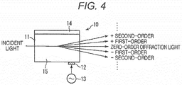
- Fig. 4 is a diagram showing the configuration of the AO device 10.
- Fig. 4 is a plan view of the AO device 10.
- the AO device (Acousto-optic device) 10 is made in such a way that a piezoelectric device 12 is bonded to an acousto-optic medium 11 that is formed of a single crystal such as tellurium dioxide (TeO2) or molybdate (PbMoO4), for example, and an acoustic absorbing material 14 is bonded to an opposite side of the acousto-optic medium 11 to the side where the piezoelectric device 12 is bonded.
- TeO2 tellurium dioxide
- PbMoO4 molybdate
- the AO device can deflect the laser beam in relation to time by controlling the waveform of an impressed voltage and scan the laser beam arbitrarily in one direction of a destination of the laser beam shone.
- the laser scanning unit 30 has the first AO device 10A, the second AO device 10B and the second AO device 10C.
- the first AO device 10A, the second AO device 10B and the second AO device 10C are disposed in series in the order of the first AO device 10A, the second AO device 10B and the second AO device 10C on an optical path L1 of the laser beam emitted from the light source unit 20.
- the first AO device 10A is disposed vertical to the acousto-optic medium 11 so that diffraction light of a laser beam incident thereon is diffused in the vertical direction (the U-D direction in Fig. 2 ).
- the second AO device 10B and the second AO device 10C are disposed in such a state that the first AO device 10A is rotated through 90 degrees relative to the laser optical path L1.
- the second AO devices 10B, 10C are disposed in such a state that the acousto-optic media 11 thereof lie horizontal so that diffraction light of a laser beam incident thereof is diffused in the horizontal direction (the L-R direction in Fig. 3 ).
- the first AO device 10A, the second OA device 10B and the second AO device 10C are fixed to the horizontal bracket 7a via predetermined support members.
- a laser beam that is incident on the first AO device 10A from the light source unit 20 is scanned in the vertical direction by the first AO device 10A and is incident on the second AO device 10B.
- the laser beam that is incident on the second AO device 10B from the first AO device 10A is scanned in the horizontal direction by the second AO device 10B and is incident on the second AO device 10C.
- the laser beam incident on the second AO device 10C from the second AO device 10B is scanned in the horizontal direction by the second AO device 10C and is emitted to the front of the vehicle.
- the laser beam from the light source unit 20 is diffused in the vertical direction by the first AO device 10A, the laser beam so diffused is then diffused two-dimensionally by the second AO device 10B, and the shining angle of the laser beam so diffused is then expanded further in the horizontal direction by the second AO device 10C, the laser beam eventually being emitted to the front of the vehicle.
- Fig. 5 is a block diagram illustrating the control unit.
- the control unit 40 is fixed to the lamp body 2, for example.
- the control unit 40 has a lamp ECU (Electronic Control Unit) 41, a ROM 42 and a RAM 43.
- the lamp ECU 41 has a light source control module 44 for controlling the light source unit 20 and a scan control module 45 for controlling the laser scanning unit 30.
- Various control programs are recorded in the ROM 42, and the lamp ECU 41 executes the control programs recorded in the ROM 42 in the RAM 43 to thereby generate various control signals.
- the light source control module 44 controls independently the illumination strengths of laser beams (R, G, B) emitted by the first light source 21R, the second light source 21G and the third light source 21B and the tuning on and off of the individual light sources.
- the scan control module 45 controls independently and individually frequencies oscillated by the alternating current oscillator 13 that is connected to the individual AO devices 10A, 10B and 10C.
- an image processor 54 a turn signal lamp switch 55, a steering operation detecting mechanism 56, an air bag signal detecting mechanism 57, a human sensor 58 and a grid shining switch 59 are connected to the lamp ECU 41.
- An onboard camera 52 and a road monitoring camera 53 are connected to the image processor 54.
- the onboard camera 52 includes a camera that is mounted on the subject vehicle or other vehicle to image the periphery of the vehicle in the form of a motion or still picture.
- the road monitoring camera 53 includes an intersection camera that is placed at an intersection and a monitoring camera that is placed in the vicinity of a road for imaging a road surface condition, a pedestrian, a vehicle such as a bicycle, a motorbike and a motor vehicle, an obstacle and the like in the form of a motion or still picture.
- the image processor 54 is connected to the road monitoring camera 53 via a communication line such as the Internet to obtain an image and image data picked up by the road monitoring camera 53.
- the image processor 54 images and the like that are picked up by the onboard camera 52 and the road monitoring camera 53 to the lamp ECU 41 as analyzed data.
- the control unit 40 also monitors whether or not the illumination strengths of the light sources 21R, 21G, 21B of the light source unit 20 are normal.
- Fig. 6A shows an example of a headlamp light distribution pattern.
- Fig. 6 is intended to illustrate a headlamp function of the vehicle lamp 1 and shows light distribution patterns that would be formed on an imaginary vertical screen set up in a position lying 25 meters ahead of the vehicle.
- the laser scanning unit 30 of the vehicle lamp 1 that is made up of the AO devices 10A, 10B and 10C can scan within a rectangular scanning area SA.
- the scanning area SA of the laser scanning unit 30 is a range that is defined, for example, by an upper end lying 10 degrees above an H-H line, a lower end lying 10 degrees below (-10 degrees) the H-H line, and left and right ends lying 10 degrees leftwards and rightwards ( ⁇ 10 degrees) of a V-V line and is set wider than an area where a low beam light distribution pattern PL is formed and an area where a high beam light distribution pattern PH is formed.
- the detailed shapes of the low beam light distribution pattern PL and the high beam light distribution pattern PH are known, and the description thereof will be omitted here.
- the control unit 40 when the scanning position of the laser scanning unit 30 lies within the low beam light distribution pattern PL, the control unit 40 combines respective laser beams of the first light source 21 R, the second light source 21G and the third light source 21B of the light source unit 20 to thereby emit a white laser beam.
- the control unit 40 stops the respective light sources 21R, 21G, 21 B of the light source unit 20 from outputting laser beams.
- a low beam light distribution pattern PL is formed which has an oncoming vehicle's side cut-off line CL1, a subject vehicle's side cut-off line CL2 and an oblique cut-off line CL3.
- the control unit 40 When the scanning position of the laser scanning unit 30 lies within the high beam light distribution pattern PH, the control unit 40 combines the respective laser beams of the light sources of the light source unit 20 to emit a white laser beam, while when the scanning position of the laser scanning unit 30 lies out of the high beam light distribution pattern PH, the control unit 40 stops the output of the light source unit 20.
- the control unit 40 strengthens the respective illumination strengths of the light sources 21R, 21G, 21B so as to be stronger than those when the low beam light distribution pattern PL is formed.
- the control unit 40 slows the scanning speed according to a designed luminous intensity of a hot zone.
- Figs. 6B to 6D show examples road surface shining light distribution patterns and illustrate a road surface shining function of the vehicle lamp 1.
- Fig. 6B shows an example in which a turning mark is shone on to the road surface
- Fig. 6C shows an example in which vehicle's width lines are shone on to the road surface
- Fig. 6D shows an example in which a driving assist grid lines are shone on to the road surface.
- the road surface shining function is a function to project a figure, symbol or character on to the road surface or a structure on the periphery of the vehicle.
- a turning mark 61 that indicates a left turn is drawn or shone in orange within the low beam light distribution pattern PL.
- the control unit 40 receives a signal from the turn signal lamp switch 55 or the steering operation detecting mechanism 56 at the lamp ECU 41 and controls so that the turning mark 61 is shone on to a predetermined position within the low beam light distribution pattern PL.
- the control unit 40 combines the laser beams of the respective light sources of the light source unit 20 to emit the white laser beam, while when the scanning position of the laser scanning unit 30 lies within the area where the turning mark 61 is to be formed, the control unit 40 combines the laser beams of the first light source 21R and the second light source 21G of the light source unit 20 to emit an orange laser beam.
- the control unit 40 stops the output of the light source unit 20.
- lines 62 indicating the vehicle's width are shone with white color onto a subject vehicle's driving lane.
- the control unit 40 controls so that the lines 62 that define therebetween a width that corresponds to the vehicle's width are shone on to the road surface in a traveling direction of the vehicle based on information regarding the width of the vehicle that is stored in the ROM 42 in advance.
- the control unit 40 combines the respective laser beams of the light sources of the light source unit 20 to emit a white laser beam, whereas when the scanning position of the laser scanning unit 30 lies out of the area where the lines 62 are to be shone, the control unit 40 stops the output of the light source unit 20.
- driving assist grid lines 63 are shone in blue within a low beam light distribution pattern PL.
- the control unit 40 receives a signal from the grid shining switch 59 disposed to, for example, driver's seat at the lamp ECU 41 and controls so that the grid lines 63 are shone within the low beam light distribution pattern PL.
- the control unit 40 combines the respective laser beams of the light sources of the light source unit 20 so as to emit a white laser beam.
- the control unit 40 controls the light source unit 20 so as to emit a blue laser beam from the third light source 21B.
- the control unit 40 stops the output of the light source unit 20.
- the turning mark 61, the lines 62 and the grid lines 63 represent the examples of the road surface shining light distribution patterns.
- the road surface shining light distribution patterns can also be formed when the low beam light distribution pattern PL (or the high beam light distribution pattern PH) is illuminated or is not illuminated and hence can be used in parallel with the headlamp light distribution patterns.
- the lines 62 and the grid lines 63 are shone on to the road surface when the low beam light distribution pattern PL (or the high beam light distribution pattern PH) is illuminated, a dark portion is formed so as to surround an outline of the figure shone to thereby make the figure conspicuous.
- the dark portion can be formed by strengthening the output of the third light source 21B more than those of the other color light sources by reducing or stopping the outputs of the other color light sources.
- the shining patterns described above represent the examples, and according to the vehicle lamp 1 of the first embodiment, a shining pattern in an arbitrary color can be shone in an arbitrary position within the scanning area SA that is projected ahead of the vehicle by combining together the turning on and off of the light source unit 20 that outputs RBB laser beams and the two-dimensional illumination by the laser scanning unit 30. Then, since the AO devices 10A, 10B, 10C are used as the laser scanning unit 30, the shining angle of laser beams can be controlled arbitrarily at high speeds using electric signals that are inputted into the respective AO devices 10A, 10B, 10C. Thus, even through vibrations and impacts are generated by a motor vehicle on which the vehicle lamp I is mounted, the shining angle of laser beams can be maintained accurately.
- the laser beams from the light source unit 20 are oscillated periodically in the first AO device 10A, the second AO device 10B and the second AO device 10C so as to change optical path lengths thereof, and therefore, speckle noise is suppressed in the vehicle lamp 1 in an ensured fashion.
- Fig. 7 is a front view of a vehicle lamp according to a second embodiment
- Fig. 8 is a vertical sectional view (a sectional view taken along a line VIII-VIII in Fig. 7 ) of the vehicle lamp
- Fig. 9 is a horizontal sectional view (a sectional view taken along a line IX-IX in Fig. 7 ) of the vehicle lamp.
- a vehicle lamp 1 of the second embodiment is similar to the vehicle lamp 1 of the first embodiment except for a configuration in which headlamp light distribution patterns are formed by, in place of the light source unit 20 and the laser scanning unit 30 of the first embodiment, a light source unit 200, a light source unit 100Hi having a laser scanning unit 300 and a light source unit 100Lo.
- a light source unit 200 a light source unit 200, a light source unit 100Hi having a laser scanning unit 300 and a light source unit 100Lo.
- Like reference numerals will be given to like configurations to those of the first embodiment, and a detailed description thereof will be omitted here.
- the vehicle lamp 1 of the second embodiment has the light source 200 that shines a laser beam and the light source unit (100Hi) having a light emitting portion (a luminous light emitting member 500) that emits light by receiving a laser beam from the light source unit 200, the laser scanning unit 300 having a single or plurality of acousto-optic devices that is disposed between the light source unit 200 and the light emitting portion 500 and which scans to the light emitting portion 500 the laser beam from the light source unit 200, and a projection lens 600 that is disposed in front of the light emitting portion 500.
- the light source unit 100Lo, a vertical bracket 7a, an extension 8 and aiming screws 9 are also provided win a lamp compartment of the vehicle lamp 1.
- the light source unit 100Lo is a so-called projector type light source unit and forms a low beam light distribution pattern PL.
- the light source unit 100Lo has an LED light source 71, a reflector 72, a shade 73 and a projection lens 74.
- An optical axis of the LED light source 71 is directed to the top of the lamp.
- the reflector 72 has a reflecting surface whose basic shape is based on an ellipsoidal plane and covers over the LED light source 71 in a semi-spherical fashion.
- the reflector 72 is fixed to the shade 73 so that a first focal point coincides substantially with the LED light source 71.
- the shade 73 is fixed to the vertical bracket 7a and formed cut-off lines CL1 to CL3.
- the projection lens 74 is fixed to a distal end of the shade 73 so that the projection lens 74 is disposed on an optical axis of the light source unit 100Lo and a rear focal point of the projection lens 74 coincides substantially with a second focal point of the reflector 72.
- the light source unit 100Lo may take other configurations as long as predetermined low beam light distribution pattern PL is formed.
- the light source unit 200 has an ultraviolet laser diode 201 that emits an ultraviolet laser beam, a collective lens 202 and the like, is disposed so as to be oriented to the rear of the lamp and obliquely upwards so that the shining direction of a laser beam coincides with the luminous light emitting member 500, and is fixed to a predetermined light source mounting portion (not shown).
- Figs. 7 to 9 shows an interior of the light source unit 200 as viewed through a casing thereof.
- a light source that is adopted in the light source unit 200 should be a light source that emits a blue or bluish violet laser beam.
- the laser scanning unit 300 has a first AO device 10A and a second AO device 10B. These AO devices are disposed in series in the order of the second AO device 10B and the first AO device 10A on an optical path L2 of a laser beam that is outputted from the light source unit 200.
- the second AO device 10B is disposed with an acousto-optic medium 11 made parallel to a laser optical path L2 so that diffraction light of an incident laser beam is diffused in a horizontal direction (directions indicated by arrows 1 and r in Fig. 9 ) on the laser optical path L2 and is fixed by a predetermined method.
- the first AO device 10A is disposed in such a way that the second AO device 10B is rotated through 90 degrees relative to the laser optical path L2.
- the first AO device 10A is disposed with an acousto-optic medium 11 made vertical to the laser optical path L2 so that diffraction light of an incident laser beam is diffused in a vertical direction (directions indicated by arrows u and d in Fig. 8 ) on the laser optical path L2 and is fixed by a predetermined method.
- An ultraviolet laser beam incident on the second AO device 10B from the light source unit 200 is scanned in the directions indicated by the arrows I and r and is then incident on the first AO device 10A.
- the ultraviolet laser beam that is incident on the first AO device 10A is scanned in the directions indicated by the arrows u and d and is emitted to the luminous light emitting member 500, which will be described later.
- a rectangular scanning area SA that is obtained in the laser scanning unit 300 is set so as to coincide with a position where luminescent elements 501 of the luminous light emitting member 500 are disposed.
- the luminous light emitting member 500 has a plurality of luminescent elements 501, a heat dissipating substrate 502 where the luminescent elements 501 are mounted and a shading frame body 503.
- the luminous light emitting member 500 is fixed to a front surface of the vertical bracket 7a in a position, which will be described later.
- the plurality of luminescent elements 501 are formed by dividing a single luminescent ceramic by the shading frame body 503, and the luminescent ceramic is divided into two rows that are aligned in a vertical direction and a plurality of (nine in this embodiment) columns that are aligned side by side in a horizontal direction.
- the luminescent ceramic is obtained by sintering a ceramic material that includes a red luminous light emitting element that converts, for example, the waveform of an ultraviolet laser beam into red light, a green luminous light emitting element that converts the waveform of the ultraviolet laser beam into green light and a blue luminous light emitting element that converts the waveform of the ultraviolet laser beam into blue light.
- the shading frame body 503 prevents light emitted from the individual luminous light emitting elements from being incident on the adjacent luminescent elements 501.
- the material of the luminescent element 501 is not limited to the ceramic, and hence, the luminescent element 501 may be formed of glass containing luminous light emitting materials or a transparent resin containing such luminous light emitting materials.
- the projection lens 600 is an aspheric planoconvex lens for which a front plane is convex and a rear plane is flat or a biconvex lens and reverts a light source image formed on a plane at a rear focal point F of the projection lens 600 for projection ahead of the vehicle.
- the luminous light emitting member 500 is disposed so that a central portion of the luminescent elements 501 in a lower row is positioned below the rear focal point F and a central portion of the luminescent materials 501 in an upper row coincides substantially with the rear focal point F.
- a control unit 40 has substantially the same configuration as that of the control unit 40 of the first embodiment. Like reference numerals will be given to like configurations, and the description thereof will be omitted here.
- a light source control module 44 controls the light source unit 200.
- a scan control module 45 controls the laser scanning unit 300. The light source control module 44 controls the turning on and off of the ultraviolet laser diode 201.
- the scan control module 45 controls device by device independently frequencies that are oscillated in an alternating current oscillator 13 that is connected to the AO devices 10A, 10B of the laser scanning unit 300.
- a program in which the positions of the luminescent elements 501 are associated with scanning angles of the laser scanning unit 300 is stored in a ROM 42 in advance.
- Fig. 10 shows an example of a headlamp light distribution pattern according to the second embodiment and shows light distribution patterns that would be formed on an imaginary vertical screen disposed 25 meters ahead of the vehicle.
- the light source unit 100Lo forms a low beam light distribution pattern PL having a known shape made up of an oblique cut-off line CL3 and a horizontal cut-offline CL1 on the imaginary vertical screen.
- the light source unit 100Hi forms a plurality of (nine in this embodiment) individual patterns P2 that are aligned in a horizontal direction in an area ranging from 6 degrees to 2 degrees above an H-H line and a plurality of (nine in this embodiment) individual patterns P3 that are aligned in the horizontal direction in an area ranging from 2 degrees above to 2 degrees (-2 degrees) below the H-H line, whereby the light source unit 100Hi can form a high beam light distribution pattern PH.
- the individual patterns P2 and P3 are projected images of the luminescent elements 501, and the individual patterns P2 correspond to the luminescent elements 501 in the lower row, while the individual patterns P3 correspond to the luminescent elements 501 in the upper row.
- a second individual pattern P3 from a right end in the high beam light distribution pattern PH (hereinafter, referred to as P3')
- P3' a second individual pattern from a right end in the high beam light distribution pattern PH
- P3' position information is sent from an image processor 54 to a lamp ECU 41.
- a luminescent element 501 that forms an individual pattern in a position that corresponds to the position information is identified, and a scanning angle of the laser scanning unit 300 that corresponds to the position information is also identified.
- the control unit 40 controls so that the light source unit 200 emits an ultraviolet laser beam, whereas the scanning position of the laser scanning unit 300 lies in an area of the luminescent element 501 that corresponds to the individual pattern P3', the control unit 40 controls so that the output of the light source unit 200 is stopped.
- This can form a headlamp light distribution pattern having a so-called ADB (Adaptive Driving Beam) function.
- the ABD function in which an ON and OFF control is executed at high speeds to provide a high visibility can be realized in the area where the high beam light distribution pattern is formed without involving any mechanical system by combining the turning on and off of the light source unit 200 that outputs the ultraviolet laser beam, the light deflection by the laser scanning unit 300 that includes the plurality of AO devices 10A, 10B and the luminous light emission by exciting the luminescent elements 501. Then, since the OA devices 10A, 10B are used as the laser scanning unit 300, even though vibrations and impacts are generated in a motor vehicle, the accuracy of the shining angle the laser scanning unit 300 can be maintained.
- the optical path length of the laser beam that is emitted from the light source unit 200 can be changed individually at the first AO device 10A and the second AO device 10B, and therefore, the generation of speckle noise in the vehicle lamp 1 is suppressed in an ensured fashion.
- a reflection preventive film is coated individually on surfaces 15 of the AO devices 10A, 10B, 10C (refer to Fig. 4 ) so as to reduce the surface reflection to thereby promote the transmission of the laser beam into the acousto-optic medium 11.
- control unit 40 has a fail safe function at the scan control module 45 so that the laser beam is emitted appropriately.
- the control unit 40 controls so that the frequencies that are inputted into the AO devices 10A, 10B, 10C are changed so as to cut off the laser beam.
- the control unit 40 controls so that the frequencies that are inputted into the AO devices 10A, 10B, 10C are changed to reduce the intensity of the laser beam so that the laser beam becomes, for example, a laser beam of a lower class that is specified under JISC 6802 that governs the "Emission Safety Standards for Laser Products" under the Japanese Industrial Standards or lower.
- the laser scanning unit 30 (the laser scanning unit 300) should have at least one AO device that diffuses the laser beam in the vertical direction and one AO device that diffuses the laser beam in the horizontal direction that are disposed on the laser optical path in a disordered fashion.
- at least two AO devices 10 may be disposed in series on the laser optical path in such a state that the AO devices 10 are rotated through 90 degrees relative to each other.
- the headlamp light distribution patterns are formed by the light source unit 20 and the laser scanning unit 30, it is preferable in consideration of the fact that the headlamp light distribution patterns are designed so as to be elongated horizontally in the vehicle's width direction that the laser scanning unit 30 is configured so as to diffuse the laser beam well in the horizontal direction.
- An example of this configuration is represented by the configuration of the first embodiment in which firstly, the first AO device 10-A that diffuses the laser beam in the vertical direction is disposed on the laser optical path L1 of the light source unit 20, and the plurality of second AO devices 10B, 10C that diffuse the laser beam in the horizontal direction are disposed ahead of the first AO device 10A so as to overlap the first AO device 10A.
Landscapes
- Physics & Mathematics (AREA)
- Engineering & Computer Science (AREA)
- General Engineering & Computer Science (AREA)
- Optics & Photonics (AREA)
- General Physics & Mathematics (AREA)
- Nonlinear Science (AREA)
- Mechanical Engineering (AREA)
- Non-Portable Lighting Devices Or Systems Thereof (AREA)
- Lighting Device Outwards From Vehicle And Optical Signal (AREA)
- Optical Modulation, Optical Deflection, Nonlinear Optics, Optical Demodulation, Optical Logic Elements (AREA)
Abstract
Description
- The present invention relates to a vehicle lamp and more particularly to a vehicle lamp including a laser scanning unit.
- Recently, vehicle lamps equipped with a laser scanning unit are known. In
Patent Literature 1, a laser beam is scanned using a laser scanning unit such as an MEMS (Micro Electro Mechanical Systems) mirror, a galvano-mirror or the like, so that a mark denoting a road sign is shone on to a road surface or the like. - Patent Literature 1:
JP-A-2013-125693 - However, in a laser scanning unit of a mechanical-optical system like the one described in
Patent Literature 1, a mechanical element becomes mandatory which oscillates an optical system vertically and horizontally. However, since a motor vehicle is subjected to vibrations at all times, there are fears that resonance is generated in the optical system of the laser scanning unit of the mechanical-optical system, this representing a problem in mounting the laser scanning unit on the motor vehicle. - The present invention has been made in view of the problem inherent in the prior art, and an object of the present invention is to provide a vehicle lamp including a laser scanning unit that is strong enough to deal with vibrations and which withstands the application to a motor vehicle.
- With a view to achieving the object, according to the present invention, there is provided a vehicle lamp including a light source that shines a laser beam and a laser canning unit having a single or a plurality of acousto-optic devices, wherein the laser scanning unit can control an angle at which a laser beam incident on the acousto-optic device is deflected.
- The acousto-optic device deflects incident light by generating a periodic change in refraction index in a highly anisotropic medium by applying an ultrasonic sound wave to the medium. Namely, by using the acousto-optic device as the laser scanning unit, the shining angle of the emitted laser beam can be controlled arbitrarily only by controlling an electric signal that is inputted into the acousto-optic device, and therefore, the vehicle lamp is obtained which is highly reliable in dealing with vibrations and impacts of a motor vehicle.
- It is possible to provide the vehicle lamp that includes the laser scanning unit that withstands the application to a motor vehicle.
-
-
Fig. 1 is a front view of a vehicle lamp according to a first embodiment of the present invention. -
Fig. 2 is a vertical sectional view of the vehicle lamp. -
Fig. 3 is a horizontal sectional view of the vehicle lamp. -
Fig. 4 is a diagram showing the configuration of an AO device. -
Fig. 5 is a block diagram depicting a control unit. -
Fig. 6A shows an example of a headlamp light distribution pattern according to the first embodiment. -
Fig. 6B shows an example in which a turning mark is shone on to the road surface. -
Fig. 6C shows an example in which vehicle's width lines are shone on to the road surface. -
Fig. 6D shows an example in which a driving assist grid of lines is shown on to the road surface. -
Fig. 7 is a front view of a vehicle lamp according to a second embodiment of the present invention. -
Fig. 8 is a vertical sectional view of the vehicle lamp. -
Fig. 9 is a horizontal sectional view of the vehicle lamp. -
Fig. 10 shows an example of a headlamp light distribution pattern according to the second embodiment. - Next, preferred embodiments of the present invention will be described by reference to the drawings.
-
Fig. 1 is a front view of a vehicle lamp according to a first embodiment of the present invention,Fig. 2 is a vertical sectional view (a sectional view taken along a line II-II inFig. 1 ) of the vehicle lamp, andFig. 3 is a horizontal sectional view (a sectional view taken along a line III-III inFig. 1 ) of the vehicle lamp. - A
vehicle lamp 1 shown in the figures represents a headlamp that is provided either on the left or right of a front portion of a vehicle. Thevehicle lamp 1 has a lamp compartment that is defined by a box-shaped lamp body 2 having an opening portion and afront cover 4 that is formed of transparent resin or glass for attachment to the opening portion. In the figures, an arrow F denotes the front of the lamp, an arrow B denotes the rear of the lamp, an arrow L denotes the left of the lamp, an arrow R denotes the right of the lamp, an arrow U denotes the top of the lamp, and an arrow D denotes the bottom of the lamp. Arrows with no reference character denote traveling directions of rays of light. - The vehicle lamp 1 (or the lamp compartment thereof) has, as will be described later, a
light source unit 20 that shines a laser beam, alaser scanning unit 30 having a first acousto-optic device that scans a laser beam from the light source in one direction of a destination of a laser beam shone from the light source and a second acousto-optic device that scans a laser beam from the light source in the other direction that intersects the one direction at right angles, and acontrol unit 40. In addition to these constituent parts, avertical bracket 7a and ahorizontal bracket 7b are provided in the lamp compartment of thevehicle lamp 1 as support members that support thelight source unit 20 and thelaser scanning unit 30. Anextension 8, which acts as a concealing member, is provided at a front portion within the lamp compartment of thevehicle lamp 1, and thisextension 8 has anopening portion 8a that permits light emerging from thelaser scanning unit 30 to travel to the front of the lamp. - The
vertical bracket 7a and thehorizontal bracket 7b are formed of a metal having a high thermal conductivity such as aluminum so that heat generated by thelight source unit 20 is dissipated with good efficiency. Thevertical bracket 7a is fixed to thelamp body 2 at three locations of its corner portions with aimingscrews 9. Thehorizontal bracket 7b is fixed to a front surface of thevertical bracket 7a. In the vehicle lamp I, optical axes of thelight source unit 20 and thelaser scanning unit 30 can be adjusted vertically and horizontally by adjusting the posture of thevertical bracket 7a by rotating the aimingscrews 9. - The
light source unit 20 is a so-called RGB laser unit and has afirst light source 21 R that is a red laser diode, asecond light source 21G that is a green laser diode, athird light source 21B that is a blue laser diode, substrates for these light sources, lenses that make light emitted from thelight sources collective lens 25 that is provided in a casing of thelight source unit 20, and thecollective lens 25 that collects the reflected light from the dichroic mirrors for emission from thelight source unit 20.Figs. 2 and3 show an interior of the casing of thelight source unit 20 as viewed through the casing. In addition to the constituent parts described, thelight source unit 20 has amonitoring unit 26 that controls the outputs of thelight sources light source unit 20 is fixed to thevertical bracket 7a and thehorizontal bracket 7b so that thecollective lens 25 is positioned at the front of the casing. - The
laser scanning unit 30 has a plurality of acousto-optic devices (hereinafter, referred to as AO device) 10A, 10a, 10C. Since theAO devices AO device 10 that generally represents theAO devices -
Fig. 4 is a diagram showing the configuration of theAO device 10.Fig. 4 is a plan view of theAO device 10. The AO device (Acousto-optic device) 10 is made in such a way that apiezoelectric device 12 is bonded to an acousto-optic medium 11 that is formed of a single crystal such as tellurium dioxide (TeO2) or molybdate (PbMoO4), for example, and an acoustic absorbingmaterial 14 is bonded to an opposite side of the acousto-optic medium 11 to the side where thepiezoelectric device 12 is bonded. When an electric signal is applied to thepiezoelectric device 12 from an alternatingcurrent oscillator 13, an ultrasonic sound wave is propagated to the interior of the acousto-optic medium 11. Then, when a laser beam is transmitted through the acousto-optic medium 11 where the ultrasonic sound wave is propagated, the laser beam causes an anisotropic Bragg diffraction by making use of the anisotropy of the acousto-optic medium 11 and is then divided into diffraction light ranging about zero-order diffraction light into first-order, second-order, .. , x-order diffraction light on one side and -first-order, -second-order, .., -x-order diffraction light on the other side. Namely, the AO device can deflect the laser beam in relation to time by controlling the waveform of an impressed voltage and scan the laser beam arbitrarily in one direction of a destination of the laser beam shone. - The
laser scanning unit 30 has thefirst AO device 10A, thesecond AO device 10B and the second AO device 10C. Thefirst AO device 10A, thesecond AO device 10B and the second AO device 10C are disposed in series in the order of thefirst AO device 10A, thesecond AO device 10B and the second AO device 10C on an optical path L1 of the laser beam emitted from thelight source unit 20. - The
first AO device 10A is disposed vertical to the acousto-optic medium 11 so that diffraction light of a laser beam incident thereon is diffused in the vertical direction (the U-D direction inFig. 2 ). Thesecond AO device 10B and the second AO device 10C are disposed in such a state that thefirst AO device 10A is rotated through 90 degrees relative to the laser optical path L1. Namely, thesecond AO devices 10B, 10C are disposed in such a state that the acousto-optic media 11 thereof lie horizontal so that diffraction light of a laser beam incident thereof is diffused in the horizontal direction (the L-R direction inFig. 3 ). Thefirst AO device 10A, thesecond OA device 10B and the second AO device 10C are fixed to thehorizontal bracket 7a via predetermined support members. - A laser beam that is incident on the
first AO device 10A from thelight source unit 20 is scanned in the vertical direction by thefirst AO device 10A and is incident on thesecond AO device 10B. The laser beam that is incident on thesecond AO device 10B from thefirst AO device 10A is scanned in the horizontal direction by thesecond AO device 10B and is incident on the second AO device 10C. The laser beam incident on the second AO device 10C from thesecond AO device 10B is scanned in the horizontal direction by the second AO device 10C and is emitted to the front of the vehicle. Namely, the laser beam from thelight source unit 20 is diffused in the vertical direction by thefirst AO device 10A, the laser beam so diffused is then diffused two-dimensionally by thesecond AO device 10B, and the shining angle of the laser beam so diffused is then expanded further in the horizontal direction by the second AO device 10C, the laser beam eventually being emitted to the front of the vehicle. - Next, referring to
Fig. 5 , thecontrol unit 40 will be described.Fig. 5 is a block diagram illustrating the control unit. Thecontrol unit 40 is fixed to thelamp body 2, for example. Thecontrol unit 40 has a lamp ECU (Electronic Control Unit) 41, aROM 42 and aRAM 43. Thelamp ECU 41 has a lightsource control module 44 for controlling thelight source unit 20 and ascan control module 45 for controlling thelaser scanning unit 30. Various control programs are recorded in theROM 42, and thelamp ECU 41 executes the control programs recorded in theROM 42 in theRAM 43 to thereby generate various control signals. The lightsource control module 44 controls independently the illumination strengths of laser beams (R, G, B) emitted by the firstlight source 21R, the secondlight source 21G and the thirdlight source 21B and the tuning on and off of the individual light sources. Thescan control module 45 controls independently and individually frequencies oscillated by the alternatingcurrent oscillator 13 that is connected to theindividual AO devices - In addition, an
image processor 54, a turnsignal lamp switch 55, a steeringoperation detecting mechanism 56, an air bagsignal detecting mechanism 57, ahuman sensor 58 and agrid shining switch 59 are connected to thelamp ECU 41. Anonboard camera 52 and aroad monitoring camera 53 are connected to theimage processor 54. Theonboard camera 52 includes a camera that is mounted on the subject vehicle or other vehicle to image the periphery of the vehicle in the form of a motion or still picture. Theroad monitoring camera 53 includes an intersection camera that is placed at an intersection and a monitoring camera that is placed in the vicinity of a road for imaging a road surface condition, a pedestrian, a vehicle such as a bicycle, a motorbike and a motor vehicle, an obstacle and the like in the form of a motion or still picture. Theimage processor 54 is connected to theroad monitoring camera 53 via a communication line such as the Internet to obtain an image and image data picked up by theroad monitoring camera 53. Theimage processor 54 images and the like that are picked up by theonboard camera 52 and theroad monitoring camera 53 to thelamp ECU 41 as analyzed data. Thecontrol unit 40 also monitors whether or not the illumination strengths of thelight sources light source unit 20 are normal. - Referring to
Figs. 6A to 6D , light distribution patterns or shining patterns that can be formed by thevehicle lamp 1 configured as described above will be described. -
Fig. 6A shows an example of a headlamp light distribution pattern.Fig. 6 is intended to illustrate a headlamp function of thevehicle lamp 1 and shows light distribution patterns that would be formed on an imaginary vertical screen set up in a position lying 25 meters ahead of the vehicle. Thelaser scanning unit 30 of thevehicle lamp 1 that is made up of theAO devices laser scanning unit 30 is a range that is defined, for example, by an upper end lying 10 degrees above an H-H line, a lower end lying 10 degrees below (-10 degrees) the H-H line, and left and right ends lying 10 degrees leftwards and rightwards (±10 degrees) of a V-V line and is set wider than an area where a low beam light distribution pattern PL is formed and an area where a high beam light distribution pattern PH is formed. The detailed shapes of the low beam light distribution pattern PL and the high beam light distribution pattern PH are known, and the description thereof will be omitted here. - Specifically, as shown in
Fig. 6A , in the case of the low beam light distribution pattern PL being formed, when the scanning position of thelaser scanning unit 30 lies within the low beam light distribution pattern PL, thecontrol unit 40 combines respective laser beams of thefirst light source 21 R, the secondlight source 21G and the thirdlight source 21B of thelight source unit 20 to thereby emit a white laser beam. When the scanning position of thelaser scanning unit 30 lies out of the low beam light distribution pattern PL, thecontrol unit 40 stops therespective light sources light source unit 20 from outputting laser beams. As a result of this, a low beam light distribution pattern PL is formed which has an oncoming vehicle's side cut-off line CL1, a subject vehicle's side cut-off line CL2 and an oblique cut-off line CL3. - Although an illustration is omitted, this will be true with the formation of the high beam light distribution pattern PH. When the scanning position of the
laser scanning unit 30 lies within the high beam light distribution pattern PH, thecontrol unit 40 combines the respective laser beams of the light sources of thelight source unit 20 to emit a white laser beam, while when the scanning position of thelaser scanning unit 30 lies out of the high beam light distribution pattern PH, thecontrol unit 40 stops the output of thelight source unit 20. When forming the high beam light distribution pattern PH, thecontrol unit 40 strengthens the respective illumination strengths of thelight sources control unit 40 slows the scanning speed according to a designed luminous intensity of a hot zone. -
Figs. 6B to 6D show examples road surface shining light distribution patterns and illustrate a road surface shining function of thevehicle lamp 1.Fig. 6B shows an example in which a turning mark is shone on to the road surface,Fig. 6C shows an example in which vehicle's width lines are shone on to the road surface, andFig. 6D shows an example in which a driving assist grid lines are shone on to the road surface. The road surface shining function is a function to project a figure, symbol or character on to the road surface or a structure on the periphery of the vehicle. - In
Fig. 6B , a turningmark 61 that indicates a left turn is drawn or shone in orange within the low beam light distribution pattern PL. In this case, thecontrol unit 40 receives a signal from the turnsignal lamp switch 55 or the steeringoperation detecting mechanism 56 at thelamp ECU 41 and controls so that the turningmark 61 is shone on to a predetermined position within the low beam light distribution pattern PL. Specifically, when the scanning position of thelaser scanning unit 30 lies within the low beam light distribution pattern PL, thecontrol unit 40 combines the laser beams of the respective light sources of thelight source unit 20 to emit the white laser beam, while when the scanning position of thelaser scanning unit 30 lies within the area where the turningmark 61 is to be formed, thecontrol unit 40 combines the laser beams of the firstlight source 21R and the secondlight source 21G of thelight source unit 20 to emit an orange laser beam. When the scanning position of thelaser scanning unit 30 lies in neither of the areas described above, thecontrol unit 40 stops the output of thelight source unit 20. - In
Fig. 6C ,lines 62 indicating the vehicle's width are shone with white color onto a subject vehicle's driving lane. In this case, thecontrol unit 40 controls so that thelines 62 that define therebetween a width that corresponds to the vehicle's width are shone on to the road surface in a traveling direction of the vehicle based on information regarding the width of the vehicle that is stored in theROM 42 in advance. Specifically, when the scanning position of thelaser scanning unit 30 lies within an area where thelines 62 are to be shone, thecontrol unit 40 combines the respective laser beams of the light sources of thelight source unit 20 to emit a white laser beam, whereas when the scanning position of thelaser scanning unit 30 lies out of the area where thelines 62 are to be shone, thecontrol unit 40 stops the output of thelight source unit 20. - In
Fig. 6D , driving assistgrid lines 63 are shone in blue within a low beam light distribution pattern PL. In this case, thecontrol unit 40 receives a signal from thegrid shining switch 59 disposed to, for example, driver's seat at thelamp ECU 41 and controls so that thegrid lines 63 are shone within the low beam light distribution pattern PL. When the scanning position of thelaser scanning unit 30 lies within the low beam light distribution pattern PL, thecontrol unit 40 combines the respective laser beams of the light sources of thelight source unit 20 so as to emit a white laser beam. On the other hand, when the scanning position of thelaser scanning unit 30 lies within an area where thegrid lines 63 are to be formed, thecontrol unit 40 controls thelight source unit 20 so as to emit a blue laser beam from the thirdlight source 21B. When the scanning position of thelaser scanning unit 30 lies in neither of the two areas described above, thecontrol unit 40 stops the output of thelight source unit 20. - The turning
mark 61, thelines 62 and thegrid lines 63 represent the examples of the road surface shining light distribution patterns. In addition, the road surface shining light distribution patterns can also be formed when the low beam light distribution pattern PL (or the high beam light distribution pattern PH) is illuminated or is not illuminated and hence can be used in parallel with the headlamp light distribution patterns. In the event that turningmark 61, thelines 62 and thegrid lines 63 are shone on to the road surface when the low beam light distribution pattern PL (or the high beam light distribution pattern PH) is illuminated, a dark portion is formed so as to surround an outline of the figure shone to thereby make the figure conspicuous. When describing this specifically by taking, for example, although thelaser scanning unit 30 is scanned with the illumination strengths of therespective light sources light source unit 20 made equal to one another at a time corresponding to a location where the low beam light distribution pattern PL is formed, at a time corresponding to a location where thegrid lines 63 are wanted to be shone, the dark portion can be formed by strengthening the output of the thirdlight source 21B more than those of the other color light sources by reducing or stopping the outputs of the other color light sources. - The shining patterns described above represent the examples, and according to the
vehicle lamp 1 of the first embodiment, a shining pattern in an arbitrary color can be shone in an arbitrary position within the scanning area SA that is projected ahead of the vehicle by combining together the turning on and off of thelight source unit 20 that outputs RBB laser beams and the two-dimensional illumination by thelaser scanning unit 30. Then, since theAO devices laser scanning unit 30, the shining angle of laser beams can be controlled arbitrarily at high speeds using electric signals that are inputted into therespective AO devices light source unit 20 are oscillated periodically in thefirst AO device 10A, thesecond AO device 10B and the second AO device 10C so as to change optical path lengths thereof, and therefore, speckle noise is suppressed in thevehicle lamp 1 in an ensured fashion. -
Fig. 7 is a front view of a vehicle lamp according to a second embodiment,Fig. 8 is a vertical sectional view (a sectional view taken along a line VIII-VIII inFig. 7 ) of the vehicle lamp, andFig. 9 is a horizontal sectional view (a sectional view taken along a line IX-IX inFig. 7 ) of the vehicle lamp. - A
vehicle lamp 1 of the second embodiment is similar to thevehicle lamp 1 of the first embodiment except for a configuration in which headlamp light distribution patterns are formed by, in place of thelight source unit 20 and thelaser scanning unit 30 of the first embodiment, alight source unit 200, a light source unit 100Hi having alaser scanning unit 300 and a light source unit 100Lo. Like reference numerals will be given to like configurations to those of the first embodiment, and a detailed description thereof will be omitted here. - As will be described later, the
vehicle lamp 1 of the second embodiment has thelight source 200 that shines a laser beam and the light source unit (100Hi) having a light emitting portion (a luminous light emitting member 500) that emits light by receiving a laser beam from thelight source unit 200, thelaser scanning unit 300 having a single or plurality of acousto-optic devices that is disposed between thelight source unit 200 and thelight emitting portion 500 and which scans to thelight emitting portion 500 the laser beam from thelight source unit 200, and aprojection lens 600 that is disposed in front of thelight emitting portion 500. In addition to these constituent parts, the light source unit 100Lo, avertical bracket 7a, anextension 8 and aimingscrews 9 are also provided win a lamp compartment of thevehicle lamp 1. - The light source unit 100Lo is a so-called projector type light source unit and forms a low beam light distribution pattern PL. The light source unit 100Lo has an
LED light source 71, areflector 72, ashade 73 and aprojection lens 74. An optical axis of theLED light source 71 is directed to the top of the lamp. Thereflector 72 has a reflecting surface whose basic shape is based on an ellipsoidal plane and covers over theLED light source 71 in a semi-spherical fashion. Thereflector 72 is fixed to theshade 73 so that a first focal point coincides substantially with theLED light source 71. Theshade 73 is fixed to thevertical bracket 7a and formed cut-off lines CL1 to CL3. Theprojection lens 74 is fixed to a distal end of theshade 73 so that theprojection lens 74 is disposed on an optical axis of the light source unit 100Lo and a rear focal point of theprojection lens 74 coincides substantially with a second focal point of thereflector 72. The light source unit 100Lo may take other configurations as long as predetermined low beam light distribution pattern PL is formed. - Next, the light source unit 10OHi will be described. The
light source unit 200 has anultraviolet laser diode 201 that emits an ultraviolet laser beam, acollective lens 202 and the like, is disposed so as to be oriented to the rear of the lamp and obliquely upwards so that the shining direction of a laser beam coincides with the luminouslight emitting member 500, and is fixed to a predetermined light source mounting portion (not shown).Figs. 7 to 9 shows an interior of thelight source unit 200 as viewed through a casing thereof. A light source that is adopted in thelight source unit 200 should be a light source that emits a blue or bluish violet laser beam. - The
laser scanning unit 300 has afirst AO device 10A and asecond AO device 10B. These AO devices are disposed in series in the order of thesecond AO device 10B and thefirst AO device 10A on an optical path L2 of a laser beam that is outputted from thelight source unit 200. - The
second AO device 10B is disposed with an acousto-optic medium 11 made parallel to a laser optical path L2 so that diffraction light of an incident laser beam is diffused in a horizontal direction (directions indicated byarrows 1 and r inFig. 9 ) on the laser optical path L2 and is fixed by a predetermined method. Thefirst AO device 10A is disposed in such a way that thesecond AO device 10B is rotated through 90 degrees relative to the laser optical path L2. Namely, thefirst AO device 10A is disposed with an acousto-optic medium 11 made vertical to the laser optical path L2 so that diffraction light of an incident laser beam is diffused in a vertical direction (directions indicated by arrows u and d inFig. 8 ) on the laser optical path L2 and is fixed by a predetermined method. - An ultraviolet laser beam incident on the
second AO device 10B from thelight source unit 200 is scanned in the directions indicated by the arrows I and r and is then incident on thefirst AO device 10A. The ultraviolet laser beam that is incident on thefirst AO device 10A is scanned in the directions indicated by the arrows u and d and is emitted to the luminouslight emitting member 500, which will be described later. A rectangular scanning area SA that is obtained in thelaser scanning unit 300 is set so as to coincide with a position whereluminescent elements 501 of the luminouslight emitting member 500 are disposed. - The luminous
light emitting member 500 has a plurality ofluminescent elements 501, aheat dissipating substrate 502 where theluminescent elements 501 are mounted and ashading frame body 503. The luminouslight emitting member 500 is fixed to a front surface of thevertical bracket 7a in a position, which will be described later. - The plurality of
luminescent elements 501 are formed by dividing a single luminescent ceramic by theshading frame body 503, and the luminescent ceramic is divided into two rows that are aligned in a vertical direction and a plurality of (nine in this embodiment) columns that are aligned side by side in a horizontal direction. The luminescent ceramic is obtained by sintering a ceramic material that includes a red luminous light emitting element that converts, for example, the waveform of an ultraviolet laser beam into red light, a green luminous light emitting element that converts the waveform of the ultraviolet laser beam into green light and a blue luminous light emitting element that converts the waveform of the ultraviolet laser beam into blue light. Theshading frame body 503 prevents light emitted from the individual luminous light emitting elements from being incident on the adjacentluminescent elements 501. The material of theluminescent element 501 is not limited to the ceramic, and hence, theluminescent element 501 may be formed of glass containing luminous light emitting materials or a transparent resin containing such luminous light emitting materials. - The
projection lens 600 is an aspheric planoconvex lens for which a front plane is convex and a rear plane is flat or a biconvex lens and reverts a light source image formed on a plane at a rear focal point F of theprojection lens 600 for projection ahead of the vehicle. The luminouslight emitting member 500 is disposed so that a central portion of theluminescent elements 501 in a lower row is positioned below the rear focal point F and a central portion of theluminescent materials 501 in an upper row coincides substantially with the rear focal point F. - A
control unit 40 has substantially the same configuration as that of thecontrol unit 40 of the first embodiment. Like reference numerals will be given to like configurations, and the description thereof will be omitted here. A lightsource control module 44 controls thelight source unit 200. Ascan control module 45 controls thelaser scanning unit 300. The lightsource control module 44 controls the turning on and off of theultraviolet laser diode 201. Thescan control module 45 controls device by device independently frequencies that are oscillated in an alternatingcurrent oscillator 13 that is connected to theAO devices laser scanning unit 300. A program in which the positions of theluminescent elements 501 are associated with scanning angles of thelaser scanning unit 300 is stored in aROM 42 in advance. - Headlamp light distribution patterns that are formed by the
vehicle lamp 1 configured in the way described above will be described.Fig. 10 shows an example of a headlamp light distribution pattern according to the second embodiment and shows light distribution patterns that would be formed on an imaginary vertical screen disposed 25 meters ahead of the vehicle. The light source unit 100Lo forms a low beam light distribution pattern PL having a known shape made up of an oblique cut-off line CL3 and a horizontal cut-offline CL1 on the imaginary vertical screen. - The light source unit 100Hi forms a plurality of (nine in this embodiment) individual patterns P2 that are aligned in a horizontal direction in an area ranging from 6 degrees to 2 degrees above an H-H line and a plurality of (nine in this embodiment) individual patterns P3 that are aligned in the horizontal direction in an area ranging from 2 degrees above to 2 degrees (-2 degrees) below the H-H line, whereby the light source unit 100Hi can form a high beam light distribution pattern PH. The individual patterns P2 and P3 are projected images of the
luminescent elements 501, and the individual patterns P2 correspond to theluminescent elements 501 in the lower row, while the individual patterns P3 correspond to theluminescent elements 501 in the upper row. - Specifically, as shown in
Fig. 10 , in the event that an oncoming vehicle or a pedestrian exists in a position that corresponds the a second individual pattern P3 from a right end in the high beam light distribution pattern PH (hereinafter, referred to as P3'), they are detected by anonboard camera 52 or aroad monitoring camera 53, and position information is sent from animage processor 54 to alamp ECU 41. In thelamp ECU 41, aluminescent element 501 that forms an individual pattern in a position that corresponds to the position information is identified, and a scanning angle of thelaser scanning unit 300 that corresponds to the position information is also identified. - When the scanning position of the
laser scanning unit 300 lies within areas ofluminescent elements 501 that correspond to the divisions other than that of the individual pattern P3', thecontrol unit 40 controls so that thelight source unit 200 emits an ultraviolet laser beam, whereas the scanning position of thelaser scanning unit 300 lies in an area of theluminescent element 501 that corresponds to the individual pattern P3', thecontrol unit 40 controls so that the output of thelight source unit 200 is stopped. This can form a headlamp light distribution pattern having a so-called ADB (Adaptive Driving Beam) function. - Namely, according to the
vehicle lamp 1 of the second embodiment, the ABD function in which an ON and OFF control is executed at high speeds to provide a high visibility can be realized in the area where the high beam light distribution pattern is formed without involving any mechanical system by combining the turning on and off of thelight source unit 200 that outputs the ultraviolet laser beam, the light deflection by thelaser scanning unit 300 that includes the plurality ofAO devices luminescent elements 501. Then, since theOA devices laser scanning unit 300, even though vibrations and impacts are generated in a motor vehicle, the accuracy of the shining angle thelaser scanning unit 300 can be maintained. In addition, the optical path length of the laser beam that is emitted from thelight source unit 200 can be changed individually at thefirst AO device 10A and thesecond AO device 10B, and therefore, the generation of speckle noise in thevehicle lamp 1 is suppressed in an ensured fashion. - In the embodiments, it is preferable that a reflection preventive film is coated individually on
surfaces 15 of theAO devices Fig. 4 ) so as to reduce the surface reflection to thereby promote the transmission of the laser beam into the acousto-optic medium 11. - In addition, in the embodiments, it is preferable that the
control unit 40 has a fail safe function at thescan control module 45 so that the laser beam is emitted appropriately. For example, when a signal from the air bagsignal detecting mechanism 57 is detected as a result of an occurrence of an accident, thecontrol unit 40 controls so that the frequencies that are inputted into theAO devices human sensor 58 is detected, thecontrol unit 40 controls so that the frequencies that are inputted into theAO devices - In the embodiments, from the viewpoint of achieving the two-dimensional illumination, the laser scanning unit 30 (the laser scanning unit 300) should have at least one AO device that diffuses the laser beam in the vertical direction and one AO device that diffuses the laser beam in the horizontal direction that are disposed on the laser optical path in a disordered fashion. Namely, at least two
AO devices 10 may be disposed in series on the laser optical path in such a state that theAO devices 10 are rotated through 90 degrees relative to each other. - Although there is a limit on the range where a laser beam is refracted by one
AO device 10, in case a plurality of AO devices are disposed on an optical path of incident light in the same position so as to overlap each other in series, light that passes through oneAO device 10 is refracted again by anotherAO device 10 that is disposed ahead of the oneAO device 10, and therefore, the scanning range is expanded in the one direction in which the AO devices are overlapped. Consequently, in the event that the headlamp light distribution patterns are formed by thelight source unit 20 and thelaser scanning unit 30, it is preferable in consideration of the fact that the headlamp light distribution patterns are designed so as to be elongated horizontally in the vehicle's width direction that thelaser scanning unit 30 is configured so as to diffuse the laser beam well in the horizontal direction. An example of this configuration is represented by the configuration of the first embodiment in which firstly, the first AO device 10-A that diffuses the laser beam in the vertical direction is disposed on the laser optical path L1 of thelight source unit 20, and the plurality ofsecond AO devices 10B, 10C that diffuse the laser beam in the horizontal direction are disposed ahead of thefirst AO device 10A so as to overlap thefirst AO device 10A. - However, there should be various modified examples in relation to the number of
AO devices 10 that thelaser scanning unit 30 includes and the order in which theAO devices 10 are disposed. Namely, a configuration may be adopted in which asingle AO device 10 is used or in which the number of AO devices that diffuse the laser beam in the vertical direction is greater than the number of AO devices that diffuse the laser beam in the horizontal direction. - The present invention has been described in detail and by reference to the specific embodiments. However, it is obvious to those skilled in the art to which the present invention pertains that various alterations and/or modifications can be made thereto without departing from the spirit and scope of the present invention.
- This patent application is based on
Japanese Patent Application No. 2014-084816 -
- 1: vehicle lamp; 10A; first AO device; 10B; second AO device; 10C: third AO device; 20 (200): light source unit; 30 (300): laser scanning unit; 40: control unit; 100Hi: light source unit; 500 luminous light emitting member; 600: projection lens
Claims (1)
- A vehicle lamp comprising:a light source that shines a laser beam; anda laser scanning unit having a single or plurality of acousto-optic devices,wherein
the laser scanning unit can control an angle at which a laser beam incident on the acousto-optic device is deflected.
Applications Claiming Priority (2)
| Application Number | Priority Date | Filing Date | Title |
|---|---|---|---|
| JP2014084816A JP6411771B2 (en) | 2014-04-16 | 2014-04-16 | Vehicle lighting |
| PCT/JP2015/060889 WO2015159764A1 (en) | 2014-04-16 | 2015-04-07 | Vehicular lighting equipment |
Publications (2)
| Publication Number | Publication Date |
|---|---|
| EP3133336A1 true EP3133336A1 (en) | 2017-02-22 |
| EP3133336A4 EP3133336A4 (en) | 2017-11-29 |
Family
ID=54323975
Family Applications (1)
| Application Number | Title | Priority Date | Filing Date |
|---|---|---|---|
| EP15779843.0A Withdrawn EP3133336A4 (en) | 2014-04-16 | 2015-04-07 | Vehicular lighting equipment |
Country Status (5)
| Country | Link |
|---|---|
| US (1) | US10551020B2 (en) |
| EP (1) | EP3133336A4 (en) |
| JP (1) | JP6411771B2 (en) |
| CN (1) | CN106233066B (en) |
| WO (1) | WO2015159764A1 (en) |
Cited By (3)
| Publication number | Priority date | Publication date | Assignee | Title |
|---|---|---|---|---|
| WO2019086176A1 (en) * | 2017-11-02 | 2019-05-09 | Bayerische Motoren Werke Aktiengesellschaft | Lighting device for a motor vehicle |
| EP3283816B1 (en) * | 2015-04-16 | 2020-03-25 | ZKW Group GmbH | Illumination apparatus for a motor vehicle |
| US11060681B2 (en) | 2017-11-02 | 2021-07-13 | Bayerische Motoren Werke Aktiengesellschaft | Lighting apparatus for a motor vehicle |
Families Citing this family (15)
| Publication number | Priority date | Publication date | Assignee | Title |
|---|---|---|---|---|
| JP3502958B2 (en) | 1994-05-16 | 2004-03-02 | 国土総合建設株式会社 | Ground improvement method |
| FR3036162B1 (en) * | 2015-05-13 | 2017-06-16 | Valeo Vision | LIGHTING MODULE BIFUNCTION CODE - ROAD FOR MOTOR VEHICLE |
| JP6520636B2 (en) | 2015-10-16 | 2019-05-29 | 株式会社デンソー | Physical quantity sensor subassembly and physical quantity measuring device |
| DE102016102446A1 (en) * | 2016-02-12 | 2017-08-17 | Hella Kgaa Hueck & Co. | Lighting device for vehicles |
| FR3056682B1 (en) * | 2016-09-27 | 2020-10-16 | Valeo Vision | LIGHT SOURCE SUPPORT WITH A REFERENCING ELEMENT SPREADING INTO TWO AXES |
| JP6761600B2 (en) * | 2017-01-05 | 2020-09-30 | 大日本印刷株式会社 | Lighting device |
| DE102017203889A1 (en) | 2017-03-09 | 2018-09-13 | Bayerische Motoren Werke Aktiengesellschaft | Lighting device for a motor vehicle |
| JP6956513B2 (en) * | 2017-04-26 | 2021-11-02 | 株式会社小糸製作所 | Motor drive circuit and vehicle lighting |
| JP7092123B2 (en) * | 2017-05-22 | 2022-06-28 | 大日本印刷株式会社 | Lighting equipment |
| DE102018102575B4 (en) * | 2017-05-25 | 2024-03-07 | Hasco Vision Technology Co., Ltd. | Intelligent multi-function automotive headlight module |
| DE102017122213A1 (en) * | 2017-09-26 | 2019-03-28 | HELLA GmbH & Co. KGaA | Lighting device for vehicles |
| JP7007868B2 (en) * | 2017-11-14 | 2022-01-25 | 株式会社小糸製作所 | Aiming adjustment mechanism for vehicle headlights and vehicle headlights |
| FR3079467A1 (en) * | 2018-04-03 | 2019-10-04 | Valeo Vision | MONOLITHIC MATRIX LUMINOUS DEVICE OF A MOTOR VEHICLE FOR WRITING ON THE GROUND |
| CN110805876B (en) * | 2018-08-03 | 2022-03-15 | 株式会社小糸制作所 | Vehicle headlamp |
| CN112368510B (en) * | 2018-08-21 | 2022-10-11 | 株式会社小糸制作所 | Vehicle lamp |
Family Cites Families (14)
| Publication number | Priority date | Publication date | Assignee | Title |
|---|---|---|---|---|
| US3514534A (en) * | 1966-12-09 | 1970-05-26 | Zenith Radio Corp | Wide-aperture laser beam modulating and scanning system |
| US4225938A (en) * | 1978-12-05 | 1980-09-30 | The United States Of America As Represented By The Director Of The National Security Agency | Time-integrating acousto-optical processors |
| JPS5596475A (en) * | 1979-01-19 | 1980-07-22 | Nissan Motor Co Ltd | Obstacle detector for vehicle |
| JPH0338614A (en) * | 1989-07-05 | 1991-02-19 | Pioneer Electron Corp | Acoustooptic modulating device |
| JPH03100628A (en) * | 1989-09-14 | 1991-04-25 | Sony Corp | Laser plotter |
| US5644141A (en) * | 1995-10-12 | 1997-07-01 | The United States Of America As Represented By The Administrator Of The National Aeronautics And Space Administration | Apparatus and method for high-speed characterization of surfaces |
| US6555781B2 (en) * | 1999-05-10 | 2003-04-29 | Nanyang Technological University | Ultrashort pulsed laser micromachining/submicromachining using an acoustooptic scanning device with dispersion compensation |
| US7178941B2 (en) | 2003-05-05 | 2007-02-20 | Color Kinetics Incorporated | Lighting methods and systems |
| JP4650717B2 (en) * | 2004-09-15 | 2011-03-16 | 株式会社エクォス・リサーチ | vehicle |
| HU0800781D0 (en) * | 2008-12-31 | 2009-03-02 | Femtonics Kft | Focusing system comprising acousto-optic deflectors for focusing an electromagnetic beam |
| DE102010028949A1 (en) * | 2010-05-12 | 2011-11-17 | Osram Gesellschaft mit beschränkter Haftung | headlight module |
| JP2013125693A (en) * | 2011-12-15 | 2013-06-24 | Koito Mfg Co Ltd | Vehicular lamp |
| JP5894433B2 (en) * | 2011-12-26 | 2016-03-30 | 株式会社小糸製作所 | Vehicle lighting |
| FR2993831B1 (en) * | 2012-07-27 | 2015-07-03 | Valeo Vision | ADAPTIVE LIGHTING SYSTEM FOR MOTOR VEHICLE |
-
2014
- 2014-04-16 JP JP2014084816A patent/JP6411771B2/en not_active Expired - Fee Related
-
2015
- 2015-04-07 CN CN201580019847.7A patent/CN106233066B/en not_active Expired - Fee Related
- 2015-04-07 WO PCT/JP2015/060889 patent/WO2015159764A1/en not_active Ceased
- 2015-04-07 US US15/304,120 patent/US10551020B2/en not_active Expired - Fee Related
- 2015-04-07 EP EP15779843.0A patent/EP3133336A4/en not_active Withdrawn
Cited By (4)
| Publication number | Priority date | Publication date | Assignee | Title |
|---|---|---|---|---|
| EP3283816B1 (en) * | 2015-04-16 | 2020-03-25 | ZKW Group GmbH | Illumination apparatus for a motor vehicle |
| WO2019086176A1 (en) * | 2017-11-02 | 2019-05-09 | Bayerische Motoren Werke Aktiengesellschaft | Lighting device for a motor vehicle |
| US10967779B2 (en) | 2017-11-02 | 2021-04-06 | Bayerische Motoren Werke Aktiengesellschaft | Lighting apparatus for a motor vehicle |
| US11060681B2 (en) | 2017-11-02 | 2021-07-13 | Bayerische Motoren Werke Aktiengesellschaft | Lighting apparatus for a motor vehicle |
Also Published As
| Publication number | Publication date |
|---|---|
| JP6411771B2 (en) | 2018-10-24 |
| CN106233066A (en) | 2016-12-14 |
| JP2015204272A (en) | 2015-11-16 |
| CN106233066B (en) | 2019-07-12 |
| US10551020B2 (en) | 2020-02-04 |
| EP3133336A4 (en) | 2017-11-29 |
| US20170030544A1 (en) | 2017-02-02 |
| WO2015159764A1 (en) | 2015-10-22 |
Similar Documents
| Publication | Publication Date | Title |
|---|---|---|
| US10551020B2 (en) | Vehicle lamp with acousto-optic device | |
| US10598330B2 (en) | Headlight for vehicles | |
| US10179534B2 (en) | Vehicle lighting apparatus | |
| JP6140700B2 (en) | Vehicular lamp and control method thereof | |
| JP6214389B2 (en) | Vehicle lighting | |
| US10222018B2 (en) | Light module and headlight provided with such a module | |
| US9902308B2 (en) | Vehicle lighting system | |
| US20140204465A1 (en) | Head-up display device | |
| JP5907384B2 (en) | Vehicle headlamp | |
| CN107683220A (en) | Projection display device and method for displaying projection | |
| KR20120054159A (en) | Intelligent head lamp assembly of vehicle | |
| KR20180070750A (en) | Pixel light head lamp for vehicle | |
| KR102682618B1 (en) | Automotive optical module | |
| EP3857119B1 (en) | Projection headlight for a vehicle and vehicle | |
| JP7258505B2 (en) | light irradiation system | |
| JP6873799B2 (en) | Vehicle display device | |
| JP7367525B2 (en) | Display devices, display systems and mobile objects | |
| JP2020086220A (en) | Display unit and movable body | |
| JP2018146761A (en) | Display device and projection device | |
| CN112092719B (en) | Lighting equipment for autonomous vehicles | |
| CN113557464A (en) | Projector, display system, and moving object | |
| JP2021039866A (en) | Lamp unit | |
| JP2020122858A (en) | Optical scanner, display system and moving body | |
| JP2021117433A (en) | Optical scanners, display systems and mobiles | |
| WO2019230664A1 (en) | Lamp for vehicles |
Legal Events
| Date | Code | Title | Description |
|---|---|---|---|
| PUAI | Public reference made under article 153(3) epc to a published international application that has entered the european phase |
Free format text: ORIGINAL CODE: 0009012 |
|
| 17P | Request for examination filed |
Effective date: 20161014 |
|
| AK | Designated contracting states |
Kind code of ref document: A1 Designated state(s): AL AT BE BG CH CY CZ DE DK EE ES FI FR GB GR HR HU IE IS IT LI LT LU LV MC MK MT NL NO PL PT RO RS SE SI SK SM TR |
|
| AX | Request for extension of the european patent |
Extension state: BA ME |
|
| DAV | Request for validation of the european patent (deleted) | ||
| DAX | Request for extension of the european patent (deleted) | ||
| A4 | Supplementary search report drawn up and despatched |
Effective date: 20171102 |
|
| RIC1 | Information provided on ipc code assigned before grant |
Ipc: F21Y 101/00 20160101ALI20171025BHEP Ipc: F21S 8/12 20060101AFI20171025BHEP Ipc: G02B 27/48 20060101ALI20171025BHEP Ipc: B60Q 1/068 20060101ALI20171025BHEP Ipc: F21W 101/10 20060101ALI20171025BHEP Ipc: F21S 8/10 20060101ALI20171025BHEP Ipc: F21Y 115/30 20160101ALI20171025BHEP Ipc: G02B 26/08 20060101ALI20171025BHEP Ipc: G02F 1/33 20060101ALI20171025BHEP Ipc: G02B 26/10 20060101ALI20171025BHEP |
|
| 17Q | First examination report despatched |
Effective date: 20200609 |
|
| STAA | Information on the status of an ep patent application or granted ep patent |
Free format text: STATUS: THE APPLICATION IS DEEMED TO BE WITHDRAWN |
|
| 18D | Application deemed to be withdrawn |
Effective date: 20200922 |