EP3133676B1 - Verfahren zur herstellung eines elektrischen verbinders - Google Patents
Verfahren zur herstellung eines elektrischen verbinders Download PDFInfo
- Publication number
- EP3133676B1 EP3133676B1 EP16185155.5A EP16185155A EP3133676B1 EP 3133676 B1 EP3133676 B1 EP 3133676B1 EP 16185155 A EP16185155 A EP 16185155A EP 3133676 B1 EP3133676 B1 EP 3133676B1
- Authority
- EP
- European Patent Office
- Prior art keywords
- connection part
- terminal connection
- battery terminal
- plating
- battery
- Prior art date
- Legal status (The legal status is an assumption and is not a legal conclusion. Google has not performed a legal analysis and makes no representation as to the accuracy of the status listed.)
- Active
Links
Images


Classifications
-
- C—CHEMISTRY; METALLURGY
- C25—ELECTROLYTIC OR ELECTROPHORETIC PROCESSES; APPARATUS THEREFOR
- C25D—PROCESSES FOR THE ELECTROLYTIC OR ELECTROPHORETIC PRODUCTION OF COATINGS; ELECTROFORMING; APPARATUS THEREFOR
- C25D5/00—Electroplating characterised by the process; Pretreatment or after-treatment of workpieces
- C25D5/02—Electroplating of selected surface areas
- C25D5/022—Electroplating of selected surface areas using masking means
-
- C—CHEMISTRY; METALLURGY
- C25—ELECTROLYTIC OR ELECTROPHORETIC PROCESSES; APPARATUS THEREFOR
- C25D—PROCESSES FOR THE ELECTROLYTIC OR ELECTROPHORETIC PRODUCTION OF COATINGS; ELECTROFORMING; APPARATUS THEREFOR
- C25D7/00—Electroplating characterised by the article coated
-
- H—ELECTRICITY
- H01—ELECTRIC ELEMENTS
- H01M—PROCESSES OR MEANS, e.g. BATTERIES, FOR THE DIRECT CONVERSION OF CHEMICAL ENERGY INTO ELECTRICAL ENERGY
- H01M50/00—Constructional details or processes of manufacture of the non-active parts of electrochemical cells other than fuel cells, e.g. hybrid cells
- H01M50/50—Current conducting connections for cells or batteries
- H01M50/502—Interconnectors for connecting terminals of adjacent batteries; Interconnectors for connecting cells outside a battery casing
- H01M50/505—Interconnectors for connecting terminals of adjacent batteries; Interconnectors for connecting cells outside a battery casing comprising a single busbar
-
- H—ELECTRICITY
- H01—ELECTRIC ELEMENTS
- H01M—PROCESSES OR MEANS, e.g. BATTERIES, FOR THE DIRECT CONVERSION OF CHEMICAL ENERGY INTO ELECTRICAL ENERGY
- H01M50/00—Constructional details or processes of manufacture of the non-active parts of electrochemical cells other than fuel cells, e.g. hybrid cells
- H01M50/50—Current conducting connections for cells or batteries
- H01M50/502—Interconnectors for connecting terminals of adjacent batteries; Interconnectors for connecting cells outside a battery casing
- H01M50/521—Interconnectors for connecting terminals of adjacent batteries; Interconnectors for connecting cells outside a battery casing characterised by the material
- H01M50/522—Inorganic material
-
- H—ELECTRICITY
- H01—ELECTRIC ELEMENTS
- H01R—ELECTRICALLY-CONDUCTIVE CONNECTIONS; STRUCTURAL ASSOCIATIONS OF A PLURALITY OF MUTUALLY-INSULATED ELECTRICAL CONNECTING ELEMENTS; COUPLING DEVICES; CURRENT COLLECTORS
- H01R4/00—Electrically-conductive connections between two or more conductive members in direct contact, i.e. touching one another; Means for effecting or maintaining such contact; Electrically-conductive connections having two or more spaced connecting locations for conductors and using contact members penetrating insulation
- H01R4/28—Clamped connections, spring connections
-
- H—ELECTRICITY
- H01—ELECTRIC ELEMENTS
- H01R—ELECTRICALLY-CONDUCTIVE CONNECTIONS; STRUCTURAL ASSOCIATIONS OF A PLURALITY OF MUTUALLY-INSULATED ELECTRICAL CONNECTING ELEMENTS; COUPLING DEVICES; CURRENT COLLECTORS
- H01R43/00—Apparatus or processes specially adapted for manufacturing, assembling, maintaining, or repairing of line connectors or current collectors or for joining electric conductors
-
- H—ELECTRICITY
- H01—ELECTRIC ELEMENTS
- H01M—PROCESSES OR MEANS, e.g. BATTERIES, FOR THE DIRECT CONVERSION OF CHEMICAL ENERGY INTO ELECTRICAL ENERGY
- H01M2220/00—Batteries for particular applications
- H01M2220/20—Batteries in motive systems, e.g. vehicle, ship, plane
-
- H—ELECTRICITY
- H01—ELECTRIC ELEMENTS
- H01M—PROCESSES OR MEANS, e.g. BATTERIES, FOR THE DIRECT CONVERSION OF CHEMICAL ENERGY INTO ELECTRICAL ENERGY
- H01M50/00—Constructional details or processes of manufacture of the non-active parts of electrochemical cells other than fuel cells, e.g. hybrid cells
- H01M50/50—Current conducting connections for cells or batteries
- H01M50/502—Interconnectors for connecting terminals of adjacent batteries; Interconnectors for connecting cells outside a battery casing
- H01M50/521—Interconnectors for connecting terminals of adjacent batteries; Interconnectors for connecting cells outside a battery casing characterised by the material
- H01M50/526—Interconnectors for connecting terminals of adjacent batteries; Interconnectors for connecting cells outside a battery casing characterised by the material having a layered structure
-
- H—ELECTRICITY
- H01—ELECTRIC ELEMENTS
- H01M—PROCESSES OR MEANS, e.g. BATTERIES, FOR THE DIRECT CONVERSION OF CHEMICAL ENERGY INTO ELECTRICAL ENERGY
- H01M50/00—Constructional details or processes of manufacture of the non-active parts of electrochemical cells other than fuel cells, e.g. hybrid cells
- H01M50/50—Current conducting connections for cells or batteries
- H01M50/543—Terminals
- H01M50/552—Terminals characterised by their shape
-
- Y—GENERAL TAGGING OF NEW TECHNOLOGICAL DEVELOPMENTS; GENERAL TAGGING OF CROSS-SECTIONAL TECHNOLOGIES SPANNING OVER SEVERAL SECTIONS OF THE IPC; TECHNICAL SUBJECTS COVERED BY FORMER USPC CROSS-REFERENCE ART COLLECTIONS [XRACs] AND DIGESTS
- Y02—TECHNOLOGIES OR APPLICATIONS FOR MITIGATION OR ADAPTATION AGAINST CLIMATE CHANGE
- Y02E—REDUCTION OF GREENHOUSE GAS [GHG] EMISSIONS, RELATED TO ENERGY GENERATION, TRANSMISSION OR DISTRIBUTION
- Y02E60/00—Enabling technologies; Technologies with a potential or indirect contribution to GHG emissions mitigation
- Y02E60/10—Energy storage using batteries
Definitions
- the present invention relates to a method of manufacturing an electrical connector.
- US 2014/099543 A1 discloses a method of manufacturing an electrical connector having a through hole therein comprising the step of removing a through hole part from the metal side, performing masking on an area of the connector, partially plating the connector, and performing a cladding process comprising pressing on the plate.
- WO 2014/024448 A1 discloses a method of manufacturing an electrical connector comprising the steps of making holes in the plates, cladding two parts for producing the connector, masking a part of the connector, and plating partially the connector.
- a bus bar is used for transmission of electricity in an electric vehicle.
- a bus bar is a conductor having low impedance and a high current capacity, and can individually connect two or more circuits or connect several like points in a system.
- a bus bar is generally and frequently used as a common conductor which distributes power to several points.
- Plating is generally performed on a connecting part in such a bus bar to enhance electrical characteristics.
- a shape of a bus bar is first formed using a press process or the like, and rack plating and cleaning processes are then performed on a connecting terminal of the bus bar to complete the manufacturing.
- the rack plating process refers to a method of plating a bus bar that is hung on a rack. In this case, the manufacturing process is inconvenient, and continuity of a manufacturing process is hard to achieve because plating is separately performed by hanging the bus bar on a rack after a process of manufacturing the bus bar of a desired shape.
- a method is used for manufacturing a bus bar of a desired shape after plating is performed on a metal plate itself in advance for manufacturing the bus bar.
- a connecting part is cut off after being plated and the cut off surface is not plated, electrical properties are degraded because the surface in contact with a battery electrode or the like is not actually plated.
- Patent Document 1 Patent Laid-Open Publication No. 10-2014-0146232 (2014.12.24 )
- the present invention is directed to providing a method of manufacturing an electrical connector capable of mass production by minimizing inconvenience of going through multiple processes and reducing manufacturing time of the electrical connector during manufacturing of an electrical connector.
- the present invention is directed to providing a method of manufacturing an electrical connector in which a uniform plating layer is formed on an inner side surface of a terminal connection part through which a battery electrode passes.
- the first process may be performed by removing the through hole part and a predetermined part positioned at outer side of the battery terminal connection part.
- the electrical connector may include a bus bar.
- the bus bar may be used in an electric vehicle.
- the at least one battery terminal connection part may be two in number.
- a cut-off surface of the through hole may be connected to an outer side of a terminal of the battery.
- a perimeter of the predetermined area may be formed with straight lines, curves, and a combination of straight lines and curves.
- the masking may be performed using a mask in which the battery connection part and the predetermined part are removed.
- the masking may be performed by putting tape on an area except the battery connection part and the predetermined part.
- the plating may be performed using at least one metal among nickel (Ni), gold (Au), copper (Cu), and tin (Sn).
- the performing of the first process and the second process may include a press process.
- first means “first,” “second,” etc.
- these elements should not be limited by these terms. These terms are only used to distinguish one element from another. For example, a first element could be termed a second element, and, similarly, a second element could be termed a first element, without departing from the scope of exemplary embodiments.
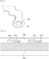
- FIG. 1 is a view illustrating a shape of a first battery terminal connection part formed on a metal plate 10 according to one embodiment of the present invention
- FIG. 2 is a view illustrating shapes of a first battery terminal connection part and a second battery terminal connection part formed on a metal plate according to one embodiment of the present invention.
- the first and second battery terminal connection parts will be respectively described as a first terminal connection part 20 and a second terminal connection part 30.
- a bus bar 1 may include the first terminal connection part 20, the second terminal connection part 30, a fixing part 50, and a terminal main body 60.
- the metal plate 10 may be formed of aluminum and an aluminum alloy or copper and a copper alloy.
- FIG. 1 is a view illustrating a shape of the first terminal connection part 20 primarily formed on the metal plate 10.
- a first press process may be employed to form the first terminal connection part 20.
- An outer shape of the battery terminal connection part including the first terminal connection part 20 may be formed by press processing, and at least one through hole connected to an outer side of a battery may be formed in the first terminal connection part 20.
- a process of making a first through hole 22 passing through the first terminal connection part 20 may also be included in the first press process for manufacturing the outer shape of the first terminal connection part 20.
- a battery electrode may pass through an inner side surface of the first through hole 22 and may be connected to a battery terminal.
- the inner side surface of the first through hole 22 may be plated to minimize variation of contact resistance and reduce resistance of the first through hole 22 serving as an electrical contact part.
- the first terminal connection part 20 may have a circular shape as illustrated in FIG. 1 , but the present invention is not limited thereto and may have an elliptical shape, a polygonal shape, a combined shape formed of curves or straight lines, etc.
- a position of the first terminal connection part 20 is not limited to the example illustrated in FIG. 1 .
- the first press process for the first terminal connection part 20 may include a predetermined area positioned at an outer side thereof.
- a perimeter of the predetermined area may include at least one straight line.
- FIG. 2 is a view illustrating a shape of the second terminal connection part 30 above the first terminal connection part 20 on the metal plate 10.
- the press process may be employed to form an outer shape of the second terminal connection part 30 when performing the first press process.
- An outer shape of a battery terminal connection part including the second terminal connection part 30 may be formed by press processing, and at least one through hole connected to an outer side of a battery may be formed in the second terminal connection part 30.
- a process of making a second through hole 32 may be included in the press process for manufacturing the outer shape of the second terminal connection part 30.
- a battery electrode may pass through an inner side surface of the second through hole 32 and may be connected to a battery terminal.
- the inner side surface of the through hole may be plated to minimize variation of contact resistance and reduce resistance of the second through hole 32 serving as an electrical contact part.
- the second terminal connection part 30 may have a rectangular shape as illustrated in FIG. 2 , but the present invention is not limited thereto and may have an elliptical shape, a polygonal shape, curves or straight lines, a combination of curves and straight lines, etc.
- a position of the second terminal connection part 30 is not limited to an example illustrated in FIG. 2 .
- a predetermined area positioned at an outer side of the second terminal connection part 30 may be included during performing the first press process.
- the perimeter of the predetermined area may include at least one straight line.
- the first terminal connection part 20 and the second terminal connection part 30 which will be connected to a battery terminal may be plated and thermally processed after performing the first press process.
- a masking process may be performed beforehand.
- a mask 40 for plating may be applied onto a remaining area except the first terminal connection part 20, the second terminal connection part 30, and the predetermined areas.
- the mask 40 may also be applied onto the opposite surface of the metal plate 10.
- the masking process, which is performed before performing the plating and the thermal processes, for the plating and the thermal processes may be performed in a method of putting on tape 40a rather than using the mask 40.
- FIG. 6 is a view illustrating a masking process according to another embodiment of the present invention.
- FIG. 6 illustrates a form of putting tape on a remaining area except a battery connection part and a predetermined area.
- a first terminal connection part 20a may be positioned in a direction of one side of a second terminal connection part 30a, and a position of the first terminal connection part 20a may be modified depending on a method of a masking process.
- Tape 40a for plating the first terminal connection part 20a and the second terminal connection part 30a may be put on a remaining area of a metal plate 10a except the first terminal connection part 20a and the second terminal connection part 30a which are formed in one direction.
- the tape 40a may be put on the metal plate 10a in the form of a band because the positions of the first terminal connection part 20a and the second terminal connection part 30a are formed in the same direction.
- the plating may be performed using at least one metal among nickel (Ni), gold (Au), copper (Cu), and tin (Sn).
- the plating may be performed by electroplating, and the mask 40 and the tape 40a applied on the metal plate 10 may be removed after performing the plating.
- FIG. 4 illustrates a shape of the bus bar 1 that is an electrical connector for a battery of an electric vehicle and has shapes of the first terminal connection part 20 and the second terminal connection part 30 in which the plating layers are completed and on which a second press process is performed.
- At least one metal among nickel (Ni), gold (Au), copper (Cu), and tin (Sn) may be used to form the plating layers of the first terminal connection part 20 and the second terminal connection part 30.
- tin plating may be performed after performing nickel plating on the first terminal connection part 20 and the second terminal connection part 30, or the nickel plating may be performed after performing copper plating.
- a cleaning process may be performed to remove the residual plating solution when the plating process is completed.
- a second press process may be used to form an outer shape of the bus bar 1 after performing the plating process, and thereby outer shapes of the terminal main body 60 and the fixing part 50 may be formed.
- a coupling part through hole 52 which may be used to fix a battery of an electric vehicle, may be included in the fixing part 50, and the press process may be performed to make the coupling part through hole 52.
- the first terminal connection part 20 and the second terminal connection part 30 may be connected by the terminal main body 60, and the fixing part 50 and the coupling part through hole 52 may be formed for fixing the bus bar 1 to an outer side of a battery (not shown).
- the terminal main body 60 and the first terminal connection part 20 may be connected using at least one shape of a curve, a straight line, or a combination of a curve and a straight line. As illustrated in FIG. 4 , the terminal main body 60 may have a rectangular shape. However, the present invention is not limited thereto, and the shape of the terminal main body 60 may include a circular or polygonal shape.
- the fixing part 50 for fixing the bus bar 1 to an outer side of a battery may be formed at a lower side of the bus bar 1.
- the terminal main body 60 and the fixing part 50 may be connected using at least one shape of a curve, a straight line, or a combination of a curve and a straight line.
- FIG. 5 is a view in which a through hole plating layer 24 is formed at an inner side surface of the first through hole 22.
- the first through hole 22 may be connected to an outer side of a battery (not shown) via an electrical connection.
- FIG. 7 illustrates a shape of a bus bar 1 according to another embodiment of the present invention.
- FIG. 7A is a view illustrating outer shapes of a first terminal connection part 20b and a second terminal connection part 30b formed by a first press process.
- a press process may be employed to form the outer shapes of the first terminal connection part 20b and the second terminal connection part 30b.
- a mask may be attached to an area except the terminal connection parts for plating and thermally processing the first terminal connection part 20b and the second terminal connection part 30b.
- the plating may be performed using at least one metal among nickel (Ni), gold (Au), copper (Cu), and tin (Sn).
- each of a first terminal 70 and a second terminal 72 may be formed to couple the first terminal connection part 20b and the second terminal connection part 30b.
- a second press process may be performed to form the first terminal 70 and the second terminal 72.
- the first terminal 70 and the second terminal 72 which are respectively connected to the first terminal connection part 20b and the second terminal connection part 30b, may be formed with curves, straight lines, or a combination of straight lines and curves.
- a method of manufacturing the bus bar 1 may be the same as in the embodiment described above.
- a coupling process may be performed to couple the first terminal connection part 20b and the second terminal connection part 30b.
- the first terminal connection part 20b and the second terminal connection part 30b may be coupled by an ultrasonic fusing process.
- the first terminal 70 connected to the first terminal connection part 20b may be mounted on the second terminal 72 connected to second terminal connection part 30b.
- the first terminal 70 may be melted by applying an ultrasonic vibration to the first terminal 70 mounted on the second terminal 72, by which a large amount of heat may be instantaneously generated and the first terminal 70 may thus be fused to the second terminal 72.
- FIG. 7B is a view illustrating a shape in which the first terminal connection part 20b and the second terminal connection part 30b are fused. Positions of the first terminal connection part 20b and the second terminal connection part 30b are not limited to the illustration of FIG.
- Aluminum and an aluminum alloy or copper or a copper alloy may be used as a metal plate of the bus bar 1 manufactured by the ultrasonic fusing process, and the first terminal connection part 20b and the second terminal connection part 30b of dissimilar metals may be fused as well.
- aluminum and an aluminum alloy may be used as the first terminal connection part 20b
- copper and a copper alloy may be used as the second terminal connection part 30b to form the bus bar of dissimilar metals.
- the method of manufacturing the bus bar 1 by the ultrasonic fusing process reduces manufacturing time and maintains continuity of the manufacturing process due to instantaneous fusing of the first terminal 70 and the second terminal 72, thereby enabling mass production. Delays in manufacturing are inevitable in the conventional technologies in which the bus bar 1 is plated after processing the shape of the bus bar 1. In addition, when the shape of the bus bar 1 is processed after the metal plate 10 is plated, the plating layer may not be formed at the inner side surface of the through hole serving as an electrical contact part. Accordingly, a significant amount of manufacturing time is required, and productivity in mass production may be significantly lowered.
- the present invention relates to the bus bar 1 serving as the electrical connector for a battery of an electric vehicle and a method of manufacturing thereof, and the simplified manufacturing process allows minimized manufacturing time and mass production.
- the present invention reduces the problem of a cut off portion of the through hole connected to an outer side of a battery (not shown) not being plated when a metal plate is plated before the press process.
- a method of manufacturing the electrical connector is provided, and the method can reduce processing time of manufacturing the electrical connector by manufacturing the battery terminal connection part at a metal plate in a desired shape and performing a plating process thereon, thereby enabling mass production of the electrical connector.
- a method of manufacturing the electrical connector is provided, and the method can enhance electrical properties in the process of manufacturing the shape of the electrical connector by forming a uniform plating layer also at the inner side surface of the through hole in the battery terminal connection part through which a battery electrode passes.
Landscapes
- Chemical & Material Sciences (AREA)
- Chemical Kinetics & Catalysis (AREA)
- Electrochemistry (AREA)
- General Chemical & Material Sciences (AREA)
- Engineering & Computer Science (AREA)
- Materials Engineering (AREA)
- Metallurgy (AREA)
- Organic Chemistry (AREA)
- Inorganic Chemistry (AREA)
- Manufacturing & Machinery (AREA)
- Connection Of Batteries Or Terminals (AREA)
Claims (15)
- Verfahren zum Herstellen eines elektrischen Verbinders, der mindestens ein Batterieanschlussverbindungsteil (20, 30) mit einem Durchgangsloch (22, 32) darin aufweist, wobei das Verfahren Folgendes umfasst:Durchführen eines ersten Pressvorgangs auf einer Metallplatte (10), um das mindestens eine Batterieanschlussverbindungsteil (20, 30) zu bilden, das ein zu plattierendes Ziel ist;Durchführen eines Maskierens auf einem Bereich, ausgenommen dem Batterieanschlussverbindungsteil (20, 30);Durchführen eines Plattierens auf dem Batterieanschlussverbindungsteil (20, 30); undDurchführen eines zweiten Pressvorgangs, um ein verbleibendes Teil zu bilden, ausgenommen dem mindestens einen Batterieanschlussverbindungsteil (20, 30) in dem elektrischen Verbinder,wobei eine abgeschnittene Fläche des Durchgangslochs (22, 32) auch während des Durchführens des Plattierens auf dem Batterieanschlussverbindungsteil (20, 30) plattiert wird.
- Verfahren nach Anspruch 1, wobei der Pressvorgang durch Entfernen des Teils des Durchgangslochs (22, 32) und eines vorbestimmten Teils, das an einer Außenseite des Batterieanschlussverbindungsteils (20, 30) positioniert ist, durchgeführt wird.
- Verfahren nach Anspruch 1, wobei der elektrische Verbinder eine Sammelschiene (1) aufweist.
- Verfahren nach Anspruch 3, wobei die Sammelschiene (1) in einem Elektrofahrzeug verwendet wird.
- Verfahren nach Anspruch 1, wobei von dem mindestens einen Batterieanschlussverbindungsteil (20, 30) zwei an der Zahl sind.
- Verfahren nach Anspruch 1, wobei eine abgeschnittene Fläche des Durchgangslochs (22, 32) mit einer Außenseite eines Anschlusses der Batterie verbunden wird.
- Verfahren nach Anspruch 2, wobei ein Umfang des vorbestimmten Bereichs mit geraden Linien, Kurven oder einer Kombination aus geraden Linien und Kurven gebildet ist.
- Verfahren nach Anspruch 2, wobei das Maskieren unter Verwendung einer Maske (40) durchgeführt wird, in der das Batterieverbindungsteil (20, 30) und das vorbestimmte Teil entfernt sind.
- Verfahren nach Anspruch 2, wobei das Maskieren durch Auflegen eines Bands (40a) auf einen Bereich, ausgenommen dem Batterieverbindungsteil (20a, 30a) und dem vorbestimmten Teil, durchgeführt wird.
- Verfahren nach Anspruch 1, wobei das Plattieren unter Verwendung mindestens eines Metalls aus Nickel (Ni), Gold (Au), Kupfer (Cu) und Zinn (Sn) durchgeführt wird.
- Verfahren zum Herstellen eines elektrischen Verbinders, der mehrere Batterieanschlussverbindungsteile (20, 30) mit jeweils einem Durchgangsloch (22, 32) darin aufweist, wobei das Verfahren Folgendes umfasst:Durchführen eines ersten Pressvorgangs, um jedes Batterieanschlussverbindungsteil (20, 30) zu bilden, das ein Schmelzziel ist, auf Platten, die sich voneinander unterscheiden, die aus dem gleichen Metallmaterial oder unterschiedlichen Metallmaterialien gebildet sind;Durchführen eines Maskierens auf einem Bereich, ausgenommen dem Batterieanschlussverbindungsteil (20, 30) in jeder Metallmaterialplatte;Durchführen eines Plattierens auf jedem Batterieanschlussverbindungsteil (20, 30);Durchführen eines zweiten Pressvorgangs auf jeder Metallmaterialplatte (10), um ein Kopplungsteil (50) an einem verbleibenden Bereich zu bilden, ausgenommen mindestens einem von dem Batterieanschlussverbindungsteil (20, 30) ; undVerschmelzen der Kopplungsteile (50) miteinander und Vollenden des elektrischen Verbinders,wobei eine abgeschnittene Fläche des Durchgangslochs (22, 32) auch während des Durchführens des Plattierens auf dem Batterieanschlussverbindungsteil (20, 30) plattiert wird.
- Verfahren nach Anspruch 11, wobei das Verschmelzen ein Ultraschallschmelzen oder -schweißen umfasst.
- Verfahren nach Anspruch 11, wobei die Platten (10) aus Metallmaterialien, die voneinander unterschiedlich sind, aus dem gleichen Metallmaterial gebildet sind.
- Verfahren nach Anspruch 11, wobei die Platten (10) aus Metallmaterialien, die voneinander unterschiedlich sind, aus unterschiedlichen Metallmaterialien gebildet sind.
- Verfahren nach Anspruch 11, wobei jede der Metallmaterialplatten (10), die voneinander unterschiedlich sind, unter Verwendung mindestens eines/r aus Aluminium und einer Aluminiumlegierung und Kupfer und einer Kupferlegierung gebildet ist.
Applications Claiming Priority (1)
| Application Number | Priority Date | Filing Date | Title |
|---|---|---|---|
| KR1020150118195A KR101623717B1 (ko) | 2015-08-21 | 2015-08-21 | 전기 연결 수단의 제조 방법 |
Publications (2)
| Publication Number | Publication Date |
|---|---|
| EP3133676A1 EP3133676A1 (de) | 2017-02-22 |
| EP3133676B1 true EP3133676B1 (de) | 2019-08-21 |
Family
ID=56114099
Family Applications (1)
| Application Number | Title | Priority Date | Filing Date |
|---|---|---|---|
| EP16185155.5A Active EP3133676B1 (de) | 2015-08-21 | 2016-08-22 | Verfahren zur herstellung eines elektrischen verbinders |
Country Status (5)
| Country | Link |
|---|---|
| US (1) | US10573874B2 (de) |
| EP (1) | EP3133676B1 (de) |
| KR (1) | KR101623717B1 (de) |
| CN (1) | CN106469800A (de) |
| HU (1) | HUE046208T2 (de) |
Families Citing this family (6)
| Publication number | Priority date | Publication date | Assignee | Title |
|---|---|---|---|---|
| KR102383415B1 (ko) | 2018-03-20 | 2022-04-06 | 삼성에스디아이 주식회사 | 배터리 팩 |
| KR101996444B1 (ko) * | 2018-04-25 | 2019-10-01 | 주식회사 유라코퍼레이션 | 버스바 어셈블리 |
| KR102239209B1 (ko) * | 2018-10-24 | 2021-04-12 | 대산전자(주) | 도금방법 및 도금체 |
| KR102041494B1 (ko) * | 2019-01-22 | 2019-11-07 | 에스 티 (주) | 전기차용 배터리 연결 버스바의 제조방법 |
| CN110311083A (zh) * | 2019-07-24 | 2019-10-08 | 宁波市叶兴汽车零部件有限公司 | 车用电池连接件加工工艺 |
| KR102819127B1 (ko) * | 2020-03-31 | 2025-06-12 | 주식회사 엘지에너지솔루션 | 이종금속으로 이루어진 hv 버스 바 및 이의 제조 방법 |
Family Cites Families (14)
| Publication number | Priority date | Publication date | Assignee | Title |
|---|---|---|---|---|
| JPS59126784A (ja) | 1982-12-28 | 1984-07-21 | Fujitsu Ltd | コネクタ端子の製造方法 |
| KR100737973B1 (ko) | 2005-11-25 | 2007-07-13 | 주식회사 우주금속 | 휴대폰 배터리 단자용 금속소재의 표면처리방법 |
| US9196890B2 (en) * | 2009-10-05 | 2015-11-24 | Samsung Sdi Co., Ltd. | Battery module with welded portion between terminals |
| KR20120138790A (ko) | 2010-03-29 | 2012-12-26 | 가부시키가이샤 고베 세이코쇼 | 버스 바 및 버스 바의 제조 방법 |
| JP5715766B2 (ja) * | 2010-04-22 | 2015-05-13 | 矢崎総業株式会社 | 配線材の接続構造 |
| CN103250303B (zh) * | 2010-12-08 | 2015-11-25 | 古河电气工业株式会社 | 压接端子、连接构造体以及它们的制造方法 |
| JP5657418B2 (ja) * | 2011-02-16 | 2015-01-21 | 株式会社Uacj | 車載用バスバー及びその製造方法 |
| JP5965396B2 (ja) * | 2011-06-02 | 2016-08-03 | 株式会社日立金属ネオマテリアル | 電池用負極端子および電池用負極端子の製造方法 |
| US9318734B2 (en) | 2012-05-21 | 2016-04-19 | Tyco Electronics Corporation | Bimetal buss bar assembly |
| JP2015187910A (ja) * | 2012-08-09 | 2015-10-29 | 三洋電機株式会社 | 電池パック及びこれを備える電動車両並びに蓄電装置 |
| JP2015187909A (ja) * | 2012-08-09 | 2015-10-29 | 三洋電機株式会社 | 電池パック及びこれを備える電動車両並びに蓄電装置 |
| JP6257889B2 (ja) * | 2012-10-23 | 2018-01-10 | 日本メクトロン株式会社 | バスバー付きフレキシブルプリント配線板およびその製造方法、並びにバッテリシステム |
| US20140134471A1 (en) * | 2012-11-14 | 2014-05-15 | General Electric Company | Electrical interconnect and method of assembling a rechargeable battery |
| JP2014143159A (ja) | 2012-12-28 | 2014-08-07 | Hitachi Metals Ltd | 電極端子接続体の製造方法 |
-
2015
- 2015-08-21 KR KR1020150118195A patent/KR101623717B1/ko active Active
-
2016
- 2016-08-19 CN CN201610694502.8A patent/CN106469800A/zh active Pending
- 2016-08-22 EP EP16185155.5A patent/EP3133676B1/de active Active
- 2016-08-22 US US15/242,710 patent/US10573874B2/en active Active
- 2016-08-22 HU HUE16185155A patent/HUE046208T2/hu unknown
Non-Patent Citations (1)
| Title |
|---|
| None * |
Also Published As
| Publication number | Publication date |
|---|---|
| KR101623717B1 (ko) | 2016-05-24 |
| CN106469800A (zh) | 2017-03-01 |
| HUE046208T2 (hu) | 2020-02-28 |
| EP3133676A1 (de) | 2017-02-22 |
| US10573874B2 (en) | 2020-02-25 |
| US20170054132A1 (en) | 2017-02-23 |
Similar Documents
| Publication | Publication Date | Title |
|---|---|---|
| EP3133676B1 (de) | Verfahren zur herstellung eines elektrischen verbinders | |
| CN108140958B (zh) | 导电构件、带有端子的导电构件及导电构件制造方法 | |
| CN104241151B (zh) | 用于制造半导体模块的方法 | |
| US20150111442A1 (en) | Terminal-provided wire, method for manufacturing same and jig | |
| TWI383553B (zh) | 同軸電纜線束之連接構造及連接方法 | |
| CN108352215B (zh) | 导电部件以及导电部件的制造方法 | |
| EP3029773B1 (de) | Litzendrahtanschlussanordnung | |
| JP6252694B2 (ja) | 配線部材およびその製造方法 | |
| JP2013131434A (ja) | 可撓導体および可撓導体の製造方法 | |
| WO2015111509A1 (ja) | 端子金具付き電線及びその製造方法 | |
| CN108630342A (zh) | 一种软母线及其制备方法 | |
| JPWO2014077144A1 (ja) | 端子金具付き電線 | |
| US2799840A (en) | Terminal construction | |
| JP6062593B1 (ja) | 平編組線導体の製造方法 | |
| CN103578740B (zh) | 芯片线圈的制造方法 | |
| EP3841841B1 (de) | Stoffkontakteinrichtung, system, insbesondere heizsystem für ein kraftfahrzeug, und verfahren zur herstellung eines solchen systems | |
| JP2004511888A (ja) | フラットラミネートケーブルを接続する方法 | |
| WO2013183160A1 (ja) | 端子金具付き電線及び端子金具付き電線の製造方法 | |
| WO2014077143A1 (ja) | 端子金具付き電線 | |
| JPH1126913A (ja) | 配線基板の製造方法 | |
| CN108352668A (zh) | 带端子的导电构件的制造方法以及导电构件 | |
| KR102732872B1 (ko) | 수직 와이어 구조를 이용한 접합 소재 및 그 제조방법 | |
| US20260005181A1 (en) | Semiconductor device and a method of manufacturing of the semiconductor device | |
| CN104953219A (zh) | Rf板端连接器及其制造方法 | |
| JP2012222316A (ja) | 熱圧着用ヒーターチップ、及び、熱圧着方法 |
Legal Events
| Date | Code | Title | Description |
|---|---|---|---|
| PUAI | Public reference made under article 153(3) epc to a published international application that has entered the european phase |
Free format text: ORIGINAL CODE: 0009012 |
|
| STAA | Information on the status of an ep patent application or granted ep patent |
Free format text: STATUS: THE APPLICATION HAS BEEN PUBLISHED |
|
| AK | Designated contracting states |
Kind code of ref document: A1 Designated state(s): AL AT BE BG CH CY CZ DE DK EE ES FI FR GB GR HR HU IE IS IT LI LT LU LV MC MK MT NL NO PL PT RO RS SE SI SK SM TR |
|
| AX | Request for extension of the european patent |
Extension state: BA ME |
|
| STAA | Information on the status of an ep patent application or granted ep patent |
Free format text: STATUS: REQUEST FOR EXAMINATION WAS MADE |
|
| 17P | Request for examination filed |
Effective date: 20170822 |
|
| RBV | Designated contracting states (corrected) |
Designated state(s): AL AT BE BG CH CY CZ DE DK EE ES FI FR GB GR HR HU IE IS IT LI LT LU LV MC MK MT NL NO PL PT RO RS SE SI SK SM TR |
|
| GRAP | Despatch of communication of intention to grant a patent |
Free format text: ORIGINAL CODE: EPIDOSNIGR1 |
|
| STAA | Information on the status of an ep patent application or granted ep patent |
Free format text: STATUS: GRANT OF PATENT IS INTENDED |
|
| RIC1 | Information provided on ipc code assigned before grant |
Ipc: H01M 2/20 20060101ALI20190128BHEP Ipc: C25D 5/02 20060101ALI20190128BHEP Ipc: C25D 7/00 20060101ALI20190128BHEP Ipc: H01M 2/30 20060101AFI20190128BHEP |
|
| INTG | Intention to grant announced |
Effective date: 20190305 |
|
| GRAS | Grant fee paid |
Free format text: ORIGINAL CODE: EPIDOSNIGR3 |
|
| GRAA | (expected) grant |
Free format text: ORIGINAL CODE: 0009210 |
|
| STAA | Information on the status of an ep patent application or granted ep patent |
Free format text: STATUS: THE PATENT HAS BEEN GRANTED |
|
| AK | Designated contracting states |
Kind code of ref document: B1 Designated state(s): AL AT BE BG CH CY CZ DE DK EE ES FI FR GB GR HR HU IE IS IT LI LT LU LV MC MK MT NL NO PL PT RO RS SE SI SK SM TR |
|
| REG | Reference to a national code |
Ref country code: GB Ref legal event code: FG4D |
|
| REG | Reference to a national code |
Ref country code: CH Ref legal event code: EP |
|
| REG | Reference to a national code |
Ref country code: DE Ref legal event code: R096 Ref document number: 602016018876 Country of ref document: DE |
|
| REG | Reference to a national code |
Ref country code: AT Ref legal event code: REF Ref document number: 1170765 Country of ref document: AT Kind code of ref document: T Effective date: 20190915 |
|
| REG | Reference to a national code |
Ref country code: IE Ref legal event code: FG4D |
|
| REG | Reference to a national code |
Ref country code: LT Ref legal event code: MG4D |
|
| REG | Reference to a national code |
Ref country code: NL Ref legal event code: MP Effective date: 20190821 |
|
| PG25 | Lapsed in a contracting state [announced via postgrant information from national office to epo] |
Ref country code: HR Free format text: LAPSE BECAUSE OF FAILURE TO SUBMIT A TRANSLATION OF THE DESCRIPTION OR TO PAY THE FEE WITHIN THE PRESCRIBED TIME-LIMIT Effective date: 20190821 Ref country code: LT Free format text: LAPSE BECAUSE OF FAILURE TO SUBMIT A TRANSLATION OF THE DESCRIPTION OR TO PAY THE FEE WITHIN THE PRESCRIBED TIME-LIMIT Effective date: 20190821 Ref country code: NO Free format text: LAPSE BECAUSE OF FAILURE TO SUBMIT A TRANSLATION OF THE DESCRIPTION OR TO PAY THE FEE WITHIN THE PRESCRIBED TIME-LIMIT Effective date: 20191121 Ref country code: FI Free format text: LAPSE BECAUSE OF FAILURE TO SUBMIT A TRANSLATION OF THE DESCRIPTION OR TO PAY THE FEE WITHIN THE PRESCRIBED TIME-LIMIT Effective date: 20190821 Ref country code: SE Free format text: LAPSE BECAUSE OF FAILURE TO SUBMIT A TRANSLATION OF THE DESCRIPTION OR TO PAY THE FEE WITHIN THE PRESCRIBED TIME-LIMIT Effective date: 20190821 Ref country code: PT Free format text: LAPSE BECAUSE OF FAILURE TO SUBMIT A TRANSLATION OF THE DESCRIPTION OR TO PAY THE FEE WITHIN THE PRESCRIBED TIME-LIMIT Effective date: 20191223 Ref country code: NL Free format text: LAPSE BECAUSE OF FAILURE TO SUBMIT A TRANSLATION OF THE DESCRIPTION OR TO PAY THE FEE WITHIN THE PRESCRIBED TIME-LIMIT Effective date: 20190821 Ref country code: BG Free format text: LAPSE BECAUSE OF FAILURE TO SUBMIT A TRANSLATION OF THE DESCRIPTION OR TO PAY THE FEE WITHIN THE PRESCRIBED TIME-LIMIT Effective date: 20191121 |
|
| PG25 | Lapsed in a contracting state [announced via postgrant information from national office to epo] |
Ref country code: RS Free format text: LAPSE BECAUSE OF FAILURE TO SUBMIT A TRANSLATION OF THE DESCRIPTION OR TO PAY THE FEE WITHIN THE PRESCRIBED TIME-LIMIT Effective date: 20190821 Ref country code: LV Free format text: LAPSE BECAUSE OF FAILURE TO SUBMIT A TRANSLATION OF THE DESCRIPTION OR TO PAY THE FEE WITHIN THE PRESCRIBED TIME-LIMIT Effective date: 20190821 Ref country code: GR Free format text: LAPSE BECAUSE OF FAILURE TO SUBMIT A TRANSLATION OF THE DESCRIPTION OR TO PAY THE FEE WITHIN THE PRESCRIBED TIME-LIMIT Effective date: 20191122 Ref country code: ES Free format text: LAPSE BECAUSE OF FAILURE TO SUBMIT A TRANSLATION OF THE DESCRIPTION OR TO PAY THE FEE WITHIN THE PRESCRIBED TIME-LIMIT Effective date: 20190821 Ref country code: AL Free format text: LAPSE BECAUSE OF FAILURE TO SUBMIT A TRANSLATION OF THE DESCRIPTION OR TO PAY THE FEE WITHIN THE PRESCRIBED TIME-LIMIT Effective date: 20190821 Ref country code: IS Free format text: LAPSE BECAUSE OF FAILURE TO SUBMIT A TRANSLATION OF THE DESCRIPTION OR TO PAY THE FEE WITHIN THE PRESCRIBED TIME-LIMIT Effective date: 20191221 |
|
| REG | Reference to a national code |
Ref country code: HU Ref legal event code: AG4A Ref document number: E046208 Country of ref document: HU |
|
| PG25 | Lapsed in a contracting state [announced via postgrant information from national office to epo] |
Ref country code: TR Free format text: LAPSE BECAUSE OF FAILURE TO SUBMIT A TRANSLATION OF THE DESCRIPTION OR TO PAY THE FEE WITHIN THE PRESCRIBED TIME-LIMIT Effective date: 20190821 |
|
| PG25 | Lapsed in a contracting state [announced via postgrant information from national office to epo] |
Ref country code: PL Free format text: LAPSE BECAUSE OF FAILURE TO SUBMIT A TRANSLATION OF THE DESCRIPTION OR TO PAY THE FEE WITHIN THE PRESCRIBED TIME-LIMIT Effective date: 20190821 Ref country code: RO Free format text: LAPSE BECAUSE OF FAILURE TO SUBMIT A TRANSLATION OF THE DESCRIPTION OR TO PAY THE FEE WITHIN THE PRESCRIBED TIME-LIMIT Effective date: 20190821 Ref country code: IT Free format text: LAPSE BECAUSE OF FAILURE TO SUBMIT A TRANSLATION OF THE DESCRIPTION OR TO PAY THE FEE WITHIN THE PRESCRIBED TIME-LIMIT Effective date: 20190821 Ref country code: EE Free format text: LAPSE BECAUSE OF FAILURE TO SUBMIT A TRANSLATION OF THE DESCRIPTION OR TO PAY THE FEE WITHIN THE PRESCRIBED TIME-LIMIT Effective date: 20190821 Ref country code: DK Free format text: LAPSE BECAUSE OF FAILURE TO SUBMIT A TRANSLATION OF THE DESCRIPTION OR TO PAY THE FEE WITHIN THE PRESCRIBED TIME-LIMIT Effective date: 20190821 |
|
| PG25 | Lapsed in a contracting state [announced via postgrant information from national office to epo] |
Ref country code: CH Free format text: LAPSE BECAUSE OF NON-PAYMENT OF DUE FEES Effective date: 20190831 Ref country code: LU Free format text: LAPSE BECAUSE OF NON-PAYMENT OF DUE FEES Effective date: 20190822 Ref country code: SM Free format text: LAPSE BECAUSE OF FAILURE TO SUBMIT A TRANSLATION OF THE DESCRIPTION OR TO PAY THE FEE WITHIN THE PRESCRIBED TIME-LIMIT Effective date: 20190821 Ref country code: CZ Free format text: LAPSE BECAUSE OF FAILURE TO SUBMIT A TRANSLATION OF THE DESCRIPTION OR TO PAY THE FEE WITHIN THE PRESCRIBED TIME-LIMIT Effective date: 20190821 Ref country code: MC Free format text: LAPSE BECAUSE OF FAILURE TO SUBMIT A TRANSLATION OF THE DESCRIPTION OR TO PAY THE FEE WITHIN THE PRESCRIBED TIME-LIMIT Effective date: 20190821 Ref country code: IS Free format text: LAPSE BECAUSE OF FAILURE TO SUBMIT A TRANSLATION OF THE DESCRIPTION OR TO PAY THE FEE WITHIN THE PRESCRIBED TIME-LIMIT Effective date: 20200224 Ref country code: LI Free format text: LAPSE BECAUSE OF NON-PAYMENT OF DUE FEES Effective date: 20190831 Ref country code: SK Free format text: LAPSE BECAUSE OF FAILURE TO SUBMIT A TRANSLATION OF THE DESCRIPTION OR TO PAY THE FEE WITHIN THE PRESCRIBED TIME-LIMIT Effective date: 20190821 |
|
| REG | Reference to a national code |
Ref country code: BE Ref legal event code: MM Effective date: 20190831 |
|
| REG | Reference to a national code |
Ref country code: DE Ref legal event code: R097 Ref document number: 602016018876 Country of ref document: DE |
|
| PLBE | No opposition filed within time limit |
Free format text: ORIGINAL CODE: 0009261 |
|
| STAA | Information on the status of an ep patent application or granted ep patent |
Free format text: STATUS: NO OPPOSITION FILED WITHIN TIME LIMIT |
|
| PG2D | Information on lapse in contracting state deleted |
Ref country code: IS |
|
| PG25 | Lapsed in a contracting state [announced via postgrant information from national office to epo] |
Ref country code: IE Free format text: LAPSE BECAUSE OF NON-PAYMENT OF DUE FEES Effective date: 20190822 |
|
| 26N | No opposition filed |
Effective date: 20200603 |
|
| PG25 | Lapsed in a contracting state [announced via postgrant information from national office to epo] |
Ref country code: BE Free format text: LAPSE BECAUSE OF NON-PAYMENT OF DUE FEES Effective date: 20190831 Ref country code: SI Free format text: LAPSE BECAUSE OF FAILURE TO SUBMIT A TRANSLATION OF THE DESCRIPTION OR TO PAY THE FEE WITHIN THE PRESCRIBED TIME-LIMIT Effective date: 20190821 |
|
| REG | Reference to a national code |
Ref country code: DE Ref legal event code: R079 Ref document number: 602016018876 Country of ref document: DE Free format text: PREVIOUS MAIN CLASS: H01M0002300000 Ipc: H01M0050543000 |
|
| PG25 | Lapsed in a contracting state [announced via postgrant information from national office to epo] |
Ref country code: CY Free format text: LAPSE BECAUSE OF FAILURE TO SUBMIT A TRANSLATION OF THE DESCRIPTION OR TO PAY THE FEE WITHIN THE PRESCRIBED TIME-LIMIT Effective date: 20190821 |
|
| PG25 | Lapsed in a contracting state [announced via postgrant information from national office to epo] |
Ref country code: MT Free format text: LAPSE BECAUSE OF FAILURE TO SUBMIT A TRANSLATION OF THE DESCRIPTION OR TO PAY THE FEE WITHIN THE PRESCRIBED TIME-LIMIT Effective date: 20190821 |
|
| PG25 | Lapsed in a contracting state [announced via postgrant information from national office to epo] |
Ref country code: MK Free format text: LAPSE BECAUSE OF FAILURE TO SUBMIT A TRANSLATION OF THE DESCRIPTION OR TO PAY THE FEE WITHIN THE PRESCRIBED TIME-LIMIT Effective date: 20190821 |
|
| REG | Reference to a national code |
Ref country code: AT Ref legal event code: UEP Ref document number: 1170765 Country of ref document: AT Kind code of ref document: T Effective date: 20190821 |
|
| PGFP | Annual fee paid to national office [announced via postgrant information from national office to epo] |
Ref country code: HU Payment date: 20250814 Year of fee payment: 10 |
|
| PGFP | Annual fee paid to national office [announced via postgrant information from national office to epo] |
Ref country code: DE Payment date: 20250819 Year of fee payment: 10 |
|
| PGFP | Annual fee paid to national office [announced via postgrant information from national office to epo] |
Ref country code: GB Payment date: 20250822 Year of fee payment: 10 |
|
| PGFP | Annual fee paid to national office [announced via postgrant information from national office to epo] |
Ref country code: AT Payment date: 20250819 Year of fee payment: 10 Ref country code: FR Payment date: 20250821 Year of fee payment: 10 |