EP3136187B1 - Montre mecanique dotee d'un tourbillon - Google Patents
Montre mecanique dotee d'un tourbillon Download PDFInfo
- Publication number
- EP3136187B1 EP3136187B1 EP15183133.6A EP15183133A EP3136187B1 EP 3136187 B1 EP3136187 B1 EP 3136187B1 EP 15183133 A EP15183133 A EP 15183133A EP 3136187 B1 EP3136187 B1 EP 3136187B1
- Authority
- EP
- European Patent Office
- Prior art keywords
- balance
- zero
- cage
- clockwork movement
- movement according
- Prior art date
- Legal status (The legal status is an assumption and is not a legal conclusion. Google has not performed a legal analysis and makes no representation as to the accuracy of the status listed.)
- Active
Links
Images


Classifications
-
- G—PHYSICS
- G04—HOROLOGY
- G04B—MECHANICALLY-DRIVEN CLOCKS OR WATCHES; MECHANICAL PARTS OF CLOCKS OR WATCHES IN GENERAL; TIME PIECES USING THE POSITION OF THE SUN, MOON OR STARS
- G04B17/00—Mechanisms for stabilising frequency
- G04B17/20—Compensation of mechanisms for stabilising frequency
- G04B17/28—Compensation of mechanisms for stabilising frequency for the effect of imbalance of the weights, e.g. tourbillon
- G04B17/285—Tourbillons or carrousels
-
- G—PHYSICS
- G04—HOROLOGY
- G04B—MECHANICALLY-DRIVEN CLOCKS OR WATCHES; MECHANICAL PARTS OF CLOCKS OR WATCHES IN GENERAL; TIME PIECES USING THE POSITION OF THE SUN, MOON OR STARS
- G04B17/00—Mechanisms for stabilising frequency
- G04B17/04—Oscillators acting by spring tension
- G04B17/06—Oscillators with hairsprings, e.g. balance
- G04B17/063—Balance construction
-
- G—PHYSICS
- G04—HOROLOGY
- G04B—MECHANICALLY-DRIVEN CLOCKS OR WATCHES; MECHANICAL PARTS OF CLOCKS OR WATCHES IN GENERAL; TIME PIECES USING THE POSITION OF THE SUN, MOON OR STARS
- G04B27/00—Mechanical devices for setting the time indicating means
- G04B27/004—Mechanical devices for setting the time indicating means having several simultaneous functions, e.g. stopping or starting the clockwork or the hands
-
- G—PHYSICS
- G04—HOROLOGY
- G04B—MECHANICALLY-DRIVEN CLOCKS OR WATCHES; MECHANICAL PARTS OF CLOCKS OR WATCHES IN GENERAL; TIME PIECES USING THE POSITION OF THE SUN, MOON OR STARS
- G04B27/00—Mechanical devices for setting the time indicating means
- G04B27/005—Mechanical devices for setting the time indicating means stepwise or on determined values
-
- G—PHYSICS
- G04—HOROLOGY
- G04B—MECHANICALLY-DRIVEN CLOCKS OR WATCHES; MECHANICAL PARTS OF CLOCKS OR WATCHES IN GENERAL; TIME PIECES USING THE POSITION OF THE SUN, MOON OR STARS
- G04B27/00—Mechanical devices for setting the time indicating means
- G04B27/02—Mechanical devices for setting the time indicating means by making use of the winding means
- G04B27/026—Mechanical devices for setting the time indicating means by making use of the winding means for several clockworks or pairs of hands and/or supplementary functions
Definitions
- the present invention relates to a mechanical movement with a tourbillon and a mechanical clock equipped therewith.
- Tourbillons for mechanical watches and movements are well known.
- the escape wheel, the anchor and the so-called balance of the movement are arranged on a bogie, which is coupled to the shaft of the second wheel, and thus the second drive, or firmly connected.
- the balance or balance axis typically coincides with an imaginary axle extension of the second drive.
- a gearwheel connected to the escape wheel meshes with a stationary gear wheel arranged coaxially with the balance axis, so that the tourbillon, and therefore its frame, undergoes a complete revolution per minute.
- balance rest which can be activated for example by pulling out a crown and deactivated by pushing the crown wheel back.
- a rest stop for a tourbillon is from the EP 2 793 087 A1 known. This has a with the balance engageable and axially to the balance axis movable brake element. To balance the clock with a time standard, it is thus possible to stop the balance and thus the tourbillon mechanism as desired.
- the present invention is an object of the invention to provide an improved rest stop for a tourbillon of a mechanical watch.
- a zero position of the tourbillon for comfortable timing can be realized. This is to improve the operability and the time setting of the clock and also give the clock an increased range of functions.
- a clockwork of a mechanical watch with a tourbillon unit is provided.
- the movement has a board on which all movable components of the movement are arranged.
- the movement, in particular its tourbillon unit further has a frame connected to a second drive, rotatably mounted on the board frame and mounted on the frame balance.
- a second drive In addition to the balance, an escape wheel in operative connection with the balance is also mounted on the frame.
- the escape wheel is typically via an armature in operative connection with the balance.
- the balance, the anchor and the escape wheel form the inhibition of the mechanical movement.
- the second drive is typically coupled to an energy storage device, such as a barrel, which ultimately drives the movement.
- the movement is further provided with a balance engageable with the balance rest device.
- the balance stop device By means of the balance stop device, the balance for stopping the movement relative to the board or relative to the frame at least temporarily fixed.
- the movement is provided with a zeroing device, which allows to adjust the angular orientation of the frame in a predetermined position, which preferably corresponds to the zero position of a mounted on the frame second hand.
- the zeroing device is optionally rotatably engageable with the frame or with the board.
- the zeroing device is typically in the normal operation of the clock with the circuit board rotatably engaged.
- the zeroing device is fixed relative to or on the board, while the frame together with the entire tourbillon unit is subjected to a rotational movement relative to the board.
- the zeroing device is also detachable from the circuit board or rotatably decoupled, so that it can be rotated relative to the board. In this case, it is typically rotatably engaged with the frame.
- the zeroing device is thus always either with the frame rotatably engaged or rotatably engaged with the board or the zeroing device is even with both the frame and the circuit board rotatably engaged.
- rotatably engageable zeroing device By selectively with the frame or with the board rotatably engageable zeroing device can be achieved to decouple the frame for adjusting the time at least temporarily from the energy storage device of the movement.
- an alternate fixation or rotationally fixed connection of the zeroing device with the frame or with the board can be achieved that the zeroing device together with the frame to bring about a zero stop function also approximately under the action of the mechanical Energy storage of the movement, but decoupled from the minute or hourly drive of the movement in a defined zero position can be converted.
- the optional engagement of the zeroing device with the frame or with the board can be done by successive and stepwise pulling out a crown, such as an elevator or Einstellkrone the clockwork.
- a crown such as an elevator or Einstellkrone the clockwork.
- the crown may be in three different axial positions, ie a first so-called rest position in which, for example, a barrel can be wound through the crown as usual, a second position in which the balance is stopped, eg according to the solution of EP2793087 , and a third further drawn axial position in which the zeroing device is no longer engaged with the board, but now with the frame in engagement.
- the minute hand position can be provided by turning the crown in this position.
- the zeroing device in a basic configuration, is fixed against rotation on the circuit board.
- the crown In the basic configuration, the crown is in a basic position, in which the movement is driven by the mechanical energy storage in motion. Due to the fixation on the board, the zeroing device acts as a kind of basis for the tourbillon unit. It may be provided in particular that the tourbillon unit or part thereof with the Zero setting are in operative connection. In the basic configuration with a zero-setting device fixed on the board, this only acts as a carrier for other mechanical components of the movement, for example for the tourbillon unit or for individual components thereof.
- the zeroing device is non-rotatably coupled to the frame when the balance is stopped by means of the balance rest stop device.
- the frame is freely rotatably mounted relative to the board. That is, only under the influence of the inhibition, the frame rotates relative to the board under the action of the spring drive outgoing mechanical drive energy.
- the zeroing device and the balance stop device interact with one another in such a way that the zeroing device is rotationally fixedly coupled to the frame by activating the balance stop device. It is also conceivable that the zeroing device is already firmly connected to the balance stop device. A fixation of the frame relative to the board by means of the balance rest device thus inevitably leads to a rotationally fixed fixing of the frame relative to the zeroing device.
- the zeroing device By a direct or indirect coupling of zeroing device and frame can be achieved that about the purpose of setting the clock, the zeroing device is rotatably connected to the frame. By means of the zeroing device can then be transferred from any position in which the frame was stopped, the frame fixed thereto in a defined zero position in which a second hand arranged on the frame pointer points to zero.
- the balance stop device has a bogie and frictionally engaged with the balance in Engage engageable axially to a balance axis movable brake element.
- a balance rest can be realized, which exerts no radial asymmetric forces on the balance or on the bogie of the tourbillon.
- the balance can also be braked directly via the brake element, in particular stopped. By slowing down and stopping the balance will inevitably stop the rotation of the tourbillon, that is, the rotational movement of the bogie.
- the balance-rest device acts exclusively on the balance in the axial direction makes the balance-rest stop device particularly suitable for achieving a rest stop in the case of a flying tourbillon.
- a frictional braking of the balance also allows the balance to be stopped in any arbitrary orientation and position of the balance.
- the zeroing device via the brake element rotatably coupled to the frame.
- the zeroing device can, in particular, act directly or indirectly on the brake element arranged, for example, on the frame.
- the zeroing device but at least individual components or parts thereof may or may be in particular in the power flow of the balance rest stop device.
- the zeroing device by means of a fixing member rotationally fixed to the board can be fixed.
- the zeroing device can optionally be fixed in a rotationally fixed manner to the printed circuit board or else detached therefrom, so that the zeroing device is rotatable with respect to the printed circuit board.
- the fixing element can be transferred only in a rotationally fixed coupling of frame and zeroing device in a release position, in which the zeroing device is rotatable together with the frame relative to the board.
- the frame is coupled to the zeroing device and the fixing element is transferred to the release position, typically an optionally damped rotational movement of the ensemble formed by frame and zeroing ensembles, wherein the bogie is operatively connected by the activated balance device with the energy storage device of the movement.
- the second drive of the tourbillon is in this configuration still with the energy storage device of the movement, such as the barrel, in mechanical operative connection.
- a pawl is further arranged to be movable on the board. This cooperates with a frame arranged on the locking cam to stop the frame in a neutral position.
- the pawl for example, can be transferred radially inwardly into a locking position, in which they are so with the locking cam of the Gestells cooperates, which prevents rotation of the frame beyond the pawl or past the pawl.
- the latching cam may, for example, protrude radially outward from the frame.
- the pawl is, for example, in a radially inwardly engaged detent position and the zeroing device together with the frame subject of a rotary motion at a located in the release position fixing element, the locking cam of the frame comes into engagement with the pawl.
- the pawl thus acts as an end stop for the locking cam and thus for the frame so that it comes to rest in the intended zero position for adjusting the movement.
- the pawl is coupled to the fixing element.
- the pawl is at least only in a detent position for stopping the frame when the fixing passes from the fixing position in the release position.
- the pawl and the fixing are so far rigidly coupled together. If the ensemble of frame and zeroing device is released for rotational movement, the pawl engages radially inward to stop the free rotation of the ensemble at a fixed predetermined position.
- detent cam and pawl thus determines the zero position of the frame and thus the arranged on the frame second hand of the tourbillon.
- the zeroing device has a carrier wheel with a rim-like circulation tire.
- the circulating tire is rotatably mounted on its outer circumference at least three arranged on the board bearing rollers.
- the zeroing device has in particular a ring-like basic geometry.
- the hub of the tourbillon unit typically extends through the remaining center of the nulling device.
- the zeroing device on a ring-like epicyclic gear with an internal toothing, which meshes with a pinion of the escape wheel.
- the planetary gear of the zeroing device which is also fixed relative to the board in the basic configuration or while the movement is running, meshes with the escape wheel.
- the escapement wheel moves in particular due to the teeth of its pinion with the internal toothing along that internal toothing, when the tourbillon unit is subject to a prevailing during operation of the movement rotational movement.
- the zeroing device acts in this respect as an extended board, on the internal toothing of which the escape wheel runs along with its pinion.
- the zeroing device has a, relative to its axis of rotation, axially movable stop ring. This has on a radially outer edge on a run-on slope, which corresponds to a run-on slope of a movable arranged on the board stop pawl. Typically, two diametrically opposed stop pawls are provided. These can experience a radially inwardly directed movement in the direction of the stop ring with a pulling out of the crown.
- stop ring undergoes an axial movement when the stop pawl or the pawls are moved radially inward.
- a radial movement can thus be converted into an axial movement.
- the at least one pawl of the zeroing device can be deflected radially inwards by an axial movement of the stop ring induced by means of the at least one stop pawl.
- the at least one pawl at its radially inner end on a run-on slope, which is engageable with a run-on slope of a brake ring.
- the brake ring is typically disposed axially adjacent the pawl and is also axially slidable relative to the zeroing device on a major axis of the tourbillon unit, for example, on the hub of the tourbillon unit. Since the at least one pawl and the brake ring engaging therewith have mutually corresponding run-on slopes, the typically radially inwardly directed pivoting or adjusting movement of the pawl can be transmitted into an axially directed displacement movement of the brake ring.
- a brake pin is axially movably guided in a hub of the tourbillon unit or in the frame and for the deflection of the brake element and for stopping the balance by means of the brake ring axially is displaceable.
- the brake pin is in particular against a restoring force, in particular against the action of a spring element axially displaceable to the brake ring.
- the brake pin deflects the brake element, which is movable axially relative to the balance spring, in such a way that it frictionally engages with the balance and finally stops the balance.
- At the zeroing device is typically not only one, but there are several, approximately three circumferentially equidistantly arranged pawls provided, which perform a synchronous, radially inwardly directed movement due to an axial movement of the adjacent thereto arranged stop ring. Accordingly, a possible uniform and symmetrical displacement force can be exerted on the brake ring, which ultimately leads to the axial propulsion of the brake pin.
- a watch in particular a mechanical wristwatch is provided, which is equipped with a previously described movement.
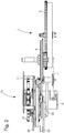
- a tourbillon unit 10 of a mechanical movement 1 not shown in its entirety is illustrated.
- the movement 1 has a board 2, on which the tourbillon unit 10 is rotatably mounted.
- the tourbillon unit 10 is, as from a synopsis of Fig. 2 and 11 emerges coupled via a second drive 5 with a Kleinêtrad 7.
- the Kleinêtrad 7 meshes with a minute wheel 8, which is in engagement with a barrel 9, which in the present case acts as a mechanical energy storage device.
- the tourbillon unit 10 also has an in Fig. 11 shown in cross-section hub 6, which is rotatably mounted on the board 2 and fixedly connected to a frame 11 of the tourbillon unit 10.
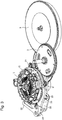
- the frame 11 comprises a lower frame 11a with various radially aligned spokes 11d, via which the frame 11 is connected to the hub 6. About the outer circumference of the lower frame 11 a three vertically or axially aligned pillar 11 c are arranged in the present case. At the lower frame 11a facing away from the end portion, an upper frame 11b is arranged. Between the upper and the lower frame 11a, 11a, the balance 15 of the movement 1 is mounted. The balance 15 is pivotally mounted with respect to a balance shaft 17, wherein the balance shaft 17 is in extension of the second drive 5.
- the balance 15 is further coupled to a balance spring 16.
- an escapement 14 is also provided on the frame 11 so far an escape wheel 12 is rotatably mounted.
- the axis of rotation of the escape wheel 12 in this case extends parallel to the balance axis 17.
- the escapement 14 also has an anchor, which is not explicitly shown here, which alternately engages with the teeth of the escape wheel 14 in a known manner.
- the balance 16, the anchor not explicitly shown and the escape wheel 12 form the escapement 14.
- the escape wheel 12 is provided with a pinion 19 which meshes with an internal toothing 49 of a zeroing device 40.
- the zeroing device 40 is fixed to the board 2 during normal operation of the movement 1.
- the stepwise rotational movement of the escape wheel 12 thus leads to a rotation of the entire frame 11 with respect to the board 2.
- a second hand 18 is further arranged, which protrudes with a pointer tip radially outwardly from the frame 11, in this case from the upper frame 11b ,
- the rotational position of the frame 11 thus reflects the seconds of a time display.
- a balance stop device 50 In addition to the zeroing device 40, the movement 1 on a balance stop device 50, by means of which the balance 15 can be stopped or stopped if necessary.
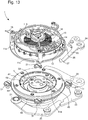
- the multi-part construction of the zeroing device 40 is based on Fig. 4 to 10 clarified.
- the zeroing device 40 has a carrier wheel 41, which centrally has a passage opening 71.
- the carrier wheel 41 has an annular contour.
- the central passage opening 71 is delimited in particular by an inner edge 72, as shown in FIG Fig. 4 is indicated. From the inner edge 72 project over the circumference of the inner edge 72 distributed distributed pawls 45 radially inwardly. These are rotatably or pivotally mounted in the plane of the carrier wheel 41. They are like a comparison of Fig. 4 and 7 clarified, radially inwardly deflectable.
- Each of the pawls 45 has at its free and inwardly projecting end on a Steueranlaufschräge 45 a. At the bottom of the pawls 45, a dome-shaped latch cam 47 is formed in each case. Further, each of the pawls 45 is coupled to a pawl spring 46, by means of which the individual pawls 45 are deflected radially inwardly against a spring force. The radially inwardly directed deflection takes place via an axial force acting on the pawl cams 47. With decreasing force effect, the individual pawl springs 46 cause a movement of the pawls 45 radially outwards, in the in Fig. 4 shown starting position.
- a circulating tire 44 is formed at the radially outer edge of the carrier wheel 41 of the zeroing device 40 at the radially outer edge of the carrier wheel 41 of the zeroing device 40 at the radially outer edge of the carrier wheel 41 of the zeroing device 40 at the radially outer edge of the carrier wheel 41 of the zeroing device 40 at the radially outer edge of the carrier wheel 41 of the zeroing device 40 at the radially outer edge of the carrier wheel 41 of the zeroing device 40 is, as in Fig. 5 shown, on the one hand a circulating tire 44 is formed at the radially offset thereto, the carrier wheel 41 has an external toothing 48. At the top of the carrier wheel 41, a peripheral wheel 42 is arranged. The planet wheel 42 also has an annular contour. On an inner side of the planetary gear 42 is a circumferential internal teeth 49 formed, which, as already mentioned, with the pinion 19 of the balance 15 meshes.
- a stop ring 43 is further attached on the underside of the carrier wheel 41.
- the stop ring 43 has an outer run-on slope 53 on its outer edge.
- the stop ring 43 is mounted axially displaceably on the carrier wheel 41.
- the stop ring 43 further has, as in Fig. 5 shown via a further run-on slope 54 at its inner edge.
- the inner starting bevel 54 of the stop ring 43 can engage with the pawl cams 47.
- An upward axial movement of the stop ring 43 towards the carrier wheel 41 thus causes a radially inwardly directed deflection of the three pawls 45. This is based on a comparison of Fig. 5 and 8th or the Fig. 6 and 9 recognizable.
- the entire zeroing device 40 is rotatably mounted on the circuit board 2 via the circulating tire 44 at a plurality of bearing rollers 31 distributed over the circumference of the zeroing device 40.
- the zeroing device 40 via a fixing element 30, which is configured here as a fixing lever, on the circuit board 2 releasably fixed.
- a free end of the fixing element 30 is frictionally engaged with an outer edge of the zeroing device 40, for example.
- the zeroing device 40 can be released so that it is rotatable relative to the board 2 with respect to a central axis of rotation 73.
- the axis of rotation 73 of the zeroing device 40 may coincide in particular with the balance axis 70 and with the axis of the secondary drive 5.
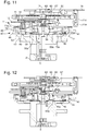
- a brake element 60 On a top side of the lower frame 11a, a brake element 60, in the present case in the form of a flat brake spring, is also arranged.
- the brake element 60 in particular its free and radially inwardly projecting end, is arranged axially movably on the frame 11. It is in particular by means of an axially displaceable in the hub 6 or on the frame 11 brake pin 58 from a starting position, as in Fig. 11 shown in a braking position, as in Fig. 12 shown, deflectable.
- the brake pin 58 is located with a head in a recess of the lower frame 11 a. By an axially upward deflection of the brake pin 58 presses axially on the brake member 60, so that its free end rubbing and in the axial direction with a corresponding thereto configured friction surface of a double roller 62 engages, which is connected to the balance 15. In this way, the balance 15 can be stopped and fixed with respect to the frame 11.
- the brake pin 58 is by means of an axially displaceably mounted brake ring 56 of the in Fig. 11 shown initial or basic position in the in Fig. 12 shown braking position can be transferred.
- the brake ring 56 Radially outward and at the lower end, the brake ring 56 on a run-on slope 56a, which is formed circumferentially and corresponding to the control starting slope 45a of the pawls 45 configured.
- a radially inwardly directed pivoting movement of the pawls 45 thus leads to an upward, in the direction of the frame 11 directed axial displacement of the brake ring 56, whereby the brake pin 58 and hereby also the brake member 60 axially displaced or axially deflected.
- the brake element 60 By the radially inwardly directed pivoting movement of the pawls 45, the brake element 60 finally comes with the double roller 62 of the balance 15 into engagement.
- the axial displacement of the brake ring 56 relative to the hub 6 or relative to the frame 11 takes place counter to the restoring force of a spreading spring 57, which is arranged axially between the hub 6 and the brake ring 56.
- a spreading spring 57 which is arranged axially between the hub 6 and the brake ring 56.
- the pawls 45 under the action of their respective pawl springs 46 back into the in Fig. 4 swung back starting position shown takes place under the action of the spreading spring 57 also equally a movement of the brake ring 56 in his in Fig. 11 shown starting position.
- the balance 15 is released again, causing the stopped movement 1 automatically starts again.
- first and second stop pawls 20, 22 are provided on the outer circumference of the zeroing device 40, as these in Fig. 13 are shown.
- the first stop pawl 20 and second stop pawl 22 are pivotally mounted on the board 2.
- a first run-on slope 21, and a second run-on slope 23 are provided. These are formed for example in the form of conical wheels.
- the respective first and second run-on slopes 21, 23 of the respective first and second stop pawls 20, 22 are located at the level of the outer run-on slope 53 provided on the outer edge of the stop ring 43.
- a radially inwardly directed pivoting of the first and second stop pawls 20, 22 leads to a uniform lifting or axial displacement of the stop ring 43 from the in Fig. 11 shown starting position or basic configuration in the in Fig. 12 illustrated stop configuration.
- the position of the first and second chamfers 21, 23 in the FIGS. 11 and 12 not explicitly shown.
- the axial movement of the stop ring 43 leads, as already described, to the radially inwardly directed deflection of the pawls 45 and thus to an axial displacement of the brake pin 58 and ultimately to the balance 15 lasting deflection of the brake element 60th
- That one stopping of the movement 1 causing synchronous pivotal movement of the two first and second pawls 20, 22 can be done by pulling a crown in a predetermined detent position. The movement 1 is thus stopped. Is the present not explicitly shown crown, starting from that stop configuration in a further, for example, pulled out in a second detent position, this causes a coupled pivoting of the fixing element 30 and a pawl 26th
- the frame 11 is freely rotatably mounted on the board 2. Due to the mutual engagement of pawl 26 and locking cam 28, a defined end stop for the frame 11, thus created for the entire tourbillon unit 10, so that the second hand 18 typically comes to rest on the twelve.
- the fixing element 30 engaging with the zeroing device 40 is deflected radially outward. As a result, the zeroing device 40 is transferred into a release position, so that their rotational fixation is canceled relative to the board 2.
- the coupled movement of pawl 26 and fixing member 30 is via an in Fig. 13 indicated control lever 24 initiated.
- the pivoting movements of the fixing element 30 and the pawl 26 are rigidly coupled together. It is in any case necessary to ensure that the fixing lever 30 can only be transferred to its release position when the pawl 26 is in its locked position.
- the second hand 18 In this axial position of the crown, the second hand 18 thus automatically moves into a well-defined zero position or zero position, without the crown having to be further manipulated.
- the usual interaction of a zeroing lever with a common zero heart is no longer needed.
- the zero position of the secondary pointer 18 is effected by a combined rotational movement of the zeroing device 40 and the tourbillon unit 10 driven by the barrel via the second drive 5, this rotary movement can preferably be damped or braked by means of a separate braking mechanism.
- the braking mechanism not explicitly shown here, for example, can be permanently engaged with the external toothing 48 of the zeroing device 40, for example. That braking device can act, for example, as a rotary damper.
- the rotary damper is realized as a hydraulic damper module which is in engagement with the external toothing 48 of the zeroing device 40 via an intermediate gear.
- both the gear ratios in this transmission chain, as well as the viscosity of the liquid of the hydraulic damper module can be adjusted for an adapted rotational speed.
- the conical first and second chamfers 21, 23 are used in addition to the bearing rollers 31 of the radial and axial bearing of the zeroing device 40 on the board. 2
- the fixing element 30 first comes into frictional engagement with the zeroing device 40 again. Then the pawl 26 is transferred from its rest position back to a starting position. As a result, on the one hand, the zeroing device 40 is again fixed to the board 2, while the frame 11 is disengaged from the pawl 26.
Landscapes
- Physics & Mathematics (AREA)
- General Physics & Mathematics (AREA)
- Braking Arrangements (AREA)
- Electromechanical Clocks (AREA)
Claims (15)
- Mouvement d'horlogerie doté d'un tourbillon, comprenant :- une platine (2),- un châssis (11) relié à un mécanisme secondaire (5), monté de manière à pouvoir tourner au niveau de la platine (2),- un balancier (15) monté au niveau du châssis (11) et une roue d'ancre (12) montée au niveau du châssis (11) et en relation active avec le balancier (15),- un dispositif d'arrêt de balancier (50) pouvant être amené en prise avec le balancier (15), caractérisé en ce qu'il présente en outre un- système de mise à zéro (40) pour l'orientation angulaire du châssis (11).
- Mouvement d'horlogerie selon la revendication 1, dans lequel ledit système de mise à zéro peut être amené en prise de manière solidaire en rotation au choix avec le châssis (11) ou avec la platine (2), et le système de mise à zéro (40) est fixé de manière solidaire en rotation au niveau de la platine (2) dans une configuration de base.
- Mouvement d'horlogerie selon l'une quelconque des revendications précédentes, dans lequel le système de mise à zéro (40) peut être couplé de manière solidaire en rotation au châssis (11) lorsque le balancier (15) est arrêté au moyen du dispositif d'arrêt de balancier (50).
- Mouvement d'horlogerie selon l'une quelconque des revendications précédentes, dans lequel le dispositif d'arrêt de balancier (50) présente un élément de freinage (60) disposé au niveau du châssis rotatif (11) et pouvant être amené en prise par friction avec le balancier (15), mobile de manière axiale par rapport à un axe de balancier (17).
- Mouvement d'horlogerie selon la revendication 4, dans lequel le système de mise à zéro (40) peut être couplé de manière solidaire en rotation au châssis (11) par l'intermédiaire de l'élément de freinage (60).
- Mouvement d'horlogerie selon l'une quelconque des revendications précédentes, dans lequel le système de mise à zéro (40) peut être fixé de manière solidaire en rotation au niveau de la platine (2) au moyen d'un élément de fixation (30), et l'élément de fixation (30) peut être transféré, exclusivement dans le cas d'un couplage solidaire en rotation du châssis (11) et du système de mise à zéro (40), dans une position de déblocage, dans laquelle le système de mise à zéro (40) peut tourner conjointement avec le châssis (11) par rapport à la platine (2).
- Mouvement de d'horlogerie selon l'une quelconque des revendications précédentes, comprenant en outre un loquet de fermeture (26) disposé de manière mobile au niveau de la platine (2), lequel coopère avec une came d'enclenchement (28) disposée au niveau du châssis (11) afin d'arrêter le châssis (11) dans une position zéro.
- Mouvement d'horlogerie selon l'une quelconque des revendications précédentes 6 et 7, dans lequel le loquet de fermeture (26) est couplé à l'élément de fixation (30) et passe dans une position d'enclenchement afin d'arrêter le châssis (11) quand l'élément de fixation (30) passe depuis la position de fixation dans la position de déblocage.
- Mouvement d'horlogerie selon l'une quelconque des revendications précédentes, dans lequel le système de mise à zéro (40) présente une roue de support (41) pourvue d'un pneu périphérique (44) de type jante, qui est monté de manière à pouvoir tourner sur sa périphérie extérieure au niveau d'au moins trois rouleaux de support (31) disposés au niveau de la platine (2).
- Mouvement d'horlogerie selon l'une quelconque des revendications précédentes, dans lequel le système de mise à zéro (40) présente une roue périphérique (42) de type annulaire pourvue d'une denture intérieure (49), qui s'engage avec un pignon (19) de la roue d'ancre (12).
- Mouvement d'horlogerie selon l'une quelconque des revendications 9 ou 10, dans lequel le système de mise à zéro (40) présente une bague d'arrêt (43) mobile de manière axiale par rapport à son axe de rotation, laquelle présente, au niveau d'un bord situé radialement à l'extérieur, un biseau d'attaque (53) extérieur, qui correspond à un respectivement premier ou deuxième biseau d'attaque (21, 23) d'un premier ou deuxième loquet d'arrêt (20, 22) disposé de manière mobile au niveau de la platine (2).
- Mouvement d'horlogerie selon la revendication 11, dans lequel la bague d'arrêt (43) présente, au niveau d'un bord situé radialement à l'intérieur, un biseau d'attaque (54), qui coopère avec au moins une came (47) d'au moins un loquet (45) monté de manière mobile radialement vers l'intérieur au niveau du système de mise à zéro (40) à l'encontre d'une force de rappel.
- Mouvement d'horlogerie selon la revendication 12, dans lequel l'au moins un loquet (45) présente, au niveau de son extrémité située radialement à l'intérieur, un biseau d'attaque de commande (45a), qui peut être amené en prise avec un biseau d'attaque (56a) d'une bague de freinage (56).
- Mouvement d'horlogerie selon la revendication 13, comprenant en outre un boulon de freinage (58), qui est guidé de manière mobile axialement dans un moyeu (6) du tourbillon (10) ou dans le châssis (11) et qui peut être coulissé de manière axiale au moyen de la bague de freinage (56) afin de dévier l'élément de freinage (60) et d'arrêter le balancier (15).
- Montre comprenant un mouvement d'horlogerie (1) selon l'une quelconque des revendications précédentes.
Priority Applications (4)
| Application Number | Priority Date | Filing Date | Title |
|---|---|---|---|
| EP15183133.6A EP3136187B1 (fr) | 2015-08-31 | 2015-08-31 | Montre mecanique dotee d'un tourbillon |
| US15/206,661 US9996054B2 (en) | 2015-08-31 | 2016-07-11 | Mechanical clockwork movement with a tourbillon |
| JP2016155284A JP6279032B2 (ja) | 2015-08-31 | 2016-08-08 | トゥールビヨンを備える機械式のゼンマイ式ムーブメント |
| CN201610796632.2A CN106483817B (zh) | 2015-08-31 | 2016-08-31 | 具有陀飞轮的机械钟表机芯 |
Applications Claiming Priority (1)
| Application Number | Priority Date | Filing Date | Title |
|---|---|---|---|
| EP15183133.6A EP3136187B1 (fr) | 2015-08-31 | 2015-08-31 | Montre mecanique dotee d'un tourbillon |
Publications (2)
| Publication Number | Publication Date |
|---|---|
| EP3136187A1 EP3136187A1 (fr) | 2017-03-01 |
| EP3136187B1 true EP3136187B1 (fr) | 2018-02-28 |
Family
ID=54014636
Family Applications (1)
| Application Number | Title | Priority Date | Filing Date |
|---|---|---|---|
| EP15183133.6A Active EP3136187B1 (fr) | 2015-08-31 | 2015-08-31 | Montre mecanique dotee d'un tourbillon |
Country Status (4)
| Country | Link |
|---|---|
| US (1) | US9996054B2 (fr) |
| EP (1) | EP3136187B1 (fr) |
| JP (1) | JP6279032B2 (fr) |
| CN (1) | CN106483817B (fr) |
Families Citing this family (14)
| Publication number | Priority date | Publication date | Assignee | Title |
|---|---|---|---|---|
| CA2913376C (fr) | 2013-05-24 | 2021-11-02 | Hydrogenics Corporation | Systeme et methode pour controler la tension d'une pile a combustible aumoyen d'une ligne de recirculation |
| EP3396470B1 (fr) * | 2017-04-24 | 2020-01-01 | ETA SA Manufacture Horlogère Suisse | Dispositif de freinage mecanique pour mobile horloger |
| JP1624216S (fr) * | 2017-12-21 | 2019-02-12 | ||
| EP3579058B1 (fr) * | 2018-06-07 | 2021-09-15 | Montres Breguet S.A. | Piece d'horlogerie comprenant un tourbillon |
| EP3588200B1 (fr) * | 2018-06-29 | 2021-10-06 | Glashütter Uhrenbetrieb GmbH | Tourbillon avec mécanisme de remise à zéro |
| FR3087906B1 (fr) * | 2018-10-24 | 2020-11-20 | Watch Connaisseur Project Sa | Dispositif d'arret de systeme oscillant |
| EP3770695B1 (fr) * | 2019-07-23 | 2022-01-12 | Omega SA | Stop-cage d'horlogerie a lame d'arrêt de cage |
| EP3770694B1 (fr) * | 2019-07-23 | 2021-12-08 | Omega SA | Stop-cage d'horlogerie comportant deux elements elastiques d'arret |
| EP3770696B1 (fr) * | 2019-07-23 | 2021-12-01 | Omega SA | Stop-cage d'horlogerie a doigt elevateur et doigt d'arret |
| EP3770693B1 (fr) * | 2019-07-23 | 2022-08-31 | Omega SA | Mecanisme stop-cage d'horlogerie a roue d'arret |
| EP3979007A1 (fr) * | 2020-10-02 | 2022-04-06 | Montres Breguet S.A. | Montre à mouvement mécanique à mécanisme de contrôle de force |
| CN112305894B (zh) * | 2020-10-28 | 2022-04-26 | 深圳市格雅表业有限公司 | 一种机械钟表机芯中的陀飞轮 |
| CH718188A1 (fr) | 2020-12-17 | 2022-06-30 | Mft Dhorlogerie Audemars Piguet Sa | Mouvement mécanique comprenant un dispositif d'affichage de l'heure. |
| EP4047425A1 (fr) * | 2021-02-19 | 2022-08-24 | Montres Breguet S.A. | Dispositif pour effectuer un arrêt momentané du fonctionnement d'une montre mécanique |
Family Cites Families (14)
| Publication number | Priority date | Publication date | Assignee | Title |
|---|---|---|---|---|
| DE10160287A1 (de) | 2001-12-07 | 2003-06-26 | Lange Uhren Gmbh | Tourbillon |
| EP1617305B1 (fr) * | 2004-07-13 | 2009-01-21 | Montres Breguet S.A. | Dispositif d'arrêt pendant la mise à l'heure d'une montre équipée d'un tourbillon |
| DE102006008699B3 (de) * | 2006-02-24 | 2007-08-23 | Heitzer, Heinz-Dieter, Dr. | Einstellvorrichtung für die Justierung der Zeigerstellung bei mechanischen Uhren |
| EP1840677B1 (fr) | 2006-03-28 | 2011-10-26 | Chopard Manufacture SA | Remise à zéro de l'aiguille des secondes dans une pièce d'horlogerie |
| CH701725B1 (fr) * | 2006-09-25 | 2011-03-15 | Franck Mueller Watchland S A | Tourbillon pour pièce d'horlogerie. |
| CH702707B1 (fr) * | 2007-04-05 | 2011-08-31 | Complitime Sa | Mouvement de pièce d'horlogerie à tourbillon. |
| EP2224294B1 (fr) | 2009-02-27 | 2014-09-10 | Glashütter Uhrenbetrieb GmbH | Mécanisme de réglage de l'aiguille des minutes d'une montre avec remise à zéro automatique de l'aiguille des secondes |
| DE102009017714A1 (de) * | 2009-04-09 | 2011-01-13 | Takata-Petri Ag | Lenkrad für ein Kraftfahrzeug mit Überlagerungslenkung |
| EP2397920A1 (fr) * | 2010-06-17 | 2011-12-21 | Blancpain S.A. | Mécanisme d'avance par saut périodique d'une cage de tourbillon ou d'une cage de carrousel |
| EP2397921B1 (fr) * | 2010-06-17 | 2017-08-30 | Blancpain S.A. | Mécanisme d'avance par saut périodique d'une cage de carrousel |
| EP2450757B1 (fr) * | 2010-11-04 | 2014-10-15 | Nivarox-FAR S.A. | Dispositif anti-galop pour mécanisme d'échappement |
| ES2593815T3 (es) * | 2013-04-03 | 2016-12-13 | Chopard Technologies Sa | Movimiento de relojería con torbellino y con mecanismo de parada de volante |
| EP2793087B1 (fr) * | 2013-04-18 | 2016-06-01 | Glashütter Uhrenbetrieb GmbH | Tourbillon |
| EP3029530B1 (fr) * | 2014-12-03 | 2019-08-14 | Nivarox-FAR S.A. | Mécanisme de tourbillon |
-
2015
- 2015-08-31 EP EP15183133.6A patent/EP3136187B1/fr active Active
-
2016
- 2016-07-11 US US15/206,661 patent/US9996054B2/en active Active
- 2016-08-08 JP JP2016155284A patent/JP6279032B2/ja active Active
- 2016-08-31 CN CN201610796632.2A patent/CN106483817B/zh active Active
Non-Patent Citations (1)
| Title |
|---|
| None * |
Also Published As
| Publication number | Publication date |
|---|---|
| CN106483817A (zh) | 2017-03-08 |
| US20170060091A1 (en) | 2017-03-02 |
| US9996054B2 (en) | 2018-06-12 |
| EP3136187A1 (fr) | 2017-03-01 |
| JP2017049236A (ja) | 2017-03-09 |
| CN106483817B (zh) | 2019-03-19 |
| JP6279032B2 (ja) | 2018-02-14 |
Similar Documents
| Publication | Publication Date | Title |
|---|---|---|
| EP3136187B1 (fr) | Montre mecanique dotee d'un tourbillon | |
| EP3136186B1 (fr) | Montre mecanique dotee de tourbillon reglable | |
| EP2793087B1 (fr) | Tourbillon | |
| CH701995B1 (de) | Uhrwerkslager und Uhrwerk sowie tragbarer Zeitmesser. | |
| WO2009059441A1 (fr) | Montre-bracelet mécanique à force de ressort constante | |
| DE2319907A1 (de) | Kalender-schaltvorrichtung fuer uhren | |
| CH703212A2 (de) | Kalendermechanismus und damit ausgestatteter Zeitmesser. | |
| DE2707976C2 (de) | Reibungsschaltkupplung, insb. für Kraftfahrzeuge | |
| DE2207513A1 (de) | Korrekturvorrichtung für die kalendarische Anzeige eines Zeitmessers | |
| CH711477A2 (de) | Mechanisches Uhrwerk mit einem einstellbaren Tourbillon. | |
| DE2136528C3 (de) | Uhr mit einer Einstell- und Aufzieheinrichtung | |
| DE10155146B4 (de) | Vorrichtung zur automatischen Verschleißnachstellung in einer Reibungskupplung, insbesondere für Kraftfahrzeuge | |
| CH711476A2 (de) | Mechanisches Uhrwerk mit einem Tourbillon. | |
| DE2430122A1 (de) | Uhr mit automatischem aufzug | |
| DE2104577C3 (de) | Uhrwerk | |
| DE2329176A1 (de) | Aufzieh- und einstellvorrichtung fuer uhren | |
| CH707928A2 (de) | Tourbillon. | |
| DE2421434C3 (de) | Stellmechanismus für den Stundenzeiger und einen HilfsStundenzeiger einer Uhr | |
| EP0147757A1 (fr) | Minuterie avec dispositif mécanique permettant le réglage de l'aiguille des heures par pas d'une demi-heure ainsi que la correction de l'aiguille des secondes | |
| CH566867A5 (fr) | ||
| DE2303926C3 (de) | Uhrwerk mit einer automatischen Aufzugsvorrichtung, einem in der Mitte des Werkes gelagerten Sekundenrad und mit einem exzentrisch gelagerten Großbodenrad | |
| DE1015747B (de) | Differentialgetriebe fuer die UEberwachung der Federspannung in Uhren | |
| DE2438684C3 (de) | Mitnehmermechanismus für ein springendes Umlauforgan in Uhrwerken | |
| DE2421434B2 (de) | Stellmechanismus für den Stundenzeiger und einen Hilfsstundenzeiger einer Uhr | |
| CH700819B1 (de) | Uhrengehäuse. |
Legal Events
| Date | Code | Title | Description |
|---|---|---|---|
| PUAI | Public reference made under article 153(3) epc to a published international application that has entered the european phase |
Free format text: ORIGINAL CODE: 0009012 |
|
| AK | Designated contracting states |
Kind code of ref document: A1 Designated state(s): AL AT BE BG CH CY CZ DE DK EE ES FI FR GB GR HR HU IE IS IT LI LT LU LV MC MK MT NL NO PL PT RO RS SE SI SK SM TR |
|
| AX | Request for extension of the european patent |
Extension state: BA ME |
|
| 17P | Request for examination filed |
Effective date: 20170901 |
|
| RBV | Designated contracting states (corrected) |
Designated state(s): AL AT BE BG CH CY CZ DE DK EE ES FI FR GB GR HR HU IE IS IT LI LT LU LV MC MK MT NL NO PL PT RO RS SE SI SK SM TR |
|
| GRAP | Despatch of communication of intention to grant a patent |
Free format text: ORIGINAL CODE: EPIDOSNIGR1 |
|
| INTG | Intention to grant announced |
Effective date: 20171107 |
|
| GRAS | Grant fee paid |
Free format text: ORIGINAL CODE: EPIDOSNIGR3 |
|
| GRAA | (expected) grant |
Free format text: ORIGINAL CODE: 0009210 |
|
| AK | Designated contracting states |
Kind code of ref document: B1 Designated state(s): AL AT BE BG CH CY CZ DE DK EE ES FI FR GB GR HR HU IE IS IT LI LT LU LV MC MK MT NL NO PL PT RO RS SE SI SK SM TR |
|
| REG | Reference to a national code |
Ref country code: GB Ref legal event code: FG4D Free format text: NOT ENGLISH Ref country code: CH Ref legal event code: EP |
|
| REG | Reference to a national code |
Ref country code: AT Ref legal event code: REF Ref document number: 974788 Country of ref document: AT Kind code of ref document: T Effective date: 20180315 |
|
| REG | Reference to a national code |
Ref country code: IE Ref legal event code: FG4D Free format text: LANGUAGE OF EP DOCUMENT: GERMAN |
|
| REG | Reference to a national code |
Ref country code: DE Ref legal event code: R096 Ref document number: 502015003181 Country of ref document: DE |
|
| REG | Reference to a national code |
Ref country code: NL Ref legal event code: MP Effective date: 20180228 |
|
| REG | Reference to a national code |
Ref country code: LT Ref legal event code: MG4D |
|
| REG | Reference to a national code |
Ref country code: FR Ref legal event code: PLFP Year of fee payment: 4 |
|
| PG25 | Lapsed in a contracting state [announced via postgrant information from national office to epo] |
Ref country code: NO Free format text: LAPSE BECAUSE OF FAILURE TO SUBMIT A TRANSLATION OF THE DESCRIPTION OR TO PAY THE FEE WITHIN THE PRESCRIBED TIME-LIMIT Effective date: 20180528 Ref country code: FI Free format text: LAPSE BECAUSE OF FAILURE TO SUBMIT A TRANSLATION OF THE DESCRIPTION OR TO PAY THE FEE WITHIN THE PRESCRIBED TIME-LIMIT Effective date: 20180228 Ref country code: NL Free format text: LAPSE BECAUSE OF FAILURE TO SUBMIT A TRANSLATION OF THE DESCRIPTION OR TO PAY THE FEE WITHIN THE PRESCRIBED TIME-LIMIT Effective date: 20180228 Ref country code: CY Free format text: LAPSE BECAUSE OF FAILURE TO SUBMIT A TRANSLATION OF THE DESCRIPTION OR TO PAY THE FEE WITHIN THE PRESCRIBED TIME-LIMIT Effective date: 20180228 Ref country code: HR Free format text: LAPSE BECAUSE OF FAILURE TO SUBMIT A TRANSLATION OF THE DESCRIPTION OR TO PAY THE FEE WITHIN THE PRESCRIBED TIME-LIMIT Effective date: 20180228 Ref country code: ES Free format text: LAPSE BECAUSE OF FAILURE TO SUBMIT A TRANSLATION OF THE DESCRIPTION OR TO PAY THE FEE WITHIN THE PRESCRIBED TIME-LIMIT Effective date: 20180228 Ref country code: LT Free format text: LAPSE BECAUSE OF FAILURE TO SUBMIT A TRANSLATION OF THE DESCRIPTION OR TO PAY THE FEE WITHIN THE PRESCRIBED TIME-LIMIT Effective date: 20180228 |
|
| REG | Reference to a national code |
Ref country code: CH Ref legal event code: NV Representative=s name: ICB INGENIEURS CONSEILS EN BREVETS SA, CH |
|
| PG25 | Lapsed in a contracting state [announced via postgrant information from national office to epo] |
Ref country code: GR Free format text: LAPSE BECAUSE OF FAILURE TO SUBMIT A TRANSLATION OF THE DESCRIPTION OR TO PAY THE FEE WITHIN THE PRESCRIBED TIME-LIMIT Effective date: 20180529 Ref country code: RS Free format text: LAPSE BECAUSE OF FAILURE TO SUBMIT A TRANSLATION OF THE DESCRIPTION OR TO PAY THE FEE WITHIN THE PRESCRIBED TIME-LIMIT Effective date: 20180228 Ref country code: BG Free format text: LAPSE BECAUSE OF FAILURE TO SUBMIT A TRANSLATION OF THE DESCRIPTION OR TO PAY THE FEE WITHIN THE PRESCRIBED TIME-LIMIT Effective date: 20180528 Ref country code: SE Free format text: LAPSE BECAUSE OF FAILURE TO SUBMIT A TRANSLATION OF THE DESCRIPTION OR TO PAY THE FEE WITHIN THE PRESCRIBED TIME-LIMIT Effective date: 20180228 Ref country code: LV Free format text: LAPSE BECAUSE OF FAILURE TO SUBMIT A TRANSLATION OF THE DESCRIPTION OR TO PAY THE FEE WITHIN THE PRESCRIBED TIME-LIMIT Effective date: 20180228 |
|
| PG25 | Lapsed in a contracting state [announced via postgrant information from national office to epo] |
Ref country code: MT Free format text: LAPSE BECAUSE OF FAILURE TO SUBMIT A TRANSLATION OF THE DESCRIPTION OR TO PAY THE FEE WITHIN THE PRESCRIBED TIME-LIMIT Effective date: 20180228 |
|
| PG25 | Lapsed in a contracting state [announced via postgrant information from national office to epo] |
Ref country code: PL Free format text: LAPSE BECAUSE OF FAILURE TO SUBMIT A TRANSLATION OF THE DESCRIPTION OR TO PAY THE FEE WITHIN THE PRESCRIBED TIME-LIMIT Effective date: 20180228 Ref country code: EE Free format text: LAPSE BECAUSE OF FAILURE TO SUBMIT A TRANSLATION OF THE DESCRIPTION OR TO PAY THE FEE WITHIN THE PRESCRIBED TIME-LIMIT Effective date: 20180228 Ref country code: RO Free format text: LAPSE BECAUSE OF FAILURE TO SUBMIT A TRANSLATION OF THE DESCRIPTION OR TO PAY THE FEE WITHIN THE PRESCRIBED TIME-LIMIT Effective date: 20180228 Ref country code: IT Free format text: LAPSE BECAUSE OF FAILURE TO SUBMIT A TRANSLATION OF THE DESCRIPTION OR TO PAY THE FEE WITHIN THE PRESCRIBED TIME-LIMIT Effective date: 20180228 Ref country code: AL Free format text: LAPSE BECAUSE OF FAILURE TO SUBMIT A TRANSLATION OF THE DESCRIPTION OR TO PAY THE FEE WITHIN THE PRESCRIBED TIME-LIMIT Effective date: 20180228 |
|
| REG | Reference to a national code |
Ref country code: DE Ref legal event code: R097 Ref document number: 502015003181 Country of ref document: DE |
|
| PG25 | Lapsed in a contracting state [announced via postgrant information from national office to epo] |
Ref country code: SK Free format text: LAPSE BECAUSE OF FAILURE TO SUBMIT A TRANSLATION OF THE DESCRIPTION OR TO PAY THE FEE WITHIN THE PRESCRIBED TIME-LIMIT Effective date: 20180228 Ref country code: SM Free format text: LAPSE BECAUSE OF FAILURE TO SUBMIT A TRANSLATION OF THE DESCRIPTION OR TO PAY THE FEE WITHIN THE PRESCRIBED TIME-LIMIT Effective date: 20180228 Ref country code: DK Free format text: LAPSE BECAUSE OF FAILURE TO SUBMIT A TRANSLATION OF THE DESCRIPTION OR TO PAY THE FEE WITHIN THE PRESCRIBED TIME-LIMIT Effective date: 20180228 Ref country code: CZ Free format text: LAPSE BECAUSE OF FAILURE TO SUBMIT A TRANSLATION OF THE DESCRIPTION OR TO PAY THE FEE WITHIN THE PRESCRIBED TIME-LIMIT Effective date: 20180228 |
|
| PLBE | No opposition filed within time limit |
Free format text: ORIGINAL CODE: 0009261 |
|
| STAA | Information on the status of an ep patent application or granted ep patent |
Free format text: STATUS: NO OPPOSITION FILED WITHIN TIME LIMIT |
|
| 26N | No opposition filed |
Effective date: 20181129 |
|
| PG25 | Lapsed in a contracting state [announced via postgrant information from national office to epo] |
Ref country code: SI Free format text: LAPSE BECAUSE OF FAILURE TO SUBMIT A TRANSLATION OF THE DESCRIPTION OR TO PAY THE FEE WITHIN THE PRESCRIBED TIME-LIMIT Effective date: 20180228 |
|
| PG25 | Lapsed in a contracting state [announced via postgrant information from national office to epo] |
Ref country code: MC Free format text: LAPSE BECAUSE OF FAILURE TO SUBMIT A TRANSLATION OF THE DESCRIPTION OR TO PAY THE FEE WITHIN THE PRESCRIBED TIME-LIMIT Effective date: 20180228 |
|
| PG25 | Lapsed in a contracting state [announced via postgrant information from national office to epo] |
Ref country code: LU Free format text: LAPSE BECAUSE OF NON-PAYMENT OF DUE FEES Effective date: 20180831 |
|
| REG | Reference to a national code |
Ref country code: BE Ref legal event code: MM Effective date: 20180831 |
|
| PG25 | Lapsed in a contracting state [announced via postgrant information from national office to epo] |
Ref country code: BE Free format text: LAPSE BECAUSE OF NON-PAYMENT OF DUE FEES Effective date: 20180831 |
|
| PG25 | Lapsed in a contracting state [announced via postgrant information from national office to epo] |
Ref country code: TR Free format text: LAPSE BECAUSE OF FAILURE TO SUBMIT A TRANSLATION OF THE DESCRIPTION OR TO PAY THE FEE WITHIN THE PRESCRIBED TIME-LIMIT Effective date: 20180228 |
|
| PG25 | Lapsed in a contracting state [announced via postgrant information from national office to epo] |
Ref country code: PT Free format text: LAPSE BECAUSE OF FAILURE TO SUBMIT A TRANSLATION OF THE DESCRIPTION OR TO PAY THE FEE WITHIN THE PRESCRIBED TIME-LIMIT Effective date: 20180228 |
|
| PG25 | Lapsed in a contracting state [announced via postgrant information from national office to epo] |
Ref country code: IE Free format text: LAPSE BECAUSE OF NON-PAYMENT OF DUE FEES Effective date: 20180831 Ref country code: MK Free format text: LAPSE BECAUSE OF NON-PAYMENT OF DUE FEES Effective date: 20180228 Ref country code: HU Free format text: LAPSE BECAUSE OF FAILURE TO SUBMIT A TRANSLATION OF THE DESCRIPTION OR TO PAY THE FEE WITHIN THE PRESCRIBED TIME-LIMIT; INVALID AB INITIO Effective date: 20150831 |
|
| PG25 | Lapsed in a contracting state [announced via postgrant information from national office to epo] |
Ref country code: IS Free format text: LAPSE BECAUSE OF FAILURE TO SUBMIT A TRANSLATION OF THE DESCRIPTION OR TO PAY THE FEE WITHIN THE PRESCRIBED TIME-LIMIT Effective date: 20180628 |
|
| REG | Reference to a national code |
Ref country code: AT Ref legal event code: MM01 Ref document number: 974788 Country of ref document: AT Kind code of ref document: T Effective date: 20200831 |
|
| PG25 | Lapsed in a contracting state [announced via postgrant information from national office to epo] |
Ref country code: AT Free format text: LAPSE BECAUSE OF NON-PAYMENT OF DUE FEES Effective date: 20200831 |
|
| P01 | Opt-out of the competence of the unified patent court (upc) registered |
Effective date: 20230531 |
|
| PGFP | Annual fee paid to national office [announced via postgrant information from national office to epo] |
Ref country code: DE Payment date: 20250724 Year of fee payment: 11 |
|
| PGFP | Annual fee paid to national office [announced via postgrant information from national office to epo] |
Ref country code: GB Payment date: 20250725 Year of fee payment: 11 |
|
| PGFP | Annual fee paid to national office [announced via postgrant information from national office to epo] |
Ref country code: FR Payment date: 20250725 Year of fee payment: 11 |
|
| PGFP | Annual fee paid to national office [announced via postgrant information from national office to epo] |
Ref country code: CH Payment date: 20250901 Year of fee payment: 11 |