EP3142039A2 - Self-service terminal with card reader and method for monitoring - Google Patents
Self-service terminal with card reader and method for monitoring Download PDFInfo
- Publication number
- EP3142039A2 EP3142039A2 EP16187750.1A EP16187750A EP3142039A2 EP 3142039 A2 EP3142039 A2 EP 3142039A2 EP 16187750 A EP16187750 A EP 16187750A EP 3142039 A2 EP3142039 A2 EP 3142039A2
- Authority
- EP
- European Patent Office
- Prior art keywords
- card
- sensor
- reading device
- card reading
- self
- Prior art date
- Legal status (The legal status is an assumption and is not a legal conclusion. Google has not performed a legal analysis and makes no representation as to the accuracy of the status listed.)
- Granted
Links
Images


Classifications
-
- G—PHYSICS
- G07—CHECKING-DEVICES
- G07F—COIN-FREED OR LIKE APPARATUS
- G07F19/00—Complete banking systems; Coded card-freed arrangements adapted for dispensing or receiving monies or the like and posting such transactions to existing accounts, e.g. automatic teller machines
- G07F19/20—Automatic teller machines [ATMs]
- G07F19/204—Loading of a stored value token using an ATM
-
- G—PHYSICS
- G06—COMPUTING OR CALCULATING; COUNTING
- G06K—GRAPHICAL DATA READING; PRESENTATION OF DATA; RECORD CARRIERS; HANDLING RECORD CARRIERS
- G06K13/00—Conveying record carriers from one station to another, e.g. from stack to punching mechanism
- G06K13/02—Conveying record carriers from one station to another, e.g. from stack to punching mechanism the record carrier having longitudinal dimension comparable with transverse dimension, e.g. punched card
- G06K13/08—Feeding or discharging cards
- G06K13/0868—Feeding or discharging cards using an arrangement for keeping the feeding or insertion slot of the card station clean of dirt, or to avoid feeding of foreign or unwanted objects into the slot
- G06K13/0875—Feeding or discharging cards using an arrangement for keeping the feeding or insertion slot of the card station clean of dirt, or to avoid feeding of foreign or unwanted objects into the slot the arrangement comprising a shutter for blocking at least part of the card insertion slot
-
- G—PHYSICS
- G06—COMPUTING OR CALCULATING; COUNTING
- G06K—GRAPHICAL DATA READING; PRESENTATION OF DATA; RECORD CARRIERS; HANDLING RECORD CARRIERS
- G06K7/00—Methods or arrangements for sensing record carriers, e.g. for reading patterns
- G06K7/08—Methods or arrangements for sensing record carriers, e.g. for reading patterns by means detecting the change of an electrostatic or magnetic field, e.g. by detecting change of capacitance between electrodes
- G06K7/082—Methods or arrangements for sensing record carriers, e.g. for reading patterns by means detecting the change of an electrostatic or magnetic field, e.g. by detecting change of capacitance between electrodes using inductive or magnetic sensors
- G06K7/083—Methods or arrangements for sensing record carriers, e.g. for reading patterns by means detecting the change of an electrostatic or magnetic field, e.g. by detecting change of capacitance between electrodes using inductive or magnetic sensors inductive
- G06K7/084—Methods or arrangements for sensing record carriers, e.g. for reading patterns by means detecting the change of an electrostatic or magnetic field, e.g. by detecting change of capacitance between electrodes using inductive or magnetic sensors inductive sensing magnetic material by relative movement detecting flux changes without altering its magnetised state
-
- G—PHYSICS
- G06—COMPUTING OR CALCULATING; COUNTING
- G06Q—INFORMATION AND COMMUNICATION TECHNOLOGY [ICT] SPECIALLY ADAPTED FOR ADMINISTRATIVE, COMMERCIAL, FINANCIAL, MANAGERIAL OR SUPERVISORY PURPOSES; SYSTEMS OR METHODS SPECIALLY ADAPTED FOR ADMINISTRATIVE, COMMERCIAL, FINANCIAL, MANAGERIAL OR SUPERVISORY PURPOSES, NOT OTHERWISE PROVIDED FOR
- G06Q20/00—Payment architectures, schemes or protocols
- G06Q20/08—Payment architectures
- G06Q20/10—Payment architectures specially adapted for electronic funds transfer [EFT] systems; specially adapted for home banking systems
- G06Q20/108—Remote banking, e.g. home banking
- G06Q20/1085—Remote banking, e.g. home banking involving automatic teller machines [ATMs]
-
- G—PHYSICS
- G06—COMPUTING OR CALCULATING; COUNTING
- G06Q—INFORMATION AND COMMUNICATION TECHNOLOGY [ICT] SPECIALLY ADAPTED FOR ADMINISTRATIVE, COMMERCIAL, FINANCIAL, MANAGERIAL OR SUPERVISORY PURPOSES; SYSTEMS OR METHODS SPECIALLY ADAPTED FOR ADMINISTRATIVE, COMMERCIAL, FINANCIAL, MANAGERIAL OR SUPERVISORY PURPOSES, NOT OTHERWISE PROVIDED FOR
- G06Q20/00—Payment architectures, schemes or protocols
- G06Q20/30—Payment architectures, schemes or protocols characterised by the use of specific devices or networks
- G06Q20/34—Payment architectures, schemes or protocols characterised by the use of specific devices or networks using cards, e.g. integrated circuit [IC] cards or magnetic cards
-
- G—PHYSICS
- G07—CHECKING-DEVICES
- G07F—COIN-FREED OR LIKE APPARATUS
- G07F19/00—Complete banking systems; Coded card-freed arrangements adapted for dispensing or receiving monies or the like and posting such transactions to existing accounts, e.g. automatic teller machines
- G07F19/20—Automatic teller machines [ATMs]
- G07F19/205—Housing aspects of ATMs
- G07F19/2055—Anti-skimming aspects at ATMs
-
- G—PHYSICS
- G07—CHECKING-DEVICES
- G07F—COIN-FREED OR LIKE APPARATUS
- G07F7/00—Mechanisms actuated by objects other than coins to free or to actuate vending, hiring, coin or paper currency dispensing or refunding apparatus
- G07F7/08—Mechanisms actuated by objects other than coins to free or to actuate vending, hiring, coin or paper currency dispensing or refunding apparatus by coded identity card or credit card or other personal identification means
- G07F7/0873—Details of the card reader
Definitions
- the invention relates to a card reading device for a self-service terminal, in particular for an ATM, according to the preamble of claim 1. Furthermore, the invention relates to a thus equipped self-service terminal and a method for monitoring the same according to the preamble of the independent claims.
- Self-service terminals also known as self-service terminals for short, often use the card readers installed in them as a primary target for manipulation attempts and skimming attacks.
- self-service terminals in particular of ATMs, the user or customer requires a bank card, which usually has a chip and a magnetic strip on which card data including the personal customer and account access data are stored.
- self-service terminals are increasingly being manipulated by third parties to fraudulently access these map data.
- an attempt is made inter alia to insert into the card slot of the card reading device as unobtrusively as possible a special spying device which is suitable for directly reading out the magnetic stripe or for docking to an internal / device-specific data interface (eg USB interface) of the card reading device.
- an internal / device-specific data interface eg USB interface
- skimming tests are known in which a foreign card reader is installed in front of the card slot as an inconspicuous superstructure, which, for example, forwards the read-out card data to the fraudster by radio.
- the fraudster manages to spy on the PIN belonging to the bank card, he can with the fake bank card and the spied pin effortlessly withdraw money from the associated account at ATMs.
- skimming attacks which try to simulate a Schwlesevorgang directly via the internal interface and to manipulate the software control of the self-service terminals or ATMs.
- getting hold of the card is a well-known attack scenario.
- card trapping a stem to steal the card in front of the card reader is mounted.
- This stem is provided to the card reader with a loop, directly behind the card slot of the stem is also a flap that allows only a unidirectional insertion of the card.
- the flap prevents ejection of the card.
- the device user is taught by the behavior of the device, a withdrawal of the card. He leaves the self-service device. Subsequently the thief removes the card including the stem.
- a protective device which has a protective field generator and an associated inductance for generating an electromagnetic protective field, which covers the electromagnetic fields generated during card reading and thus affects the function of the foreign card reader (spy), so that they no longer provide useful data can.
- the electromagnetic protective field is generated with a special protection signal, which is a normal card reading signal simulated, the signal contains only useless pseudo-data that can not be used by the fraudster.
- the protection device is not suitable for preventing or hindering skimming attempts which start directly inside the card reading device and, for example, receive signals from an espying device inserted there or even pick up from an internal device-specific data interface.
- the DE 10 2009 019 708 A1 may be mentioned, which proposes to generate an interference field by means of permanent magnets, which are moved mechanically via piezo elements, so that an alternating magnetic field is formed, which effectively disturbs the skimming card reader when reading cards.
- the EP 1 394 728 A1 to name by using ultrasonic sensors detects whether superstructures are attached to the self-service terminal.
- the conventional self-service terminals are equipped with a card reading device into which a card can be inserted, on which data to be read are stored, to defend against manipulation attempts the self-service terminal itself at least one sensor and an associated evaluation device can be equipped.
- these solutions are not suitable for effective defense against manipulation attempts, which are aimed at the interior of the card reading device.
- the object is achieved by a card reading device having the features of claim 1 and by a self-service terminal and a method having the features of the correspondingly independent claim.
- a card reading device in which the at least one sensor system is arranged in the card reading device and comprises at least one linearly extending sensor arrangement, wherein the evaluation device checks at least one spatial dimension of the card by means of the at least one sensor arrangement.
- a card reading device is presented in which the at least one sensor is arranged in the card reading device itself and is preferably arranged in or on a receiving space for the cards to be read, wherein the evaluation device by means of at least one sensor arrangement at least one spatial dimension of the card, in particular whose width and / or length, checked.
- sensor arrangements for example, opto-electrical sensor strips can be used.
- the invention also provides a self-service terminal, in particular an ATM, with such a card reading device.
- a method is presented here, with which a monitoring of the self-service terminal or ATM is performed by means of the sensor and the evaluation device, wherein the sensor is arranged in the card reading device and at least one linearly extending Sensor arrangement comprises, which is preferably arranged in the receiving space, and wherein at least one spatial dimension of the card is checked by means of the evaluation device and the at least one sensor arrangement.
- a sensor system is installed in the interior of the card reading device in order to check the inserted object located there in the spatial dimensions of a normal card, so that it can be very effectively recognized whether a normal card is actually present in the card reading device or a foreign object, for example. such as a card-like sized spying device.
- the at least one sensor arrangement is formed as a sensor bar, which has a plurality of linearly arranged sensor elements, wherein the sensor bar extends in the longitudinal or transverse direction to the inserted card.
- a first sensor strip can detect the length of the card as a first spatial dimension and / or a second sensor strip can detect the width of the card as a second spatial dimension.
- the second sensor bar is designed so that not only detects the width of the card, but also detects the length of the card by the second sensor bar detects when inserting the card whose beginning and end and by the evaluation by means of a time measurement and by a given Insertion speed determines the length of the card.
- the respective sensor arrangement installed in the card reading device is preferably designed as a sensor strip with a plurality of linearly arranged sensor elements which extend in the longitudinal or transverse direction of the card inserted into the receiving space.
- a first sensor strip detects the length of the card as the first spatial dimension and / or detects a second sensor bar, the width of the card as a second spatial dimension.
- a first additional sensor system can be arranged, which detects the height of the card as a third dimension.
- the sensor elements are the at least one Sensor arrangement and / or the first additional sensor as opto-electrical sensor elements formed. Alternatively, however, other sensor types can be used with which the spatial map dimensions can be detected.
- a further additional sensor system may be provided, in particular optoelectrical sensor system which is arranged in the vicinity of the surface of the card to check material properties of the card, in particular by discrete spectroscopy.
- an additional sensor system in particular a light barrier, is arranged on a catchment area, in particular a storage compartment (retract compartment), which is connected to the at least one evaluation device and which in particular has one or more optoelectronic sensors. having electrical sensor elements to detect tampering with the feeder area.
- the card reading device can thus be configured further such that a further additional sensor system, which is connected to the at least one evaluation device and in particular one or more, is arranged at the catchment area (so-called retract area) for cards to be kept Sensor elements to detect tampering with the feeder area.
- These sensor elements are also preferably opto-electrical components for a light barrier, but may also be other components or sensor types with which the area can be monitored.
- the card reading device which usually has a housing and / or a receiving space into which the card is retractable, can be configured such that the at least one evaluation device is connected to mechatronic transducers, in particular piezoelectric transducers, comprising sensors and / or actuators is, wherein the mechatronic transducers are arranged in or on the housing and / or receiving space, that the integrity of the card reading device, in particular of the housing and / or receiving space is testable, wherein the evaluation device is adapted to receive a signal from the mechatronic transducers which is excited by a part of the mechatronic transducers and is detected by a part of the mechatronic transducers in order to compare this with reference data, and to output at a defined deviation a warning signal which represents a lack of integrity of the card reading device.
- mechatronic transducers in particular piezoelectric transducers, comprising sensors and / or actuators
- the mechatronic transducers are arranged in or on the housing and
- the card reading device in or mechatronic transducers may be provided at the receiving space of the card reading device, in particular piezoelectric electrical transducers, comprising sensors and / or actuators, which are connected to an evaluation device.
- These transducers are intended to exert a vibration, preferably in the audible sound range or natural frequency range, on the card reading device in order to check the integrity of the card reading device, in particular of the housing and / or receiving space.
- the evaluation device manages eg reference data from the mechatronic transducers, which represent a permissible state of the recording space.
- the mechatronic transducers can also be arranged in a sensor field (patch).
- the sensor field preferably comprises a plurality of sound-electric, in particular a plurality of piezoelectric electrical sensor elements.
- a sensor field could also be fixed in or on the receiving space of the card reading device, preferably parallel to a surface of the card, in order also to check the material properties of the card in this way.
- individual elements of the sensor field act as actuators, in particular piezoelectric actuators, which stimulate the region of the card reading device to vibrate, so that the signals to be evaluated are generated by the other sensor elements of the sensor field. Accordingly, the evaluation could be extended so that they not only evaluate the signals from the opto-electrical sensor strips, but also the signals coming from other sensor elements, in particular from the sensor elements of the mechatronic sensor array.
- FIGS. 1a and 1b schematically the construction of a card reading device 20 is shown, which has a receiving space 13 for a card to be read 11 inside.
- the receiving space 13 also comprises the actual card reader 3 or card reading elements, which comprise, for example, a contact station for reading out card chips and a read head for reading out magnetic strips.
- the card to be read 11 or 11 ' is transported in a conventional manner via transport from the insertion slot into the receiving space 13 to be optimally positioned there to the card reading elements for the read-out. For this customary guiding and stop elements can be provided.
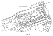
- card reader is here the overall arrangement (s. Fig. 1b ), which include the housing 1, base plate 2, card reader 3, if necessary. IDKG insert 5, additive sensors 6, esp. Light barrier (s) or sensor strip (s), optional camera 10 and card transport may include. Depending on the equipment, fewer components may be installed. Under card reader is here essentially understood the device 3, which is provided for the actual reading of the map data.
- the housing 1 encloses in conjunction with the base plate 2 the Karenleser 3 completely.
- the transducer elements are mounted on / in the housing 1; In principle, however, the arrangement is also conceivable on all other individual components. For this purpose, it makes sense to make a superposition of the modal strains in the frequency ranges to be considered. Significant and therefore well suited Postions are thereby visualized.
- the transducer positioning can be done.
- the only openings of the housing are the opening for card insertion (IDKG insert 5) and the associated detection by the additive sensors 6 and the breakthrough for retracted cards, which is monitored by a light barrier 7.
- the card reader 20 in its rear part also on an area 8, which is provided for the retention of cards 11, which should not be returned to the user due to unfulfilled conditions of the self-service terminal.
- the tray 8, which is also referred to as retract area, located at the end of the transport path, ie behind the receiving space 13, in which the respective card is read. After the readout or readout attempt, a card 11, which is to be retained, is transported on to the catchment area 8.
- the card reading device 20 is connected to the in Fig. 2 shown and on the sensor carrier 6 (the Fig. 1A ) equipped sensors equipped with the spatial dimensions (length, width and height if necessary) of the inserted card 11 can be accurately detected and checked.
- the sensor carrier 6 the Fig. 1A
- sensors equipped with the spatial dimensions (length, width and height if necessary) of the inserted card 11 can be accurately detected and checked.
- this sensor material determination via discrete spectroscopy in the IR range is possible.
- the sensor system is designed so that at least one dimension can be detected, preferably width b and length l, optionally also the height of the card.
- the sensor 6B measures the width b of the card. This can also be used for the measurement of the card length l, for example by a time-triggered detection on the sensor 6B, whereby the card length l is determined on the basis of the collection speed / duration. It is also possible to use individual sensors for each dimension.
- sensor strips can be used, such as, for example, optoelectrical sensor strips of the type TSL208R, which are manufactured by TAOS and have 512 photodiodes at a distance of 125 ⁇ m. Thus, a very accurate measurement can be performed.
- an additional sensor system 6C can also be arranged on the card reader or the receiving space 13, in order to also measure or check the height of the card (in the Z direction). Depending on the application, it may be sufficient to measure only one or two dimensions, preferably length and / or width.
- the openings of the housing can be secured.
- this can also be an optional installed camera 10 (s. Fig. 1b ) be used.
- the functional relationships are based on the FIGS. 4a-c explained in more detail.
- the inspection of the housing may also be part of the method disclosed here, but may also be carried out as a stand-alone solution.
- this separate solution is that in or on the card reading mechatronic transducers are installed, in particular piezoelectric converters, comprising sensors and / or actuators, which are connected to an evaluation device. These transducers are intended to exert a vibration, preferably in the audible sound range or natural frequency range, on the card reading device, in particular its housing.
- the mechatronic transducers are arranged in or around the card reading device or housing such that the integrity of the card reading device, in particular of the housing, can be tested, wherein the evaluation device is set up to receive a signal from the mechatronic transducers is excited by a part of the mechatronic transducers and is detected by a part of the mechatronic transducers to compare this with reference data, and to output at a defined deviation, a warning signal that stands for a lack of integrity of the card reading device.
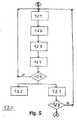
- the in Fig. 3 and 5 The sequence shown represents an empirical mode decomposition (EMD), by means of which the piezoelectrically detected sensor signals are preprocessed, in order finally to obtain one or more suitable IMFs which are particularly suitable for material processing. Characteristics of the examined card characteristic are.
- the performed EMD corresponds to an iterative screening process or smoothing process by which, locally considered, the highest frequency components are obtained in each step. This allows higher-frequency superpositions to be eliminated or amplitudes effectively smoothed. With the help of the EMD characteristic features are obtained in a multi-dimensional feature space, which allow an effective and reliable classification.
- the data of the IMFs obtained in the step sequence 120 can be subjected to further method steps, including a classification, which finally makes an informed decision as to whether a manipulated card or even a foreign body has been introduced into the card reader or not.
- a classification unit KFE For classification, a classification unit KFE (s. Fig. 7 ), which uses a learned classifier KF to treat the data DAT (here the characteristic data of the respective IMF) as test data PDAT and subject it to a pattern order MZ.
- the classifier KF is not static, but is learned or optimized by means of a learning unit LE. This is done by treating the data DAT as training data TDAT and subjecting it to a pattern order MZ.
- the optimized classification KF is then applied to the classification of the real measurement data (test data PDAT).
- the classifier is conditioned as a fuzzy pattern classifier FPK, thus allowing a fuzzy pattern classification.
- a classification describes the problem-adapted evaluation and assignment of data in the context of gradual affiliations (membership functions ⁇ (x)), which are coupled together in a measured orientation (aggregation).
- membership functions can be created by measurements.
- the fuzzy pattern classification is based on the uncertainty of the classes formed from individual observations and uses the concept of the membership function.
- the membership function ⁇ KL: X ⁇ [0,1] assigns to each object x of the feature set X a number from the real-valued interval [0, 1] which indicates the degree of membership ⁇ KL (x) of the object for the so-defined fuzzy set (class) KL ,
- the extracted features include, for example, standard deviation; Skewness, kurtosis, mean absolute deviation from the median; Median of the absolute deviation.
- the Standard deviation is a measure of the dispersion of the values of a random variable around its expected value.
- the skewness is a statistical index that describes the nature and strength of the asymmetry of a probability distribution. It indicates if and how strongly the distribution is inclined to the right (positive skewness) or to the left (negative skewness).
- the kurtosis is a measure of the steepness or "sharpness" of a (one-off) probability function, statistical density function or frequency distribution.
- the vault is the central 4th order moment. Low vault distributions scatter relatively uniformly; for high-vault distributions, the scattering results more from extreme but rare events.
- the median or central value is an average for distributions in the statistics.
- the median of a list of numeric values is the value that is in the middle position when sorting the values by size.
- the median absolute deviation from the median is the spread around the median.
- Scattering also dispersion or mean absolute deviation
- the different calculation methods differ in principle by their influenceability or sensitivity to outliers.
- the distribution of the frequency distribution is called standard error.
- the method uses the class description of a specific supervised learning method from structured, blurred example objects, ie. H. objects that have been assigned to a class by a "teacher” or "expert". Both the elemental blur of the objects and the blurring of the classes are expressed by a unified parametric model of a unicodal asymmetric potential function according to Aizerman.
- the PC of the self-service terminal e.g., ATM
- the electronics power the card reader and is also (optionally) logically connected to it.
- the former is used for defined switching on and off of the card reader, the latter for processing any firmware signals of the card reader, such. a retract or a card feeder. If the signal output of the card reader has not yet been implemented in its firmware, alternatively the power consumption of the card reader can be measured and thus draw conclusions about the operating mode (card feed / retract / output / standby) of the reader.
- the insertion area (s. Fig. 1b
- the card 11 leads and centers to the card reader 3. It is equipped with the said opto-electrical sensor system, ie sensor and light barrier strip (s), which completely detect or capture the geometric dimensions of the card.
- the said opto-electrical sensor system ie sensor and light barrier strip (s)
- the evaluation device 4 evaluates the signals of the sensor strip (s) 6A and / or 6B and of the optional sensor 6C.
- the evaluation device 4 can send signals to the PC, which then in turn by a software (eg OSG) the optional surveillance camera 10 is activated and checks the integrity of the card slot.
- OSG software
Landscapes
- Business, Economics & Management (AREA)
- Accounting & Taxation (AREA)
- Engineering & Computer Science (AREA)
- General Physics & Mathematics (AREA)
- Physics & Mathematics (AREA)
- Finance (AREA)
- Theoretical Computer Science (AREA)
- Strategic Management (AREA)
- General Business, Economics & Management (AREA)
- Economics (AREA)
- Development Economics (AREA)
- Microelectronics & Electronic Packaging (AREA)
- Computer Networks & Wireless Communication (AREA)
- Artificial Intelligence (AREA)
- Computer Vision & Pattern Recognition (AREA)
- Control Of Vending Devices And Auxiliary Devices For Vending Devices (AREA)
- Inspection Of Paper Currency And Valuable Securities (AREA)
Abstract
Ausgehend von einer Kartenleseeinrichtung (20) für ein Selbstbedienungsterminal, die einen Aufnahmeraum (13) für eine Karte (11) aufweist, auf der zu lesende Daten gespeichert sind, wobei die das Selbstbedienungsterminal zumindest eine Sensorik (6A, 6B) und eine damit verbundene Auswertevorrichtung (4) aufweist, wird die Kartenleseeinrichtung (20) gegen Manipulationsversuche gesichert, indem die zumindest eine Sensorik in der Kartenleseeinrichtung (20) angeordnet ist und mindestens eine sich linear erstreckende Sensoranordnung (6A, 6B) umfasst, die in dem Aufnahmeraum (13) angeordnet ist, wobei die Auswertevorrichtung (4) mittels der mindestens einen Sensoranordnung (6A, 6B) mindestens eine räumliche Dimension (1, b) der Karte (11) überprüft. Vorzugsweise ist die mindestens Sensoranordnung als eine Sensorleiste (6A, 6B) mit mehreren linear angeordneten Sensorelementen ausgebildet, die sich in Längsrichtung (X) oder Querrichtung (Y) zu der in den Aufnahmeraum (13) eingeführten Karte (11) erstreckt. Dadurch kann effektiv festgestellt werden, ob die eingeschobene Karte einer echten Karte entspricht oder ob eine Manipulation vorliegt, die insbesondere auf das Innere der Kartenleseeinrichtung abzielt.Starting from a card reading device (20) for a self-service terminal, which has a receiving space (13) for a card (11) on which data to be read are stored, wherein the self-service terminal at least one sensor (6A, 6B) and an associated evaluation device (4), the card reading device (20) is secured against tampering by the at least one sensor is arranged in the card reading device (20) and at least one linearly extending sensor assembly (6A, 6B) arranged in the receiving space (13) wherein the evaluation device (4) checks at least one spatial dimension (1, b) of the card (11) by means of the at least one sensor arrangement (6A, 6B). Preferably, the at least sensor arrangement is designed as a sensor strip (6A, 6B) with a plurality of linearly arranged sensor elements which extend in the longitudinal direction (X) or transverse direction (Y) to the card (11) inserted into the receiving space (13). As a result, it can be effectively determined whether the inserted card corresponds to a real card or whether there is a manipulation which is aimed in particular at the interior of the card reading device.
Description
Die Erfindung betrifft eine Kartenleseeinrichtung für ein Selbstbedienungsterminal, insbesondere für einen Geldautomaten, gemäß dem Oberbegriff des Anspruchs 1. Des Weiteren betrifft die Erfindung ein damit ausgestattetes Selbstbedienungsterminal sowie ein Verfahren zur Überwachung desselben gemäß dem Oberbegriff der nebengeordneten Ansprüche.The invention relates to a card reading device for a self-service terminal, in particular for an ATM, according to the preamble of
Bei Selbstbedienungsterminals, auch kurz SB-Terminals genannt, sind häufig die darin verbauten Kartenleseeinrichtungen ein vorrangiges Ziel für Manipulationsversuche und Skimmingangriffe. Denn zur Bedienung von SB-Terminals, insbesondere von Geldautomaten, benötigt der Nutzer bzw. Kunde eine Bankkarte, die üblicherweise einen Chip sowie einen Magnetstreifen aufweist, auf denen Kartendaten einschließlich der persönlichen Kunden- und Kontozugriffsdaten gespeichert sind. Leider werden an SB-Terminals in zunehmendem Maße Manipulationen durch Dritte vorgenommen, um auf betrügerische Weise an diese Kartendaten zu gelangen. Hierzu wird u.a. versucht, in den Kartenschlitz der Kartenleseeinrichtung möglichst unauffällig eine spezielle Ausspähvorrichtung einzuführen, die geeignet ist, den Magnetstreifen direkt auszulesen oder sich an eine interne / geräteeigene Datenschnittstelle (z.B. USB-Schnittstelle) der Kartenleseeinrichtung anzudocken. Damit sollen letztendlich die Kartendaten ausgelesen werden, um eine illegale Kopie der Bankkarte anfertigen zu können. Des Weiteren sind Skimmingversuche bekannt, bei denen vor dem Kartenschlitz ein fremder Kartenleser als möglichst unauffälliger Überbau angebracht ist, der z.B. per Funk die ausgelesenen Kartendaten an den Betrüger weiterleitet. Wenn es dem Betrüger darüber hinaus gelingt, die zur Bankkarte gehörige Geheimzahl (die sogenannte PIN) auszuspähen, kann er mit der gefälschten Bankkarte und der ausgespähten PIN mühelos an Geldautomaten Geld von dem zugehörigen Konto abheben. Es gibt sogar Skimmingangriffe, welche versuchen, direkt über die interne Schnittstelle einen Kartelesevorgang zu simulieren und die Softwaresteuerung des SB-Terminals bzw. Geldautomaten zu manipulieren.Self-service terminals, also known as self-service terminals for short, often use the card readers installed in them as a primary target for manipulation attempts and skimming attacks. For the operation of self-service terminals, in particular of ATMs, the user or customer requires a bank card, which usually has a chip and a magnetic strip on which card data including the personal customer and account access data are stored. Unfortunately, self-service terminals are increasingly being manipulated by third parties to fraudulently access these map data. For this purpose, an attempt is made inter alia to insert into the card slot of the card reading device as unobtrusively as possible a special spying device which is suitable for directly reading out the magnetic stripe or for docking to an internal / device-specific data interface (eg USB interface) of the card reading device. This should ultimately be read out the map data to make an illegal copy of the bank card can. Furthermore, skimming tests are known in which a foreign card reader is installed in front of the card slot as an inconspicuous superstructure, which, for example, forwards the read-out card data to the fraudster by radio. Moreover, if the fraudster manages to spy on the PIN belonging to the bank card, he can with the fake bank card and the spied pin effortlessly withdraw money from the associated account at ATMs. There are even skimming attacks, which try to simulate a Kartelesevorgang directly via the internal interface and to manipulate the software control of the self-service terminals or ATMs.
Darüber hinaus ist das Ergattern der Geldkarte (Card Trapping) ein bekanntes Angriffszenario. Beim card trapping wird ein Vorbau zum Stehlen der Karte vor den Kartenleser montiert. Dieser Vorbau ist zum Kartenleser hin mit einer Schlaufe versehen, direkt hinter dem Kartenschlitz des Vorbaus ist zudem eine Klappe, die nur eine unidirektionales Einführen der Karte ermöglicht. Wenn ein Kunde seine Karte einführt, wird selbige durch die Schlaufe erfasst und gefangen; die Klappe verhindert einen Auswurf der Karte. Dem Gerätenutzer wird durch das Verhalten des Gerätes ein Einzug der Karte vermittelt. Er verlässt das Selbstbedienungsgerät. Folgend entnimmt der Dieb die Karte einschließlich Vorbau.In addition, getting hold of the card (card trapping) is a well-known attack scenario. When card trapping a stem to steal the card in front of the card reader is mounted. This stem is provided to the card reader with a loop, directly behind the card slot of the stem is also a flap that allows only a unidirectional insertion of the card. When a customer inserts his card, it is caught and caught by the loop; the flap prevents ejection of the card. The device user is taught by the behavior of the device, a withdrawal of the card. He leaves the self-service device. Subsequently the thief removes the card including the stem.
Um Card Trapping zu detektieren, wird nach dem Stand der Technik der Ablauf beim Karteneinzug verändert. Die Karte wird eingezogen, dann erst noch einmal wieder herausgefahren und erst folgend abschließend wieder vom Kartenleser eingezogen. Ist dieser Ablauf nicht einwandfrei möglich, d.h. das Ausgeben der Karte funktioniert nicht, ist davon auszugehen, dass es sich hierbei um den Versuch des Erlangens der Geldkarte handelt. Diese Sicherheitsroutine erhöht die Transaktionszeit am Gerät.In order to detect card trapping, according to the state of the art, the procedure for changing the card is changed. The card is withdrawn, then driven out only once again and finally retracted again by the card reader. If this procedure is not perfectly possible, i. the issuing of the card does not work, it can be assumed that this is an attempt to obtain the cash card. This security routine increases the transaction time on the device.
Auch ist allgemein bekannt, Manipulationsversuchen an SB-Terminals durch den Einsatz von Sensorik entgegenzuwirken. So offenbart die
In der
In diesem Zusammenhang kann auch die
In der
Des Weiteren ist bei Vorrichtungen, die zur Aufbewahrung von Geldmitteln oder Wertgegenständen dienen, insbesondere bei Tresoren oder Banksafes, bekannt, diese vor Fremdeingriffe durch Einsatz von Sensorik zu schützen. So wird z.B. in der
Demnach sind die herkömmlichen Selbstbedienungsterminals mit einer Kartenleseeinrichtung ausgestattet, in die eine Karte einführbar ist, auf welcher zu lesende Daten gespeichert sind, wobei zur Abwehr von Manipulationsversuchen das Selbstbedienungsterminal an sich mit mindestens einer Sensorik und einer damit verbundenen Auswertevorrichtung ausgestattet sein kann. Diese Lösungen sind jedoch nicht zur effektiven Abwehr von Manipulationsversuchen geeignet, die auf das Innere der Kartenleseeinrichtung abzielen.Accordingly, the conventional self-service terminals are equipped with a card reading device into which a card can be inserted, on which data to be read are stored, to defend against manipulation attempts the self-service terminal itself at least one sensor and an associated evaluation device can be equipped. However, these solutions are not suitable for effective defense against manipulation attempts, which are aimed at the interior of the card reading device.
Daher ist es Aufgabe der vorliegenden Erfindung eine Kartenleseeinrichtung der eingangs genannten Art weiterzuentwickeln, so dass auch Manipulationsversuche und Skimmingangriffe, die auf das Innere der Kartenleseeinrichtung abzielen, sicher abgewehrt oder zumindest effektiv erschwert werden. Auch sollen ein Selbstbedienungsterminal, das mit einer solchen Kartenleseeinrichtung ausgestattet ist, sowie ein Verfahren zur Überwachung eines solchen Selbstbedienungsterminals vorgestellt werden.It is therefore an object of the present invention to develop a card reading device of the type mentioned, so that manipulation attempts and skimming attacks, which are aimed at the interior of the card reading device, safely fended off or at least effectively hampered. Also, a self-service terminal equipped with such a card reading device and a method for monitoring such a self-service terminal will be presented.
Gelöst wird die Aufgabe durch eine Kartenleseeinrichtung mit den Merkmalen des Anspruchs 1 sowie durch ein Selbstbedienungsterminal und ein Verfahren mit den Merkmalen des entsprechend nebengeordneten Anspruchs.The object is achieved by a card reading device having the features of
Demnach wird eine Kartenleseeinrichtung vorgestellt, bei der die zumindest eine Sensorik in der Kartenleseeinrichtung angeordnet ist und mindestens eine sich linear erstreckende Sensoranordnung umfasst, wobei die Auswertevorrichtung mittels der mindestens einen Sensoranordnung mindestens eine räumliche Dimension der Karte überprüft. Es wird also eine Kartenleseeinrichtung vorgestellt, bei der die zumindest eine Sensorik in der Kartenleseeinrichtung selbst angeordnet ist und vorzugsweise in oder an einem Aufnahmeraum für die zu lesende Karten angeordnet ist, wobei die Auswertevorrichtung mittels der mindestens einen Sensoranordnung mindestens eine räumliche Dimension der Karte, insbesondere deren Breite und/oder Länge, überprüft. Als Sensoranaordnungen können beispielsweise opto-elektrische Sensorleisten verwendet werden.Accordingly, a card reading device is presented in which the at least one sensor system is arranged in the card reading device and comprises at least one linearly extending sensor arrangement, wherein the evaluation device checks at least one spatial dimension of the card by means of the at least one sensor arrangement. Thus, a card reading device is presented in which the at least one sensor is arranged in the card reading device itself and is preferably arranged in or on a receiving space for the cards to be read, wherein the evaluation device by means of at least one sensor arrangement at least one spatial dimension of the card, in particular whose width and / or length, checked. As sensor arrangements, for example, opto-electrical sensor strips can be used.
Die Erfindung stellt auch ein Selbstbedienungsterminal, insbesondere einen Geldautomat, mit einer solchen Kartenleseeinrichtung bereit. Außerdem wird hier ein Verfahren vorgestellt, mit dem eine Überwachung des Selbstbedienungsterminals bzw. Geldautomaten mittels der Sensorik und der Auswertevorrichtung durchgeführt wird, wobei die Sensorik in der Kartenleseeinrichtung angeordnet ist und mindestens eine sich linear erstreckende Sensoranordnung umfasst, die vorzugsweise in dem Aufnahmeraum angeordnet ist, und wobei mittels der Auswertevorrichtung und der mindestens einen Sensoranordnung zumindest eine räumliche Dimension der Karte überprüft wird.The invention also provides a self-service terminal, in particular an ATM, with such a card reading device. In addition, a method is presented here, with which a monitoring of the self-service terminal or ATM is performed by means of the sensor and the evaluation device, wherein the sensor is arranged in the card reading device and at least one linearly extending Sensor arrangement comprises, which is preferably arranged in the receiving space, and wherein at least one spatial dimension of the card is checked by means of the evaluation device and the at least one sensor arrangement.
Demzufolge wird im Innern der Kartenleseeinrichtung eine Sensorik installiert, um das dort befindliche eingeführte Objekt auf die räumlichen Dimensionen einer normalen Karte hin zu überprüfen, so dass sehr effektiv erkannt werden kann, ob sich in der Kartenleseeinrichtung tatsächlich eine normale Karte befindet oder etwa ein Fremdobjekt, wie z.B. eine Kartenähnlich-dimensionierte Ausspähvorrichtung.Consequently, a sensor system is installed in the interior of the card reading device in order to check the inserted object located there in the spatial dimensions of a normal card, so that it can be very effectively recognized whether a normal card is actually present in the card reading device or a foreign object, for example. such as a card-like sized spying device.
Bevorzugte Ausführungsbeispiele sind den Unteransprüchen zu entnehmen.Preferred embodiments are given in the dependent claims.
Vorzugsweise ist die mindestens eine Sensoranordnung als eine Sensorleiste ausgebildet, die mehrere linear angeordneten Sensorelemente aufweist, wobei die Sensorleiste sich in Längsrichtung oder Querrichtung zu der eingeführten Karte erstreckt. Dabei kann eine erste Sensorleiste die Länge der Karte als erste räumliche Dimension erfassen und/oder eine zweite Sensorleiste die Breite der Karte als zweite räumliche Dimension erfassen.Preferably, the at least one sensor arrangement is formed as a sensor bar, which has a plurality of linearly arranged sensor elements, wherein the sensor bar extends in the longitudinal or transverse direction to the inserted card. In this case, a first sensor strip can detect the length of the card as a first spatial dimension and / or a second sensor strip can detect the width of the card as a second spatial dimension.
Vorzugsweise kann auch nur eine Sensorleiste eingesetzt werden, um Breite und Länge zu erfassen bzw. zu überprüfen. Beispielsweise ist die zweite Sensorleiste so ausgebildet, dass die nicht nur die Breite der Karte erfasst, sondern auch die Länge der Karte erfasst, indem die zweite Sensorleiste beim Einschubvorgang der Karte deren Anfang und Ende erkennt und indem die Auswertevorrichtung mittels einer Zeitmessung und anhand einer vorgegeben Einschubgeschwindigkeit die Länge der Karte ermittelt.Preferably, only one sensor bar can be used to detect and check width and length. For example, the second sensor bar is designed so that not only detects the width of the card, but also detects the length of the card by the second sensor bar detects when inserting the card whose beginning and end and by the evaluation by means of a time measurement and by a given Insertion speed determines the length of the card.
Somit ist die jeweilige in der Kartenleseeinrichtung installierte Sensoranordnung vorzugsweise als eine Sensorleiste mit mehreren linear angeordneten Sensorelementen ausgebildet, die sich in Längsrichtung oder Querrichtung der in den Aufnahmeraum eingeführten Karte erstreckt. Dabei erfasst vorzugsweise eine erste Sensorleiste die Länge der Karte als erste räumliche Dimension und/oder erfasst eine zweite Sensorleiste die Breite der Karte als zweite räumliche Dimension. Zusätzlich dazu kann in der Kartenleseeinrichtung eine erste zusätzliche Sensorik angeordnet sein, welche die Höhe der Karte als dritte Dimension erfasst. Vorzugsweise sind die Sensorelemente der mindestens einen Sensoranordnung und/oder der ersten zusätzlichen Sensorik als opto-elektrische Sensorelemente ausgebildet. Alternativ können aber auch andere Sensortypen eingesetzt werden, mit denen die räumlichen Karten-Dimensionen erfasst werden können.Thus, the respective sensor arrangement installed in the card reading device is preferably designed as a sensor strip with a plurality of linearly arranged sensor elements which extend in the longitudinal or transverse direction of the card inserted into the receiving space. Preferably, a first sensor strip detects the length of the card as the first spatial dimension and / or detects a second sensor bar, the width of the card as a second spatial dimension. In addition, in the card reading device, a first additional sensor system can be arranged, which detects the height of the card as a third dimension. Preferably, the sensor elements are the at least one Sensor arrangement and / or the first additional sensor as opto-electrical sensor elements formed. Alternatively, however, other sensor types can be used with which the spatial map dimensions can be detected.
Außerdem kann in der Kartenleseeinrichtung eine weitere zusätzliche Sensorik vorgesehen sein, insbesondere opto-elektrische Sensorik, die in Nähe der Oberfläche der Karte angeordnet ist, um Material-Eigenschaften der Karte zu prüfen, insbesondere durch diskrete Spektroskopie.In addition, in the card reading device, a further additional sensor system may be provided, in particular optoelectrical sensor system which is arranged in the vicinity of the surface of the card to check material properties of the card, in particular by discrete spectroscopy.
Auch kann vorgesehen sein, dass auch an einem Einzugs-Bereich, insbesondere Ablagefach (Retract-Fach), für einzuhaltende Karten eine zusätzliche Sensorik, insbesondere Lichtschranke, angeordnet ist, die mit der mindestens einen Auswertevorrichtung verbunden ist und die insbesondere ein oder mehrere opto-elektrische Sensorelemente aufweist, um Manipulationen an dem Einzugs-Bereich zu erfassen. Die Kartenleseeinrichtung kann also in einer bevorzugten Ausführungsform so weiter ausgebildet sein, dass an dem Einzugs-Bereich (sog. Retract-Bereich) für einzuhaltende Karten eine weitere zusätzliche Sensorik angeordnet ist, die mit der mindestens einen Auswertevorrichtung verbunden ist und die insbesondere ein oder mehrere Sensorelemente aufweist, um Manipulationen an dem Einzugs-Bereich zu erfassen. Auch diese Sensorelemente sind vorzugsweise opto-elektrische Bauelemente für eine Lichtschranke, können aber auch aber auch andere Bauelemente bzw. Sensortypen sein, mit der Bereich überwacht werden kann.It can also be provided that an additional sensor system, in particular a light barrier, is arranged on a catchment area, in particular a storage compartment (retract compartment), which is connected to the at least one evaluation device and which in particular has one or more optoelectronic sensors. having electrical sensor elements to detect tampering with the feeder area. In a preferred embodiment, the card reading device can thus be configured further such that a further additional sensor system, which is connected to the at least one evaluation device and in particular one or more, is arranged at the catchment area (so-called retract area) for cards to be kept Sensor elements to detect tampering with the feeder area. These sensor elements are also preferably opto-electrical components for a light barrier, but may also be other components or sensor types with which the area can be monitored.
Die Kartenleseeinrichtung, die üblicherweise ein Gehäuse und/oder einen Aufnahmeraum aufweist, in das/den die Karte einziehbar ist, kann so ausgebildet sein, dass die mindestens eine Auswertevorrichtung mit mechatronischen Wandlern, insbesondere Piezo-elektrischen Wandlern, umfassend Sensoren und/oder Aktoren verbunden ist, wobei die mechatronischen Wandler so in oder an dem Gehäuse und/oder Aufnahmeraum angeordnet sind, dass die Integrität der Kartenleseeinrichtung, insbesondere des Gehäuses und/oder Aufnahmeraums, prüfbar ist, wobei die Auswertevorrichtung eingerichtet ist, um von den mechatronischen Wandlern ein Signal zu empfangen, das von einem Teil der mechatronischen Wandler angeregt ist und von einem Teil der mechatronischen Wandler detektiert wird, um dieses mit Referenzdaten zu vergleichen, und um bei einer definierten Abweichung ein Warnsignal auszugeben, das für eine fehlende Integrität der Kartenleseeinrichtung steht. Es können also in oder an dem Aufnahmeraum der Kartenleseeinrichtung mechatronische Wandler vorgesehen sein, insbesondere Piezo-elektrische Wandler, umfassend Sensoren und/oder Aktoren, die mit einer Auswertevorrichtung verbunden sind. Diese Wandler sollen dazu dienen, eine Schwingung, vorzugsweise im hörbaren Schallbereich bzw. Eigenfrequenzbereich, auf die Kartenleseeinrichtung auszuüben, um die Integrität der Kartenleseeinrichtung, insbesondere des Gehäuses und/oder Aufnahmeraums, zu überprüfen. Dazu verwaltet die Auswertevorrichtung z.B. Referenzdaten von den mechatronischen Wandlern, die einen zulässigen Zustand des Aufnahmeraums repräsentieren. Die mechatronischen Wandler können auch in einem Sensorfeld (patch) angeordnet sein, Dabei umfasst das Sensorfeld vorzugsweise mehrere schall-elektrische, insbesondere mehrere piezo-elektrische Sensorelemente. Ein solches Sensorfeld könnte auch in oder an dem Aufnahmeraum der Kartenleseeinrichtung befestigt werden, vorzugsweise parallel zu einer Oberfläche der Karte, um auch auf diesem Weg die Material-Eigenschaften der Karte zu prüfen. Dabei können einzelene Elemente des Sensorfeldes als Aktoren, insbesondere piezo-elektrische Aktoren, fungieren, die den Bereich der Kartenleseeinrichtung zum Schwingen angeregen, so dass von den anderen Sensorelementen des Sensorfeldes die auszuwertenden Signale erzeugt werden. Demnach könnte die Auswertevorrichtung so erweitert werden, dass sie nicht nur die Signale von den opto-elektrischen Sensorleisten auswerte, sondern auch die Signale die von anderen Sensorelementen, insbesondere von den Sensorelementen des mechatronischen Sensorfeldes, kommen.The card reading device, which usually has a housing and / or a receiving space into which the card is retractable, can be configured such that the at least one evaluation device is connected to mechatronic transducers, in particular piezoelectric transducers, comprising sensors and / or actuators is, wherein the mechatronic transducers are arranged in or on the housing and / or receiving space, that the integrity of the card reading device, in particular of the housing and / or receiving space is testable, wherein the evaluation device is adapted to receive a signal from the mechatronic transducers which is excited by a part of the mechatronic transducers and is detected by a part of the mechatronic transducers in order to compare this with reference data, and to output at a defined deviation a warning signal which represents a lack of integrity of the card reading device. So it can be in or mechatronic transducers may be provided at the receiving space of the card reading device, in particular piezoelectric electrical transducers, comprising sensors and / or actuators, which are connected to an evaluation device. These transducers are intended to exert a vibration, preferably in the audible sound range or natural frequency range, on the card reading device in order to check the integrity of the card reading device, in particular of the housing and / or receiving space. For this purpose, the evaluation device manages eg reference data from the mechatronic transducers, which represent a permissible state of the recording space. The mechatronic transducers can also be arranged in a sensor field (patch). In this case, the sensor field preferably comprises a plurality of sound-electric, in particular a plurality of piezoelectric electrical sensor elements. Such a sensor field could also be fixed in or on the receiving space of the card reading device, preferably parallel to a surface of the card, in order also to check the material properties of the card in this way. In this case, individual elements of the sensor field act as actuators, in particular piezoelectric actuators, which stimulate the region of the card reading device to vibrate, so that the signals to be evaluated are generated by the other sensor elements of the sensor field. Accordingly, the evaluation could be extended so that they not only evaluate the signals from the opto-electrical sensor strips, but also the signals coming from other sensor elements, in particular from the sensor elements of the mechatronic sensor array.
Nachfolgend wird die Erfindung im Detail anhand von Ausführungsbeispielen und unter Bezugnahme auf die beiliegenden Zeichnungen beschrieben, die folgende schematische Darstellungen wiedergeben:
- Fig. 1a
- zeigt den Aufbau der Kartenleseeinrichtung in einer Querschnittansicht
- Fig. 1b
- ;zeigt in einer dreidimensionalen Ansicht den Aufbau einer Kartenleseeinrichtung zum Einbau in ein Selbstbedienungsterminal;
- Fig. 2
- zeigt in einer schematischen Darstellung die Anordnung von Sensorleisten zum Prüfen der Dimensionen (Länge, Breite, Höhe) einer Karte;
- Fig. 3, 5
- zeigen Diagramme für eine Signal-Vorverarbeitung, die als Schrittfolge innerhalb des Verfahrens durchgeführt wird;
- Fig. 4a-c
- veranschaulichen die logischen Zusammenhänge zwischen den durchgeführten Verfahrensschritten; a= Karteneinschub, b=Retract c=Prüfung der Hüllenintegrität
- Fig. 6a&b
- veranschaulichen die mittels des Verfahrens durchgeführte Merkmalsextraktion und Klassifikation;
- Fig. 7
- ist eine schematische Darstellung, die die Funktion eines für die Klassifikation verwendeten lernfähigen Klassifikators veranschaulicht;
- Fig. 8
- veranschaulicht die Funktion eines Fuzzy-Pattern-Klassifikators; und
- Fig. 9
- stellt den Ablauf eines beispielhaft ausgeführten Verfahrens dar.
- Fig. 1a
- shows the construction of the card reading device in a cross-sectional view
- Fig. 1b
- 3 shows in a three-dimensional view the structure of a card reading device for installation in a self-service terminal;
- Fig. 2
- shows a schematic representation of the arrangement of sensor strips for checking the dimensions (length, width, height) of a map;
- Fig. 3, 5
- show diagrams for signal preprocessing performed as a step sequence within the method;
- Fig. 4a-c
- illustrate the logical relationships between the process steps performed; a = card insert, b = retract c = check the envelope integrity
- 6a & b
- illustrate the feature extraction and classification performed by the method;
- Fig. 7
- Fig. 12 is a schematic diagram illustrating the function of an adaptive classifier used for the classification;
- Fig. 8
- illustrates the function of a fuzzy pattern classifier; and
- Fig. 9
- illustrates the flow of an exemplary process performed.
In den
Unter dem Begriff Kartenleseeinrichtung wird hier die Gesamtanordnung (s.
Einzige Öffnungen des Gehäuses sind die Öffnung für Karteneinschub (IDKG-Einsatz 5) und der damit verbundenen Detektion durch die additiven Sensoren 6 sowie der Durchbruch für eingezogene Karten, welche durch eine Lichtschranke7 überwacht wird.The only openings of the housing are the opening for card insertion (IDKG insert 5) and the associated detection by the
Wie insbesondere die
Die Kartenleseeinrichtung 20 ist mit der in
Die Sensorik ist so ausgebildet, dass zumindest eine Dimension erfasst werden kann, vorzugsweise Breite b und Länge l, optional noch die Höhe der Karte. Der Sensor 6B misst insbesondere die Breite b der Karte. Dieser kann auch für die Messung der Karten-Länge l verwendet werden, z.B. durch eine zeitgetriggerte Erfassung an dem Sensor 6B, wobei anhand der Einzugsgeschwindigkeit / -dauer die Karten-Länge l ermittelt. Es können auch für jede Dimension einzelne Sensoren verwendet werden. Insbesondere können Sensorleisten eingesetzt werden, wie z.B. opto-elektrische Sensorleisten vom Typ TSL208R, die von der Firma TAOS hergestellt werden und 512 Photodioden in einem Abstand von 125 µm aufweisen. Somit kann eine sehr genaue Messung durchgeführt werden. Des Weiteren kann noch eine zusätzliche Sensorik 6C an dem Kartenleser bzw. dem Aufnahmeraum 13 angeordnet sein, um auch die Höhe der Karte (in Z-Richtung) zu messen bzw. zu überprüfen. Je nach Anwendungsfall kann es aber ausreichen, nur eine oder zwei Dimensionen, vorzugsweise Länge und/oder Breite, zu messen.The sensor system is designed so that at least one dimension can be detected, preferably width b and length l, optionally also the height of the card. In particular, the
Durch die installierten Sensoriken 6A, 6B, 6C und/oder 6D (optional) sowie mit der Lichtschranke 7 in Verbindung mit dem Signal zum Retract vom Kartenleser 3 können die Durchbrüche des Gehäuses gesichert werden. Zusätzlich kann hierfür auch noch eine optional installierte Kamera 10 (s.
Zunächst wird auf die
- A1: Die opto-elektrischen Sensorelemente erzeugen Messsignale für die Breite b, die Länge l und optional für die Höhe der
Karte 11. - A2: Die Auswertevorrichtung bzw. -
elektronik 4 prüft die Messdaten bzw. Messwerte, indem sie diese im Wesentlichen mit Standardwerten für genormte Bankkarten bzw. Geldkartenvergleicht. - A3: Wenn die Messdaten den Standardwerten entsprechen, handelt es sich um eine normale Geldkarte.
- A4: Eine Anregen mittels des piezo-
elektrischen Sensorfeldes 6D wird vorzugsweise nicht während des Betriebs des Kartenlesers durchgeführt. - A5: Jedoch wird eine Überwachung von Kartenleserdaten durchgeführt, insbesondere von den Kartenlesersignalen und/oder der Stromaufnahme des Kartenlesers.
- A6. Sofern im Block A2 festgestellt wurde, dass die Messdaten von den Standardwerten abweichen, handelt es sich um keine normale Geldkarte und es wird angenommen, dass ein Manipulationsversuch vorliegt.
- A7: Der Kartenleser wird abgeschaltet; wenn möglich wird die manipulierte Karte bzw. Kartenattrappe eingezogen.
- A8: Die Softwaresteuerung des SB-Terminals, hier ein PC, erhält ein Warnsignal.
- A9: Ein Anregen zu definierten Betriebszeitpunkten zur Feststellung der Integrität der Hülle kann durchgeführt werden
- A10: Eine optionale Kameraüberwachung (s. 10 in
Fig. 1a ) kann Signale (Bild, Video, und/oder Audio) erzeugen. - A11: Die Kamera-Signale werden an die Auswertevorrichtung19 bzw. den PC gesendet, um den Manipulationsversuch besser zu dokumentieren und ggf. Bilder von verdächtigen Personen zwecks späterer Identifizierung aufzunehmen.
- A12: ist optional und zeigt an, dass Block A9 ausgeführt wird, sofern Kartenleserdaten und -signale es zulassen.
- A1: The opto-electrical sensor elements generate measurement signals for the width b, the length l and optionally for the height of the
card 11. - A2: The evaluation device or
electronics 4 checks the measurement data or measured values by comparing them substantially with standard values for standardized bank cards or cash cards. - A3: If the measurement data matches the default values, it is a normal cash card.
- A4: An excitation by means of the piezo-
electric sensor array 6D is preferably not carried out during the operation of the card reader. - A5: However, monitoring of card reader data is performed, in particular of the card reader signals and / or the power consumption of the card reader.
- A6. If it has been determined in block A2 that the measured data deviate from the standard values, this is not a normal cash card and it is assumed that a manipulation attempt has been made.
- A7: The card reader is turned off; if possible, the manipulated card or dummy will be confiscated.
- A8: The software control of the self-service terminal, here a PC, receives a warning signal.
- A9: Excitation at defined operating times to establish the integrity of the envelope can be performed
- A10: An optional camera surveillance (see 10 in
Fig. 1a ) can generate signals (image, video, and / or audio). - A11: The camera signals are sent to the Auswertevorrichtung19 or the PC to better document the manipulation attempt and possibly take pictures of suspected persons for later identification.
- A12: is optional and indicates that block A9 will be executed if card reader data and signals allow it.
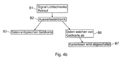
Die
- B1: Die opto-elektrische Sensorik bzw.
Lichtschranke 7 am Retract-Schacht erzeugt Signale,wenn eine Karte 11 oder Attrappe bzw. ein Fremdgegenstand durch den Schacht befördert wird oder wenn von hinten durchdas Fach 8 ein Fremdgegenstand inden Kartenleser 3 eingeführt werden soll. - B2: Die Auswerteelektronik gleicht das Ereignis mit dem Status des Kartenlesers ab, d.h. liegt ein retract vor, ist das Ereignis als in Ordnung einzustufen. Alle anderen Ereignisse werden als Manipulation bewertet
- B3: Anhand der Signale bzw. Messwerte wird festgestellt, dass eine normale Geldkarte durch den Retract-
Schacht 7 geführt wird bzw. dass ein normaler Retract-Vorgang stattfindet. - B6: Sofern im Block B2 festgestellt wurde, dass keine normale Geldkarte durch den Retract-
Schacht 7 geführt wurde bzw. dass kein normaler Retract-Vorgang erfolgte, wird ein Manipulationsversuch angenommen. - B7: Der Kartenleser wird abgeschaltet.
- B1: The opto-electrical sensor or
light barrier 7 at the retracting shaft generates signals when acard 11 or dummy or a foreign object is conveyed through the shaft or when a foreign object is to be inserted into thecard reader 3 from behind through thecompartment 8 , - B2: The transmitter matches the event with the status of the card reader, ie if there is a retract, the event is considered to be in order. All other events are considered manipulation
- B3: Based on the signals or measured values, it is determined that a normal money card is passed through the retracting
shaft 7 or that a normal retracting process takes place. - B6: If it has been determined in block B2 that no normal money card has been passed through the retract
shaft 7 or that no normal retract procedure has taken place, a manipulation attempt is assumed. - B7: The card reader is turned off.
Die
- CI:
Die Auswertevorrichtung 4 veranlasst eine Überprüfung des Gehäuses, indem piezo-elektrische Aktoren, die am Gehäuse montiert sind, zum Schwingen anregt werden, und indem Messdaten von dort montierten piezo-elektrischen Sensorfelder ausgewertet werden. Die Aktoren können in den Sensorfeldern (vergleichbar mit 6D inFig. 1b ) integriert sein bzw. einzelne Piezo-Elemente des jeweiligen Feldes sein, welche zur Schwingungsanregung angesteuert werden. - CII: Zuerst werden die piezo-elektrischen Aktoren mit bestimmten Frequenzen bzw. mittels Sweep angeregt.
- CIII: Die Sensoren erfassen Signalmuster.
- CIV: Die Auswertevorrichtung wertet gemäß dem hier beschriebenen Verfahren aus.
- CV: Die Integrität des Gehäuses ist vorhanden, dann beginnt der Zyklus von vorn bei CI.
- CVI: Die Integrität des Gehäuses ist nicht vorhanden, dann wird der Leser abgeschaltet.
- CVII: Der Kartenleser wird abgeschaltet; ggf. sogar das ganze SB-Terminal.
- CI: The
evaluation device 4 causes a review of the housing by piezoelectric actuators mounted on the housing, are excited to vibrate, and by measuring data from there mounted piezo-electric sensor arrays are evaluated. The actuators can be used in the sensor fields (comparable to 6D inFig. 1b ) be integrated or be individual piezoelectric elements of the respective field, which are driven to vibrate excitation. - CII: First, the piezoelectric actuators are excited at certain frequencies or sweep.
- CIII: The sensors detect signal patterns.
- CIV: The evaluation device evaluates according to the procedure described here.
- CV: The integrity of the case is there, then the cycle starts over at CI.
- CVI: The integrity of the enclosure is absent, then the reader is turned off.
- CVII: The card reader is switched off; possibly even the whole self-service terminal.
Die Überprüfung des Gehäuses kann auch Teil des hier offenbarten Verfahrens sein, kann aber auch als eigenständige Lösung ausgeführt werden. Bei dierser eigenständigen Lösung handelt es sich darum, dass in oder an der Kartenleseeinrichtung mechatronische Wandler installiert sind, insbesondere Piezo-elektrische Wandler, umfassend Sensoren und/oder Aktoren, die mit einer Auswertevorrichtung verbunden sind. Diese Wandler sollen dazu dienen, eine Schwingung, vorzugsweise im hörbaren Schallbereich bzw. Eigenfrequenzbereich, auf die Kartenleseeinrichtung, insbesondere dessen Gehäuse auszuüben. Die mechatronischen Wandler sind dabei so in, um oder an der Kartenleseeinrichtung bzw. dem Gehäuse angeordnet sind, dass die Integrität der Kartenleseeinrichtung, insbesondere des Gehäuses, prüfbar ist, wobei die Auswertevorrichtung eingerichtet ist, um von den mechatronischen Wandlern ein Signal zu empfangen, das von einem Teil der mechatronischen Wandler angeregt ist und von einem Teil der mechatronischen Wandler detektiert wird, um dieses mit Referenzdaten zu vergleichen, und um bei einer definierten Abweichung ein Warnsignal auszugeben, das für eine fehlende Integrität der Kartenleseeinrichtung steht.The inspection of the housing may also be part of the method disclosed here, but may also be carried out as a stand-alone solution. In this separate solution is that in or on the card reading mechatronic transducers are installed, in particular piezoelectric converters, comprising sensors and / or actuators, which are connected to an evaluation device. These transducers are intended to exert a vibration, preferably in the audible sound range or natural frequency range, on the card reading device, in particular its housing. In this case, the mechatronic transducers are arranged in or around the card reading device or housing such that the integrity of the card reading device, in particular of the housing, can be tested, wherein the evaluation device is set up to receive a signal from the mechatronic transducers is excited by a part of the mechatronic transducers and is detected by a part of the mechatronic transducers to compare this with reference data, and to output at a defined deviation, a warning signal that stands for a lack of integrity of the card reading device.
Nachfolgend wird die Überprüfung des Karten-Materials mittels des im Kartenleser installierten piezo-elektrischen oder optischen Sensorfeldes 6D (s.
- Zur Überprüfung der Integrität des Gehäuses 1, der Kartenleseeinrichtung, des Karten-Materials und/oder des Aufnahmeraums für die
Karte 11 werden die von dem/den Sensorfeld(ern) 6D kommenden Messsignale inder Auswertevorrichtung 4 zunächst einer Signalvorbereitung unterzogen. Dies geschieht in der Schrittfolge mit den Schritten 121-128 und wird anhand derFiguren 3 und5 näher beschrieben:- Für das jeweils erfasste Eingangssignal (Anfangs- bzw. Einstiegspunkt E) werden zuerst in einem
Schritt 121 die lokalen Extrema bestimmt, d.h. die im zeitlichen Signalverlauf auftretenden absoluten sowie relativen Maxima und Minima der Amplitude. Dann wird ineinem Schritt 122 eine obere und untere Einhüllende konstruiert, d.h. eine obere Kurve, welche die Maxima verbindet und eine untere Kurve, welche die Minima verbindet. Dann wird ineinem Schritt 123 der Mittelwert der Einhüllenden gebildet, vorzugsweise der arithmetische (oder ein alternativer) Mittelwert. In einem weiterenSchritt 124 erfolgt dann eine Extraktion einer möglichen intrinsischen Modalfunktion (auch kurz "IMF" genannt). Die Schritte 121-124 werden in Iterationen durchgeführt, wobeidann im Schritt 125 geprüft wird, ob und wie stark der Unterschied zweier aufeinanderfolgender Iterationsschritte ist, d.h. ob und wie stark die beiden IMFs voneinander abweichen.
- Für das jeweils erfasste Eingangssignal (Anfangs- bzw. Einstiegspunkt E) werden zuerst in einem
- To check the integrity of the
housing 1, the card reading device, the card material and / or the receiving space for thecard 11, the measurement signals coming from the sensor field (s) 6D in theevaluation device 4 are first subjected to signal preparation. This is done in the step sequence with steps 121-128 and is based on theFigures 3 and5 described in more detail:- For the respectively detected input signal (starting point or entry point E), the local extrema are first determined in a
step 121, ie the absolute and relative maxima and minima of the amplitude occurring in the temporal signal course. Then, in astep 122, an upper and lower envelope is constructed, ie, an upper curve connecting the maxima and a lower curve connecting the minima. Then, instep 123, the mean of the envelope is formed, preferably the arithmetic (or an alternative) mean. In afurther step 124, an extraction of a possible intrinsic modal function (also called "IMF" for short) then takes place. The steps 121-124 are performed in iterations, and then it is checked instep 125 whether and how much the difference between two successive iteration steps is, ie whether and how much the two IMFs differ from each other.
- For the respectively detected input signal (starting point or entry point E), the local extrema are first determined in a
Ist der Unterschied größer als ein vorgebbares Maß, so wird die nächste Iteration durchgeführt (Schritte 121-124). Andernfalls kann die (zuletzt) ermittelte IMF verwendet werden (Schritt 126). Außerdem wird dann im Schritt 127 das Residuum extrahiert und anschließend im Schritt 128 mit einem Schwellenwert verglichen. Ist das Residuum größer als der Schwellenwert, so wird die nächste Iteration durchgeführt (Schritte 121-124). Andernfalls kann der Vorgang abgebrochen werden (Endpunkt A = "Abbruch"). In diesem Fall wird die im Schritt 126 als geeignet befundene IMF weiterverwendet.If the difference is greater than a predeterminable amount, the next iteration is performed (steps 121-124). Otherwise, the (last) detected IMF may be used (step 126). In addition, the residue is then extracted in
Der in
Die in der Schrittfolge 120 erhaltenen Daten der IMFs können weiteren Verfahrensschritten unterzogen werden, einschließlich einer Klassifikation, welche schließlich eine fundierte Entscheidung ermöglicht, ob eine manipulierte Karte oder gar ein Fremdkörper in den Kartenleser eingeführt wurde oder nicht.The data of the IMFs obtained in the
Zunächst sei angemerkt, dass bei der Verwendung der durch die IMFs repräsentierten Merkmale grundsätzlich folgendes beachtet wird:
- o Merkmale dienen der Unterscheidung von Zuständen.
- o Merkmale sollten (wie hier) aus den vermuteten Objekteigenschaften abgeleitet werden.
- o Merkmale sollen voneinander unabhängig sein (s. in
Fig. 6b Fälle (i) und (iii)). - o Objekte der gleichen Klasse sollten im Merkmalsraum an ähnlichen Orten zu finden sein (s. Häufungspunkte bzw. Cluster wie in
Fig. 6a veranschaulicht). - o Je weniger Merkmale zur Unterscheidung notwendig sind, desto effektiver wird die Entscheidung sein.
- o Die Generierung guter Merkmale ist auf den jeweiligen Anwendungsfall hin zu konzeptionieren.
- o Characteristics are used to distinguish states.
- o Characteristics should be derived (as here) from the suspected object properties.
- o Characteristics should be independent of each other (see
Fig. 6b Cases (i) and (iii)). - o Objects of the same class should be found in the feature space at similar locations (see cluster points or clusters as in
Fig. 6a illustrated). - o The fewer features needed to differentiate, the more effective the decision will be.
- o The generation of good features is to be designed according to the respective application.
Die gewonnenen IMFs repräsentieren im Wesentlichen einen statistischen Merkmalspool (s. auch
- Zuvor sei erwähnt, dass die aus der Signal-Vorverarbeitung (
Schritt 120 inFig. 5 ) gewonnene IMF optional einer Segmentierung und anschließenden Merkmalsextraktion unterworfen werden kann. Auf diese Verfahrens-Schritte wird aber nicht näher eingegangen, da die Klassifikation hier im Vordergrund steht.
- It should be mentioned previously that the signal preprocessing (
step 120 in FIGFig. 5 ) IMF can optionally be subjected to a segmentation and subsequent feature extraction. However, these procedural steps will not be discussed in more detail, since the classification is in the foreground here.
Zur Klassifikation wird eine Klassifikationseinheit KFE (s.
Wie die
Als Eingabe für die in
Die extrahierten Merkmale umfassen z.B. Standarabweichung; Schiefe, Kurtosis, mittlere absolute Abweichung vom Median; Median der absoulten Abweichung. Die Standardabweichung ist ein Maß für die Streuung der Werte einer Zufallsvariablen um ihren Erwartungswert. Die Schiefe ist eine statistische Kennzahl, die die Art und Stärke der Asymmetrie einer Wahrscheinlichkeitsverteilung beschreibt. Sie zeigt an, ob und wie stark die Verteilung nach rechts (positive Schiefe) oder nach links (negative Schiefe) geneigt ist. Die Kurtosis ist eine Maßzahl für die Steilheit bzw. "Spitzigkeit" einer (eingipfligen) Wahrscheinlichkeitsfunktion, statistischen Dichtefunktion oder Häufigkeitsverteilung. Die Wölbung ist das zentrale Moment 4. Ordnung. Verteilungen mit geringer Wölbung streuen relativ gleichmäßig; bei Verteilungen mit hoher Wölbung resultiert die Streuung mehr aus extremen, aber seltenen Ereignissen.The extracted features include, for example, standard deviation; Skewness, kurtosis, mean absolute deviation from the median; Median of the absolute deviation. The Standard deviation is a measure of the dispersion of the values of a random variable around its expected value. The skewness is a statistical index that describes the nature and strength of the asymmetry of a probability distribution. It indicates if and how strongly the distribution is inclined to the right (positive skewness) or to the left (negative skewness). The kurtosis is a measure of the steepness or "sharpness" of a (one-off) probability function, statistical density function or frequency distribution. The vault is the central 4th order moment. Low vault distributions scatter relatively uniformly; for high-vault distributions, the scattering results more from extreme but rare events.
Der Median oder Zentralwert ist ein Mittelwert für Verteilungen in der Statistik. Der Median einer Auflistung von Zahlenwerten ist der Wert, der an der mittleren Stelle steht, wenn man die Werte der Größe nach sortiert. Unter mittlere absolute Abweichung vom Median versteht man die Streuung um den Median. Unter Streuung (auch Dispersion oder mittlere absolute Abweichung) fasst man in der deskriptiven Statistik und in der Stochastik verschiedene Maßzahlen zusammen, die die Streubreite von Werten einer Häufigkeitsverteilung oder Wahrscheinlichkeitsverteilung um einen geeigneten Lageparameter herum beschreiben. Die verschiedenen Berechnungs-methoden unterscheiden sich prinzipiell durch ihre Beeinflussbarkeit beziehungsweise Empfindlichkeit gegenüber Ausreißern. Die Streuung der Häufigkeitsverteilung wird als Standardfehler bezeichnet.The median or central value is an average for distributions in the statistics. The median of a list of numeric values is the value that is in the middle position when sorting the values by size. The median absolute deviation from the median is the spread around the median. Scattering (also dispersion or mean absolute deviation) in descriptive statistics and in stochastics combines different measures describing the range of values of a frequency distribution or probability distribution around a suitable positional parameter. The different calculation methods differ in principle by their influenceability or sensitivity to outliers. The distribution of the frequency distribution is called standard error.
Die Methode bedient sich für die Klassenbeschreibung eines speziellen Verfahrens des überwachten Lernens (supervised learning) aus strukturierten, unscharfen Beispielobjekten, d. h. aus Objekten, denen durch einen "Lehrer" oder "Experten" ein Zugehören zu einer Klasse zugewiesen wurde. Sowohl die elementare Unschärfe der Objekte als auch die Unschärfe der Klassen wird durch ein einheitliches parametrisches Modell einer unimodalen, asymmetrischen Potentialfunktion nach Aizerman ausgedrückt.The method uses the class description of a specific supervised learning method from structured, blurred example objects, ie. H. objects that have been assigned to a class by a "teacher" or "expert". Both the elemental blur of the objects and the blurring of the classes are expressed by a unified parametric model of a unicodal asymmetric potential function according to Aizerman.
Zusammenfassend und unter Bezugnahme auf alle
- Neben der Installation von der opto-elektrischen Sensorik zur Prüfung der Karten-Dimensionen (s.
Sensorleisten 6A und6B sowie Sensor 6C inFig. 1a ) und dem opto-elektrischen und/oder piezo-elektrischen Sensorfeld 6D zur Prüfung des Karten-Materials und/oder des Zustands des Aufnahmeraums,kann das Gehäuse 1 des SB-Terminals (Fig. 1b ) auch mit Piezo-Patches bestückt sein, welche Manipulationen am Gehäuse selbst überwachen. Das Gehäuse kann aus Stahl und/oder Kunststoff gefertigt sein. Es bildetmit der Grundplatte 2 und dem IDKG-Einsatz 5 ein geschlossenes Gehäuse. Die einzigen Öffnungen sind die Kartendurchlässe für Karteneinschub und Kartenretract (Bereich 8). Die Piezo-Patches sind vorzugsweise aufgeklebt, können aber auch direkt in einem Kunststoffteil abgespritzt werden. Die Sensoren werden von der Auswerteelektronik bzw.Auswertevorrichtung 4 betrieben. Die Sensoren können aktorisch wie sensorisch betrieben werden. Dazu regt dieAuswertevorrichtung 4 einen der Sensoren aktorisch mit einem definierten Muster an, die restlichen Piezo-Patches erfassen das Anregungssignal. Die Elektronik gleicht das gemessene Signal mit dem theoretischen Signal ab.
- In addition to the installation of the optoelectrical sensors for checking the card dimensions (see
sensor strips sensor 6C inFig. 1a ) and the opto-electrical and / or piezo-electric sensor field 6D for checking the card material and / or the state of the receiving space, thehousing 1 of the self-service terminal (FIG.Fig. 1b ) also be equipped with piezo patches, which monitor manipulations on the housing itself. The housing can be made of steel and / or plastic. It forms with thebase plate 2 and the IDKG insert 5 a closed housing. The only openings are card slot and card retract card slots (area 8). The piezo patches are preferably glued on, but can also be sprayed directly in a plastic part. The sensors are operated by the evaluation electronics orevaluation device 4. The sensors can be actuated as well as sensory. For this purpose, theevaluation device 4 activates one of the sensors actuarially with a defined pattern, the remaining piezo patches detect the excitation signal. The electronics match the measured signal with the theoretical signal.
Des Weiteren ist der PC des SB-Terminals (z.B. ATM) mit der Elektronik verbunden. Die Elektronik bestromt den Kartenleser und ist auch (optional) logisch mit diesem verbunden. Ersteres dient zum definierten Ein- und Ausschalten des Kartenlesers, letzteres zur Verarbeitung von etwaigen Firmware-Signalen des Kartenlesers, wie z.B. einem Retract oder einem Karteneinzug. Sofern die Signalausgabe des Kartenlesers in dessen Firmware noch nicht implementiert ist, kann alternativ die Stromaufnahme des Kartenlesers gemessen werden und so Rückschluss auf die Betriebsart (Karteneinzug/Retract/Ausgabe/Stand-by) des Lesers führen.Furthermore, the PC of the self-service terminal (e.g., ATM) is connected to the electronics. The electronics power the card reader and is also (optionally) logically connected to it. The former is used for defined switching on and off of the card reader, the latter for processing any firmware signals of the card reader, such. a retract or a card feeder. If the signal output of the card reader has not yet been implemented in its firmware, alternatively the power consumption of the card reader can be measured and thus draw conclusions about the operating mode (card feed / retract / output / standby) of the reader.
Der Einschubbereich (s.
- 2020
- Kartenleseeinrichtung für SelbstbedienungsterminalCard reading device for self-service terminal
- 11
- Gehäuse mit WandlerelementenHousing with transducer elements
- 22
- Grundplattebaseplate
- 33
- Kartenlesercard reader
- 44
- Auswerteelektronik / AuswertevorrichtungEvaluation electronics / evaluation device
- 55
- IDKG-EinsatzIDKG use
- 66
- additive Sensoren auf Sensorträger für KarteneinschubüberwachungAdditive sensors on sensor carrier for card insertion monitoring
- 77
- Lichtschranke am Einzugs-Bereich (Retract-Bereich)Photocell at the intake area (retract area)
- 88th
- Ablagefach Retract-Karten / Einzugsbereich (Retract-Bereich) für einzubehaltene KartenTray Retract cards / catchment area (Retract area) for withholdable cards
- 1010
- Kamera(s) (optional)11 Geldkarte (EC/Master/Visa) eingeführtCamera (s) (optional) 11 money card (EC / Master / Visa) introduced
- 11'11 '
- Geldkarte (EC/Master/Visa) im EinführschachtMoney card (EC / Master / Visa) in the insertion shaft
- 1313
- Aufnahmeraum für Karte (Bereich des Kartenlesers)Recording room for card (area of the card reader)
-
6A, 6B 6B6A,
6B 6B - linear sich erstreckende Sensoranordnungen, hier Sensorleisten zum Prüfen der Länge l bzw. Breite b der Kartelinearly extending sensor arrays, here sensor strips for testing the length l or width b of the card
- 6C6C
- zusätzliche Sensorik zum Prüfen der Höhe der Karteadditional sensors for checking the height of the card
- 6D6D
- Sensorfeld mit Piezo-elektrischen Sensorelementen zum Prüfen des KartenmaterialsSensor field with piezo-electric sensor elements for checking the map material
- 121-128121-128
- Schritte zur SignalvorverarbeitungSteps for signal preprocessing
- A1-A12; B1-B7;A1-A12; B1-B7;
- CI-CVII funktionale BlöckeCI-CVII functional blocks
Claims (13)
dadurch gekennzeichnet, dass
die zumindest eine Sensorik in der Kartenleseeinrichtung (20) angeordnet ist und mindestens eine sich linear erstreckende Sensoranordnung (6A, 6B) umfasst, wobei die Auswertevorrichtung (4) mittels der mindestens einen Sensoranordnung (6A, 6B) mindestens eine räumliche Dimension (l, b) der Karte (11) überprüft.Card reading device (20) for a self-service terminal into which a card (11, 11 ') can be inserted, on which data to be read is stored, wherein the self-service terminal has at least one sensor system (6A, 6B) and an associated evaluation device (4),
characterized in that
the at least one sensor is arranged in the card reading device (20) and comprises at least one linearly extending sensor arrangement (6A, 6B), wherein the evaluation device (4) by means of the at least one sensor arrangement (6A, 6B) at least one spatial dimension (l, b ) of the card (11).
dadurch gekennzeichnet, dass
die zumindest eine Sensorik in der Kartenleseeinrichtung (20) angeordnet ist und mindestens eine sich linear erstreckende Sensoranordnung (6A, 6B) umfasst, wobei die Auswertevorrichtung (4) mittels der mindestens einen Sensoranordnung (6A, 6B) mindestens eine räumliche Dimension (l, b) der Karte (11) überprüft.Self-service terminal, in particular ATM, with a card reading device (20) into which a card (11, 11 ') can be inserted, on which data to be read are stored, wherein the self-service terminal at least one sensor (6A, 6B) and an associated evaluation device ( 4),
characterized in that
the at least one sensor is arranged in the card reading device (20) and comprises at least one linearly extending sensor arrangement (6A, 6B), wherein the evaluation device (4) by means of the at least one sensor arrangement (6A, 6B) at least one spatial dimension (l, b ) of the card (11).
dadurch gekennzeichnet, dass
die zumindest eine Sensorik in der Kartenleseeinrichtung (20) angeordnet ist und mindestens eine sich linear erstreckende Sensoranordnung (6A, 6B) umfasst, wobei mindestens eine räumliche Dimension (l, b) der Karte (11) durch die Auswertevorrichtung (4) mittels der mindestens einen Sensoranordnung (6A, 6B) überprüft wird.Method for monitoring a self-service terminal, in particular an ATM, with a card reading device into which a card (11, 11 ') can be inserted, on which data to be read are stored, wherein the self-service terminal has at least one sensor system (6A, 6B) and an associated evaluation device (4),
characterized in that
the at least one sensor system is arranged in the card reading device (20) and comprises at least one linearly extending sensor arrangement (6A, 6B), wherein at least one spatial dimension (l, b) of the card (11) is evaluated by the evaluation device (4) by means of the at least a sensor arrangement (6A, 6B) is checked.
dadurch gekennzeichnet, dass
die mechatronischen Wandler so in oder am Gehäuse (1) angeordnet werden, dass die Integrität der Kartenleseeinrichtung (20), insbesondere des Gehäuses (1) mit Hilfe der mechatronischen Walder geprüft wird, wobei die Auswertevorrichtung von den mechatronischen Wandlern ein Signal empfängt, das von einem Teil der mechatronischen Wandler angeregt wird und von einem Teil der mechatronischen Wandler detektiert wird, um dieses mit Referenzdaten vergleicht, und um bei einer definierten Abweichung ein Warnsignal auszugeben, das für eine fehlende Integrität der Kartenleseeinrichtung steht.Method according to Claim 12, characterized in that the card reading device (20) has a housing (1) and / or a receiving space (13) into which the card (11) can be retracted in order to be read out, and in that the card reading device also equipped with mechatronic transducers comprising sensors and / or actuators, which are connected to an evaluation device (4),
characterized in that
the mechatronic transducers are arranged in or on the housing (1) in such a way that the integrity of the card reading device (20), in particular of the housing (1), is checked by means of the mechatronic foresters, wherein the evaluation device receives from the mechatronic transducers a signal which is from a part of the mechatronic transducer is excited and is detected by a part of the mechatronic transducer to compare this with reference data, and to output at a defined deviation, a warning signal that stands for a lack of integrity of the card reading device.
Applications Claiming Priority (1)
| Application Number | Priority Date | Filing Date | Title |
|---|---|---|---|
| DE102015115194.4A DE102015115194A1 (en) | 2015-09-09 | 2015-09-09 | Card reading device and a self-service terminal equipped therewith and method for monitoring the same |
Publications (3)
| Publication Number | Publication Date |
|---|---|
| EP3142039A2 true EP3142039A2 (en) | 2017-03-15 |
| EP3142039A3 EP3142039A3 (en) | 2017-08-09 |
| EP3142039B1 EP3142039B1 (en) | 2021-06-30 |
Family
ID=57003336
Family Applications (1)
| Application Number | Title | Priority Date | Filing Date |
|---|---|---|---|
| EP16187750.1A Active EP3142039B1 (en) | 2015-09-09 | 2016-09-08 | Self-service terminal with card reader and method for monitoring |
Country Status (3)
| Country | Link |
|---|---|
| US (2) | US9773385B2 (en) |
| EP (1) | EP3142039B1 (en) |
| DE (1) | DE102015115194A1 (en) |
Families Citing this family (3)
| Publication number | Priority date | Publication date | Assignee | Title |
|---|---|---|---|---|
| US11120134B2 (en) * | 2018-12-19 | 2021-09-14 | Oracle International Corporation | Detecting unwanted components in a computer system based on EMI fingerprints obtained through an insertable device |
| US11625992B2 (en) | 2020-07-22 | 2023-04-11 | Capital One Services, Llc | Detecting a skimmer via a vibration sensor |
| CN112435394A (en) * | 2020-12-18 | 2021-03-02 | 南京浩伏信息科技有限公司 | Bus card swiping machine for preventing embezzlement of payment of citizen cards of other people |
Citations (7)
| Publication number | Priority date | Publication date | Assignee | Title |
|---|---|---|---|---|
| DE2318478A1 (en) | 1973-04-12 | 1974-10-31 | Boessinger Tresorbau Herbert | MONITORING SYSTEM |
| DE2617467A1 (en) | 1976-04-20 | 1977-10-27 | Periso Fa | Ultrasonic alarm trans receiver system - detects doppler frequency shift of echo which is integrated over settable time and applied to threshold switch |
| DE19605102A1 (en) | 1996-02-12 | 1997-08-14 | Siemens Nixdorf Inf Syst | Infrared security system |
| EP1394728A1 (en) | 2002-08-02 | 2004-03-03 | Omron Corporation | Card reader and transaction processing apparatus with means for detecting illegally mounted additional reading device |
| US20060249574A1 (en) | 2003-12-17 | 2006-11-09 | Brown Kerry D | Automated payment card fraud detection and location |
| DE102008012231A1 (en) | 2008-03-03 | 2009-09-10 | Wincor Nixdorf International Gmbh | Protective device, self-service terminal and method for preventing skimming on a card reader |
| DE102009019708A1 (en) | 2009-05-05 | 2010-11-18 | Helgoland Beteiligungen Gmbh | Device for protecting card reader, particularly of vending machine, has unit for generating magnetic-, electric-, electromagnetic- and mechanical fields |
Family Cites Families (8)
| Publication number | Priority date | Publication date | Assignee | Title |
|---|---|---|---|---|
| GB9525519D0 (en) * | 1995-12-14 | 1996-02-14 | At & T Global Inf Solution | A card reader system |
| JP2000302289A (en) * | 1999-04-22 | 2000-10-31 | Omron Corp | Tilt detection device, medium processing device, magnetic card processing device, and card processing system |
| GB2352552A (en) * | 1999-07-23 | 2001-01-31 | Ncr Int Inc | Access control for a self-service terminal |
| GB0420443D0 (en) * | 2004-09-14 | 2004-10-20 | Ncr Int Inc | A card reader |
| US9038891B2 (en) * | 2005-12-20 | 2015-05-26 | Diebold Self-Service Systems Division Of Diebold, Incorporated | Banking machine controlled responsive to data read from data bearing records |
| US8251282B2 (en) * | 2007-12-20 | 2012-08-28 | Ncr Corporation | Card reader device with sensor for sensing card trapping device |
| US8690058B2 (en) * | 2009-10-23 | 2014-04-08 | Nidec Sankyo Corporation | Card reader |
| JP5715762B2 (en) * | 2010-03-30 | 2015-05-13 | 日本電産サンキョー株式会社 | Card processing apparatus and card processing system |
-
2015
- 2015-09-09 DE DE102015115194.4A patent/DE102015115194A1/en not_active Withdrawn
-
2016
- 2016-09-07 US US15/258,332 patent/US9773385B2/en active Active
- 2016-09-08 EP EP16187750.1A patent/EP3142039B1/en active Active
-
2017
- 2017-09-26 US US15/716,475 patent/US10262504B2/en active Active
Patent Citations (7)
| Publication number | Priority date | Publication date | Assignee | Title |
|---|---|---|---|---|
| DE2318478A1 (en) | 1973-04-12 | 1974-10-31 | Boessinger Tresorbau Herbert | MONITORING SYSTEM |
| DE2617467A1 (en) | 1976-04-20 | 1977-10-27 | Periso Fa | Ultrasonic alarm trans receiver system - detects doppler frequency shift of echo which is integrated over settable time and applied to threshold switch |
| DE19605102A1 (en) | 1996-02-12 | 1997-08-14 | Siemens Nixdorf Inf Syst | Infrared security system |
| EP1394728A1 (en) | 2002-08-02 | 2004-03-03 | Omron Corporation | Card reader and transaction processing apparatus with means for detecting illegally mounted additional reading device |
| US20060249574A1 (en) | 2003-12-17 | 2006-11-09 | Brown Kerry D | Automated payment card fraud detection and location |
| DE102008012231A1 (en) | 2008-03-03 | 2009-09-10 | Wincor Nixdorf International Gmbh | Protective device, self-service terminal and method for preventing skimming on a card reader |
| DE102009019708A1 (en) | 2009-05-05 | 2010-11-18 | Helgoland Beteiligungen Gmbh | Device for protecting card reader, particularly of vending machine, has unit for generating magnetic-, electric-, electromagnetic- and mechanical fields |
Also Published As
| Publication number | Publication date |
|---|---|
| DE102015115194A1 (en) | 2017-03-09 |
| US20170069176A1 (en) | 2017-03-09 |
| EP3142039A3 (en) | 2017-08-09 |
| US9773385B2 (en) | 2017-09-26 |
| US20180089964A1 (en) | 2018-03-29 |
| US10262504B2 (en) | 2019-04-16 |
| EP3142039B1 (en) | 2021-06-30 |
Similar Documents
| Publication | Publication Date | Title |
|---|---|---|
| EP2736026A1 (en) | Device for reading out a magnetic strip and/or chip card with a camera for detecting inserted skimming modules | |
| AT4894U1 (en) | DEVICE FOR PROTECTING SELF-MACHINES AGAINST MANIPULATIONS | |
| DE112018006071T5 (en) | FORM IDENTIFICATION DEVICE AND DELIVERY BOX | |
| DE102009019708B4 (en) | Device for protecting a card reading device, automaton hereby | |
| EP2422328A1 (en) | Automated teller machine comprising at least one camera to detect manipulation attempts | |
| EP3347880B1 (en) | Method and device for determining the integrity of a card reading unit and a self-service terminal equipped with same | |
| EP3142039B1 (en) | Self-service terminal with card reader and method for monitoring | |
| EP2897112A1 (en) | Method and apparatus for the prevention of false alarms in monitoring systems | |
| EP2335228A1 (en) | Method and device for recognizing attacks on a self-service machine | |
| EP2603905B1 (en) | Method and device for detecting and verifying attempts to manipulate a self-service terminal | |
| WO2014180765A1 (en) | Sensor system and method for recording a hand vein pattern | |
| EP2321806B1 (en) | Method and device for deflecting eavesdropping attempts in image data transfer at a self-service terminal | |
| EP2561487B1 (en) | Method for paying out banknotes by cash machines and cash machine for carrying out the method | |
| WO2015051910A1 (en) | System and method for processing value documents | |
| EP2897108B1 (en) | Test unit for detecting skimming modules | |
| EP2920769B1 (en) | Apparatus and method to evaluate valuable documents | |
| WO2018086738A1 (en) | Device and method for classifying value documents, in particular bank notes, and value document processing system | |
| DE102010060473A1 (en) | Method for controlling image acquisition in cash dispenser, involves triggering alarm if probability for disturbing intervention in operation of cash dispenser exceeds threshold | |
| EP3910538B1 (en) | Method and device for biometric identification of a person and access control device | |
| EP1899926A1 (en) | Device and method for testing sensors | |
| EP2838073A1 (en) | Device for carrying out a financial transaction | |
| DE102022202583A1 (en) | Method for monitoring an observation area | |
| DE102023113192A1 (en) | Sensor and method for checking value documents, in particular banknotes, and value document processing device | |
| EP2930701A1 (en) | Device for handling vouchers, with modular construction | |
| EP2793202A1 (en) | Self service device with a visual protection element |
Legal Events
| Date | Code | Title | Description |
|---|---|---|---|
| PUAI | Public reference made under article 153(3) epc to a published international application that has entered the european phase |
Free format text: ORIGINAL CODE: 0009012 |
|
| STAA | Information on the status of an ep patent application or granted ep patent |
Free format text: STATUS: THE APPLICATION HAS BEEN PUBLISHED |
|
| AK | Designated contracting states |
Kind code of ref document: A2 Designated state(s): AL AT BE BG CH CY CZ DE DK EE ES FI FR GB GR HR HU IE IS IT LI LT LU LV MC MK MT NL NO PL PT RO RS SE SI SK SM TR |
|
| AX | Request for extension of the european patent |
Extension state: BA ME |
|
| PUAL | Search report despatched |
Free format text: ORIGINAL CODE: 0009013 |
|
| AK | Designated contracting states |
Kind code of ref document: A3 Designated state(s): AL AT BE BG CH CY CZ DE DK EE ES FI FR GB GR HR HU IE IS IT LI LT LU LV MC MK MT NL NO PL PT RO RS SE SI SK SM TR |
|
| AX | Request for extension of the european patent |
Extension state: BA ME |
|
| RIC1 | Information provided on ipc code assigned before grant |
Ipc: G07F 19/00 20060101ALI20170704BHEP Ipc: G06K 7/08 20060101AFI20170704BHEP Ipc: G06K 13/08 20060101ALI20170704BHEP Ipc: G07F 7/08 20060101ALI20170704BHEP |
|
| STAA | Information on the status of an ep patent application or granted ep patent |
Free format text: STATUS: REQUEST FOR EXAMINATION WAS MADE |
|
| 17P | Request for examination filed |
Effective date: 20180207 |
|
| RBV | Designated contracting states (corrected) |
Designated state(s): AL AT BE BG CH CY CZ DE DK EE ES FI FR GB GR HR HU IE IS IT LI LT LU LV MC MK MT NL NO PL PT RO RS SE SI SK SM TR |
|
| STAA | Information on the status of an ep patent application or granted ep patent |
Free format text: STATUS: EXAMINATION IS IN PROGRESS |
|
| 17Q | First examination report despatched |
Effective date: 20190122 |
|
| GRAP | Despatch of communication of intention to grant a patent |
Free format text: ORIGINAL CODE: EPIDOSNIGR1 |
|
| STAA | Information on the status of an ep patent application or granted ep patent |
Free format text: STATUS: GRANT OF PATENT IS INTENDED |
|
| INTG | Intention to grant announced |
Effective date: 20210122 |
|
| GRAS | Grant fee paid |
Free format text: ORIGINAL CODE: EPIDOSNIGR3 |
|
| GRAA | (expected) grant |
Free format text: ORIGINAL CODE: 0009210 |
|
| STAA | Information on the status of an ep patent application or granted ep patent |
Free format text: STATUS: THE PATENT HAS BEEN GRANTED |
|
| AK | Designated contracting states |
Kind code of ref document: B1 Designated state(s): AL AT BE BG CH CY CZ DE DK EE ES FI FR GB GR HR HU IE IS IT LI LT LU LV MC MK MT NL NO PL PT RO RS SE SI SK SM TR |
|
| REG | Reference to a national code |
Ref country code: CH Ref legal event code: EP |
|
| REG | Reference to a national code |
Ref country code: DE Ref legal event code: R096 Ref document number: 502016013298 Country of ref document: DE Ref country code: AT Ref legal event code: REF Ref document number: 1407011 Country of ref document: AT Kind code of ref document: T Effective date: 20210715 |
|
| REG | Reference to a national code |
Ref country code: IE Ref legal event code: FG4D Free format text: LANGUAGE OF EP DOCUMENT: GERMAN |
|
| REG | Reference to a national code |
Ref country code: LT Ref legal event code: MG9D |
|
| PG25 | Lapsed in a contracting state [announced via postgrant information from national office to epo] |
Ref country code: FI Free format text: LAPSE BECAUSE OF FAILURE TO SUBMIT A TRANSLATION OF THE DESCRIPTION OR TO PAY THE FEE WITHIN THE PRESCRIBED TIME-LIMIT Effective date: 20210630 Ref country code: HR Free format text: LAPSE BECAUSE OF FAILURE TO SUBMIT A TRANSLATION OF THE DESCRIPTION OR TO PAY THE FEE WITHIN THE PRESCRIBED TIME-LIMIT Effective date: 20210630 Ref country code: BG Free format text: LAPSE BECAUSE OF FAILURE TO SUBMIT A TRANSLATION OF THE DESCRIPTION OR TO PAY THE FEE WITHIN THE PRESCRIBED TIME-LIMIT Effective date: 20210930 |
|
| REG | Reference to a national code |
Ref country code: NL Ref legal event code: MP Effective date: 20210630 |
|
| PG25 | Lapsed in a contracting state [announced via postgrant information from national office to epo] |
Ref country code: NO Free format text: LAPSE BECAUSE OF FAILURE TO SUBMIT A TRANSLATION OF THE DESCRIPTION OR TO PAY THE FEE WITHIN THE PRESCRIBED TIME-LIMIT Effective date: 20210930 Ref country code: RS Free format text: LAPSE BECAUSE OF FAILURE TO SUBMIT A TRANSLATION OF THE DESCRIPTION OR TO PAY THE FEE WITHIN THE PRESCRIBED TIME-LIMIT Effective date: 20210630 Ref country code: SE Free format text: LAPSE BECAUSE OF FAILURE TO SUBMIT A TRANSLATION OF THE DESCRIPTION OR TO PAY THE FEE WITHIN THE PRESCRIBED TIME-LIMIT Effective date: 20210630 Ref country code: LV Free format text: LAPSE BECAUSE OF FAILURE TO SUBMIT A TRANSLATION OF THE DESCRIPTION OR TO PAY THE FEE WITHIN THE PRESCRIBED TIME-LIMIT Effective date: 20210630 Ref country code: GR Free format text: LAPSE BECAUSE OF FAILURE TO SUBMIT A TRANSLATION OF THE DESCRIPTION OR TO PAY THE FEE WITHIN THE PRESCRIBED TIME-LIMIT Effective date: 20211001 |
|
| PG25 | Lapsed in a contracting state [announced via postgrant information from national office to epo] |
Ref country code: CZ Free format text: LAPSE BECAUSE OF FAILURE TO SUBMIT A TRANSLATION OF THE DESCRIPTION OR TO PAY THE FEE WITHIN THE PRESCRIBED TIME-LIMIT Effective date: 20210630 Ref country code: EE Free format text: LAPSE BECAUSE OF FAILURE TO SUBMIT A TRANSLATION OF THE DESCRIPTION OR TO PAY THE FEE WITHIN THE PRESCRIBED TIME-LIMIT Effective date: 20210630 Ref country code: SM Free format text: LAPSE BECAUSE OF FAILURE TO SUBMIT A TRANSLATION OF THE DESCRIPTION OR TO PAY THE FEE WITHIN THE PRESCRIBED TIME-LIMIT Effective date: 20210630 Ref country code: SK Free format text: LAPSE BECAUSE OF FAILURE TO SUBMIT A TRANSLATION OF THE DESCRIPTION OR TO PAY THE FEE WITHIN THE PRESCRIBED TIME-LIMIT Effective date: 20210630 Ref country code: PT Free format text: LAPSE BECAUSE OF FAILURE TO SUBMIT A TRANSLATION OF THE DESCRIPTION OR TO PAY THE FEE WITHIN THE PRESCRIBED TIME-LIMIT Effective date: 20211102 Ref country code: NL Free format text: LAPSE BECAUSE OF FAILURE TO SUBMIT A TRANSLATION OF THE DESCRIPTION OR TO PAY THE FEE WITHIN THE PRESCRIBED TIME-LIMIT Effective date: 20210630 Ref country code: RO Free format text: LAPSE BECAUSE OF FAILURE TO SUBMIT A TRANSLATION OF THE DESCRIPTION OR TO PAY THE FEE WITHIN THE PRESCRIBED TIME-LIMIT Effective date: 20210630 Ref country code: ES Free format text: LAPSE BECAUSE OF FAILURE TO SUBMIT A TRANSLATION OF THE DESCRIPTION OR TO PAY THE FEE WITHIN THE PRESCRIBED TIME-LIMIT Effective date: 20210630 |
|
| PG25 | Lapsed in a contracting state [announced via postgrant information from national office to epo] |
Ref country code: PL Free format text: LAPSE BECAUSE OF FAILURE TO SUBMIT A TRANSLATION OF THE DESCRIPTION OR TO PAY THE FEE WITHIN THE PRESCRIBED TIME-LIMIT Effective date: 20210630 |
|
| REG | Reference to a national code |
Ref country code: DE Ref legal event code: R097 Ref document number: 502016013298 Country of ref document: DE |
|
| PG25 | Lapsed in a contracting state [announced via postgrant information from national office to epo] |
Ref country code: DK Free format text: LAPSE BECAUSE OF FAILURE TO SUBMIT A TRANSLATION OF THE DESCRIPTION OR TO PAY THE FEE WITHIN THE PRESCRIBED TIME-LIMIT Effective date: 20210630 |
|
| PLBE | No opposition filed within time limit |
Free format text: ORIGINAL CODE: 0009261 |
|
| STAA | Information on the status of an ep patent application or granted ep patent |
Free format text: STATUS: NO OPPOSITION FILED WITHIN TIME LIMIT |
|
| REG | Reference to a national code |
Ref country code: CH Ref legal event code: PL |
|
| REG | Reference to a national code |
Ref country code: BE Ref legal event code: MM Effective date: 20210930 |
|
| PG25 | Lapsed in a contracting state [announced via postgrant information from national office to epo] |
Ref country code: MC Free format text: LAPSE BECAUSE OF FAILURE TO SUBMIT A TRANSLATION OF THE DESCRIPTION OR TO PAY THE FEE WITHIN THE PRESCRIBED TIME-LIMIT Effective date: 20210630 Ref country code: AL Free format text: LAPSE BECAUSE OF FAILURE TO SUBMIT A TRANSLATION OF THE DESCRIPTION OR TO PAY THE FEE WITHIN THE PRESCRIBED TIME-LIMIT Effective date: 20210630 |
|
| 26N | No opposition filed |
Effective date: 20220331 |
|
| PG25 | Lapsed in a contracting state [announced via postgrant information from national office to epo] |
Ref country code: LU Free format text: LAPSE BECAUSE OF NON-PAYMENT OF DUE FEES Effective date: 20210908 Ref country code: IT Free format text: LAPSE BECAUSE OF FAILURE TO SUBMIT A TRANSLATION OF THE DESCRIPTION OR TO PAY THE FEE WITHIN THE PRESCRIBED TIME-LIMIT Effective date: 20210630 Ref country code: IE Free format text: LAPSE BECAUSE OF NON-PAYMENT OF DUE FEES Effective date: 20210908 Ref country code: BE Free format text: LAPSE BECAUSE OF NON-PAYMENT OF DUE FEES Effective date: 20210930 |
|
| REG | Reference to a national code |
Ref country code: FR Ref legal event code: PLFP Year of fee payment: 7 |
|
| PG25 | Lapsed in a contracting state [announced via postgrant information from national office to epo] |
Ref country code: LI Free format text: LAPSE BECAUSE OF NON-PAYMENT OF DUE FEES Effective date: 20210930 Ref country code: CH Free format text: LAPSE BECAUSE OF NON-PAYMENT OF DUE FEES Effective date: 20210930 |
|
| REG | Reference to a national code |
Ref country code: AT Ref legal event code: MM01 Ref document number: 1407011 Country of ref document: AT Kind code of ref document: T Effective date: 20210908 |
|
| PG25 | Lapsed in a contracting state [announced via postgrant information from national office to epo] |
Ref country code: AT Free format text: LAPSE BECAUSE OF NON-PAYMENT OF DUE FEES Effective date: 20210908 |
|
| REG | Reference to a national code |
Ref country code: GB Ref legal event code: 732E Free format text: REGISTERED BETWEEN 20230323 AND 20230329 |
|
| PG25 | Lapsed in a contracting state [announced via postgrant information from national office to epo] |
Ref country code: LT Free format text: LAPSE BECAUSE OF FAILURE TO SUBMIT A TRANSLATION OF THE DESCRIPTION OR TO PAY THE FEE WITHIN THE PRESCRIBED TIME-LIMIT Effective date: 20210630 |
|
| PG25 | Lapsed in a contracting state [announced via postgrant information from national office to epo] |
Ref country code: HU Free format text: LAPSE BECAUSE OF FAILURE TO SUBMIT A TRANSLATION OF THE DESCRIPTION OR TO PAY THE FEE WITHIN THE PRESCRIBED TIME-LIMIT; INVALID AB INITIO Effective date: 20160908 |
|
| REG | Reference to a national code |
Ref country code: GB Ref legal event code: 732E Free format text: REGISTERED BETWEEN 20230525 AND 20230601 |
|
| PG25 | Lapsed in a contracting state [announced via postgrant information from national office to epo] |
Ref country code: CY Free format text: LAPSE BECAUSE OF FAILURE TO SUBMIT A TRANSLATION OF THE DESCRIPTION OR TO PAY THE FEE WITHIN THE PRESCRIBED TIME-LIMIT Effective date: 20210630 |
|
| REG | Reference to a national code |
Ref country code: DE Ref legal event code: R081 Ref document number: 502016013298 Country of ref document: DE Owner name: DIEBOLD NIXDORF SYSTEMS GMBH, DE Free format text: FORMER OWNER: WINCOR NIXDORF INTERNATIONAL GMBH, 33106 PADERBORN, DE |
|
| PG25 | Lapsed in a contracting state [announced via postgrant information from national office to epo] |
Ref country code: MK Free format text: LAPSE BECAUSE OF FAILURE TO SUBMIT A TRANSLATION OF THE DESCRIPTION OR TO PAY THE FEE WITHIN THE PRESCRIBED TIME-LIMIT Effective date: 20210630 |
|
| PG25 | Lapsed in a contracting state [announced via postgrant information from national office to epo] |
Ref country code: MT Free format text: LAPSE BECAUSE OF FAILURE TO SUBMIT A TRANSLATION OF THE DESCRIPTION OR TO PAY THE FEE WITHIN THE PRESCRIBED TIME-LIMIT Effective date: 20210630 |
|
| PGFP | Annual fee paid to national office [announced via postgrant information from national office to epo] |
Ref country code: DE Payment date: 20250820 Year of fee payment: 10 |
|
| PGFP | Annual fee paid to national office [announced via postgrant information from national office to epo] |
Ref country code: GB Payment date: 20250820 Year of fee payment: 10 |
|
| PGFP | Annual fee paid to national office [announced via postgrant information from national office to epo] |
Ref country code: FR Payment date: 20250820 Year of fee payment: 10 |
|
| PG25 | Lapsed in a contracting state [announced via postgrant information from national office to epo] |
Ref country code: TR Free format text: LAPSE BECAUSE OF FAILURE TO SUBMIT A TRANSLATION OF THE DESCRIPTION OR TO PAY THE FEE WITHIN THE PRESCRIBED TIME-LIMIT Effective date: 20210630 |