EP3144894A1 - Method and system for calibrating an image acquisition device and corresponding computer program product - Google Patents
Method and system for calibrating an image acquisition device and corresponding computer program product Download PDFInfo
- Publication number
- EP3144894A1 EP3144894A1 EP16189477.9A EP16189477A EP3144894A1 EP 3144894 A1 EP3144894 A1 EP 3144894A1 EP 16189477 A EP16189477 A EP 16189477A EP 3144894 A1 EP3144894 A1 EP 3144894A1
- Authority
- EP
- European Patent Office
- Prior art keywords
- pattern
- image
- light source
- pixel
- acquisition device
- Prior art date
- Legal status (The legal status is an assumption and is not a legal conclusion. Google has not performed a legal analysis and makes no representation as to the accuracy of the status listed.)
- Granted
Links
Images

Classifications
-
- G—PHYSICS
- G06—COMPUTING OR CALCULATING; COUNTING
- G06T—IMAGE DATA PROCESSING OR GENERATION, IN GENERAL
- G06T7/00—Image analysis
- G06T7/60—Analysis of geometric attributes
-
- G—PHYSICS
- G06—COMPUTING OR CALCULATING; COUNTING
- G06T—IMAGE DATA PROCESSING OR GENERATION, IN GENERAL
- G06T7/00—Image analysis
- G06T7/80—Analysis of captured images to determine intrinsic or extrinsic camera parameters, i.e. camera calibration
-
- G—PHYSICS
- G06—COMPUTING OR CALCULATING; COUNTING
- G06T—IMAGE DATA PROCESSING OR GENERATION, IN GENERAL
- G06T5/00—Image enhancement or restoration
- G06T5/20—Image enhancement or restoration using local operators
-
- G—PHYSICS
- G06—COMPUTING OR CALCULATING; COUNTING
- G06T—IMAGE DATA PROCESSING OR GENERATION, IN GENERAL
- G06T5/00—Image enhancement or restoration
- G06T5/73—Deblurring; Sharpening
-
- H—ELECTRICITY
- H04—ELECTRIC COMMUNICATION TECHNIQUE
- H04N—PICTORIAL COMMUNICATION, e.g. TELEVISION
- H04N17/00—Diagnosis, testing or measuring for television systems or their details
- H04N17/002—Diagnosis, testing or measuring for television systems or their details for television cameras
-
- G—PHYSICS
- G06—COMPUTING OR CALCULATING; COUNTING
- G06T—IMAGE DATA PROCESSING OR GENERATION, IN GENERAL
- G06T2200/00—Indexing scheme for image data processing or generation, in general
- G06T2200/21—Indexing scheme for image data processing or generation, in general involving computational photography
-
- G—PHYSICS
- G06—COMPUTING OR CALCULATING; COUNTING
- G06T—IMAGE DATA PROCESSING OR GENERATION, IN GENERAL
- G06T2207/00—Indexing scheme for image analysis or image enhancement
- G06T2207/10—Image acquisition modality
- G06T2207/10052—Images from lightfield camera
-
- G—PHYSICS
- G06—COMPUTING OR CALCULATING; COUNTING
- G06T—IMAGE DATA PROCESSING OR GENERATION, IN GENERAL
- G06T2207/00—Indexing scheme for image analysis or image enhancement
- G06T2207/20—Special algorithmic details
- G06T2207/20036—Morphological image processing
-
- G—PHYSICS
- G06—COMPUTING OR CALCULATING; COUNTING
- G06T—IMAGE DATA PROCESSING OR GENERATION, IN GENERAL
- G06T2207/00—Indexing scheme for image analysis or image enhancement
- G06T2207/20—Special algorithmic details
- G06T2207/20048—Transform domain processing
Definitions
- the present disclosure relates to image or video camera calibration. More precisely, the present disclosure generally relates to a method and a system for calibrating an image acquisition device, notably, but not exclusively, a plenoptic or multi-lens camera or a camera array.
- Image acquisition devices project a three-dimensional scene onto a two-dimensional sensor.
- a conventional capture device captures a two-dimensional (2-D) image of the scene representing an amount of light that reaches a photosensor (or photodetector or photosite) within the device.
- this 2-D image contains no information about the directional distribution of the light rays that reach the photosensor (which may be referred to as the light-field).
- the terms "object space” and “image space” respectively stand for the input and output optical spaces usually defined in the optical design discipline.
- the "object space” is the observed scene in front of the main lens of an image acquisition device, while the “image space” is the optical space after the optical system of the image acquisition device (main lens, microlenses, ...) where the imaging photosensor captures an image.
- optical systems calibration mainly use checkerboards or grids of points in the object space to estimate the position of corners or intersection points on the acquired images in the image space.
- grid points or corners positions are estimated with sub-pixel image processing techniques, and these estimates are provided to a model generalizing the estimated positions to the entire field of view.
- Such a perspective projection model is usually taken as a starting point for optical acquisition devices calibration. It is then supplemented with distortion terms, in order to get very precise calibration of all pixels in the camera.
- light-field capture devices also referred to as “light-field data acquisition devices” have been designed to measure a four-dimensional (4D) light-field of the scene by capturing the light directions from different viewpoints of that scene.
- these devices can capture additional optical information (information about the directional distribution of the bundle of light rays) for providing new imaging applications by post-processing.
- the information acquired/obtained by a light-field capture device is referred to as the light-field data.
- Light-field capture devices are defined herein as any devices that are capable of capturing light-field data. There are several types of light-field capture devices, among which:
- Such a technique does not allow determining with enough precision the chief ray position and direction estimation in the object space, nor the geometrical characteristics of the object space region seen by a given pixel.
- Such an object space region may also be called a pixel beam in the present disclosure.
- a method of calibrating an image acquisition device which comprises:
- image acquisition device is used for designating all these devices, whatever their characteristics and features.
- a multiple source point emitting device for example several light sources arranged in a grid or lattice
- emissive power and emitting diagram or beam pattern
- a monitor or projection display can be used.
- a projector with corrected uniformity and using a diffusing screen is used to emit light source patterns.
- the light source patterns are emitted toward an image acquisition device, such as a camera (with potentially multiple light paths), for which correspondence is sought between pixels on one or several sensor plane(s) and beams in the observed object space.
- the camera includes optical elements projecting the observed object space into the sensor plane(s) (e.g. including a main lens and optionally microlenses, or including multiple camera lenses like in a camera array configuration).
- a light path is identified from the observed object space to the image plane, and is defined by an entrance pupil (e.g. one of multiple microlenses pupils retro-images or one of multiple cameras entrance pupils in a camera array.
- an entrance pupil e.g. one of multiple microlenses pupils retro-images or one of multiple cameras entrance pupils in a camera array.
- some pixels may have different light paths to the scene, e.g. through two or more microlenses).
- the method of the present disclosure allows to precisely characterize the pixel beam, which reaches a given pixel on the sensor.
- centroid of a shape it is meant here, and throughout this document, the arithmetic mean position of all the points in the shape.
- such a method also comprises determining a homomorphic transform between a source plane and an image plane of the image acquisition device, and said adjusting comprises iteratively modifying said source pattern to obtain said target image pattern, an inverse homomorphic transform of a difference between said image pattern and said target image pattern being determined at each iteration of said iteratively modifying step.
- the method of the present disclosure thus relies on an initial phase, allowing determining a local source space to image space homomorphism, which may be done by classical calibration techniques.
- this homomorphism may be determined by emitting a non-symmetric light source pattern including several anchor points, and by estimating an homomorphic transform approximation between the source plane and the image plane linking the source and image patterns. This homomorphic transform can be approximated by knowing the optical system model for the given light path in the vicinity of the reference pixel and of the source point corresponding to this reference pixel.
- This homomorphic transform is used in an iterative process of adjusting the light source pattern until the image pattern formed on the sensor shows the shape of a target image pattern. Such an iterative process allows achieving a great precision.
- said target image pattern is an image pattern exhibiting central symmetry centered on the reference pixel.
- the centroid of the reference pixel corresponds to the center of symmetry of the target image pattern.
- analyzing the adjusted source pattern comprises determining a centroid of the adjusted source pattern, and the estimating comprises determining a chief ray of the pixel beam, said chief ray being defined by the centroid of the adjusted source pattern and by a center of an entrance pupil through which the pixel beam reaches the reference pixel.
- the source spot centroid or maximum provides the intersection of the chief ray with the source plane. This intersection, combined with the light path entrance pupil center, provides the chief ray associated with the reference pixel.
- said estimating also comprises:
- the pixel beam is characterized.
- Knowledge of the optical design of the used optical system provides the light path entrance pupil characteristics and the information whether the pixel beam is converging or diverging when crossing the source plane. All pixel beam geometric characteristics are thus obtained.
- such a method comprises alternately emitting a first light source pattern at a first distance to the image acquisition device in the object space and a second light source pattern at a second distance to the image acquisition device distinct from the first distance in the object space, said step of determining an image pattern and said step of adjusting the source pattern are carried out for the first light source pattern and for the second light source pattern with a first target image pattern for the first light source pattern and a second target image pattern for the second light source pattern both centered on a same reference pixel, and said analyzing step comprises analyzing the adjusted first source pattern and the adjusted second source pattern in order to estimate the at least one characteristic of the pixel beam directed to the reference pixel.
- the method disclosed previously in this document is implemented with at least two source point emitting devices virtually placed at different distances from the image acquisition device to be characterized.
- the local source spot adjustment phase is achieved in two distinct source planes. It is hence not necessary anymore to have precise optical design knowledge in order to evaluate pixel beams geometry.
- such a method also comprises:
- the source versus image magnification has the same sign for both light source patterns, it implies that the beam between both source planes has a truncated cone shape.
- both magnifications have opposite signs, the reference pixel conjugate point is located between both source planes, and the beam between the first source plane and the second source plane has a double cone shape.
- the present disclosure also concerns a computer program product downloadable from a communication network and/or recorded on a medium readable by a computer and/or executable by a processor, comprising program code instructions for implementing a method as described previously.
- the present disclosure also concerns a non-transitory computer-readable medium comprising a computer program product recorded thereon and capable of being run by a processor, including program code instructions for implementing a method as described previously.
- Such computer programs may be stored on a computer readable storage medium.
- a computer readable storage medium as used herein is considered a non-transitory storage medium given the inherent capability to store the information therein as well as the inherent capability to provide retrieval of the information therefrom.
- a computer readable storage medium can be, for example, but is not limited to, an electronic, magnetic, optical, electromagnetic, infrared, or semiconductor system, apparatus, or device, or any suitable combination of the foregoing.
- the present disclosure also concerns a system for calibrating an image acquisition device comprising:
- the first light source may be a multiple source point emitting device (for example several light sources arranged in a grid or lattice).
- a monitor or projection display can also be used, as well as a projector with corrected uniformity and using a diffusing screen.
- such a system also comprises a computing unit for determining a homomorphic transform between a source plane and an image plane of the image acquisition device, and said module for adjusting comprises a feedback loop for iteratively modifying the first light source pattern to obtain the target first image pattern, an inverse homomorphic transform of a difference between the first image pattern and the target first image pattern being determined at each iteration of said feedback loop.
- said analyzing unit is able to determine:
- said analyzing unit also comprises:
- such a system also comprises a second light source able to emit a second light source pattern in an object space of the image acquisition device, the first light source being located at a first distance to the image acquisition device and the second light source being located at a second distance to the image acquisition device distinct from the first distance.
- such a system also comprises a beam splitter separating the first and second light sources.
- Such a beam splitter allows virtually placing the first and second light sources at different distances from the image acquisition device.
- a beam splitter separates two projection screens or monitors covering a same field of view and with emitting elements of similar angular resolution when observed from the acquisition device.
- the second light source is located between the first light source and the image acquisition device, and the second light source is a screen able to take:
- both light sources may be placed in the same direction with respect to the image acquisition device, at different distances, without the need to use a beam splitter.
- such a system also comprises:
- references in the specification to "one embodiment” or “an embodiment”, indicate that the embodiment described may include a particular feature, structure, or characteristic, but every embodiment may not necessarily include the particular feature, structure, or characteristic. Moreover, such phrases are not necessarily referring to the same embodiment. Further, when a particular feature, structure, or characteristic is described in connection with an embodiment, it is submitted that it is within the knowledge of one skilled in the art to affect such feature, structure, or characteristic in connection with other embodiments whether or not explicitly described.
- the exemplary embodiments are described in relation to a light-field acquisition device, such as a plenoptic camera.
- a light-field acquisition device such as a plenoptic camera.
- the scope of the invention must not be limited to such plenoptic devices, and applies for any kind of image acquisition device, whether a conventional device or a light-field acquisition device.
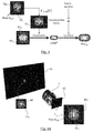
- Figure 1 depicts elements of a system for calibrating a plenoptic camera according to an embodiment of the present disclosure.
- Such a plenoptic camera is an optical system 1 comprising a main lens 10 (or a set of lenses, which may be represented synthetically as a single main lens), and a microlens array 11, located between the main lens 10 and a sensor 12.
- the right hand side of figure 1 with respect to main lens 10 and microlens array 11 corresponds to the image space of the plenoptic camera, where the imaging photosensor 12 captures an image.
- the left hand side of figure 1 with respect to main lens 10 corresponds to the object space, i.e. the observed scene in front of the main lens.
- One or several light sources emit light from the object space towards optical system 1.
- a multiple source point emitting device of known relative position, emissive power and emitting diagram (beam pattern) may be used, which may consist for example in several light sources arranged in a grid or lattice.
- a monitor or projection display may also be used.
- a projector with corrected uniformity and using a diffusing screen is used.
- Part of the emitted light is received on a reference pixel P ref on sensor 12.
- such a pixel beam comprises a part 21 located in the object space and a part 22 located in the image space.
- the chief ray of this pixel beam is denoted as 2.
- scene points may have different light paths to the sensor (e.g. through two or more microlenses 11).
- a given light path from the observed object space to the image plane is identified.
- Such a light path is defined by an entrance pupil, i.e.:
- the light source and sensor 12 are supposed linear or calibrated to linear in their electronic signal to light amplitude transform (for the source) and light amplitude to electronic signal transform (for the sensor 12).
- an initial phase is carried out, aiming at determining a local source space to image space homomorphism.
- such an initial phase is done by classical calibration technique to obtain extrinsic parameters, such as described for example by Zhang, Zhengyou in "A flexible new technique for camera calibration.” Pattern Analysis and Machine Intelligence, IEEE Transactions on 22, no. 11 (2000): 1330-1334 .
- Figures 2A and 2B show the image spot formed on sensor 12 of the plenoptic camera of figure 1 , respectively before and after such a source spot adjustment.
- the image spot of figure 2A before source spot adjustment, shows an ovoid shape, schematically illustrated in dashed lines, which surrounds two main pixels. The upper one is chosen as a reference pixel P ref .
- the source spot will be iteratively adjusted, such that the image spot of figure 2A is transformed into the image spot of figure 2B , which centroid corresponds to, or is superposed with, the centroid of the reference pixel P ref .
- the image spot now shows a circular shape, also shown in dashed lines, which encloses five main pixels, and which center of symmetry corresponds to reference pixel P ref .
- the iterative adjustment of the source pattern in order to obtain a pixel centered and symmetric image pattern, may be carried out according to the following steps:
- Figures 4A and 4B schematically depict the optical system for calibrating the plenoptic camera of figure 1 , and notably the source and image spots before and after iterative adjustment.
- the light source is a screen 40 on which is displayed a source spot consisting in a 5x5 array 44 1 of source points of different intensities.
- the source spot 41 1 shows an overall circular shape, shown in dashed lines.
- Light from source spot 41 1 travels through an optical system 1 (the plenoptic camera of figure 1 , or more generally any kind of optical system of any type) and forms an image spot 42 1 on the focal plane 43 of the optical system 1.
- image spot comprises a 5x6 array 46 1 of source point of different intensities and shows the ovoid shape 42 1 already described in relation to figure 2A .
- the image spot comprises a 5x7 array 46 2 of source points and now shows an overall circular shape 42 2 , shown in dashed lines, and which center of symmetry corresponds to the centroid of reference pixel P ref .
- Such an image spot 42 2 corresponds to the image spot already described in relation to figure 2B .
- the shape of the source pattern has also been modified: after iterative adjustment, the source spot 41 2 shows an elongated ovoid shape. Its size has also been modified and the source spot now consists in a 5x6 array 44 2 of source points of different intensities. Its centroid or maximum 45 provides the intersection of the chief ray 2 with the source plane. This intersection combined with the light path entrance pupil 4 center provides the chief ray 2 associated with pixel P ref .
- step S5 consists in analyzing the resultant source spot pattern, after iterative adjustment, to determine its centroid, in order to characterize its chief ray.
- Step S6 comprises analyzing the resultant source spot and image spot patterns to determine their extensions in the object and image spaces respectively. It is schematically illustrated in figure 3 .
- the source spot S after iterative adjustment 41 2 , 44 2 is deconvolved by this resultant spot 30.
- This myopic (as T I ⁇ S ( I ) is potentially inaccurate) deconvolution provides the local point spread function (LPSF') if light was travelling from image to source. It is actually recalled that myopic deconvolution occurs when the PSF (deconvolution kernel) is partially known. There is then the need to solve both the deconvolved object and the PSF (see for example
- This local point spread function LPSF' is then convolved with a transform of a box filter ⁇ representing the fill function of the pixel, to give the pixel beam profile ( PBP ref ) for P ref at source distance.
- PBP ref LPSF ′ * T I ⁇ S ⁇
- the pixel beam is characterized.
- Knowledge of the optical design provides the light path entrance pupil characteristics and the information whether the pixel beam is converging or diverging when crossing the source plane. In this way, all P ref pixel beam geometric characteristics are obtained.
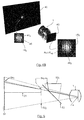
- Figures 5 and 6 describe an alternate embodiment, according to which it is not necessary to have knowledge of the optical system design (knowledge of the entrance pupil of a determined light path) to fully characterize the pixel beam.
- a plenoptic system may be described with a hundred entrance pupils defining a hundred light paths, e.g. in a 10x10 grid.
- Figure 5 depicts an alternate embodiment to figure 1 , in which at least two source point emitting devices are virtually placed at different distances from the camera device 1 to be characterized and calibrated.
- the light sources of figure 5 are multiple source point emitting devices (for example several light sources arranged in a grid or lattice) of known relative position, emissive power and emitting diagram (beam pattern).
- a monitor or projection display can be used.
- a projector with corrected uniformity and using a diffusing screen is an advantageous solution.
- the source point emitting devices are placed at two distinct distances of the camera to calibrate, for example covering a same field of view and with emitting elements of the similar angular resolution when observed from the acquisition device.
- a first light source is located at source plane 51, while a second light source is located at source plane 52 1 .
- the light sources are two projection screens or monitors, with the second light source 52 1 being redirected by means of a beam splitter 53.
- plane 52 1 corresponds to the actual source plane of the second light source
- plane 52 2 corresponds to its virtual position, as induced by the use of the beam splitter 53.
- optical system 1 designates a camera (with potentially multiple light paths) for which correspondence is sought between pixels on one or several sensor plane(s) and beams in the observed object space.
- Numerical reference 54 1 designates a source spot on the first source plane 51
- numerical reference 54 2 designates a source spot on the second source plane 52 1 , 52 2
- Source spots 54 1 and 54 2 located at different distances from optical system 1, are displayed sequentially, and they are both iteratively adjusted, as described previously in relation to figures 1 to 4B .
- Such a specific screen is then placed in the virtual second source plane 52 2 on figure 5 .
- the screen in the second source plane 52 2 is in its transparent state.
- the screen in the second source plane 52 2 starts emitting a second source spot 54 2 towards optical system 1.
- the screen is first located at the first distance to the image acquisition device. Steps S51 to S54 are carried out for the screen in this first position. The screen is then displaced from the first position to a second position, at a second distance to the image acquisition device. Steps S55 to S59 are then carried out for the screen located at the second distance to the image acquisition device. Step S60 is then executed.
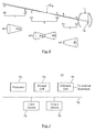
- Figure 7 shows a schematic block diagram illustrating an example of parts of a system for calibrating an image acquisition device according to an embodiment of the present disclosure.
- An apparatus 70 illustrated in Figure 7 includes a processor 71, a storage unit 72, an input device 73, an output device 74, and an interface unit 75 which are connected by a bus 76.
- constituent elements of the computer apparatus 70 may be connected by a connection other than a bus connection using the bus 76.
- the processor 71 controls operations of the apparatus 70.
- the storage unit 72 stores at least one program to be executed by the processor 71, and various data, including data relating to the adjusted source spots, parameters used by computations performed by the processor 71, intermediate data of computations performed by the processor 71, and so on.
- the processor 71 may be formed by any known and suitable hardware, or software, or a combination of hardware and software.
- the processor 71 may be formed by dedicated hardware such as a processing circuit, or by a programmable processing unit such as a CPU (Central Processing Unit) that executes a program stored in a memory thereof.
- CPU Central Processing Unit
- the storage unit 72 may be formed by any suitable storage or means capable of storing the program, data, or the like in a computer-readable manner. Examples of the storage unit 72 include non-transitory computer-readable storage media such as semiconductor memory devices, and magnetic, optical, or magneto-optical recording media loaded into a read and write unit.
- the program causes the processor 71 to perform a process for calibrating an image acquisition device according to an embodiment of the present disclosure as described previously.
- the input device 73 may be formed by a keyboard, a pointing device such as a mouse, or the like for use by the user to input commands.
- the output device 74 may be formed by a display device to display, for example, the calibration data of the image acquisition device, including the geometric characteristics of the pixel beams.
- the input device 73 and the output device 74 may be formed integrally by a touchscreen panel, for example.
- the interface unit 75 provides an interface between the apparatus 70 and an external apparatus.
- the interface unit 75 may be communicable with the external apparatus via cable or wireless communication.
- the external apparatus may be the image acquisition device 1 and the light sources 40, 51, 52.
- the adjusted source spots displayed by the light sources 40, 51, 52 can be input from the light sources to the apparatus 70 through the interface unit 75, then stored in the storage unit 72.
- processor 71 may comprise different modules and units embodying the functions carried out by apparatus 70 according to embodiments of the present disclosure, such as:
- such a processor 71 also comprises a computing unit for determining a homomorphic transform between a source plane and an image plane of the image acquisition device, and the module for adjusting comprises a feedback loop for iteratively modifying the light source pattern to obtain the target image pattern, which makes use of an inverse homomorphic transform of a difference between the image pattern and the target image pattern.
- the analyzing unit also comprises:
- the processor 71 may also comprise:
- a correction module is added on the measured/computed first light source pattern centroid positions to compensate for the deviation of light produced by refraction caused by either the beam splitter or the second light source glass substrate when traversed by the first light source emitted light.
- modules and units may also be embodied in several processors 71 communicating and co-operating with each other.
- the present disclosure thus provides a system and method allowing precise identification of chief rays in the observed object space corresponding to individual pixels of a light field sensor. It also allows identification of pixel beams (position, orientation, shape in the observed object space), in their extension around the chief rays. It thus provides a precise technique for calibrating all kinds of image acquisition devices, including light field data acquisition devices.
Landscapes
- Engineering & Computer Science (AREA)
- Physics & Mathematics (AREA)
- General Physics & Mathematics (AREA)
- Theoretical Computer Science (AREA)
- Computer Vision & Pattern Recognition (AREA)
- Biomedical Technology (AREA)
- Health & Medical Sciences (AREA)
- General Health & Medical Sciences (AREA)
- Multimedia (AREA)
- Signal Processing (AREA)
- Geometry (AREA)
- Image Processing (AREA)
- Studio Devices (AREA)
Abstract
- emitting at least one light source pattern in an object space of the image acquisition device;
- adjusting one of the source patterns until an image pattern of the source pattern formed on a sensor (43) of the image acquisition device exhibit a shape which centroid corresponds to a centroid of a reference pixel (Pref) of the sensor, called a target image pattern (422, 462);
- analyzing the adjusted source pattern (412, 442) and estimating therefrom at least one characteristic of a pixel beam directed to the reference pixel from the adjusted source pattern.
Description
- The present disclosure relates to image or video camera calibration. More precisely, the present disclosure generally relates to a method and a system for calibrating an image acquisition device, notably, but not exclusively, a plenoptic or multi-lens camera or a camera array.
- The present section is intended to introduce the reader to various aspects of art, which may be related to various aspects of the present invention that are described and/or claimed below. This discussion is believed to be helpful in providing the reader with background information to facilitate a better understanding of the various aspects of the present invention. Accordingly, it should be understood that these statements are to be read in this light, and not as admissions of prior art.
- Image acquisition devices project a three-dimensional scene onto a two-dimensional sensor. During operation, a conventional capture device captures a two-dimensional (2-D) image of the scene representing an amount of light that reaches a photosensor (or photodetector or photosite) within the device. However, this 2-D image contains no information about the directional distribution of the light rays that reach the photosensor (which may be referred to as the light-field).
- Moreover, it is more and more frequent to post-process the image data captured by the sensor, and to run computational photography algorithms on the acquired signals.
- However, in order for such image data processing to be performed correctly, it is necessary to have accurate calibration data relating to the image acquisition device used to capture such image or video data.
- Notably, when considering a sensor device observing an object space from the image space of an optical system, it is necessary to estimate, for each pixel of the sensor, to which direction(s), or beam(s), it corresponds in the object space (i.e. which portion of the object space is sensed by this pixel). In the present disclosure, the terms "object space" and "image space" respectively stand for the input and output optical spaces usually defined in the optical design discipline. Hence, the "object space" is the observed scene in front of the main lens of an image acquisition device, while the "image space" is the optical space after the optical system of the image acquisition device (main lens, microlenses, ...) where the imaging photosensor captures an image.
- Among the required calibration data, what is first needed is to identify the chief ray direction in the object space of the beam corresponding to a sensor pixel. A second need is to know the (angular) shape of the geometric beam surrounding the chief ray, and sensed by the pixel.
- Such a need is well known in the art. In "Spatio-Angular Resolution Tradeoffs in Integral Photography", Rendering Techniques 2006 (2006): 263-272, Todor Georgeiv et al. express it as follows: "In order to reconstruct the true irradiance corresponding to the illuminated part of each pixel we would need to know exactly what percentage of it has been illuminated, and correct for that in software. In other words, we would need very precise calibration of all pixels in the camera. However, captured pixel values are affected by tiny misalignments: A misalignment of a micrometer can change a boundary pixel value by more than 10%. This problem gets very visible when the lenslets get smaller."
- According to known prior art techniques, optical systems calibration mainly use checkerboards or grids of points in the object space to estimate the position of corners or intersection points on the acquired images in the image space. For a given optical configuration (a given zoom/focus of the optical acquisition device), grid points or corners positions are estimated with sub-pixel image processing techniques, and these estimates are provided to a model generalizing the estimated positions to the entire field of view.
- Such a perspective projection model is usually taken as a starting point for optical acquisition devices calibration. It is then supplemented with distortion terms, in order to get very precise calibration of all pixels in the camera.
- In " A Generic Camera Model and Calibration Method for Conventional, Wide-Angle, and Fish-Eye Lenses", Pattern Analysis and Machine Intelligence, IEEE Transactions on 28, no. 8 (2006): 1335-1340, Kannala et al. consider that the perspective projection model is not suitable for fish-eye lenses, and suggest to use a more flexible radially symmetric projection model. This calibration method for fish-eye lenses requires that the camera observe a planar calibration pattern.
- In " Multi-media Projector-Single Camera Photogrammetric System For Fast 3d Reconstruction", International Archives of Photogrammetry, Remote Sensing and Spatial Information Sciences, Commission V Symposium, pp. 343-347. 2010, V. A. Knyaz proposes the use of a multimedia projector to simultaneously calibrate several cameras in a 3D reconstruction context.
- Existing calibration methods hence rely on a global model transforming the geometry in the object space to the geometry in the image space. However, such prior art techniques are not suited for light field acquisition devices, which show a complex design and embed optical elements like lenslet arrays, which do not always follow specifications with all the required precision.
- It is actually recalled that light-field capture devices (also referred to as "light-field data acquisition devices") have been designed to measure a four-dimensional (4D) light-field of the scene by capturing the light directions from different viewpoints of that scene. Thus, by measuring the amount of light traveling along each beam of light that intersects the photosensor, these devices can capture additional optical information (information about the directional distribution of the bundle of light rays) for providing new imaging applications by post-processing. The information acquired/obtained by a light-field capture device is referred to as the light-field data.
- Light-field capture devices are defined herein as any devices that are capable of capturing light-field data. There are several types of light-field capture devices, among which:
- plenoptic devices, which use a microlens array placed between the image sensor and the main lens, as described in document
US 2013/0222633 ; - a camera array, as described by Wilburn et al. in "High performance imaging using large camera arrays." ACM Transactions on Graphics (TOG) 24, no. 3 (2005): 765-776 and in patent document
US 8514491 B2 . - For light field acquisition devices, a precise model of the optics (including defects such as microlens array deformations or misalignment) is more complex than with classical single pupil optical systems. Moreover, with light field acquisition devices, blur or vignetting can affect image forming, distorting the relationship between a source point and its image on the sensor. Last, the notion of stationary Point Spread Function, which is used when calibrating conventional image acquisition devices, does not hold for light field acquisition devices.
- It is hence necessary to provide calibration techniques, which are suited for calibrating light field acquisition devices.
- Specific calibration methods and models have hence been proposed for plenoptic or camera arrays acquisition, as in " Using Plane + Parallax for Calibrating Dense Camera Arrays", Computer Vision and Pattern Recognition, 2004. CVPR 2004. Proceedings of the 2004 IEEE Computer Society Conference on, vol. 1, pp. I-2. IEEE, 2004 by Vaish et al. This document describes a procedure to calibrate camera arrays used to capture light fields using a planar + parallax framework.
- However, such a technique does not allow determining with enough precision the chief ray position and direction estimation in the object space, nor the geometrical characteristics of the object space region seen by a given pixel. Such an object space region may also be called a pixel beam in the present disclosure.
- It would hence be desirable to provide a new technique for calibrating image acquisition devices, which would allow calibrating light field acquisition devices, and which would not show the drawbacks of the prior art techniques. More precisely, it would be desirable to provide a new technique for calibrating image acquisition devices, which would allow estimating accurately characteristics of a pixel beam directed to a given pixel on a sensor of the image acquisition device.
- According to an embodiment, a method of calibrating an image acquisition device is provided, which comprises:
- emitting at least one light source pattern in an object space of the image acquisition device;
- adjusting one of the source patterns until an image pattern of the source pattern formed on a sensor of the image acquisition device exhibit a shape which centroid corresponds to a centroid of a reference pixel of the sensor, called a target image pattern;
- analyzing the adjusted source pattern and estimating therefrom at least one characteristic of a pixel beam directed to the reference pixel from the adjusted source pattern.
- The present disclosure thus relies on a novel and inventive approach for calibrating image acquisition devices, whether conventional or light-field acquisition devices, which may be dedicated to capturing images and/or videos. In the foregoing, the generic term "image acquisition device" is used for designating all these devices, whatever their characteristics and features.
- Actually, such a method, as will be apparent in the foregoing, allows improving the precision of the chief ray position and direction estimation over the prior art techniques, as well as knowing the geometrical characteristics of the pixel beam corresponding to a given pixel on the sensor.
- It relies on a simple two-step approach, consisting in:
- adjusting a source spot to obtain an image spot exhibiting a shape centered on a reference pixel of the sensor;
- estimating pixel beam geometric characteristics from the source spot geometry and from knowledge on the optical system.
- A multiple source point emitting device (for example several light sources arranged in a grid or lattice) of known relative position, emissive power and emitting diagram (or beam pattern) emit one or several light source patterns. In an embodiment, a monitor or projection display can be used. In another embodiment, a projector with corrected uniformity and using a diffusing screen is used to emit light source patterns.
- The light source patterns are emitted toward an image acquisition device, such as a camera (with potentially multiple light paths), for which correspondence is sought between pixels on one or several sensor plane(s) and beams in the observed object space. The camera includes optical elements projecting the observed object space into the sensor plane(s) (e.g. including a main lens and optionally microlenses, or including multiple camera lenses like in a camera array configuration).
- A light path is identified from the observed object space to the image plane, and is defined by an entrance pupil (e.g. one of multiple microlenses pupils retro-images or one of multiple cameras entrance pupils in a camera array. Actually, in plenoptic cameras, some pixels may have different light paths to the scene, e.g. through two or more microlenses).
- By easy adjustment of the light source pattern (position and extension) so that the acquired image on the sensor has a defined shape, the method of the present disclosure allows to precisely characterize the pixel beam, which reaches a given pixel on the sensor.
- By centroid of a shape, it is meant here, and throughout this document, the arithmetic mean position of all the points in the shape.
- According to an embodiment, such a method also comprises determining a homomorphic transform between a source plane and an image plane of the image acquisition device, and said adjusting comprises iteratively modifying said source pattern to obtain said target image pattern, an inverse homomorphic transform of a difference between said image pattern and said target image pattern being determined at each iteration of said iteratively modifying step.
- The method of the present disclosure thus relies on an initial phase, allowing determining a local source space to image space homomorphism, which may be done by classical calibration techniques. In an alternate embodiment, this homomorphism may be determined by emitting a non-symmetric light source pattern including several anchor points, and by estimating an homomorphic transform approximation between the source plane and the image plane linking the source and image patterns. This homomorphic transform can be approximated by knowing the optical system model for the given light path in the vicinity of the reference pixel and of the source point corresponding to this reference pixel.
- This homomorphic transform is used in an iterative process of adjusting the light source pattern until the image pattern formed on the sensor shows the shape of a target image pattern. Such an iterative process allows achieving a great precision.
- According to an embodiment, said target image pattern is an image pattern exhibiting central symmetry centered on the reference pixel. Hence, the centroid of the reference pixel corresponds to the center of symmetry of the target image pattern.
- According to an embodiment, analyzing the adjusted source pattern comprises determining a centroid of the adjusted source pattern, and the estimating comprises determining a chief ray of the pixel beam, said chief ray being defined by the centroid of the adjusted source pattern and by a center of an entrance pupil through which the pixel beam reaches the reference pixel.
- Actually, the source spot centroid or maximum provides the intersection of the chief ray with the source plane. This intersection, combined with the light path entrance pupil center, provides the chief ray associated with the reference pixel.
- According to an embodiment, said estimating also comprises:
- deconvolving the adjusted source pattern by an inverse homomorphic transform of the target image pattern, providing a local point spread function;
- convolving the local point spread function with a transform of a filter representing a pixel fill function providing a profile of the pixel beam for the reference pixel in the source plane.
- Such an analysis of the resultant source spot and image spot patterns allows determining their extensions in the object and image spaces respectively.
- By combining this pixel beam profile with the light path entrance pupil, the pixel beam is characterized. Knowledge of the optical design of the used optical system provides the light path entrance pupil characteristics and the information whether the pixel beam is converging or diverging when crossing the source plane. All pixel beam geometric characteristics are thus obtained.
- According to another embodiment, such a method comprises alternately emitting a first light source pattern at a first distance to the image acquisition device in the object space and a second light source pattern at a second distance to the image acquisition device distinct from the first distance in the object space,
said step of determining an image pattern and said step of adjusting the source pattern are carried out for the first light source pattern and for the second light source pattern with a first target image pattern for the first light source pattern and a second target image pattern for the second light source pattern both centered on a same reference pixel,
and said analyzing step comprises analyzing the adjusted first source pattern and the adjusted second source pattern in order to estimate the at least one characteristic of the pixel beam directed to the reference pixel. - Hence, according to this embodiment, the method disclosed previously in this document is implemented with at least two source point emitting devices virtually placed at different distances from the image acquisition device to be characterized. The local source spot adjustment phase is achieved in two distinct source planes. It is hence not necessary anymore to have precise optical design knowledge in order to evaluate pixel beams geometry.
- According to an embodiment, such a method also comprises:
- emitting a part of the first light source pattern and determining an associated first image pattern;
- evaluating a sign of a source versus image magnification from the part of the first light source pattern and from the associated first image pattern;
- emitting a part of the second light source pattern having the same geometry as the part of the first light source pattern, and determining an associated second image pattern;
- evaluating a sign of a source versus image magnification from the part of the second light source pattern and from the associated second image pattern;
- comparing both evaluated signs and determining therefrom a shape of the pixel beam between a plane located at the first distance and a plane located at the second distance.
- Actually, if no knowledge about the optical design is available, an uncertainty remains about the beam shape when knowing only the profile of the beam in two section planes corresponding to both source planes. This uncertainty results from the position of the source planes relative to the plane of smallest cross-section in the beam (i.e. the focus point or reference pixel conjugate point).
- However, if the source versus image magnification has the same sign for both light source patterns, it implies that the beam between both source planes has a truncated cone shape. On the contrary, if both magnifications have opposite signs, the reference pixel conjugate point is located between both source planes, and the beam between the first source plane and the second source plane has a double cone shape.
- The present disclosure also concerns a computer program product downloadable from a communication network and/or recorded on a medium readable by a computer and/or executable by a processor, comprising program code instructions for implementing a method as described previously.
- The present disclosure also concerns a non-transitory computer-readable medium comprising a computer program product recorded thereon and capable of being run by a processor, including program code instructions for implementing a method as described previously.
- Such computer programs may be stored on a computer readable storage medium. A computer readable storage medium as used herein is considered a non-transitory storage medium given the inherent capability to store the information therein as well as the inherent capability to provide retrieval of the information therefrom. A computer readable storage medium can be, for example, but is not limited to, an electronic, magnetic, optical, electromagnetic, infrared, or semiconductor system, apparatus, or device, or any suitable combination of the foregoing. It is to be appreciated that the following, while providing more specific examples of computer readable storage mediums to which the present principles can be applied, is merely an illustrative and not exhaustive listing as is readily appreciated by one of ordinary skill in the art: a portable computer diskette; a hard disk; a read--only memory (ROM); an erasable programmable read--only memory (EPROM or Flash memory); a portable compact disc read--only memory (CD-ROM); an optical storage device; a magnetic storage device; or any suitable combination of the foregoing.
- The present disclosure also concerns a system for calibrating an image acquisition device comprising:
- a first light source able to emit at least a first light source pattern in an object space of the image acquisition device;
- the image acquisition device comprising at least one sensor on which one of said emitted first light source patterns forms at least one first image pattern;
- a module for adjusting said first light source pattern until one of said first image patterns exhibit a shape which centroid corresponds to a centroid of a reference pixel of said sensor, called a target first image pattern;
- an analyzing unit for analyzing the adjusted first light source pattern and for estimating therefrom at least one characteristic of a pixel beam directed to the reference pixel from the adjusted first light source pattern.
- As described previously in relation with the corresponding method, the first light source may be a multiple source point emitting device (for example several light sources arranged in a grid or lattice). A monitor or projection display can also be used, as well as a projector with corrected uniformity and using a diffusing screen.
- More generally, all the assets and features described previously in relation to the method for calibrating an image acquisition device also apply to the present system for calibrating an image acquisition device.
- According to an embodiment, such a system also comprises a computing unit for determining a homomorphic transform between a source plane and an image plane of the image acquisition device, and said module for adjusting comprises a feedback loop for iteratively modifying the first light source pattern to obtain the target first image pattern, an inverse homomorphic transform of a difference between the first image pattern and the target first image pattern being determined at each iteration of said feedback loop. According to an embodiment, said analyzing unit is able to determine:
- a centroid of said adjusted first light source pattern, and
- a chief ray of said pixel beam, said chief ray being defined by said centroid of said adjusted first light source pattern and by a center of an entrance pupil through which said pixel beam reaches said reference pixel.
- According to an embodiment, said analyzing unit also comprises:
- a deconvolving module for deconvolving the adjusted first light source pattern by an inverse homomorphic transform of the target first image pattern, providing a local point spread function;
- a convolving module for convolving the local point spread function with a transform of a filter representing a pixel fill function, providing a profile of the pixel beam for the reference pixel in the source plane.
- According to an embodiment, such a system also comprises a second light source able to emit a second light source pattern in an object space of the image acquisition device, the first light source being located at a first distance to the image acquisition device and the second light source being located at a second distance to the image acquisition device distinct from the first distance.
- According to an embodiment, such a system also comprises a beam splitter separating the first and second light sources.
- Such a beam splitter allows virtually placing the first and second light sources at different distances from the image acquisition device. For example, such a beam splitter separates two projection screens or monitors covering a same field of view and with emitting elements of similar angular resolution when observed from the acquisition device.
- According to an embodiment, the second light source is located between the first light source and the image acquisition device, and the
second light source is a screen able to take: - a transparent state in which the first light source pattern travels through the screen towards the image acquisition device;
- an emitting state able to emit a second light source pattern in an object space towards the image acquisition device.
- With this alternate embodiment, both light sources may be placed in the same direction with respect to the image acquisition device, at different distances, without the need to use a beam splitter.
- According to an embodiment, such a system also comprises:
- an emitting control unit for controlling that the first light source emits a part of the first light source pattern;
- an emitting control unit for controlling that the second light source emits a part of the second light source pattern having the same geometry as the part of the first light source pattern;
- an evaluating module for evaluating a sign of a source versus image magnification from the part of the first light source pattern and from an associated first image pattern;
- an evaluating module for evaluating a sign of a source versus image magnification from the part of the second light source pattern and from an associated second image pattern;
- a comparison module for comparing both evaluated signs and determining therefrom a shape of the pixel beam between a plane located at the first distance and a plane located at the second distance.
- It is to be understood that both the foregoing general description and the following detailed description are exemplary and explanatory and are not restrictive of the invention, as claimed.
- It must also be understood that references in the specification to "one embodiment" or "an embodiment", indicate that the embodiment described may include a particular feature, structure, or characteristic, but every embodiment may not necessarily include the particular feature, structure, or characteristic. Moreover, such phrases are not necessarily referring to the same embodiment. Further, when a particular feature, structure, or characteristic is described in connection with an embodiment, it is submitted that it is within the knowledge of one skilled in the art to affect such feature, structure, or characteristic in connection with other embodiments whether or not explicitly described.
- The invention can be better understood with reference to the following description and drawings, given by way of example and not limiting the scope of protection, and in which:
-
Figure 1 depicts elements of a system for calibrating a plenoptic camera according to an embodiment of the present disclosure; -
Figures 2A and 2B show the image spot formed on a sensor of the plenoptic camera offigure 1 , respectively before and after source spot adjustment according to the method of the present disclosure; -
Figure 3 is a schematic diagram illustrating the iterative process according to embodiments of the present disclosure for determining the pixel beam profile from source and image spots; -
Figure 4A illustrates the optical system for calibrating an image acquisition device according to an embodiment of the present disclosure, and notably the source and image spots before iterative adjustment; -
Figure 4B illustrates the optical system for calibrating an image acquisition device according to an embodiment of the present disclosure, and notably the source and image spots after iterative adjustment; -
Figure 5 depicts a calibration bench structure using two light sources according to an embodiment of the present disclosure; -
Figure 6 illustrates the pixel beam shape depending on the positions of the source planes offigure 5 ; -
Figure 7 illustrates a schematic block diagram illustrating an example of part of a system for calibrating an image acquisition device according to the present disclosure. - The components in the figures are not necessarily to scale, emphasis instead being placed upon illustrating the principles of the invention.
- The present invention will be described more fully hereinafter with reference to the accompanying figures, in which embodiments of the invention are shown. This invention may, however, be embodied in many alternate forms and should not be construed as limited to the embodiments set forth herein. Accordingly, while the invention is susceptible to various modifications and alternative forms, specific embodiments thereof are shown by way of example in the drawings and will herein be described in detail. It should be understood, however, that there is no intent to limit the invention to the particular forms disclosed, but on the contrary, the invention is to cover all modifications, equivalents, and alternatives falling within the spirit and scope of the invention as defined by the claims. Like numbers refer to like elements throughout the description of the figures.
- It will be understood that, although the terms first, second, etc. may be used herein to describe various elements, these elements should not be limited by these terms. These terms are only used to distinguish one element from another. For example, a first element could be termed a second element, and, similarly, a second element could be termed a first element without departing from the teachings of the disclosure.
- While not explicitly described, the present embodiments and variants may be employed in any combination or sub-combination.
- It must be noted that, in the foregoing, the exemplary embodiments are described in relation to a light-field acquisition device, such as a plenoptic camera. However, the scope of the invention must not be limited to such plenoptic devices, and applies for any kind of image acquisition device, whether a conventional device or a light-field acquisition device.
-
Figure 1 depicts elements of a system for calibrating a plenoptic camera according to an embodiment of the present disclosure. - Such a plenoptic camera is an
optical system 1 comprising a main lens 10 (or a set of lenses, which may be represented synthetically as a single main lens), and amicrolens array 11, located between themain lens 10 and asensor 12. - The right hand side of
figure 1 with respect tomain lens 10 andmicrolens array 11 corresponds to the image space of the plenoptic camera, where theimaging photosensor 12 captures an image. The left hand side offigure 1 with respect tomain lens 10 corresponds to the object space, i.e. the observed scene in front of the main lens. - For this plenoptic camera (with potentially multiple light paths), correspondence is sought between pixels on one or several sensor plane(s) and beams in the observed object space.
- One or several light sources (not illustrated in
figure 1 ) emit light from the object space towardsoptical system 1. A multiple source point emitting device of known relative position, emissive power and emitting diagram (beam pattern) may be used, which may consist for example in several light sources arranged in a grid or lattice. A monitor or projection display may also be used. In an embodiment, a projector with corrected uniformity and using a diffusing screen is used. - Part of the emitted light is received on a reference pixel Pref on
sensor 12. - In order to calibrate the plenoptic camera of
figure 1 , it is important to identify the chief ray direction in the object space of the beam corresponding to reference pixel Pref. It is also interesting to know the angular shape of the geometric beam surrounding the chief ray, and sensed by the reference pixel Pref. Of course, such a calibration may be carried out for several reference pixels Pref. Those data, i.e. the chief ray direction in the object space of the beam corresponding to reference pixel Pref and the angular shape of the geometric beam surrounding the chief ray, and sensed by the reference pixel Pref, may be stored as digital files as the result of the calibration of a camera. This digital file may then be transmitted to another device for post-processing images acquired by the calibrated camera. - On
figure 1 , such a pixel beam comprises a part 21 located in the object space and apart 22 located in the image space. The chief ray of this pixel beam is denoted as 2. - It must be recalled that in plenoptic cameras, scene points may have different light paths to the sensor (e.g. through two or more microlenses 11). On
figure 1 , a given light path from the observed object space to the image plane is identified. Such a light path is defined by an entrance pupil, i.e.: - a
physical pupil 3, corresponding to a microlens belonging tomicrolens array 12; - a
virtual entrance pupil 4. - The light source and
sensor 12 are supposed linear or calibrated to linear in their electronic signal to light amplitude transform (for the source) and light amplitude to electronic signal transform (for the sensor 12). - In order to properly calibrate
plenoptic camera 1, an initial phase is carried out, aiming at determining a local source space to image space homomorphism. According to a first embodiment, such an initial phase is done by classical calibration technique to obtain extrinsic parameters, such as described for example by Zhang, Zhengyou in "A flexible new technique for camera calibration." Pattern Analysis and Machine Intelligence, IEEE Transactions on 22, no. 11 (2000): 1330-1334. - In another embodiment, such an initial phase is carried out as follows:
- A non-symmetric pattern including several anchor points is displayed with the emitting device (not shown). The pattern size and localization are designed so that the pattern is imaged on
sensor 12 in the vicinity of a reference pixel P ref ; - An homomorphic transform approximation TS→I is estimated between the source plane and the image plane linking the source and image patterns. Actually, this homomorphic transform is an isomorphism as it relates two planes. For example TS→I is a linear transform represented by a 2x2 matrix transforming 2D coordinates of the source plane into 2D coordinates of the image plane. TS→I can be approximated by knowing the optical system model for the given light path in the vicinity of Pref and of the source point corresponding to Pref . Optimally TS→I is invertible to give TI→S, the inverse transform from the image space to the source space.
- Once this initial phase has been executed, a local source spot adjustment phase starts, which aims at precise pixel beam characterization:
- first, a source spot (composed of several source points) is switched on in the object space (step S1);
- this source spot may be imaged on several regions of the
sensor 12. One of these regions is chosen, and the corresponding image spot is identified (step S2); - a close to central pixel is selected in the image spot, which is called a reference pixel Pref (step S3). For example, this reference pixel may be the image spot centroid nearest neighbor;
- the source spot (namely, the source points intensities) is iteratively modified to obtain a (minimal radius) image spot exhibiting central symmetry centered on the reference pixel Pref (step S4). The inverse homomorphic transform TI→S of the difference between the image spot and an optimally centered spot is used at each iterative step to adjust the source spot or source pattern.
-
Figures 2A and 2B show the image spot formed onsensor 12 of the plenoptic camera offigure 1 , respectively before and after such a source spot adjustment. The image spot offigure 2A , before source spot adjustment, shows an ovoid shape, schematically illustrated in dashed lines, which surrounds two main pixels. The upper one is chosen as a reference pixel Pref. The source spot will be iteratively adjusted, such that the image spot offigure 2A is transformed into the image spot offigure 2B , which centroid corresponds to, or is superposed with, the centroid of the reference pixel Pref. Onfigure 2B , the image spot now shows a circular shape, also shown in dashed lines, which encloses five main pixels, and which center of symmetry corresponds to reference pixel Pref. - More precisely, the iterative adjustment of the source pattern, in order to obtain a pixel centered and symmetric image pattern, may be carried out according to the following steps:
- Step IA1: Estimate a translation and scaling in two directions between a given pixel region in image space and the corresponding pixel region of the source space (e.g. exploiting camera extrinsic parameters);
- Step IA2: Define, in the image space coordinate system, a target image pattern (also called reference pattern), which is symmetric and centered on the given pixel, called a reference pixel;
- Step IA3: Apply translation and scaling estimated at step IA1 to the reference pattern defined at step IA2, in order to transform it to the source space coordinate system;
- Step IA4: Define the scaled pattern obtained at step IA3 as the initial source pattern;
- Step IA5: Iterate the following sub-steps, starting with the initial source pattern at the first iteration:
- ∘ Sub-step IA51:
- ▪ Capture the image pattern formed on the sensor from the source pattern;
- ▪ Break to step IA6 if the averaged pixel value difference between the captured image pattern and the target image pattern is lower than a threshold value (for example, lower than 5% of the target pattern peak value);
- ∘ Sub-step IA52:
- ▪ Compute a difference image between the target image pattern of step IA2 and the captured image pattern of step IA51;
- ∘ Sub-step IA53:
- ▪ On the difference image computed at sub-step IA52, determine a maximum positive difference position and amplitude (positive dirac);
- ∘ Sub-step IA54:
- ▪ On the difference image computed at sub-step IA52, determine a maximum negative difference position and amplitude (negative dirac);
- ∘ Sub-step IA55:
- ▪ Build a correction image convolving the combined positive and negative diracs with a circular Gaussian function of locally estimated standard deviation;
- ∘ Sub-step IA56:
- ▪ Scale and translate (with translation and scaling determined at step IA1) the correction image built at sub-step IA55;
- ∘ Sub-step IA57:
- ▪ Add the translated and scaled correction image obtained at sub-step IA56 to the current source pattern;
- ∘ Sub-step IA51:
- Step IA6: Store the last source pattern obtained, i.e. the source pattern yielding a captured image pattern, which averaged pixel value difference between the captured image pattern and the target image pattern is lower than a threshold value. The iteratively adjusted source pattern is thus obtained.
- Step IA7: It is now possible to move to another pixel region.
-
Figures 4A and4B schematically depict the optical system for calibrating the plenoptic camera offigure 1 , and notably the source and image spots before and after iterative adjustment. - In the embodiment of
figures 4A and4B , the light source is ascreen 40 on which is displayed a source spot consisting in a 5x5 array 441 of source points of different intensities. As shown onfigure 4A , before iterative adjustment, the source spot 411 shows an overall circular shape, shown in dashed lines. Light from source spot 411 travels through an optical system 1 (the plenoptic camera offigure 1 , or more generally any kind of optical system of any type) and forms an image spot 421 on thefocal plane 43 of theoptical system 1. Before iterative adjustment of the source spot 411, image spot comprises a 5x6 array 461 of source point of different intensities and shows the ovoid shape 421 already described in relation tofigure 2A . - As shown on
figure 4B , after iterative adjustment, the image spot comprises a 5x7 array 462 of source points and now shows an overall circular shape 422, shown in dashed lines, and which center of symmetry corresponds to the centroid of reference pixel Pref. Such an image spot 422 corresponds to the image spot already described in relation tofigure 2B . However, the shape of the source pattern has also been modified: after iterative adjustment, the source spot 412 shows an elongated ovoid shape. Its size has also been modified and the source spot now consists in a 5x6 array 442 of source points of different intensities. Its centroid or maximum 45 provides the intersection of thechief ray 2 with the source plane. This intersection combined with the lightpath entrance pupil 4 center provides thechief ray 2 associated with pixel Pref. - Hence, step S5 consists in analyzing the resultant source spot pattern, after iterative adjustment, to determine its centroid, in order to characterize its chief ray.
- Step S6 comprises analyzing the resultant source spot and image spot patterns to determine their extensions in the object and image spaces respectively. It is schematically illustrated in
figure 3 . - The image spot I after source spot adjustment 422, 462, which is centered on the reference pixel Pref, undergoes an inverse homomorphic transform TI→S (I). A
resultant spot 30, corresponding to the transform of the image spot to source plane, is obtained. - The source spot S after iterative adjustment 412, 442 is deconvolved by this
resultant spot 30. This myopic (as TI→S (I) is potentially inaccurate) deconvolution provides the local point spread function (LPSF') if light was travelling from image to source. It is actually recalled that myopic deconvolution occurs when the PSF (deconvolution kernel) is partially known. There is then the need to solve both the deconvolved object and the PSF (see for example - The formula to invert to find LPSF' is:
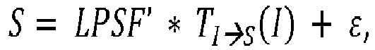
- This local point spread function LPSF' is then convolved with a transform of a box filter Π representing the fill function of the pixel, to give the pixel beam profile (PBPref ) for P ref at source distance.
- By combining this pixel beam profile PBPref with the light
path entrance pupil 4, the pixel beam is characterized. Knowledge of the optical design provides the light path entrance pupil characteristics and the information whether the pixel beam is converging or diverging when crossing the source plane. In this way, all Pref pixel beam geometric characteristics are obtained. -
Figures 5 and6 describe an alternate embodiment, according to which it is not necessary to have knowledge of the optical system design (knowledge of the entrance pupil of a determined light path) to fully characterize the pixel beam. - Actually, as in multiple lens systems, in plenoptic cameras or camera arrays, the realization of the optical system might differ from its optical design, and knowing exactly where pupil entrances are is a challenge in terms of optical modeling. For example, a plenoptic system may be described with a hundred entrance pupils defining a hundred light paths, e.g. in a 10x10 grid.
-
Figure 5 depicts an alternate embodiment tofigure 1 , in which at least two source point emitting devices are virtually placed at different distances from thecamera device 1 to be characterized and calibrated. - Like in the embodiment of
figure 1 , the light sources offigure 5 are multiple source point emitting devices (for example several light sources arranged in a grid or lattice) of known relative position, emissive power and emitting diagram (beam pattern). As well, a monitor or projection display can be used. A projector with corrected uniformity and using a diffusing screen is an advantageous solution. - The source point emitting devices are placed at two distinct distances of the camera to calibrate, for example covering a same field of view and with emitting elements of the similar angular resolution when observed from the acquisition device. A first light source is located at
source plane 51, while a second light source is located atsource plane 521. In the exemplary embodiment offigure 5 , the light sources are two projection screens or monitors, with the secondlight source 521 being redirected by means of abeam splitter 53. Hence,plane 521 corresponds to the actual source plane of the second light source, whileplane 522 corresponds to its virtual position, as induced by the use of thebeam splitter 53. - Like in the embodiment of
figure 1 ,optical system 1 designates a camera (with potentially multiple light paths) for which correspondence is sought between pixels on one or several sensor plane(s) and beams in the observed object space. - Numerical reference 541 designates a source spot on the
first source plane 51, while numerical reference 542 designates a source spot on thesecond source plane optical system 1, are displayed sequentially, and they are both iteratively adjusted, as described previously in relation tofigures 1 to 4B . - More precisely:
- at step S51, a source spot 541 is switched on, in the
first source plane 51; - previously described steps S2 to S4 are applied for a reference pixel Pref with source spot 541 (step S52). In other words, an image spot resulting from source spot 541 is chosen (step S2), a close to central pixel is selected in the image spot, which is called a reference pixel Pref (step S3) and the source spot 541 is iteratively modified to obtain an image spot exhibiting central symmetry centered on the reference pixel Pref (step S4). The inverse homomorphic transform TI→S of the difference between the image spot and an optimally centered spot is used at each iterative step to adjust the source spot or source pattern;
- at step S53, the iteratively adjusted source spot S1 for
source plane 51 is stored (in other words, the digital counts defining the shape and position of the spot are recorded); - at step S54, the first light source in
source plane 51 is switched off; - at step S55, a source spot 542 is switched on in source plane 521 (and hence in
virtual source plane 522, thanks to beam splitter 53). Source spot 542 is homologous to the stored source spot S1 for thefirst source plane 51; - at step S56, with a coarse systematic or iterative method, the source spot 542 on
source plane 521 is modified to place the corresponding image spot in the vicinity of the reference pixel Pref; - previously described steps S2 to S4 (or previously described step S52) are then applied for the reference pixel Pref with the modified source spot on source plane 521 (step S57). It yields an iteratively adjusted source spot S2 for
source plane - at step S58, the iteratively adjusted source spot S2 for
source plane - at step S59, the light source in
source plane - at step S60, the resultant source spots data patterns S1 and S2 are analyzed to determine their extension in the first and second source planes 51 and 521, 522 respectively (in accordance with the method described previously in relation to step S6,
figure 3 ). More precisely:- ∘ the S1 and S2 source spots maxima are joined to provide the chief ray associated with pixel Pref;
- ∘ the deconvolution of each source spot by the inverse transform of the image spot provides the pixel beam profile for Pref at the
first source plane 51 distance and at thesecond source plane
- Such a use of at least two source planes allow a very precise identification of the chief ray and of the beam lateral extensions, even without knowledge of the optical design of
optical system 1. However, an uncertainty remains about the beam shape when knowing only the profile in two section planes, as illustrated infigure 6 . This uncertainty results from the position of the source planes relative to the plane of smallest cross-section in the beam, corresponding to the focus point or to the reference pixel Pref conjugate point. - Actually, as may be observed in
figure 6 : - when the first and second source planes 51 and 52 are both located at a distance to
optical system 1, which is greater than the distance from the reference pixel conjugate point Pref* to optical system 1 (left hand side part offigure 6 ), the pixel beam between the first and second source planes 51 and 52 has a truncated cone shape, with a diameter d1 atfirst source plane 51 greater than its diameter d2 atsecond source plane 52; - when the first and second source planes 51 and 52 are both located at a distance to
optical system 1, which is smaller than the distance from the reference pixel conjugate point Pref* to optical system 1 (left hand side part offigure 6 ), the pixel beam between the first and second source planes 51 and 52 also has a truncated cone shape, but with a diameter d1 atfirst source plane 51 smaller than its diameter d2 atsecond source plane 52; - however, when the reference pixel conjugate point Pref* is located between the
first source plane 51 and thesecond source plane 52, the beam between thefirst source plane 51 and thesecond source plane 52 has a double cone shape. - In order to remove uncertainty in the beam shape, some steps may be added in the process described in relation with
figure 5 : - after step S53, only part of the stored source spot S1 is displayed (step S531). For example, a vertical half S1:2 of stored source spot S1 is displayed in the
first source plane 51. The resulting image spot data I1:2 is stored (step S532); - after step S58, a part of the stored source spot S2 showing the same geometry as the part of the stored source spot S1 displayed at step S531 is displayed (step S581). For example, once again, a vertical half S2:2 of stored source spot S2 is displayed in the
second source plane 52. The resulting image spot data I2:2 is stored (step S582); - at step S61 following step S60, one evaluates from S1:2 and I1:2 on the one hand, and from S2:2 and I2:2 on the other hand, if the source versus image magnification has the same sign or not for the
first source plane 51 and the second source plane 52:- ∘ if the source versus image magnifications show the same sign, the pixel beam between
first source plane 51 andsecond source plane 52 has a truncated cone shape; - ∘ if the source versus image magnifications show different signs, the plane of smallest cross-section in the beam is located between the first and second source planes: the pixel beam between the
first source plane 51 and thesecond source plane 52 has a double cone shape.
- ∘ if the source versus image magnifications show the same sign, the pixel beam between
- Thanks to this embodiment, it is hence possible to derive the whole pixel beam characteristics for a given reference pixel on the sensor, even without knowledge of the optical design of the image acquisition device to be calibrated.
- In an alternate embodiment to
figure 5 , it is possible to design a calibrating system, which does not comprise anybeam splitter 53, if the second light source is a specific screen able to take: - a transparent state in which the light emitted on the
first source plane 51 travels through thescreen 52 towards theimage acquisition device 1; - an emitting state able to emit light towards the
image acquisition device 1. - Such a specific screen is then placed in the virtual
second source plane 522 onfigure 5 . When the first source spot 541 is switched on, the screen in thesecond source plane 522 is in its transparent state. Once the first source spot 541 has been switched off, the screen in thesecond source plane 522 starts emitting a second source spot 542 towardsoptical system 1. - Except for the use of this specific screen, all the steps and features described previously in relation to
figures 5 and6 are executed and apply in the same way. - In another alternate embodiment to
figure 5 , it is also possible to: - execute previously described steps S51 to S54 for a first light source;
- insert a screen as a second light source between the first light source and the device to be calibrated;
- execute steps S55 to S59 for this added screen;
- then execute step S60.
- In yet another alternate embodiment to
figure 5 , it is also possible to use only one screen as both the first light source and the second light source. The screen is first located at the first distance to the image acquisition device. Steps S51 to S54 are carried out for the screen in this first position. The screen is then displaced from the first position to a second position, at a second distance to the image acquisition device. Steps S55 to S59 are then carried out for the screen located at the second distance to the image acquisition device. Step S60 is then executed. - These last two embodiments require a high precision in locating the screens at their exact position.
- All the steps and features described previously in relation to
figures 5 and6 also apply for these last two embodiments. -
Figure 7 shows a schematic block diagram illustrating an example of parts of a system for calibrating an image acquisition device according to an embodiment of the present disclosure. - An
apparatus 70 illustrated inFigure 7 includes aprocessor 71, astorage unit 72, aninput device 73, anoutput device 74, and aninterface unit 75 which are connected by abus 76. Of course, constituent elements of thecomputer apparatus 70 may be connected by a connection other than a bus connection using thebus 76. - The
processor 71 controls operations of theapparatus 70. Thestorage unit 72 stores at least one program to be executed by theprocessor 71, and various data, including data relating to the adjusted source spots, parameters used by computations performed by theprocessor 71, intermediate data of computations performed by theprocessor 71, and so on. Theprocessor 71 may be formed by any known and suitable hardware, or software, or a combination of hardware and software. For example, theprocessor 71 may be formed by dedicated hardware such as a processing circuit, or by a programmable processing unit such as a CPU (Central Processing Unit) that executes a program stored in a memory thereof. - The
storage unit 72 may be formed by any suitable storage or means capable of storing the program, data, or the like in a computer-readable manner. Examples of thestorage unit 72 include non-transitory computer-readable storage media such as semiconductor memory devices, and magnetic, optical, or magneto-optical recording media loaded into a read and write unit. The program causes theprocessor 71 to perform a process for calibrating an image acquisition device according to an embodiment of the present disclosure as described previously. - The
input device 73 may be formed by a keyboard, a pointing device such as a mouse, or the like for use by the user to input commands. Theoutput device 74 may be formed by a display device to display, for example, the calibration data of the image acquisition device, including the geometric characteristics of the pixel beams. Theinput device 73 and theoutput device 74 may be formed integrally by a touchscreen panel, for example. - The
interface unit 75 provides an interface between theapparatus 70 and an external apparatus. Theinterface unit 75 may be communicable with the external apparatus via cable or wireless communication. In this embodiment, the external apparatus may be theimage acquisition device 1 and thelight sources light sources apparatus 70 through theinterface unit 75, then stored in thestorage unit 72. - Although only one
processor 71 is shown onfigure 7 , it must be understood that such a processor may comprise different modules and units embodying the functions carried out byapparatus 70 according to embodiments of the present disclosure, such as: - a module for adjusting the light source pattern(s) until one of the corresponding image patterns exhibit a shape which centroid corresponds to a centroid of a reference pixel of the sensor of
image acquisition device 1; - an analyzing unit for analyzing the adjusted light source pattern and for estimating therefrom characteristics of a pixel beam directed to the reference pixel from the adjusted first light source pattern.
- In a specific embodiment, such a
processor 71 also comprises a computing unit for determining a homomorphic transform between a source plane and an image plane of the image acquisition device, and the module for adjusting comprises a feedback loop for iteratively modifying the light source pattern to obtain the target image pattern, which makes use of an inverse homomorphic transform of a difference between the image pattern and the target image pattern. - In a specific embodiment, which may be combined with the previous one, the analyzing unit also comprises:
- a deconvolving module for deconvolving the adjusted light source pattern by an inverse homomorphic transform of the target image pattern, providing a local point spread function;
- a convolving module for convolving the local point spread function with a transform of a filter representing a pixel fill function, providing a profile of the pixel beam for the reference pixel in the source plane.
- In another specific embodiment corresponding to the process previously described in relation to
figures 5 and6 , theprocessor 71 may also comprise: - an emitting control unit for controlling that a first light source emits a part of a first light source pattern;
- an emitting control unit for controlling that a second light source emits a part of a second light source pattern having the same geometry as the part of the first light source pattern;
- an evaluating module for evaluating a sign of a source versus image magnification from the part of the first light source pattern and from an associated first image pattern;
- an evaluating module for evaluating a sign of a source versus image magnification from the part of the second light source pattern and from an associated second image pattern;
- a comparison module for comparing both evaluated signs and determining therefrom a shape of the pixel beam between a plane located at the first distance (distance from the first light source to the image acquisition device) and a plane located at the second distance (distance from the second light source to the image acquisition device).
- In such an embodiment, whether using a beam splitter or a transparent screen, a correction module is added on the measured/computed first light source pattern centroid positions to compensate for the deviation of light produced by refraction caused by either the beam splitter or the second light source glass substrate when traversed by the first light source emitted light.
- These modules and units may also be embodied in
several processors 71 communicating and co-operating with each other. - The present disclosure thus provides a system and method allowing precise identification of chief rays in the observed object space corresponding to individual pixels of a light field sensor. It also allows identification of pixel beams (position, orientation, shape in the observed object space), in their extension around the chief rays. It thus provides a precise technique for calibrating all kinds of image acquisition devices, including light field data acquisition devices.
Claims (17)
- Method of calibrating an image acquisition device (1) comprising:- emitting at least one light source pattern (411, 441) in an object space of said image acquisition device;- adjusting one of said source patterns until an image pattern (421, 461) of said source pattern formed on a sensor (12) of said image acquisition device exhibit a shape which centroid corresponds to a centroid of a reference pixel (Pref) of said sensor, called a target image pattern (422, 462);- analyzing said adjusted source pattern (412, 442) and estimating therefrom at least one characteristic of a pixel beam (21, 22) directed to said reference pixel from said adjusted source pattern.
- The method of claim 1, wherein it also comprises determining a homomorphic transform (TS→I ) between a source plane and an image plane of said image acquisition device, and wherein said adjusting comprises iteratively modifying said source pattern to obtain said target image pattern, an inverse homomorphic transform (TI→S ) of a difference between said image pattern and said target image pattern being determined at each iteration of said iteratively modifying step.
- The method of claim 1 or 2, wherein said target image pattern is an image pattern exhibiting central symmetry centered on said reference pixel.
- The method of any preceding claim, wherein analyzing said adjusted source pattern comprises determining a centroid of said adjusted source pattern, and wherein said estimating comprises determining a chief ray (2) of said pixel beam, said chief ray being defined by said centroid of said adjusted source pattern and by a center of an entrance pupil (4) through which said pixel beam reaches said reference pixel (Pref).
- The method of any preceding claim, wherein said estimating also comprises:- deconvolving said adjusted source pattern by an inverse homomorphic transform of said target image pattern, providing a local point spread function (LPSF');- convolving said local point spread function with a transform of a filter representing a pixel fill function (π), providing a profile (PBPref) of said pixel beam for said reference pixel in said source plane.
- The method of any preceding claim, wherein it comprises alternately emitting a first light source pattern (541) at a first distance to said image acquisition device (1) in said object space and a second light source pattern (542) at a second distance to said image acquisition device (1) distinct from said first distance in said object space,
and wherein said step of determining an image pattern and said step of adjusting said source pattern are carried out for said first light source pattern and for said second light source pattern with a first target image pattern for said first light source pattern and a second target image pattern for said second light source pattern both centered on a same reference pixel (Pref),
and wherein said analyzing step comprises analyzing said adjusted first source pattern and said adjusted second source pattern in order to estimate said at least one characteristic of said pixel beam directed to said reference pixel. - The method of claim 6, wherein it also comprises:- emitting a part of said first light source pattern and determining an associated first image pattern;- evaluating a sign of a source versus image magnification from said part of said first light source pattern and from said associated first image pattern;- emitting a part of said second light source pattern having the same geometry as the part of said first light source pattern, and determining an associated second image pattern;- evaluating a sign of a source versus image magnification from said part of said second light source pattern and from said associated second image pattern;- comparing both evaluated signs and determining therefrom a shape of said pixel beam between a plane located at said first distance and a plane located at said second distance.
- A computer program product downloadable from a communication network and/or recorded on a medium readable by a computer and/or executable by a processor, comprising program code instructions for implementing a method according to any one of claims 1 to 7.
- A system for calibrating an image acquisition device comprising:- a first light source able to emit at least a first light source pattern in an object space of said image acquisition device;- the image acquisition device comprising at least one sensor on which one of said emitted first light source patterns forms at least one first image pattern;- a module for adjusting said first light source pattern until one of said first image patterns exhibit a shape which centroid corresponds to a centroid of a reference pixel of said sensor, called a target first image pattern;- an analyzing unit for analyzing said adjusted first light source pattern and for estimating therefrom at least one characteristic of a pixel beam directed to said reference pixel from said adjusted first light source pattern.
- The system of claim 9, wherein it also comprises a computing unit for determining a homomorphic transform between a source plane and an image plane of said image acquisition device, and wherein said module for adjusting comprises a feedback loop for iteratively modifying said first light source pattern to obtain said target first image pattern, an inverse homomorphic transform of a difference between said first image pattern and said target first image pattern being determined at each iteration of said feedback loop.
- The system of any preceding claim, wherein said analyzing unit is able to determine:- a centroid of said adjusted first light source pattern, and- a chief ray of said pixel beam, said chief ray being defined by said centroid of said adjusted first light source pattern and by a center of an entrance pupil through which said pixel beam reaches said reference pixel.
- The system of any preceding claim, wherein said analyzing unit also comprises:- a deconvolving module for deconvolving said adjusted first light source pattern by an inverse homomorphic transform of said target first image pattern, providing a local point spread function;- a convolving module for convolving said local point spread function with a transform of a filter representing a pixel fill function, providing a profile of said pixel beam for said reference pixel in said source plane.
- The system of any preceding claim, wherein it also comprises a second light source able to emit a second light source pattern in an object space of said image acquisition device, said first light source being located at a first distance to said image acquisition device and said second light source being located at a second distance to said image acquisition device distinct from said first distance.
- A method for generating data representative of a calibration of an image acquisition device, said method comprising:- acquiring data representative of at least one characteristic of a pixel beam (21, 22) directed to a reference pixel (Pref) of a sensor (12) of said image acquisition device, said data representative of at least one characteristic of a pixel beam (21, 22) being obtained according to the method according to claims 1-7,- generating a data file comprising said acquired data representative of at least one characteristic of a pixel beam (21, 22).
- A device for generating data representative of a calibration of an image acquisition device, said device comprising a processor configured to:- acquire data representative of at least one characteristic of a pixel beam (21, 22) directed to a reference pixel (Pref) of a sensor (12) of said image acquisition device, said data representative of at least one characteristic of a pixel beam (21, 22) being obtained according to the method according to claims 1-7,- generate a data file comprising said acquired data representative of at least one characteristic of a pixel beam (21, 22).
- A digital file comprising data representative of a calibration of an image acquisition device, said data being representative of at least one characteristic of a pixel beam (21, 22) directed to a reference pixel (Pref) of a sensor (12) of said image acquisition device, said data representative of at least one characteristic of a pixel beam (21,22) being obtained according to the method according to claims 1-7.
- The digital file according to claim 16 wherein the data representative of at least one characteristic of a pixel beam (21, 22) comprises a direction, in an object space o the image acquisition device, of a chief ray of the pixel beam corresponding to the reference pixel (Pref).
Applications Claiming Priority (1)
| Application Number | Priority Date | Filing Date | Title |
|---|---|---|---|
| EP15306443.1A EP3144889A1 (en) | 2015-09-17 | 2015-09-17 | Method and system for calibrating an image acquisition device and corresponding computer program product |
Publications (2)
| Publication Number | Publication Date |
|---|---|
| EP3144894A1 true EP3144894A1 (en) | 2017-03-22 |
| EP3144894B1 EP3144894B1 (en) | 2018-06-13 |
Family
ID=54293192
Family Applications (2)
| Application Number | Title | Priority Date | Filing Date |
|---|---|---|---|
| EP15306443.1A Withdrawn EP3144889A1 (en) | 2015-09-17 | 2015-09-17 | Method and system for calibrating an image acquisition device and corresponding computer program product |
| EP16189477.9A Active EP3144894B1 (en) | 2015-09-17 | 2016-09-19 | Method and system for calibrating an image acquisition device and corresponding computer program product |
Family Applications Before (1)
| Application Number | Title | Priority Date | Filing Date |
|---|---|---|---|
| EP15306443.1A Withdrawn EP3144889A1 (en) | 2015-09-17 | 2015-09-17 | Method and system for calibrating an image acquisition device and corresponding computer program product |
Country Status (2)
| Country | Link |
|---|---|
| US (1) | US10319105B2 (en) |
| EP (2) | EP3144889A1 (en) |
Cited By (2)
| Publication number | Priority date | Publication date | Assignee | Title |
|---|---|---|---|---|
| CN110310338A (en) * | 2019-06-24 | 2019-10-08 | 西北工业大学 | A kind of light-field camera scaling method based on multicenter projection model |
| CN112312120A (en) * | 2019-07-30 | 2021-02-02 | 深圳光启空间技术有限公司 | Camera focal plane automatic adjustment system and method |
Families Citing this family (5)
| Publication number | Priority date | Publication date | Assignee | Title |
|---|---|---|---|---|
| EP3279864B1 (en) | 2016-08-05 | 2019-03-06 | Thomson Licensing | A method for obtaining parameters defining a pixel beam associated with a pixel of an image sensor comprised in an optical device |
| KR102689953B1 (en) * | 2018-12-03 | 2024-07-31 | 삼성전자주식회사 | Method and apparatus for calibration |
| EP3848900A1 (en) * | 2020-01-10 | 2021-07-14 | Aptiv Technologies Limited | Methods and systems for calibrating a camera |
| CN113766218B (en) * | 2021-09-14 | 2024-05-14 | 北京集创北方科技股份有限公司 | Position detection method of optical lens, electronic device and storage medium |
| US12457432B2 (en) * | 2022-12-23 | 2025-10-28 | Samsung Electronics Co., Ltd. | ToF sensor including duel emitting units and method for controlling thereof |
Citations (4)
| Publication number | Priority date | Publication date | Assignee | Title |
|---|---|---|---|---|
| JP2012205014A (en) * | 2011-03-24 | 2012-10-22 | Casio Comput Co Ltd | Manufacturing device and manufacturing method of imaging apparatus, and imaging apparatus |
| US8514491B2 (en) | 2009-11-20 | 2013-08-20 | Pelican Imaging Corporation | Capturing and processing of images using monolithic camera array with heterogeneous imagers |
| US20130222633A1 (en) | 2012-02-28 | 2013-08-29 | Lytro, Inc. | Light-field processing and analysis, camera control, and user interfaces and interaction on light-field capture devices |
| EP2736262A2 (en) * | 2012-11-26 | 2014-05-28 | Ricoh Company, Ltd. | Calibration of plenoptic imaging system |
Family Cites Families (12)
| Publication number | Priority date | Publication date | Assignee | Title |
|---|---|---|---|---|
| JP4422851B2 (en) | 1999-03-17 | 2010-02-24 | キヤノン株式会社 | Coordinate input apparatus and method |
| US6982744B2 (en) | 2002-04-15 | 2006-01-03 | Radiant Imaging, Inc. | Multi-point calibration method for imaging light and color measurement device |
| US7846152B2 (en) | 2004-03-24 | 2010-12-07 | Amo Manufacturing Usa, Llc. | Calibrating laser beam position and shape using an image capture device |
| KR100800888B1 (en) * | 2005-12-08 | 2008-02-04 | 연세대학교 산학협력단 | Image Noise Reduction Method Using Pattern Information |
| KR100792172B1 (en) | 2006-06-30 | 2008-01-07 | 중앙대학교 산학협력단 | Basic Matrix Estimation System Using Robust Correspondence Points and Its Method |
| CN101299270B (en) | 2008-05-27 | 2010-06-02 | 东南大学 | Synchronous Fast Calibration Method for Multiple Cameras in 3D Scanning System |
| US8315476B1 (en) * | 2009-01-20 | 2012-11-20 | Adobe Systems Incorporated | Super-resolution with the focused plenoptic camera |
| NL2005124C2 (en) | 2010-07-21 | 2012-01-24 | Diaderma B V | CAMERA AND METHOD FOR FORMING A REGISTRATION OF AN IMAGE OF ALTHANS A PART OF AN OBJECT. |
| US8749694B2 (en) * | 2010-08-27 | 2014-06-10 | Adobe Systems Incorporated | Methods and apparatus for rendering focused plenoptic camera data using super-resolved demosaicing |
| US8724000B2 (en) * | 2010-08-27 | 2014-05-13 | Adobe Systems Incorporated | Methods and apparatus for super-resolution in integral photography |
| CN102663732B (en) | 2012-03-14 | 2015-04-01 | 中国科学院光电研究院 | Relative radiometric calibration method for light field camera |
| JP2014126903A (en) * | 2012-12-25 | 2014-07-07 | Toshiba Corp | Image processing apparatus, image processing method, and program |
-
2015
- 2015-09-17 EP EP15306443.1A patent/EP3144889A1/en not_active Withdrawn
-
2016
- 2016-09-18 US US15/268,625 patent/US10319105B2/en active Active
- 2016-09-19 EP EP16189477.9A patent/EP3144894B1/en active Active
Patent Citations (4)
| Publication number | Priority date | Publication date | Assignee | Title |
|---|---|---|---|---|
| US8514491B2 (en) | 2009-11-20 | 2013-08-20 | Pelican Imaging Corporation | Capturing and processing of images using monolithic camera array with heterogeneous imagers |
| JP2012205014A (en) * | 2011-03-24 | 2012-10-22 | Casio Comput Co Ltd | Manufacturing device and manufacturing method of imaging apparatus, and imaging apparatus |
| US20130222633A1 (en) | 2012-02-28 | 2013-08-29 | Lytro, Inc. | Light-field processing and analysis, camera control, and user interfaces and interaction on light-field capture devices |
| EP2736262A2 (en) * | 2012-11-26 | 2014-05-28 | Ricoh Company, Ltd. | Calibration of plenoptic imaging system |
Non-Patent Citations (7)
| Title |
|---|
| KANNALA: "A Generic Camera Model and Calibration Method for Conventional, Wide-Angle, and Fish-Eye Lenses", PATTERN ANALYSIS AND MACHINE INTELLIGENCE, IEEE TRANSACTIONS, vol. 28, no. 8, 2006, pages 1335 - 1340 |
| KOPPAL SANJEEV J ET AL: "Beyond Perspective Dual Photography With Illumination Masks", IEEE TRANSACTIONS ON IMAGE PROCESSING, IEEE SERVICE CENTER, PISCATAWAY, NJ, US, vol. 24, no. 7, 1 July 2015 (2015-07-01), pages 2083 - 2097, XP011577055, ISSN: 1057-7149, [retrieved on 20150327], DOI: 10.1109/TIP.2015.2413291 * |
| TODOR GEORGEIV: "Spatio-Angular Resolution Tradeoffs in Integral Photography", RENDERING TECHNIQUES, 2006, pages 263 - 272 |
| V. A. KNYAZ: "Multi-media Projector-Single Camera Photogrammetric System For Fast 3d Reconstruction", INTERNATIONAL ARCHIVES OF PHOTOGRAMMETRY, REMOTE SENSING AND SPATIAL INFORMATION SCIENCES, COMMISSION V SYMPOSIUM, 2010, pages 343 - 347 |
| VAISH: "Computer Vision and Pattern Recognition, 2004. CVPR 2004. Proceedings of the 2004 IEEE Computer Society Conference", vol. 1, 2004, IEEE, article "Using Plane + Parallax for Calibrating Dense Camera Arrays", pages: 1 - 2 |
| WILBURN ET AL.: "High performance imaging using large camera arrays", ACM TRANSACTIONS ON GRAPHICS (TOG, vol. 24, no. 3, 2005, pages 765 - 776 |
| ZHANG, ZHENGYOU: "A flexible new technique for camera calibration", PATTERN ANALYSIS AND MACHINE INTELLIGENCE, IEEE TRANSACTIONS, vol. 22, no. 11, 2000, pages 1330 - 1334 |
Cited By (3)
| Publication number | Priority date | Publication date | Assignee | Title |
|---|---|---|---|---|
| CN110310338A (en) * | 2019-06-24 | 2019-10-08 | 西北工业大学 | A kind of light-field camera scaling method based on multicenter projection model |
| CN110310338B (en) * | 2019-06-24 | 2022-09-06 | 西北工业大学 | Light field camera calibration method based on multi-center projection model |
| CN112312120A (en) * | 2019-07-30 | 2021-02-02 | 深圳光启空间技术有限公司 | Camera focal plane automatic adjustment system and method |
Also Published As
| Publication number | Publication date |
|---|---|
| US20170084033A1 (en) | 2017-03-23 |
| EP3144889A1 (en) | 2017-03-22 |
| US10319105B2 (en) | 2019-06-11 |
| EP3144894B1 (en) | 2018-06-13 |
Similar Documents
| Publication | Publication Date | Title |
|---|---|---|
| EP3144894B1 (en) | Method and system for calibrating an image acquisition device and corresponding computer program product | |
| US11503275B2 (en) | Camera calibration system, target, and process | |
| KR102674646B1 (en) | Apparatus and method for obtaining distance information from a view | |
| US10699476B2 (en) | Generating a merged, fused three-dimensional point cloud based on captured images of a scene | |
| CN110809786B (en) | Calibration device, calibration chart, chart pattern generating device and calibration method | |
| JP6363863B2 (en) | Information processing apparatus and information processing method | |
| CN113841384B (en) | Calibration devices, charts and calibration methods for calibration | |
| KR102801383B1 (en) | Image restoration method and device | |
| KR20170017586A (en) | Method for assuming parameter of 3d display device and 3d display device thereof | |
| CN117495975B (en) | Zoom lens calibration method and device and electronic equipment | |
| US20210256729A1 (en) | Methods and systems for determining calibration quality metrics for a multicamera imaging system | |
| Ziegler et al. | Acquisition system for dense lightfield of large scenes | |
| Wilm et al. | Accurate and simple calibration of DLP projector systems | |
| US20210012515A1 (en) | Apparatus and a method for obtaining a registration error map representing a level of sharpness of an image | |
| CN113298886B (en) | Calibration method of projector | |
| US20170180702A1 (en) | Method and system for estimating the position of a projection of a chief ray on a sensor of a light-field acquisition device | |
| CN108444452B (en) | Method and device for detecting longitude and latitude of target and three-dimensional space attitude of shooting device | |
| CN117197256B (en) | Calibration method and device and electronic equipment | |
| US9842402B1 (en) | Detecting foreground regions in panoramic video frames | |
| US9824455B1 (en) | Detecting foreground regions in video frames | |
| KR20240071170A (en) | 3d calibration method and apparatus for multi-view phase shift profilometry | |
| CN120107371B (en) | Imaging device calibration method, equipment, storage medium and product | |
| TW201723636A (en) | Apparatus and method for generating pixel beam representation data | |
| Van Hook | A comparison of monocular camera calibration techniques | |
| KR20240115442A (en) | Device and Method for Omni-directional Visual Odometry based on Multicamera Robust to Challenging Conditions |
Legal Events
| Date | Code | Title | Description |
|---|---|---|---|
| PUAI | Public reference made under article 153(3) epc to a published international application that has entered the european phase |
Free format text: ORIGINAL CODE: 0009012 |
|
| AK | Designated contracting states |
Kind code of ref document: A1 Designated state(s): AL AT BE BG CH CY CZ DE DK EE ES FI FR GB GR HR HU IE IS IT LI LT LU LV MC MK MT NL NO PL PT RO RS SE SI SK SM TR |
|
| AX | Request for extension of the european patent |
Extension state: BA ME |
|
| 17P | Request for examination filed |
Effective date: 20170922 |
|
| RBV | Designated contracting states (corrected) |
Designated state(s): AL AT BE BG CH CY CZ DE DK EE ES FI FR GB GR HR HU IE IS IT LI LT LU LV MC MK MT NL NO PL PT RO RS SE SI SK SM TR |
|
| REG | Reference to a national code |
Ref country code: DE Ref legal event code: R079 Ref document number: 602016003548 Country of ref document: DE Free format text: PREVIOUS MAIN CLASS: G06T0007000000 Ipc: G06T0007800000 |
|
| GRAP | Despatch of communication of intention to grant a patent |
Free format text: ORIGINAL CODE: EPIDOSNIGR1 |
|
| RIC1 | Information provided on ipc code assigned before grant |
Ipc: G06T 7/80 20170101AFI20171110BHEP |
|
| INTG | Intention to grant announced |
Effective date: 20171219 |
|
| GRAS | Grant fee paid |
Free format text: ORIGINAL CODE: EPIDOSNIGR3 |
|
| GRAA | (expected) grant |
Free format text: ORIGINAL CODE: 0009210 |
|
| AK | Designated contracting states |
Kind code of ref document: B1 Designated state(s): AL AT BE BG CH CY CZ DE DK EE ES FI FR GB GR HR HU IE IS IT LI LT LU LV MC MK MT NL NO PL PT RO RS SE SI SK SM TR |
|
| REG | Reference to a national code |
Ref country code: GB Ref legal event code: FG4D |
|
| REG | Reference to a national code |
Ref country code: CH Ref legal event code: EP Ref country code: AT Ref legal event code: REF Ref document number: 1009244 Country of ref document: AT Kind code of ref document: T Effective date: 20180615 |
|
| REG | Reference to a national code |
Ref country code: DE Ref legal event code: R084 Ref document number: 602016003548 Country of ref document: DE |
|
| REG | Reference to a national code |
Ref country code: IE Ref legal event code: FG4D |
|
| REG | Reference to a national code |
Ref country code: DE Ref legal event code: R096 Ref document number: 602016003548 Country of ref document: DE |
|
| REG | Reference to a national code |
Ref country code: FR Ref legal event code: PLFP Year of fee payment: 3 |
|
| REG | Reference to a national code |
Ref country code: NL Ref legal event code: MP Effective date: 20180613 |
|
| REG | Reference to a national code |
Ref country code: LT Ref legal event code: MG4D |
|
| PG25 | Lapsed in a contracting state [announced via postgrant information from national office to epo] |
Ref country code: NO Free format text: LAPSE BECAUSE OF FAILURE TO SUBMIT A TRANSLATION OF THE DESCRIPTION OR TO PAY THE FEE WITHIN THE PRESCRIBED TIME-LIMIT Effective date: 20180913 Ref country code: FI Free format text: LAPSE BECAUSE OF FAILURE TO SUBMIT A TRANSLATION OF THE DESCRIPTION OR TO PAY THE FEE WITHIN THE PRESCRIBED TIME-LIMIT Effective date: 20180613 Ref country code: BG Free format text: LAPSE BECAUSE OF FAILURE TO SUBMIT A TRANSLATION OF THE DESCRIPTION OR TO PAY THE FEE WITHIN THE PRESCRIBED TIME-LIMIT Effective date: 20180913 Ref country code: CY Free format text: LAPSE BECAUSE OF FAILURE TO SUBMIT A TRANSLATION OF THE DESCRIPTION OR TO PAY THE FEE WITHIN THE PRESCRIBED TIME-LIMIT Effective date: 20180613 Ref country code: ES Free format text: LAPSE BECAUSE OF FAILURE TO SUBMIT A TRANSLATION OF THE DESCRIPTION OR TO PAY THE FEE WITHIN THE PRESCRIBED TIME-LIMIT Effective date: 20180613 Ref country code: SE Free format text: LAPSE BECAUSE OF FAILURE TO SUBMIT A TRANSLATION OF THE DESCRIPTION OR TO PAY THE FEE WITHIN THE PRESCRIBED TIME-LIMIT Effective date: 20180613 Ref country code: LT Free format text: LAPSE BECAUSE OF FAILURE TO SUBMIT A TRANSLATION OF THE DESCRIPTION OR TO PAY THE FEE WITHIN THE PRESCRIBED TIME-LIMIT Effective date: 20180613 |
|
| PG25 | Lapsed in a contracting state [announced via postgrant information from national office to epo] |
Ref country code: LV Free format text: LAPSE BECAUSE OF FAILURE TO SUBMIT A TRANSLATION OF THE DESCRIPTION OR TO PAY THE FEE WITHIN THE PRESCRIBED TIME-LIMIT Effective date: 20180613 Ref country code: GR Free format text: LAPSE BECAUSE OF FAILURE TO SUBMIT A TRANSLATION OF THE DESCRIPTION OR TO PAY THE FEE WITHIN THE PRESCRIBED TIME-LIMIT Effective date: 20180914 Ref country code: HR Free format text: LAPSE BECAUSE OF FAILURE TO SUBMIT A TRANSLATION OF THE DESCRIPTION OR TO PAY THE FEE WITHIN THE PRESCRIBED TIME-LIMIT Effective date: 20180613 Ref country code: RS Free format text: LAPSE BECAUSE OF FAILURE TO SUBMIT A TRANSLATION OF THE DESCRIPTION OR TO PAY THE FEE WITHIN THE PRESCRIBED TIME-LIMIT Effective date: 20180613 |
|
| REG | Reference to a national code |
Ref country code: AT Ref legal event code: MK05 Ref document number: 1009244 Country of ref document: AT Kind code of ref document: T Effective date: 20180613 |
|
| PG25 | Lapsed in a contracting state [announced via postgrant information from national office to epo] |
Ref country code: NL Free format text: LAPSE BECAUSE OF FAILURE TO SUBMIT A TRANSLATION OF THE DESCRIPTION OR TO PAY THE FEE WITHIN THE PRESCRIBED TIME-LIMIT Effective date: 20180613 |
|
| PG25 | Lapsed in a contracting state [announced via postgrant information from national office to epo] |
Ref country code: IS Free format text: LAPSE BECAUSE OF FAILURE TO SUBMIT A TRANSLATION OF THE DESCRIPTION OR TO PAY THE FEE WITHIN THE PRESCRIBED TIME-LIMIT Effective date: 20181013 Ref country code: PL Free format text: LAPSE BECAUSE OF FAILURE TO SUBMIT A TRANSLATION OF THE DESCRIPTION OR TO PAY THE FEE WITHIN THE PRESCRIBED TIME-LIMIT Effective date: 20180613 Ref country code: EE Free format text: LAPSE BECAUSE OF FAILURE TO SUBMIT A TRANSLATION OF THE DESCRIPTION OR TO PAY THE FEE WITHIN THE PRESCRIBED TIME-LIMIT Effective date: 20180613 Ref country code: AT Free format text: LAPSE BECAUSE OF FAILURE TO SUBMIT A TRANSLATION OF THE DESCRIPTION OR TO PAY THE FEE WITHIN THE PRESCRIBED TIME-LIMIT Effective date: 20180613 Ref country code: RO Free format text: LAPSE BECAUSE OF FAILURE TO SUBMIT A TRANSLATION OF THE DESCRIPTION OR TO PAY THE FEE WITHIN THE PRESCRIBED TIME-LIMIT Effective date: 20180613 Ref country code: CZ Free format text: LAPSE BECAUSE OF FAILURE TO SUBMIT A TRANSLATION OF THE DESCRIPTION OR TO PAY THE FEE WITHIN THE PRESCRIBED TIME-LIMIT Effective date: 20180613 Ref country code: SK Free format text: LAPSE BECAUSE OF FAILURE TO SUBMIT A TRANSLATION OF THE DESCRIPTION OR TO PAY THE FEE WITHIN THE PRESCRIBED TIME-LIMIT Effective date: 20180613 |
|
| PG25 | Lapsed in a contracting state [announced via postgrant information from national office to epo] |
Ref country code: SM Free format text: LAPSE BECAUSE OF FAILURE TO SUBMIT A TRANSLATION OF THE DESCRIPTION OR TO PAY THE FEE WITHIN THE PRESCRIBED TIME-LIMIT Effective date: 20180613 Ref country code: IT Free format text: LAPSE BECAUSE OF FAILURE TO SUBMIT A TRANSLATION OF THE DESCRIPTION OR TO PAY THE FEE WITHIN THE PRESCRIBED TIME-LIMIT Effective date: 20180613 |
|
| REG | Reference to a national code |
Ref country code: DE Ref legal event code: R097 Ref document number: 602016003548 Country of ref document: DE |
|
| PLBE | No opposition filed within time limit |
Free format text: ORIGINAL CODE: 0009261 |
|
| STAA | Information on the status of an ep patent application or granted ep patent |
Free format text: STATUS: NO OPPOSITION FILED WITHIN TIME LIMIT |
|
| PG25 | Lapsed in a contracting state [announced via postgrant information from national office to epo] |
Ref country code: MC Free format text: LAPSE BECAUSE OF FAILURE TO SUBMIT A TRANSLATION OF THE DESCRIPTION OR TO PAY THE FEE WITHIN THE PRESCRIBED TIME-LIMIT Effective date: 20180613 |
|
| REG | Reference to a national code |
Ref country code: DE Ref legal event code: R081 Ref document number: 602016003548 Country of ref document: DE Owner name: INTERDIGITAL CE PATENT HOLDINGS SAS, FR Free format text: FORMER OWNER: THOMSON LICENSING, ISSY-LES-MOULINEAUX, FR |
|
| 26N | No opposition filed |
Effective date: 20190314 |
|
| PG25 | Lapsed in a contracting state [announced via postgrant information from national office to epo] |
Ref country code: SI Free format text: LAPSE BECAUSE OF FAILURE TO SUBMIT A TRANSLATION OF THE DESCRIPTION OR TO PAY THE FEE WITHIN THE PRESCRIBED TIME-LIMIT Effective date: 20180613 Ref country code: DK Free format text: LAPSE BECAUSE OF FAILURE TO SUBMIT A TRANSLATION OF THE DESCRIPTION OR TO PAY THE FEE WITHIN THE PRESCRIBED TIME-LIMIT Effective date: 20180613 |
|
| REG | Reference to a national code |
Ref country code: BE Ref legal event code: MM Effective date: 20180930 |
|
| REG | Reference to a national code |
Ref country code: IE Ref legal event code: MM4A |
|
| PG25 | Lapsed in a contracting state [announced via postgrant information from national office to epo] |
Ref country code: LU Free format text: LAPSE BECAUSE OF NON-PAYMENT OF DUE FEES Effective date: 20180919 |
|
| PG25 | Lapsed in a contracting state [announced via postgrant information from national office to epo] |
Ref country code: IE Free format text: LAPSE BECAUSE OF NON-PAYMENT OF DUE FEES Effective date: 20180919 |
|
| PG25 | Lapsed in a contracting state [announced via postgrant information from national office to epo] |
Ref country code: BE Free format text: LAPSE BECAUSE OF NON-PAYMENT OF DUE FEES Effective date: 20180930 |
|
| PG25 | Lapsed in a contracting state [announced via postgrant information from national office to epo] |
Ref country code: AL Free format text: LAPSE BECAUSE OF FAILURE TO SUBMIT A TRANSLATION OF THE DESCRIPTION OR TO PAY THE FEE WITHIN THE PRESCRIBED TIME-LIMIT Effective date: 20180613 |
|
| PG25 | Lapsed in a contracting state [announced via postgrant information from national office to epo] |
Ref country code: MT Free format text: LAPSE BECAUSE OF NON-PAYMENT OF DUE FEES Effective date: 20180919 |
|
| PG25 | Lapsed in a contracting state [announced via postgrant information from national office to epo] |
Ref country code: TR Free format text: LAPSE BECAUSE OF FAILURE TO SUBMIT A TRANSLATION OF THE DESCRIPTION OR TO PAY THE FEE WITHIN THE PRESCRIBED TIME-LIMIT Effective date: 20180613 |
|
| PG25 | Lapsed in a contracting state [announced via postgrant information from national office to epo] |
Ref country code: PT Free format text: LAPSE BECAUSE OF FAILURE TO SUBMIT A TRANSLATION OF THE DESCRIPTION OR TO PAY THE FEE WITHIN THE PRESCRIBED TIME-LIMIT Effective date: 20180613 |
|
| REG | Reference to a national code |
Ref country code: CH Ref legal event code: PL |
|
| PG25 | Lapsed in a contracting state [announced via postgrant information from national office to epo] |
Ref country code: HU Free format text: LAPSE BECAUSE OF FAILURE TO SUBMIT A TRANSLATION OF THE DESCRIPTION OR TO PAY THE FEE WITHIN THE PRESCRIBED TIME-LIMIT; INVALID AB INITIO Effective date: 20160919 Ref country code: MK Free format text: LAPSE BECAUSE OF NON-PAYMENT OF DUE FEES Effective date: 20180613 |
|
| PG25 | Lapsed in a contracting state [announced via postgrant information from national office to epo] |
Ref country code: CH Free format text: LAPSE BECAUSE OF NON-PAYMENT OF DUE FEES Effective date: 20190930 Ref country code: LI Free format text: LAPSE BECAUSE OF NON-PAYMENT OF DUE FEES Effective date: 20190930 |
|
| GBPC | Gb: european patent ceased through non-payment of renewal fee |
Effective date: 20200919 |
|
| PG25 | Lapsed in a contracting state [announced via postgrant information from national office to epo] |
Ref country code: GB Free format text: LAPSE BECAUSE OF NON-PAYMENT OF DUE FEES Effective date: 20200919 |
|
| PGFP | Annual fee paid to national office [announced via postgrant information from national office to epo] |
Ref country code: DE Payment date: 20250926 Year of fee payment: 10 |
|
| PGFP | Annual fee paid to national office [announced via postgrant information from national office to epo] |
Ref country code: FR Payment date: 20250925 Year of fee payment: 10 |