EP3153465A1 - Reformer zur erzeugung von synthesegas - Google Patents
Reformer zur erzeugung von synthesegas Download PDFInfo
- Publication number
- EP3153465A1 EP3153465A1 EP15400044.2A EP15400044A EP3153465A1 EP 3153465 A1 EP3153465 A1 EP 3153465A1 EP 15400044 A EP15400044 A EP 15400044A EP 3153465 A1 EP3153465 A1 EP 3153465A1
- Authority
- EP
- European Patent Office
- Prior art keywords
- gas
- ceiling
- channels
- burner
- steam reformer
- Prior art date
- Legal status (The legal status is an assumption and is not a legal conclusion. Google has not performed a legal analysis and makes no representation as to the accuracy of the status listed.)
- Granted
Links
Images


Classifications
-
- B—PERFORMING OPERATIONS; TRANSPORTING
- B01—PHYSICAL OR CHEMICAL PROCESSES OR APPARATUS IN GENERAL
- B01J—CHEMICAL OR PHYSICAL PROCESSES, e.g. CATALYSIS OR COLLOID CHEMISTRY; THEIR RELEVANT APPARATUS
- B01J8/00—Chemical or physical processes in general, conducted in the presence of fluids and solid particles; Apparatus for such processes
- B01J8/02—Chemical or physical processes in general, conducted in the presence of fluids and solid particles; Apparatus for such processes with stationary particles, e.g. in fixed beds
- B01J8/06—Chemical or physical processes in general, conducted in the presence of fluids and solid particles; Apparatus for such processes with stationary particles, e.g. in fixed beds in tube reactors; the solid particles being arranged in tubes
- B01J8/062—Chemical or physical processes in general, conducted in the presence of fluids and solid particles; Apparatus for such processes with stationary particles, e.g. in fixed beds in tube reactors; the solid particles being arranged in tubes being installed in a furnace
-
- C—CHEMISTRY; METALLURGY
- C01—INORGANIC CHEMISTRY
- C01B—NON-METALLIC ELEMENTS; COMPOUNDS THEREOF; METALLOIDS OR COMPOUNDS THEREOF NOT COVERED BY SUBCLASS C01C
- C01B3/00—Hydrogen; Gaseous mixtures containing hydrogen; Separation of hydrogen from mixtures containing it; Purification of hydrogen; Reversible storage of hydrogen
- C01B3/02—Production of hydrogen; Production of gaseous mixtures containing hydrogen
- C01B3/32—Production of hydrogen; Production of gaseous mixtures containing hydrogen by reaction of gaseous or liquid organic compounds with gasifying agents, e.g. water, carbon dioxide or air
- C01B3/34—Production of hydrogen; Production of gaseous mixtures containing hydrogen by reaction of gaseous or liquid organic compounds with gasifying agents, e.g. water, carbon dioxide or air by reaction of hydrocarbons with gasifying agents
- C01B3/38—Production of hydrogen; Production of gaseous mixtures containing hydrogen by reaction of gaseous or liquid organic compounds with gasifying agents, e.g. water, carbon dioxide or air by reaction of hydrocarbons with gasifying agents using catalysts
-
- C—CHEMISTRY; METALLURGY
- C01—INORGANIC CHEMISTRY
- C01B—NON-METALLIC ELEMENTS; COMPOUNDS THEREOF; METALLOIDS OR COMPOUNDS THEREOF NOT COVERED BY SUBCLASS C01C
- C01B3/00—Hydrogen; Gaseous mixtures containing hydrogen; Separation of hydrogen from mixtures containing it; Purification of hydrogen; Reversible storage of hydrogen
- C01B3/02—Production of hydrogen; Production of gaseous mixtures containing hydrogen
- C01B3/32—Production of hydrogen; Production of gaseous mixtures containing hydrogen by reaction of gaseous or liquid organic compounds with gasifying agents, e.g. water, carbon dioxide or air
- C01B3/34—Production of hydrogen; Production of gaseous mixtures containing hydrogen by reaction of gaseous or liquid organic compounds with gasifying agents, e.g. water, carbon dioxide or air by reaction of hydrocarbons with gasifying agents
- C01B3/38—Production of hydrogen; Production of gaseous mixtures containing hydrogen by reaction of gaseous or liquid organic compounds with gasifying agents, e.g. water, carbon dioxide or air by reaction of hydrocarbons with gasifying agents using catalysts
- C01B3/384—Production of hydrogen; Production of gaseous mixtures containing hydrogen by reaction of gaseous or liquid organic compounds with gasifying agents, e.g. water, carbon dioxide or air by reaction of hydrocarbons with gasifying agents using catalysts with external heating of the catalyst
-
- C—CHEMISTRY; METALLURGY
- C01—INORGANIC CHEMISTRY
- C01B—NON-METALLIC ELEMENTS; COMPOUNDS THEREOF; METALLOIDS OR COMPOUNDS THEREOF NOT COVERED BY SUBCLASS C01C
- C01B2203/00—Integrated processes for the production of hydrogen or synthesis gas
- C01B2203/02—Processes for making hydrogen or synthesis gas
- C01B2203/0205—Processes for making hydrogen or synthesis gas containing a reforming step
- C01B2203/0227—Processes for making hydrogen or synthesis gas containing a reforming step containing a catalytic reforming step
- C01B2203/0233—Processes for making hydrogen or synthesis gas containing a reforming step containing a catalytic reforming step the reforming step being a steam reforming step
-
- C—CHEMISTRY; METALLURGY
- C01—INORGANIC CHEMISTRY
- C01B—NON-METALLIC ELEMENTS; COMPOUNDS THEREOF; METALLOIDS OR COMPOUNDS THEREOF NOT COVERED BY SUBCLASS C01C
- C01B2203/00—Integrated processes for the production of hydrogen or synthesis gas
- C01B2203/08—Methods of heating or cooling
- C01B2203/0805—Methods of heating the process for making hydrogen or synthesis gas
- C01B2203/0811—Methods of heating the process for making hydrogen or synthesis gas by combustion of fuel
- C01B2203/0816—Heating by flames
-
- C—CHEMISTRY; METALLURGY
- C01—INORGANIC CHEMISTRY
- C01B—NON-METALLIC ELEMENTS; COMPOUNDS THEREOF; METALLOIDS OR COMPOUNDS THEREOF NOT COVERED BY SUBCLASS C01C
- C01B2203/00—Integrated processes for the production of hydrogen or synthesis gas
- C01B2203/12—Feeding the process for making hydrogen or synthesis gas
- C01B2203/1205—Composition of the feed
- C01B2203/1211—Organic compounds or organic mixtures used in the process for making hydrogen or synthesis gas
- C01B2203/1235—Hydrocarbons
Definitions
- the invention further relates to a process for the catalytic conversion of hydrocarbon-containing gas with steam in a synthesis gas containing hydrogen and carbon oxides.
- the ends of the channels are connected via a manifold with a device for exhausting the exhaust gas, such as a fan or a fireplace. Due to the flow resistance, which is subject to the exhaust gas flow within the channels, leads to a pressure drop from the channel beginning to the channel end. Further increases the extracted amount of exhaust gas over the length of the channels cumulatively, as additional burner exhaust gases are discharged from the reformer housing via additional openings in the longitudinal directions of the channels. This results in uneven, distributed over the channel length or in the bottom region of the reformer housing turbulence in the burner exhaust gas and thus to an uneven heating of the reformer tubes.
- the object of the invention is therefore to provide a steam reformer available, in which the disadvantages described in the extraction of the burner exhaust gases are avoided. This object is achieved by a steam reformer according to the features of claim 1:
- the ratio between the dynamic and the static part of the pressure also remains constant. If, on the other hand, the flow velocity would increase from the beginning of the channel to the beginning of the channel, the static pressure component would decrease as a result of this increase in the dynamic pressure component and thus the static pressure difference between the interior spaces of the reformer housing and the channel would increase. This in turn would tend to lead to a stronger extraction of burner exhaust gas in this area of the channels, which would have to be met with a reduction in the passage openings between the housing and the channel.
- Reforming conditions are understood to mean the operating conditions of the reformer plant familiar to the person skilled in the art, which ensure a technically and economically meaningful degree of conversion of the starting materials to synthesis gas components.
- a selected set of operating conditions is also referred to as operating point.
- a preferred embodiment of the invention is characterized in that the channels have a wedge-shaped, in the flow direction from its beginning to its end widening longitudinal profile. This embodiment takes account of the cumulative increase in the amount of exhaust gas over the length of the exhaust gas channels.
- the openings in the channel ceilings are continuous over the entire channel length and thereby have a wedge profile tapering in the flow direction.
- the two aforementioned preferred embodiments can be advantageously combined, since in this way the change in the channel cross section and the change in the size of the openings in the duct ceiling between the reformer housing and channel continuously and without jumps, which comes to the homogenization of the exhaust gas flow of the burner exhaust gas from the reformer housing to good , Unilateral mechanical loads on the exhaust ducts or the Feureraums, and caused by turbulence uneven heating of the reformer tubes are reduced.
- the openings in the duct ceilings are covered by gratings. In this way, a continuous opening is formed, which is not interrupted by closed places. This contributes positively to a further homogenization of the exhaust gas flow.
- a further preferred embodiment of the invention is characterized in that the ceilings of the channels each consist of a plurality of extending over the entire width of the channel plates, wherein openings are formed in the channel ceilings by the plates are laid at intervals to each other. In this way, the width of the channel opening is maintained over the entire channel length. This simplifies the design and construction of the channels.
- Passages can be easily changed by replacing and / or moving the plates.
- a further preferred embodiment of the invention is characterized in that the distances between the plates to each other in the flow direction of the exhaust gas are continuously smaller. Since the static pressure in the channel in the flow direction decreases as a result of the frictional resistance which the channel walls exert on the gas flow, the withdrawal of the burner exhaust gas from the reformer housing is made uniform over the channel length.
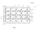
- Fig. 1 shows a steam reformer 1 with arranged in three parallel rows of reformer tubes 2. Parallel to the rows of reformer tubes, the burner 3 in four rows in the roof of Dampfreformergepuruses 4 are arranged. Opposite the combustion rows is a channel 5 for removing the burner exhaust gas below the bottom 6 of the reformer housing 4 is installed in each case. The upper limit, ie the cover 11 of the channel 5 also simultaneously forms part of the bottom 6 of the reformer housing 4. In Fig. 1 the openings for the passage of the burner exhaust gases in the covers are not shown. The arrows 7 indicate the flow direction of the burner exhaust gas. The burner exhaust gas, when it exits at the end of the duct 5, is taken over by an exhaust collection system (not shown in the drawing) which comprises a suction device.
- an exhaust collection system (not shown in the drawing) which comprises a suction device.
- Fig. 2 shows the steam reformer 1 seen from the front side.
- the arrows 8 represent the fuel gas supply to the burners 3.
- the flames of the burners 3a are directed vertically into the reformer housing 4.
- the arrows 9 represent the educt gas supply to the reformer tubes 2 and the arrows 10, the product gas discharge from the reformer tubes 2.
- Through the reformer bottom 6 passes through passages in the channel cover 11, symbolized here by a dashed line, the burner exhaust gas 7 into the exhaust ducts 5.
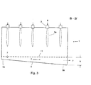
- Fig. 3 shows the steam reformer 1 seen from the longitudinal side.
- H the height of the channel 5 increases according to the invention from the channel beginning 5a to the channel end 5b.
- Fig. 4 corresponds to a section of Fig. 1 and shows a lying between two rows of reformer tubes 2 Brennerabgaskanal 6.
- the opening of the channel cover 11 is covered with a grid and the shape of the opening has a continuous over the entire channel length and thereby tapering in the flow direction spline.
- Fig. 5 also corresponds to a section Fig. 1 and also shows a burner exhaust duct 6 located between two rows of reformer tubes 2.
- the ceiling of the duct consists of a plurality of slabs 12 extending across the entire width of the duct and spaced at intervals from one another on the grate-covered duct ceiling. in such a way that the distances between the plates, and thus the openings in the duct ceiling, from the channel beginning towards the channel end, ie in the flow direction of the burner exhaust gases, become continuously smaller.
- the invention serves to improve the uniformity of the heating of a steam reformer. This increases the economy of the reformer operation.
- the invention is therefore industrially applicable.
Landscapes
- Chemical & Material Sciences (AREA)
- Chemical Kinetics & Catalysis (AREA)
- Organic Chemistry (AREA)
- Health & Medical Sciences (AREA)
- General Health & Medical Sciences (AREA)
- Engineering & Computer Science (AREA)
- Combustion & Propulsion (AREA)
- Inorganic Chemistry (AREA)
- Hydrogen, Water And Hydrids (AREA)
- Fuel Cell (AREA)
Abstract
Description
- Die Erfindung betrifft einen Dampfreformer, umfassend:
- einen Feuerraum, mit einem Boden, einer Decke und den Feuerraum abschließenden Seitenwänden,
- in mehreren Reihen angeordnete Katalysatorrohre, die den Boden und/oder die Decke des Feuerraums durchstoßen,
- in der Decke, dem Boden oder einer oder mehrerer Seitenwände des Feuerraums angeordnete Brenner zur Beheizung der Katalysatorrohre,
- unterhalb des Bodens oder oberhalb der Decke des Feuerraums verlaufende Zuleitungen jeweils für die Versorgung der Katalysatorrohre mit Eduktgas und der Brenner mit Luft und Brenngas,
- unterhalb des Bodens oder oberhalb der Decke des Feuerraums verlaufende Sammelleitungen für die Ableitung des Produktgases,
- unterhalb des Bodens oder oberhalb der Decke des Feuerraums verlaufende Kanäle zur Abfuhr der Brennerabgase aus dem Feuerraum, wobei die Decken der Kanäle jeweils vom Boden oder der Decke des Feuerraums gebildet werden, wobei die Kanäle längs und dabei zwischen den Reihen der Katalysatorrohre angeordnet sind und wobei die Decken der Kanäle Öffnungen für den Durchtritt der Abgase aufweisen.
- Die Erfindung betrifft weiterhin ein Verfahren zur katalytischen Umwandlung von kohlenwasserstoffhaltigem Gas mit Dampf in ein Wasserstoff und Kohlenoxide enthaltendes Synthesegas.
- Dampfreformer zur Umwandlung von gasförmigen Kohlenwasserstoffen mit Dampf in hauptsächlich aus Kohlenmonoxid und Wasserstoff bestehendes Synthesegas sind bekannt. Das Dampfreformierungsverfahren wird grundsätzlich, z. B. in Ullmann's Encyclopedia of Industrial Chemistry, Sixth Ed., Vol. 15, Kapitel "Gas Production", Kap. 2.2 beschrieben. Auf die verschiedenen, für dieses Verfahren bewährten Typen von Rohrreaktoren wird dabei in Kap. 2.2.3 desselben Kapitels eingegangen. Dort werden Rohrreaktoren gezeigt, bei denen die Brenner im Dach oder in den Seitenwänden des Reformergehäuses installiert sind. Dazu ist zu ergänzen, dass auch Varianten mit im Boden des Gehäuses installierten Brennern, mit vertikal nach oben, in das Gehäuse hinein gerichteten Flammen, möglich sind, wie es z. B. in der Offenlegungschrift
DE 2521683 A1 erwähnt ist. - Für die gleichmäßige Beheizung aller im Reformergehäuse befindlichen, mit einem Katalysatorfestbett gefüllten Reformerrohre ist die Ausgestaltung und die Anordnung der Kanäle zur Abfuhr der Brennerabgase aus dem Gehäuse sehr wichtig. Wie in Figur 6 des oben genannten Ullmann-Kapitels 2.2.3 gezeigt, besteht eine bewährte Auslegung der Reformer darin, die Brenner im Gehäusedach und die Abgassammelkanäle am Boden des Gehäuses anzuordnen. Dabei befinden sich die Brenner und die Kanäle, sich jeweils gegenüberliegend, zwischen den Reihen der Reformerrohre. Aus der Offenlegungsschrift
DE 102011120938 A1 ist auch die Möglichkeit bekannt, die Abgassammelkanäle direkt unter dem Boden des Reformergehäuses anzuordnen. Dabei bildet der Boden des Reformergehäuses gleichzeitig die Abdeckung der Kanäle. Durch Öffnungen in der Abdeckung tritt das Brennerabgas vom Reformergehäuse in die Abgassammelkanäle über. Die Enden der Kanäle sind dabei über eine Sammelleitung mit einer Vorrichtung zum Absaugen des Abgases, wie einem Gebläse oder einem Kamin, verbunden. Aufgrund des Strömungswiderstands, dem der Abgasstrom innerhalb der Kanäle jeweils unterliegt, führt zu einem Druckverlust vom Kanalanfang zum Kanalende. Ferner nimmt die abgesaugte Abgasmenge über die Länge der Kanäle kumulativ zu, da über zusätzliche Öffnungen in den Längsrichtungen der Kanäle zusätzliche Brennerabgase aus dem Reformergehäuse abgeführt werden. Hierdurch kommt es zu ungleichmäßigen, über die Kanallänge bzw. im Bodenbereich des Reformergehäuses verteilte Turbulenzen im Brennerabgas und damit zu einer ungleichmäßigen Beheizung der Reformerrohre. - Aufgabe der Erfindung ist es daher, einen Dampfreformer zur Verfügung zu stellen, bei dem die beschriebenen Nachteile bei der Absaugung der Brennerabgase vermieden werden. Diese Aufgabe wird durch einen Dampfreformer gemäß den Merkmalen des Anspruchs 1 gelöst:
- Dampfreformer, umfassend:
- einen Feuerraum, mit einem Boden, einer Decke und den Feuerraum abschließenden Seitenwänden,
- in mehreren Reihen angeordnete Katalysatorrohre, die den Boden und/oder die Decke des Feuerraums durchstoßen,
- in der Decke, dem Boden oder einer oder mehrerer Seitenwände des Feuerraums angeordnete Brenner zur Beheizung der Katalysatorrohre,
- unterhalb des Bodens oder oberhalb der Decke des Feuerraums verlaufende Zuleitungen jeweils für die Versorgung der Katalysatorrohre mit Eduktgas und der Brenner mit Luft und Brenngas,
- unterhalb des Bodens oder oberhalb der Decke des Feuerraums verlaufende Sammelleitungen für die Ableitung des Produktgases,
- unterhalb des Bodens oder oberhalb der Decke des Feuerraums verlaufende Kanäle zur Abfuhr der Brennerabgase aus dem Feuerraum, wobei die Decken bzw. Böden der Kanäle jeweils vom Boden oder der Decke des Feuerraums gebildet werden, wobei die Kanäle längs und dabei zwischen den Reihen der Katalysatorrohre angeordnet sind und wobei die Decken der Kanäle Öffnungen für den Durchtritt der Abgase aufweisen,
- Indem erfindungsgemäß die Strömungsgeschwindigkeit über die Länge des Kanals konstant gehalten wird, bleibt ebenso das Verhältnis zwischen dem dynamischen und dem statischen Anteil des Drucks, gemäß dem Energieerhaltungssatz nach Bernoulli, konstant. Würde dagegen die Strömungsgeschwindigkeit vom Kanalanfang zum Kanalanfang hin zunehmen, so würde durch diese Zunahme des dynamischen Druckanteils der statische Druckanteil sinken und damit die statische Druckdifferenz zwischen den Innenräumen des Reformergehäuses und des Kanals steigen. Das wiederum würde tendenziell zu einer stärkeren Absaugung von Brennerabgas in diesem Bereich der Kanäle führen, der mit einer Verkleinerung der Durchtrittsöffnungen zwischen Gehäuse und Kanal begegnet werden müsste.
- Weiterhin umfasst die Erfindung ein Verfahren zur katalytischen Umwandlung von kohlenwasserstoffhaltigem Gas mit Dampf in ein Wasserstoff und Kohlenoxide enthaltendes Synthesegas, umfassend die folgenden Verfahrensschritte:
- Bereitstellen eines kohlenwasserstoffhaltigen Gases und von Dampf,
- Erzeugen eines Eduktgases durch Vermischen des Gases und des Dampfs,
- Umwandeln des Eduktgases in ein Wasserstoff und Kohlenoxide umfassendes Synthesegas durch Umsetzen in einem Dampfreformer gemäß eines der Ansprüche 1 bis 6 unter Reformierungsbedingungen,
- Ausleiten des Synthesegases zur weiteren Behandlung außerhalb des Verfahrens.
- Unter Reformierungsbedingungen werden die dem Fachmann an sich geläufigen Betriebsbedingungen der Reformeranlage verstanden, die einen technisch und ökonomisch sinnvollen Umsetzungsgrad der Einsatzstoffe zu Synthesegaskomponenten gewährleisten. Ein hierfür gewählter Satz von Betriebsbedingungen wird auch als Betriebspunkt bezeichnet.
- Eine bevorzugte Ausgestaltung der Erfindung ist dadurch gekennzeichnet, dass die Kanäle ein keilförmiges, sich in Strömungsrichtung von ihrem Anfang zu ihrem Ende hin aufweitendes Längsprofil aufweisen. Diese Ausgestaltung trägt der über die Länge der Abgaskanäle kumulativ anwachsenden Abgasmenge Rechnung.
- Bevorzugt wird es weiterhin, wenn die Öffnungen in den Kanaldecken jeweils über die gesamte Kanallänge durchgehend sind und dabei ein sich in Strömungsrichtung verjüngendes Keilprofil aufweisen. Hierdurch vergrößert sich der Druckverlust über die Länge der Abgaskanäle beim Durchtritt der Brennerabgase vom Feuerraum in die Kanäle, so dass die Brennerabgase aus dem hinteren, der Absaugvorrichtung abgewandten Teil der Abgaskanäle leichter abgesaugt werden können.
- Die beiden vorgenannten bevorzugten Ausgestaltungen sind vorteilhaft kombinierbar, da auf diese Weise die Änderung des Kanalquerschnitts und die Änderung der Größe der Öffnungen in den Kanaldecken zwischen Reformergehäuse und Kanal kontinuierlich und ohne Sprünge erfolgen, was der Vergleichmäßigung der Abgasströmung des Brennerabgases aus dem Reformergehäuse zu Gute kommt. Einseitige mechanische Belastungen der Abgaskanäle oder des Feureraums, sowie die durch Turbulenzen verursachte ungleichmäßige Beheizung der Reformerrohre werden so reduziert.
- In einer weiteren bevorzugten Ausgestaltung der Erfindung sind die Öffnungen in den Kanaldecken durch Gitterroste abgedeckt. Auf diese Weise wird eine zusammenhängende Öffnung gebildet, die nicht durch geschlossene Stellen unterbrochen ist. Dies trägt positiv zu einer weiteren Vergleichmäßigung der Abgasströmung bei.
- Eine weitere bevorzugte Ausgestaltung der Erfindung ist dadurch gekennzeichnet, dass die Decken der Kanäle jeweils aus einer Vielzahl von über die gesamte Breite des Kanals verlaufende Platten bestehen, wobei Öffnungen in den Kanaldecken gebildet werden, indem die Platten in Abständen zueinander verlegt werden. Auf diese Weise wird die Breite der Kanalöffnung über die gesamte Kanallänge beibehalten. Hierdurch werden die Konstruktion und die Bauausführung der Kanäle vereinfacht. Die Größe der
- Durchtrittsöffnungen kann durch Austausch und/oder Verschieben der Platten auf einfache Weise verändert werden.
- Eine weitere bevorzugte Ausgestaltung der Erfindung ist dadurch gekennzeichnet, dass die Abstände der Platten zueinander in Strömungsrichtung des Abgases kontinuierlich kleiner werden. Da durch den Reibungswiderstand, den die Kanalwände auf die Gas-strömung ausüben der statische Druck im Kanal in Strömungsrichtung abnimmt, wird so der Abzug des Brennerabgases aus dem Reformergehäuse über die Kanallänge vergleichmäßigt.
- Weitere Merkmale, Vorteile und Anwendungsmöglichkeiten der Erfindung ergeben sich auch aus der nachfolgenden Beschreibung von Ausführungsbeispielen und den Zeichnungen. Dabei bilden alle beschriebenen und/oder bildlich dargestellten Merkmale für sich oder in beliebiger Kombination den Gegenstand der Erfindung, unabhängig von ihrer Zusammenfassung in den Ansprüchen oder deren Rückbeziehung.
- Anhand der Zeichnung soll eine beispielhafte Ausführung der Erfindung erläutert werden. Dabei zeigen:
- Fig. 1, C-C'
- eine Schnittzeichnung des Dampfreformers, von oben gesehen,
- Fig. 2, A-A',
- eine Schnittzeichnung des Dampfreformers, von der Stirnseite gesehen,
- Fig. 3, B-B',
- eine Schnittzeichnung des Dampfreformers, von der Längsseite gesehen,
- Fig. 4,
- einen Abgaskanal mit keilförmiger Öffnung zum Reformergehäuse,
- Fig. 5,
- einen Abgaskanal, dessen Öffnung zum Reformergehäuse mit Platten abgedeckt ist.
-
Fig. 1 zeigt einen Dampfreformer 1 mit in drei parallelen Reihen angeordneten Reformerrohren 2. Parallel zu den Reformerrohrreihen sind die Brenner 3 in vier Reihen im Dach des Dampfreformergehäuses 4 angeordnet. Den Brennreihen gegenüberliegend ist jeweils ein Kanal 5 zu Abfuhr des Brennerabgases unterhalb des Bodens 6 des Reformergehäuses 4 installiert. Die obere Begrenzung, d.h. die Abdeckung 11 des Kanals 5 bildet auch gleichzeitig einen Teil des Bodens 6 des Reformergehäuses 4. InFig. 1 sind die Öffnungen für den Durchtritt der Brennerabgase in den Abdeckungen nicht dargestellt. Die Pfeile 7 zeigen die Strömungsrichtung des Brennerabgases an. Das Brennerabgas wird, wenn es am Ende des Kanals 5 austritt, von einem nicht bildlich dargestellten Abgassammelsystem übernommen, das eine Absaugvorrichtung umfasst. -
Fig. 2 zeigt den Dampfreformer 1 von der Stirnseite aus gesehen. Die Pfeile 8 stellen die Brenngaszufuhr zu den Brennern 3 dar. Die Flammen der Brenner 3a sind senkrecht in das Reformergehäuse 4 hineingerichtet. Die Pfeile 9 stellen die Eduktgaszufuhr zu den Reformerrohren 2 und die Pfeile 10 die Produktgasabfuhr aus den Reformerrohren 2 dar. Durch den Reformerboden 6 tritt durch Durchlässe in der Kanalabdeckung 11, hier durch eine gestrichelte Linie symbolisiert, das Brennerabgas 7 in die Abgaskanäle 5 über. -
Fig. 3 zeigt den Dampfreformer 1 von der Längsseite aus gesehen. In dieser Figur ist skizziert, wie die Höhe H, und damit der Querschnitt, des Kanals 5 vom Kanalanfang 5a bis zum Kanalende 5b erfindungsgemäß zunimmt. -
Fig. 4 entspricht einem Ausschnitt ausFig. 1 und zeigt einen zwischen zwei Reihen von Reformerrohren 2 liegenden Brennerabgaskanal 6. Die Öffnung der Kanalabdeckung 11 ist dabei mit einem Gitterrost abgedeckt und die Form der Öffnung weist ein über die gesamte Kanallänge durchgehendes und sich dabei in Strömungsrichtung verjüngendes Keilprofil auf. -
Fig. 5 entspricht ebenfalls einem Ausschnitt ausFig. 1 und zeigt ebenfalls einen zwischen zwei Reihen von Reformerrohren 2 liegenden Brennerabgaskanal 6. In diesem Fall besteht die Decke des Kanals aus einer Vielzahl von über die gesamte Breite des Kanals verlaufenden Platten 12, die in Abständen zu einander auf der mit Gitterrost abgedeckten Kanaldecke verlegt sind, und zwar so, dass die Abstände zwischen den Platten, und damit die Öffnungen in der Kanaldecke, vom Kanalanfang zum Kanalende hin, also in Strömungsrichtung der Brennerabgase, kontinuierlich kleiner werden. - Die Erfindung dient dazu, die Gleichmäßigkeit der Beheizung eines Dampfreformers zu verbessern. Dadurch wird die Wirtschaftlichkeit des Reformerbetriebs erhöht. Die Erfindung ist daher gewerblich anwendbar.
-
- 1
- Dampfreformer
- 2
- Reformerrohr
- 3
- Brenner
- 4
- Reformergehäuse
- 5
- Abgaskanal zur Abfuhr von Brennerabgas
- 5a
- Kanalanfang des Abgaskanals
- 5b
- Kanalende des Abgaskanals
- 6
- Boden des Reformergehäuses
- 7
- Brennerabgase
- 8
- Brenngas
- 9
- Eduktgas
- 10
- Produktgas
- 11
- Gasdurchlässige Abdeckung für Abgaskanal, Teil des Reformergehäusebodens
- 12
- Platten zum örtlichen Abdecken von 11
Claims (7)
- Dampfreformer, umfassend:- einen Feuerraum, mit einem Boden, einer Decke und den Feuerraum abschließenden Seitenwänden,- in mehreren Reihen angeordnete Katalysatorrohre, die den Boden und/oder die Decke des Feuerraums durchstoßen,- in der Decke, dem Boden oder einer oder mehrerer Seitenwände des Feuerraums angeordnete Brenner zur Beheizung der Katalysatorrohre,- unterhalb des Bodens oder oberhalb der Decke des Feuerraums verlaufende Zuleitungen jeweils für die Versorgung der Katalysatorrohre mit Eduktgas und der Brenner mit Luft und Brenngas,- unterhalb des Bodens oder oberhalb der Decke des Feuerraums verlaufende Sammelleitungen für die Ableitung des Produktgases,- unterhalb des Bodens oder oberhalb der Decke des Feuerraums verlaufende Kanäle zur Abfuhr der Brennerabgase aus dem Feuerraum, wobei die Decken bzw. Böden der Kanäle jeweils vom Boden oder der Decke des Feuerraums gebildet werden, wobei die Kanäle längs und dabei zwischen den Reihen der Katalysatorrohre angeordnet sind und wobei die Decken der Kanäle Öffnungen für den Durchtritt der Abgase aufweisen, dadurch gekennzeichnet, dass
die Kanäle zur Abfuhr der Brennerabgase so ausgestaltet sind, dass die Strömungsgeschwindigkeit der Brennerabgase über die gesamte Länge der Kanäle, senkrecht zu den Katalysatorrohren gesehen, konstant ist. - Dampfreformer gemäß Anspruch 1, dadurch gekennzeichnet, dass die Kanäle ein keilförmiges, sich in Strömungsrichtung von ihrem Anfang zu ihrem Ende hin aufweitendes Längsprofil aufweisen.
- Dampfreformer gemäß Anspruch 1 oder 2, dadurch gekennzeichnet, dass die Öffnungen in den Kanaldecken durch Gitterroste abgedeckt sind.
- Dampfreformer gemäß eines der vorigen Ansprüche, dadurch gekennzeichnet, dass die Öffnungen in den Kanaldecken jeweils über die gesamte Kanallänge durchgehend sind und dabei ein sich in Strömungsrichtung verjüngendes Keilprofil aufweisen.
- Dampfreformer, gemäß eines der vorigen Ansprüche, dadurch gekennzeichnet, dass die Decken der Kanäle jeweils aus einer Vielzahl von über die gesamte Breite des Kanals verlaufende Platten bestehen, wobei Öffnungen in den Kanaldecken gebildet werden, indem die Platten in Abständen zu einander verlegt werden.
- Dampfreformer gemäß Anspruch 5, dadurch gekennzeichnet, dass die Öffnungen in den Kanaldecken in Strömungsrichtung kontinuierlich kleiner werden.
- Verfahren zur katalytischen Umwandlung von kohlenwasserstoffhaltigem Gas mit Dampf in ein Wasserstoff und Kohlenoxide enthaltendes Synthesegas, umfassend die folgenden Verfahrensschritte:- Bereitstellen eines kohlenwasserstoffhaltigen Gases und von Dampf,- Erzeugen eines Eduktgases durch Vermischen des Gases und des Dampfs,- Umwandeln des Eduktgases in ein Wasserstoff und Kohlenoxide umfassendes Synthesegas durch Umsetzen in einem Dampfreformer gemäß eines der Ansprüche 1 bis 6 unter Reformierungsbedingungen,- Ausleiten des Synthesegases zur weiteren Behandlung außerhalb des Verfahrens.
Priority Applications (6)
| Application Number | Priority Date | Filing Date | Title |
|---|---|---|---|
| EP15400044.2A EP3153465B1 (de) | 2015-10-05 | 2015-10-05 | Reformer zur erzeugung von synthesegas |
| DE102015117573.8A DE102015117573A1 (de) | 2015-10-05 | 2015-10-15 | Reformer zur Erzeugung von Synthesegas |
| US15/765,884 US10773230B2 (en) | 2015-10-05 | 2016-09-28 | Reformer for producing synthesis gas having improved burner waste gas flow |
| PCT/EP2016/025104 WO2017059962A1 (en) | 2015-10-05 | 2016-09-28 | Reformer for producing synthesis gas |
| CN201610888418.XA CN106938838B (zh) | 2015-10-05 | 2016-09-30 | 用于生产合成气体的重整炉 |
| CN201621114395.9U CN206767645U (zh) | 2015-10-05 | 2016-09-30 | 用于生产合成气体的重整炉 |
Applications Claiming Priority (1)
| Application Number | Priority Date | Filing Date | Title |
|---|---|---|---|
| EP15400044.2A EP3153465B1 (de) | 2015-10-05 | 2015-10-05 | Reformer zur erzeugung von synthesegas |
Publications (2)
| Publication Number | Publication Date |
|---|---|
| EP3153465A1 true EP3153465A1 (de) | 2017-04-12 |
| EP3153465B1 EP3153465B1 (de) | 2020-01-01 |
Family
ID=54541004
Family Applications (1)
| Application Number | Title | Priority Date | Filing Date |
|---|---|---|---|
| EP15400044.2A Active EP3153465B1 (de) | 2015-10-05 | 2015-10-05 | Reformer zur erzeugung von synthesegas |
Country Status (5)
| Country | Link |
|---|---|
| US (1) | US10773230B2 (de) |
| EP (1) | EP3153465B1 (de) |
| CN (2) | CN206767645U (de) |
| DE (1) | DE102015117573A1 (de) |
| WO (1) | WO2017059962A1 (de) |
Cited By (1)
| Publication number | Priority date | Publication date | Assignee | Title |
|---|---|---|---|---|
| EP3821973A1 (de) | 2019-11-13 | 2021-05-19 | L'air Liquide, Société Anonyme Pour L'Étude Et L'exploitation Des Procédés Georges Claude | Reformerofen zur durchführung eines endothermen prozesses |
Families Citing this family (1)
| Publication number | Priority date | Publication date | Assignee | Title |
|---|---|---|---|---|
| EP3153465B1 (de) * | 2015-10-05 | 2020-01-01 | L'Air Liquide Société Anonyme pour l'Etude et l'Exploitation des Procédés Georges Claude | Reformer zur erzeugung von synthesegas |
Citations (7)
| Publication number | Priority date | Publication date | Assignee | Title |
|---|---|---|---|---|
| DE2521683A1 (de) | 1974-05-22 | 1975-12-04 | Lummus Co | Heizvorrichtung |
| DE19512219C1 (de) * | 1995-03-22 | 1996-04-04 | Mannesmann Ag | Anlage zur indirekten Übertragung von Wärme auf ein Prozeßmedium |
| EP0814055A2 (de) * | 1996-06-19 | 1997-12-29 | Mitsubishi Heavy Industries, Ltd. | Verbrennungsabgasleitung für Dampfreformer |
| US20070234974A1 (en) * | 2006-04-10 | 2007-10-11 | The Cust-O-Fab Companies, Llc | Fired heater and flue gas tunnel therefor |
| WO2010149361A2 (de) * | 2009-06-24 | 2010-12-29 | Uhde Gmbh | Primärreformer mit variablem rauchgasstrom |
| DE102011120938A1 (de) | 2011-12-14 | 2013-06-20 | Thyssenkrupp Uhde Gmbh | Transportabler Reformer |
| EP2708812A1 (de) * | 2012-09-13 | 2014-03-19 | L'AIR LIQUIDE, Société Anonyme pour l'Etude et l'Exploitation des Procédés Georges Claude | Verfahren und Vorrichtung für endotherme Reaktionen |
Family Cites Families (27)
| Publication number | Priority date | Publication date | Assignee | Title |
|---|---|---|---|---|
| US2028326A (en) * | 1931-01-23 | 1936-01-21 | Standard Oil Dev Co | Apparatus for the production of hydrogen |
| US3334971A (en) * | 1964-08-18 | 1967-08-08 | Chemical Construction Corp | Catalytically reforming hydrocarbon and steam mixtures |
| US3424695A (en) * | 1965-09-28 | 1969-01-28 | Peter Von Wiesenthal | Improving reformer-furnace performance by using gas-turbine exhaust |
| US4198385A (en) * | 1976-09-07 | 1980-04-15 | Waagner-Biro Aktiengesellschaft | Reduction of sodium sulfate to sodium sulfide |
| US4108119A (en) * | 1977-01-19 | 1978-08-22 | Mcwhorter Edward Milton | Bottom cycle manifold for four-stroke internal combustion engines |
| US6134879A (en) * | 1989-12-21 | 2000-10-24 | United Technologies Corporation | Suppression system for a gas turbine engine |
| US5417731A (en) * | 1993-09-14 | 1995-05-23 | Owens-Brockway Glass Container, Inc. | Method of heating a charge, including injecting secondary oxidant into the output port |
| AU687930B2 (en) * | 1993-12-23 | 1998-03-05 | John Stuart Fleming | Flammable fluid fuelled heater |
| US6303092B1 (en) * | 1995-04-10 | 2001-10-16 | Air Products And Chemicals, Inc. | Process for operating equilibrium controlled reactions |
| JP2001249065A (ja) * | 1999-12-28 | 2001-09-14 | Ono Sokki Co Ltd | 排出ガス希釈装置 |
| JP4815668B2 (ja) * | 2000-05-15 | 2011-11-16 | トヨタ自動車株式会社 | 水素生成装置 |
| ES2248207T3 (es) * | 2000-09-20 | 2006-03-16 | Air Products And Chemicals, Inc. | Dispositivo y procedimiento para la reformacion de hidrocarburos. |
| JP2003288934A (ja) * | 2002-01-23 | 2003-10-10 | Nissan Motor Co Ltd | 燃料電池用燃料改質装置 |
| US6844637B1 (en) * | 2003-08-13 | 2005-01-18 | Curtiss-Wright Electro-Mechanical Corporation | Rotor assembly end turn cooling system and method |
| US7833009B2 (en) * | 2004-09-10 | 2010-11-16 | Air Products And Chemicals, Inc. | Oxidant injection method |
| DE102005020943A1 (de) * | 2005-05-04 | 2006-11-09 | Linde Ag | Verfahren und Reaktor zur Durchführung endothermer katalytischer Reaktionen |
| US7504048B2 (en) * | 2005-06-14 | 2009-03-17 | Air Products And Chemicals, Inc. | Axial convective reformer |
| US7686611B2 (en) * | 2005-11-03 | 2010-03-30 | Air Products And Chemicals, Inc. | Flame straightening in a furnace |
| CN100439697C (zh) * | 2007-01-19 | 2008-12-03 | 合肥工业大学 | 具有燃料重整机构的柴油机排放系统 |
| FR2914396A1 (fr) * | 2007-03-30 | 2008-10-03 | Inst Francais Du Petrole | Nouveau four de vaporeformage utilisant des bruleurs poreux |
| US8545213B2 (en) * | 2010-03-09 | 2013-10-01 | Air Products And Chemicals, Inc. | Reformer and method of operating the reformer |
| MY158746A (en) * | 2010-10-22 | 2016-11-15 | Lanzatech New Zealand Ltd | Methods and systems for the production of hydrocarbon products |
| WO2013002752A1 (en) * | 2011-06-27 | 2013-01-03 | Air Products And Chemicals, Inc. | Method of operating a catalytic steam-hydrocarbon reformer |
| US20130074515A1 (en) * | 2011-09-23 | 2013-03-28 | General Electric Company | Gas turbine engine system and method of providing a fuel supplied to one or more combustors in a gas turbine engine system |
| US9272905B2 (en) * | 2014-02-27 | 2016-03-01 | Honeywell International, Inc. | Method for optimizing down fired reforming furnaces |
| US9958211B2 (en) * | 2015-03-12 | 2018-05-01 | Bayotech, Inc. | Nested-flow heat exchangers and chemical reactors |
| EP3153465B1 (de) * | 2015-10-05 | 2020-01-01 | L'Air Liquide Société Anonyme pour l'Etude et l'Exploitation des Procédés Georges Claude | Reformer zur erzeugung von synthesegas |
-
2015
- 2015-10-05 EP EP15400044.2A patent/EP3153465B1/de active Active
- 2015-10-15 DE DE102015117573.8A patent/DE102015117573A1/de not_active Withdrawn
-
2016
- 2016-09-28 WO PCT/EP2016/025104 patent/WO2017059962A1/en not_active Ceased
- 2016-09-28 US US15/765,884 patent/US10773230B2/en active Active
- 2016-09-30 CN CN201621114395.9U patent/CN206767645U/zh not_active Withdrawn - After Issue
- 2016-09-30 CN CN201610888418.XA patent/CN106938838B/zh not_active Expired - Fee Related
Patent Citations (8)
| Publication number | Priority date | Publication date | Assignee | Title |
|---|---|---|---|---|
| DE2521683A1 (de) | 1974-05-22 | 1975-12-04 | Lummus Co | Heizvorrichtung |
| DE19512219C1 (de) * | 1995-03-22 | 1996-04-04 | Mannesmann Ag | Anlage zur indirekten Übertragung von Wärme auf ein Prozeßmedium |
| EP0814055A2 (de) * | 1996-06-19 | 1997-12-29 | Mitsubishi Heavy Industries, Ltd. | Verbrennungsabgasleitung für Dampfreformer |
| US20070234974A1 (en) * | 2006-04-10 | 2007-10-11 | The Cust-O-Fab Companies, Llc | Fired heater and flue gas tunnel therefor |
| WO2010149361A2 (de) * | 2009-06-24 | 2010-12-29 | Uhde Gmbh | Primärreformer mit variablem rauchgasstrom |
| DE102011120938A1 (de) | 2011-12-14 | 2013-06-20 | Thyssenkrupp Uhde Gmbh | Transportabler Reformer |
| WO2013087194A1 (de) * | 2011-12-14 | 2013-06-20 | Thyssenkrupp Uhde Gmbh | Transportabler reformer |
| EP2708812A1 (de) * | 2012-09-13 | 2014-03-19 | L'AIR LIQUIDE, Société Anonyme pour l'Etude et l'Exploitation des Procédés Georges Claude | Verfahren und Vorrichtung für endotherme Reaktionen |
Non-Patent Citations (1)
| Title |
|---|
| "Ullmann's Encyclopedia of Industrial Chemistry", vol. 15, article "Gas Production" |
Cited By (2)
| Publication number | Priority date | Publication date | Assignee | Title |
|---|---|---|---|---|
| EP3821973A1 (de) | 2019-11-13 | 2021-05-19 | L'air Liquide, Société Anonyme Pour L'Étude Et L'exploitation Des Procédés Georges Claude | Reformerofen zur durchführung eines endothermen prozesses |
| US11906247B2 (en) | 2019-11-13 | 2024-02-20 | L'Air Liquide, Société Anonyme pour l'Etude et l'Expoitation des Procédés Georges Claude | Reformer furnace for performing an endothermic process |
Also Published As
| Publication number | Publication date |
|---|---|
| CN106938838B (zh) | 2021-12-14 |
| US10773230B2 (en) | 2020-09-15 |
| CN106938838A (zh) | 2017-07-11 |
| DE102015117573A1 (de) | 2017-04-06 |
| WO2017059962A1 (en) | 2017-04-13 |
| US20180296998A1 (en) | 2018-10-18 |
| EP3153465B1 (de) | 2020-01-01 |
| CN206767645U (zh) | 2017-12-19 |
Similar Documents
| Publication | Publication Date | Title |
|---|---|---|
| WO2006117136A1 (de) | Verfahren und reaktor zur durchführung endothermer katalytischer reaktionen | |
| EP2101900A1 (de) | Reaktor zur durchführung einer kontinuierlichen oxidehydrierung sowie verfahren | |
| DE2362132C2 (de) | Einrichtung zur thermischen Behandlung von feinkörnigem Gut mit mehreren einem Wärmetauschersystem zugeordneten Zusatzbrenneinrichtungen | |
| EP2205348A1 (de) | Horizontaler reaktor zur umsetzung eines fluiden eduktstromes mit einem fluiden oxidatorstrom in gegenwart eines feststoffkatalysators | |
| EP3153465A1 (de) | Reformer zur erzeugung von synthesegas | |
| EP0427828B1 (de) | Beheizungsräume in koksöfen und verfahren zur beheizung | |
| EP3068529A1 (de) | Verfahren und vorrichtung zur dampfreformierung sowie zur dampfspaltung von kohlenwasserstoffen | |
| DE3701161A1 (de) | Ofen | |
| DE2203420A1 (de) | Verfahren und Einrichtung zum Erhitzen eines stroemenden Mediums | |
| DE1767980A1 (de) | Rohrofen | |
| DE10333854A1 (de) | Röhrenspaltofen | |
| DE202015105493U1 (de) | Reformer zur Erzeugung von Synthesegas | |
| EP0815406B1 (de) | Anlage zur indirekten übertragung von wärme auf ein prozessmedium | |
| DE7515596U (de) | Heizvorrichtung | |
| EP3153464A1 (de) | Dampfreformer zur erzeugung von synthesegas | |
| DE102014018376A1 (de) | Verfahren und Vorrichtung zur Einleitung reaktiver Gase in einen Reaktionsraum | |
| EP3821973A1 (de) | Reformerofen zur durchführung eines endothermen prozesses | |
| DE202015105494U1 (de) | Dampfreformer zur Erzeugung von Synthesegas | |
| EP3243027B1 (de) | Feuerfeste wand, insbesondere für einen verbrennungsofen | |
| DE69805468T2 (de) | Vorrichtung und Verfahren zur Steuerung von Gasströmen in einer Destillationsanlage | |
| DE102015121037A1 (de) | Vorrichtung zur Sauerstoffverteilung in einem Oxidationsreaktor, Oxidationsreaktor und Anlage mit einer solchen Vorrichtung und Betriebsverfahren | |
| EP3838397A1 (de) | Reformerofen | |
| DE3111476A1 (de) | "batterieweise angeordneter kammerofen zur erzeugungvon koks und gas" | |
| EP0369556A2 (de) | Verfahren zur indirekten Erwärmung eines Prozessgasstroms in einem Reaktionsraum für eine endotherme Reaktion und Vorrichtung zu dessen Durchführung | |
| DE102014004091A1 (de) | Dampfreformer |
Legal Events
| Date | Code | Title | Description |
|---|---|---|---|
| PUAI | Public reference made under article 153(3) epc to a published international application that has entered the european phase |
Free format text: ORIGINAL CODE: 0009012 |
|
| STAA | Information on the status of an ep patent application or granted ep patent |
Free format text: STATUS: THE APPLICATION HAS BEEN PUBLISHED |
|
| AK | Designated contracting states |
Kind code of ref document: A1 Designated state(s): AL AT BE BG CH CY CZ DE DK EE ES FI FR GB GR HR HU IE IS IT LI LT LU LV MC MK MT NL NO PL PT RO RS SE SI SK SM TR |
|
| AX | Request for extension of the european patent |
Extension state: BA ME |
|
| STAA | Information on the status of an ep patent application or granted ep patent |
Free format text: STATUS: REQUEST FOR EXAMINATION WAS MADE |
|
| 17P | Request for examination filed |
Effective date: 20170608 |
|
| RBV | Designated contracting states (corrected) |
Designated state(s): AL AT BE BG CH CY CZ DE DK EE ES FI FR GB GR HR HU IE IS IT LI LT LU LV MC MK MT NL NO PL PT RO RS SE SI SK SM TR |
|
| STAA | Information on the status of an ep patent application or granted ep patent |
Free format text: STATUS: EXAMINATION IS IN PROGRESS |
|
| 17Q | First examination report despatched |
Effective date: 20190226 |
|
| RIC1 | Information provided on ipc code assigned before grant |
Ipc: B01J 8/06 20060101ALI20190528BHEP Ipc: C01B 3/38 20060101AFI20190528BHEP |
|
| GRAP | Despatch of communication of intention to grant a patent |
Free format text: ORIGINAL CODE: EPIDOSNIGR1 |
|
| STAA | Information on the status of an ep patent application or granted ep patent |
Free format text: STATUS: GRANT OF PATENT IS INTENDED |
|
| INTG | Intention to grant announced |
Effective date: 20190816 |
|
| GRAS | Grant fee paid |
Free format text: ORIGINAL CODE: EPIDOSNIGR3 |
|
| GRAA | (expected) grant |
Free format text: ORIGINAL CODE: 0009210 |
|
| STAA | Information on the status of an ep patent application or granted ep patent |
Free format text: STATUS: THE PATENT HAS BEEN GRANTED |
|
| AK | Designated contracting states |
Kind code of ref document: B1 Designated state(s): AL AT BE BG CH CY CZ DE DK EE ES FI FR GB GR HR HU IE IS IT LI LT LU LV MC MK MT NL NO PL PT RO RS SE SI SK SM TR |
|
| REG | Reference to a national code |
Ref country code: GB Ref legal event code: FG4D Free format text: NOT ENGLISH |
|
| REG | Reference to a national code |
Ref country code: CH Ref legal event code: EP Ref country code: AT Ref legal event code: REF Ref document number: 1219576 Country of ref document: AT Kind code of ref document: T Effective date: 20200115 |
|
| REG | Reference to a national code |
Ref country code: DE Ref legal event code: R096 Ref document number: 502015011381 Country of ref document: DE |
|
| REG | Reference to a national code |
Ref country code: IE Ref legal event code: FG4D Free format text: LANGUAGE OF EP DOCUMENT: GERMAN |
|
| REG | Reference to a national code |
Ref country code: NL Ref legal event code: FP |
|
| REG | Reference to a national code |
Ref country code: LT Ref legal event code: MG4D |
|
| PG25 | Lapsed in a contracting state [announced via postgrant information from national office to epo] |
Ref country code: CZ Free format text: LAPSE BECAUSE OF FAILURE TO SUBMIT A TRANSLATION OF THE DESCRIPTION OR TO PAY THE FEE WITHIN THE PRESCRIBED TIME-LIMIT Effective date: 20200101 Ref country code: LT Free format text: LAPSE BECAUSE OF FAILURE TO SUBMIT A TRANSLATION OF THE DESCRIPTION OR TO PAY THE FEE WITHIN THE PRESCRIBED TIME-LIMIT Effective date: 20200101 Ref country code: PT Free format text: LAPSE BECAUSE OF FAILURE TO SUBMIT A TRANSLATION OF THE DESCRIPTION OR TO PAY THE FEE WITHIN THE PRESCRIBED TIME-LIMIT Effective date: 20200527 Ref country code: RS Free format text: LAPSE BECAUSE OF FAILURE TO SUBMIT A TRANSLATION OF THE DESCRIPTION OR TO PAY THE FEE WITHIN THE PRESCRIBED TIME-LIMIT Effective date: 20200101 Ref country code: FI Free format text: LAPSE BECAUSE OF FAILURE TO SUBMIT A TRANSLATION OF THE DESCRIPTION OR TO PAY THE FEE WITHIN THE PRESCRIBED TIME-LIMIT Effective date: 20200101 Ref country code: NO Free format text: LAPSE BECAUSE OF FAILURE TO SUBMIT A TRANSLATION OF THE DESCRIPTION OR TO PAY THE FEE WITHIN THE PRESCRIBED TIME-LIMIT Effective date: 20200401 |
|
| PG25 | Lapsed in a contracting state [announced via postgrant information from national office to epo] |
Ref country code: IS Free format text: LAPSE BECAUSE OF FAILURE TO SUBMIT A TRANSLATION OF THE DESCRIPTION OR TO PAY THE FEE WITHIN THE PRESCRIBED TIME-LIMIT Effective date: 20200501 Ref country code: BG Free format text: LAPSE BECAUSE OF FAILURE TO SUBMIT A TRANSLATION OF THE DESCRIPTION OR TO PAY THE FEE WITHIN THE PRESCRIBED TIME-LIMIT Effective date: 20200401 Ref country code: GR Free format text: LAPSE BECAUSE OF FAILURE TO SUBMIT A TRANSLATION OF THE DESCRIPTION OR TO PAY THE FEE WITHIN THE PRESCRIBED TIME-LIMIT Effective date: 20200402 Ref country code: LV Free format text: LAPSE BECAUSE OF FAILURE TO SUBMIT A TRANSLATION OF THE DESCRIPTION OR TO PAY THE FEE WITHIN THE PRESCRIBED TIME-LIMIT Effective date: 20200101 Ref country code: SE Free format text: LAPSE BECAUSE OF FAILURE TO SUBMIT A TRANSLATION OF THE DESCRIPTION OR TO PAY THE FEE WITHIN THE PRESCRIBED TIME-LIMIT Effective date: 20200101 Ref country code: HR Free format text: LAPSE BECAUSE OF FAILURE TO SUBMIT A TRANSLATION OF THE DESCRIPTION OR TO PAY THE FEE WITHIN THE PRESCRIBED TIME-LIMIT Effective date: 20200101 |
|
| REG | Reference to a national code |
Ref country code: DE Ref legal event code: R097 Ref document number: 502015011381 Country of ref document: DE |
|
| PG25 | Lapsed in a contracting state [announced via postgrant information from national office to epo] |
Ref country code: DK Free format text: LAPSE BECAUSE OF FAILURE TO SUBMIT A TRANSLATION OF THE DESCRIPTION OR TO PAY THE FEE WITHIN THE PRESCRIBED TIME-LIMIT Effective date: 20200101 Ref country code: ES Free format text: LAPSE BECAUSE OF FAILURE TO SUBMIT A TRANSLATION OF THE DESCRIPTION OR TO PAY THE FEE WITHIN THE PRESCRIBED TIME-LIMIT Effective date: 20200101 Ref country code: EE Free format text: LAPSE BECAUSE OF FAILURE TO SUBMIT A TRANSLATION OF THE DESCRIPTION OR TO PAY THE FEE WITHIN THE PRESCRIBED TIME-LIMIT Effective date: 20200101 Ref country code: SM Free format text: LAPSE BECAUSE OF FAILURE TO SUBMIT A TRANSLATION OF THE DESCRIPTION OR TO PAY THE FEE WITHIN THE PRESCRIBED TIME-LIMIT Effective date: 20200101 Ref country code: RO Free format text: LAPSE BECAUSE OF FAILURE TO SUBMIT A TRANSLATION OF THE DESCRIPTION OR TO PAY THE FEE WITHIN THE PRESCRIBED TIME-LIMIT Effective date: 20200101 Ref country code: SK Free format text: LAPSE BECAUSE OF FAILURE TO SUBMIT A TRANSLATION OF THE DESCRIPTION OR TO PAY THE FEE WITHIN THE PRESCRIBED TIME-LIMIT Effective date: 20200101 |
|
| PLBE | No opposition filed within time limit |
Free format text: ORIGINAL CODE: 0009261 |
|
| STAA | Information on the status of an ep patent application or granted ep patent |
Free format text: STATUS: NO OPPOSITION FILED WITHIN TIME LIMIT |
|
| 26N | No opposition filed |
Effective date: 20201002 |
|
| PG25 | Lapsed in a contracting state [announced via postgrant information from national office to epo] |
Ref country code: PL Free format text: LAPSE BECAUSE OF FAILURE TO SUBMIT A TRANSLATION OF THE DESCRIPTION OR TO PAY THE FEE WITHIN THE PRESCRIBED TIME-LIMIT Effective date: 20200101 Ref country code: SI Free format text: LAPSE BECAUSE OF FAILURE TO SUBMIT A TRANSLATION OF THE DESCRIPTION OR TO PAY THE FEE WITHIN THE PRESCRIBED TIME-LIMIT Effective date: 20200101 |
|
| REG | Reference to a national code |
Ref country code: CH Ref legal event code: PL |
|
| PG25 | Lapsed in a contracting state [announced via postgrant information from national office to epo] |
Ref country code: LU Free format text: LAPSE BECAUSE OF NON-PAYMENT OF DUE FEES Effective date: 20201005 Ref country code: MC Free format text: LAPSE BECAUSE OF FAILURE TO SUBMIT A TRANSLATION OF THE DESCRIPTION OR TO PAY THE FEE WITHIN THE PRESCRIBED TIME-LIMIT Effective date: 20200101 |
|
| PG25 | Lapsed in a contracting state [announced via postgrant information from national office to epo] |
Ref country code: CH Free format text: LAPSE BECAUSE OF NON-PAYMENT OF DUE FEES Effective date: 20201031 Ref country code: LI Free format text: LAPSE BECAUSE OF NON-PAYMENT OF DUE FEES Effective date: 20201031 |
|
| PG25 | Lapsed in a contracting state [announced via postgrant information from national office to epo] |
Ref country code: IE Free format text: LAPSE BECAUSE OF NON-PAYMENT OF DUE FEES Effective date: 20201005 |
|
| REG | Reference to a national code |
Ref country code: AT Ref legal event code: MM01 Ref document number: 1219576 Country of ref document: AT Kind code of ref document: T Effective date: 20201005 |
|
| PG25 | Lapsed in a contracting state [announced via postgrant information from national office to epo] |
Ref country code: AT Free format text: LAPSE BECAUSE OF NON-PAYMENT OF DUE FEES Effective date: 20201005 |
|
| PG25 | Lapsed in a contracting state [announced via postgrant information from national office to epo] |
Ref country code: TR Free format text: LAPSE BECAUSE OF FAILURE TO SUBMIT A TRANSLATION OF THE DESCRIPTION OR TO PAY THE FEE WITHIN THE PRESCRIBED TIME-LIMIT Effective date: 20200101 Ref country code: MT Free format text: LAPSE BECAUSE OF FAILURE TO SUBMIT A TRANSLATION OF THE DESCRIPTION OR TO PAY THE FEE WITHIN THE PRESCRIBED TIME-LIMIT Effective date: 20200101 Ref country code: CY Free format text: LAPSE BECAUSE OF FAILURE TO SUBMIT A TRANSLATION OF THE DESCRIPTION OR TO PAY THE FEE WITHIN THE PRESCRIBED TIME-LIMIT Effective date: 20200101 |
|
| PG25 | Lapsed in a contracting state [announced via postgrant information from national office to epo] |
Ref country code: MK Free format text: LAPSE BECAUSE OF FAILURE TO SUBMIT A TRANSLATION OF THE DESCRIPTION OR TO PAY THE FEE WITHIN THE PRESCRIBED TIME-LIMIT Effective date: 20200101 Ref country code: AL Free format text: LAPSE BECAUSE OF FAILURE TO SUBMIT A TRANSLATION OF THE DESCRIPTION OR TO PAY THE FEE WITHIN THE PRESCRIBED TIME-LIMIT Effective date: 20200101 |
|
| P01 | Opt-out of the competence of the unified patent court (upc) registered |
Effective date: 20230518 |
|
| PGFP | Annual fee paid to national office [announced via postgrant information from national office to epo] |
Ref country code: IT Payment date: 20231020 Year of fee payment: 9 Ref country code: FR Payment date: 20231026 Year of fee payment: 9 |
|
| PG25 | Lapsed in a contracting state [announced via postgrant information from national office to epo] |
Ref country code: FR Free format text: LAPSE BECAUSE OF NON-PAYMENT OF DUE FEES Effective date: 20241031 |
|
| PG25 | Lapsed in a contracting state [announced via postgrant information from national office to epo] |
Ref country code: IT Free format text: LAPSE BECAUSE OF NON-PAYMENT OF DUE FEES Effective date: 20241005 |
|
| PGFP | Annual fee paid to national office [announced via postgrant information from national office to epo] |
Ref country code: NL Payment date: 20251021 Year of fee payment: 11 |
|
| PGFP | Annual fee paid to national office [announced via postgrant information from national office to epo] |
Ref country code: DE Payment date: 20251021 Year of fee payment: 11 |
|
| PGFP | Annual fee paid to national office [announced via postgrant information from national office to epo] |
Ref country code: GB Payment date: 20251022 Year of fee payment: 11 |
|
| PGFP | Annual fee paid to national office [announced via postgrant information from national office to epo] |
Ref country code: BE Payment date: 20251021 Year of fee payment: 11 |