EP3159588B1 - Procédé de commande d'un actionneur de soupape et dispositif de commande d'un actionneur de soupape - Google Patents
Procédé de commande d'un actionneur de soupape et dispositif de commande d'un actionneur de soupape Download PDFInfo
- Publication number
- EP3159588B1 EP3159588B1 EP15191197.1A EP15191197A EP3159588B1 EP 3159588 B1 EP3159588 B1 EP 3159588B1 EP 15191197 A EP15191197 A EP 15191197A EP 3159588 B1 EP3159588 B1 EP 3159588B1
- Authority
- EP
- European Patent Office
- Prior art keywords
- valve actuator
- control device
- valve
- signal transmitting
- actuator control
- Prior art date
- Legal status (The legal status is an assumption and is not a legal conclusion. Google has not performed a legal analysis and makes no representation as to the accuracy of the status listed.)
- Active
Links
Images


Classifications
-
- G—PHYSICS
- G05—CONTROLLING; REGULATING
- G05D—SYSTEMS FOR CONTROLLING OR REGULATING NON-ELECTRIC VARIABLES
- G05D7/00—Control of flow
- G05D7/06—Control of flow characterised by the use of electric means
- G05D7/0617—Control of flow characterised by the use of electric means specially adapted for fluid materials
-
- F—MECHANICAL ENGINEERING; LIGHTING; HEATING; WEAPONS; BLASTING
- F16—ENGINEERING ELEMENTS AND UNITS; GENERAL MEASURES FOR PRODUCING AND MAINTAINING EFFECTIVE FUNCTIONING OF MACHINES OR INSTALLATIONS; THERMAL INSULATION IN GENERAL
- F16K—VALVES; TAPS; COCKS; ACTUATING-FLOATS; DEVICES FOR VENTING OR AERATING
- F16K37/00—Special means in or on valves or other cut-off apparatus for indicating or recording operation thereof, or for enabling an alarm to be given
- F16K37/0025—Electrical or magnetic means
-
- F—MECHANICAL ENGINEERING; LIGHTING; HEATING; WEAPONS; BLASTING
- F16—ENGINEERING ELEMENTS AND UNITS; GENERAL MEASURES FOR PRODUCING AND MAINTAINING EFFECTIVE FUNCTIONING OF MACHINES OR INSTALLATIONS; THERMAL INSULATION IN GENERAL
- F16K—VALVES; TAPS; COCKS; ACTUATING-FLOATS; DEVICES FOR VENTING OR AERATING
- F16K31/00—Actuating devices; Operating means; Releasing devices
- F16K31/02—Actuating devices; Operating means; Releasing devices electric; magnetic
- F16K31/04—Actuating devices; Operating means; Releasing devices electric; magnetic using a motor
-
- F—MECHANICAL ENGINEERING; LIGHTING; HEATING; WEAPONS; BLASTING
- F16—ENGINEERING ELEMENTS AND UNITS; GENERAL MEASURES FOR PRODUCING AND MAINTAINING EFFECTIVE FUNCTIONING OF MACHINES OR INSTALLATIONS; THERMAL INSULATION IN GENERAL
- F16K—VALVES; TAPS; COCKS; ACTUATING-FLOATS; DEVICES FOR VENTING OR AERATING
- F16K37/00—Special means in or on valves or other cut-off apparatus for indicating or recording operation thereof, or for enabling an alarm to be given
- F16K37/0075—For recording or indicating the functioning of a valve in combination with test equipment
Definitions
- the present invention relates to a method for controlling a valve actuator, a valve actuator control device and a valve actuator assembly, more specifically it relates to an external and portable valve actuator control device.
- Fluid distribution systems for e.g. heating, cooling and water supply are designed to feed a fluid from a source to a consumption point.
- Each consumption point typically has a calculated and designed flow or differential pressure requirement.
- the flow requirement is often variable over time and can change with factors like seasonality (e.g. summer or winter), that changes the load from the consumption points, temperature changes of the system fluid, changes in consumption of the system fluid (e.g. for drinking water).
- Control valves e.g. sliding stem valves, rotary valves, etc.
- actuators e.g. electric or pneumatic
- actuators are provided with manual means of operation, often in the form of a handwheel which allows local operators to manually adjust the flow rate.
- most conventional actuators are provided with a set of jumpers or dipswitches in order to control and to configure operating parameters of the actuator.
- actuators are rather limited in their operational control, and it is often a very cumbersome task for a local operator to manage sites where there are large amounts of actuators.
- Some valve actuators are able to connect to a larger grid having a control desk or a common node from which the plurality of valve actuators may be controlled.
- HVAC heating, ventilation and air conditioning
- the valve actuator itself is preferably arranged to operate a control valve in a valve actuator assembly, e.g. operating in terms of adjusting a variable opening by moving a valve closing member by means of an electric motor.
- the control signals that are transmitted from the valve actuator control device via the signal transmitting wire may for example be signals in order to control an electrical motor within the valve actuator to adjust the stroke (position of the valve closing member).
- the control signals may also be signals for altering or uploading a set of operating parameters which may be stored in a control unit or memory unit comprised by the valve actuator. The valve actuator may then operate according to these operating parameters in an automated manner.
- valve actuator control device (may simply be referred to as control device in the following) is arranged with an energy storage unit capable of supplying operating power both to the control device itself and also to the valve actuator.
- Supplying operating power in this context may be interpreted as supplying enough energy to power an internal processing unit of the valve actuator, in order to perform diagnostic tests or configure operating parameters.
- supplying operating power may also be interpreted as supplying enough energy to power the electric motor within the valve actuator; in order to adjust the stroke, perform self-tests, calibration, etc.; or it may be interpreted as a combination of both.
- the operating power to the valve actuator may be supplied via the signal transmitting wire.
- valve actuator when the valve actuator is disconnected from the grid and the local operator can simply connect the valve actuator control device to the valve actuator and adjust the stroke e.g. with the push of a button (or a touch-sensitive area, a joystick, etc.), instead of being forced to adjust the stroke manually by turning a hand wheel. Also since the operating power (in the form of electricity) is supplied via the signal transmitting wire there is no need for a plurality of wired connections between the valve actuator and the valve actuator control device.
- the operating power in the form of electricity
- valve actuators can be facilitated since this now can be done by connecting the valve actuator control device to the valve actuator and then e.g. pressing a "configuration button", in order to transmit and upload a set of predefined operating parameters to the valve actuator.
- a configuration button e.g. pressing a "configuration button”
- the set of predefined operating parameters may be stored in an internal memory storage unit of the valve actuator control device; the operating parameters are then accessed and uploaded to a control unit within the valve actuator.
- the present invention is based on the realization that by providing an external and portable device that is connectable, with a wire, to a valve actuator, one can realize a fluid distribution system that facilitates a local operator's job drastically and further provides for a system which is far superior to conventional systems in terms of local operational control and versatility.
- External and portable in this context should be interpreted as a device that is external to the valve actuator and that is easily carried or moved.
- the present invention is particularly useful during installations of actuators, in other words, before the valve actuator is to be connected to the grid (i.e. when it is not supplied with electrical power). This is because the local operator can control the actuator, perform diagnostic tests on site and set a vast number of operating parameters regardless if the valve actuator is "online" or "offline”.
- valve actuator control device can be provided with an energy storage unit capable of powering the valve actuator and the control device itself.
- the energy storage unit may be an internal energy storage unit e.g. a rechargeable battery integrated inside the control device.
- the energy storage unit can also be a separate unit and easily attachable to the control device similarly to batteries used together with power tools, such as e.g. hand drills.
- valve actuator control device with its energy storage unit is intended for applications with valve actuators of suitable size in relation to the specifications of the internal energy storage unit.
- the present invention allows for a fast and simple way to perform this otherwise herculean task since the operator now simply can connect the control device to the valve actuator and more or less push a button (or a touch-sensitive area, a joystick, etc.) in order to upload a set of parameters or perform a diagnostic test.
- the method further comprises the step of receiving information signals from the valve actuator to the valve actuator control device via said signal transmitting wire in order to retrieve a set of internal parameters of the valve actuator.
- the information signals can be data regarding the operation of the valve actuator, e.g.
- the method further comprises the step of detecting a model type of said valve actuator from the received information signals from the valve actuator. This further facilitates the configuration or installation of the valve actuators since a specific set of operating parameters for each specific model type of valve actuator can be stored within the valve actuator control device and accessed depending on the detected model type.
- a single valve actuator control device that is compatible with a number of valve actuator models, i.e. a more "universal" actuator control device.
- the local operator is relieved of the duty of remembering a number of different sets of operating parameters for each different model type which may be present at large sites having numerous different valve actuators.
- the different sets of operating parameters are instead automatically retrieved, from e.g. an internal memory storage unit, and ready to be uploaded to the valve actuator based on the detected model.
- this detecting step is performed automatically when connecting the valve actuator control device to the valve actuator in e.g. a virtual handshake procedure as known in the art.
- the signal transmitting wire is a USB (Universal Serial Bus) cable.
- USB Universal Serial Bus
- the utilization of USB cables allows the control device to send and receive signals or digital information to/from the valve actuator and simultaneously enable energy transfer from the control device to the valve actuator.
- the signal transmitting can be a regular USB/USB cable, USB/micro-USB, USB/mini-USB or any other equivalent computer bus and power connector (such as e.g. the Apple Lightning® Connector).
- the method further comprises the step of establishing a connection between a portable handheld device and the valve actuator control device.
- the valve actuator control device may comprise a communication unit configured to establish an operational connection with a handheld device such as e.g. a laptop, a smart phone, a tablet, a PDA, etc.
- the operational connection may be a wireless connection e.g. Bluetooth®, ZigBee®, or any other wireless RF technology.
- the connection may also be a wired connection e.g. USB, micro USB or mini USB, etc.
- the operator can easily extract data from the valve actuator via the control device and use it on the smart phone, e.g. for further analysis, statistics, uploading to a remote server, sending it to other devices, etc.
- the steps of configuration and testing of valve actuators are further improved as operating parameters of the valve actuators can easily be extracted and compared to other data directly on the portable handheld device, in particular if the portable handheld device is equipped with, for the purpose, dedicated software (e.g. various diagnostic tools).
- dedicated software e.g. various diagnostic tools
- valve actuator control device can be accessed and updated/changed by the handheld device so that the valve actuator can always be configured with the latest set of parameters (which are to be uploaded to the valve actuators).
- the valve actuator control device may be connected to a computer which can then be used to configure/update the control device.
- the valve actuator control device may have communication unit that is further configured to receive operating signals from said portable handheld device and to forward these operating signals to said valve actuator via said signal transmitting wire, thereby enabling the portable handheld device to control the valve actuator.
- the stroke may be adjusted based on direct input on a handheld device, such as e.g. a smart phone or tablet, when the handheld device is connected to the valve actuator control device. This may for example be useful in situations where the additional processing power and real-time data capability provided by the handheld device is needed e.g. in order to calculate the maximum stroke depending on the currently connected valve actuator and currently required maximum flow. The calculation can then be performed by the appropriate software on the handheld device which then automatically configures the valve actuator accordingly.
- the communication unit may be further configured to transmit internal parameters of the valve actuator, retrieved via the signal transmitting wire from the valve actuator, to the portable handheld device
- valve actuator control device as defined in claim 5.
- the valve actuator control device is an external portable device which is connectable with a signal transmitting wire to the valve actuator, where the valve actuator control device comprises:
- the energy storage unit may also be used to supply power to the valve actuator via the signal transmitting wire in addition to supplying power to the valve actuator control device itself.
- the energy storage unit may then be a rechargeable battery of sufficient size to power both the control device and the valve actuator simultaneously, such as e.g. a lithium-ion, lithium cobalt oxide, thin film lithium, lithium polymer, etc.
- a relatively light and portable control device external to the valve actuator which is to be used to facilitate the configuration and/or control of the valve actuator, and where the control device further has the capability of powering the valve actuator when needed.
- the valve actuator control device further comprises a receiving unit for receiving information signals from the valve actuator via said signal transmitting wire in order to read a set of internal parameters of the valve actuator.
- the transmitting unit and the receiving unit may be a single unit as known in the art, also called a transceiver.
- a valve actuator assembly for a fluid distribution system, said assembly comprising:
- the valve actuator in the assembly has a control unit which comprises a memory unit configured to receive and store an opening limitation value which is representative of a selected intermediate position between said closed position and said fully open position, wherein the control unit controls the actuator to limit the movement of the closing arrangement to positions from the closed position to the selected intermediate position, and where the valve actuator control device comprises means to replace the opening limitation value in said memory unit to a new opening limitation value.
- the new opening limitation value can be any value between and including the values representing the fully open and fully closed positions.
- the control unit may be any commercially available control unit already used in valve applications.
- the control unit may be updated with an appropriate printed circuit board and/or with appropriate software or the existing software may be reprogrammed for enabling an electronic memory, and where the electronic memory may be accessed and re-written by the valve actuator control device.
- the control unit may in general be updated with the appropriate hardware and/or software in order to be compatible with the functions of the valve actuator control device.
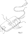
- Fig. 1 illustrates a general overview of the inventive concept with a valve actuator control device 1 (hereinafter referred to as control device 1) connected to a valve actuator 2 with a signal transmitting wire 3.
- the valve actuator may be provided with the appropriate socket/port 8 that matches at least one end 14 of the signal transmitting wire 3.
- the signal transmitting wire 3 may for example be a USB cable; hence the port 8 on the valve actuator may be a USB port.
- the valve actuator 2 is preferably arranged at a valve neck (not shown) which in turn is connected to a valve body of a control valve (not shown).
- the valve actuator 2 is generally utilized to control the flow rate of a fluid through the control valve as discussed in the background section.
- the signal transmitting wire 3 can be fixed to the control device 1 so that they form a single unit, or the signal transmitting wire 3 may be detachable both from the control device 1 and the valve actuator 2.
- the control device 1 is provided with a set of buttons 4, 5.
- the buttons 4, 5 serve merely to illustrate the functional concept and should not be considered as limiting to the scope of the invention, the buttons may instead be touch-sensitive areas or levers/joysticks, or any other equivalent solution providing a user-interface where physical stimuli is translated to electrical signals.
- the control device 1 has a set of control buttons 4, which may be used to adjust the stroke of the valve actuator 2, i.e. one button increases the variable opening in the control valve while the other one decreases the variable opening.
- the control buttons 4 may be seen as "manual mode" buttons, i.e. when pushed the valve actuator 2 is manually controlled to some extent.
- control device 1 may be provided with a set of configuration buttons 5.
- Pushing a configuration button may for example be that a set of predefined operating parameters, which are stored within the control device 1, are pushed on (uploaded to) the valve actuator 2 or a control unit within the valve actuator 2.
- a configuration button 5 may also be a reset button, i.e. when pushed a "reset" of the valve actuator 2 is performed, e.g. a factory reset or it may be a "connect button” in order to connect the device wirelessly to an external handheld device.
- a configuration button 5 may also be an automatic button, i.e. when pushed the valve actuator 2 goes in a fully automatic mode and operates according to the internally stored operating parameters.
- There may also be a set of programmable buttons in order to be able to store a set of predefined stroke positions, e.g. position 1, position 2 and position 3 which may be used to quickly set the stroke of a valve actuator at a certain position.
- a system according to the inventive concept allows for many more parameters to be configured than what is possible with conventional systems where the valve actuators are generally equipped with 10 - 12 jumpers or dipswitches.
- the control device 1 can for example be used to configure an input signal of the valve actuator as variants within a voltage range of 0 - 10 VDC or a current range within 0-20 mA.
- the input signal may accordingly be configured to be a split-range input signal e.g. 0-5/5-10 VDC, 0 - 4,5/5,5 - 10 VDC, 2-6/6-10 VDC, 0-10/10-20 mA, etc. depending on the desired application and hardware specifications (type of signal transmitting wire 3, actuator 2 hardware and/or control device 1 hardware).
- Many of the currently available actuators can take only one split-range at most.
- Other parameters that can easily be configured by utilizing the control device 1 are for example choice of characteristics, choice of output signal, choice of speed, stroke limitation, etc.
- the control device 1 may further comprise indicator lights 11, 12, 13, 15 for various functions, e.g. an "energy storage light” 11 which indicates if there is enough energy left in the energy storage unit (not shown) for successful operation and/or a “power light” light 15 for showing that the control device is currently on and operable.
- There may also be a "wireless light” 12 indicating if there is a handheld device connected to the control device 1.
- indicator lights 13 provided in association with every button 4, 5 on the control device 1 in order to notify the user if for example a certain button is not operable at a certain time (e.g. by changing colour of the indicator light).
- control device 1 may comprise a port 7 enabling charging of the energy storage unit (not shown), in particular if it is an internal energy storage unit.
- the port 7 can for example be a mini USB or micro USB port which enables charging of the energy storage unit via a USB cable that is connected to an energy source in a similar fashion as in today's smart phones or tablets.
- the charging port 7 may also be used to provide a wired connection to some external handheld device as well, e.g. to a computer, smart phone, PDA, tablet, etc.
- Fig. 3a-b illustrate the back-side 9 of a control device 1
- the back-side 9 is to be interpreted as the opposite side of the side having the primary user interface in the form of a set of buttons 4, 5 and indicator lights 11, 12, 13, 15.
- both sides may comprise buttons or indicator lights without going beyond the scope of the inventive concept.
- the back-side 9 may be removable from the main body of the control device 1 or have a lid 17 in order to allow for replacement or maintenance of internal parts, such as e.g. an (internal) energy storage unit 19.
- internal parts such as e.g. an (internal) energy storage unit 19.
- the backside 9 may also be provided with a recess 18b capable of receiving an (external) energy storage unit, here in the form of a battery 18a, which is placed within the recess 18b and locked in place with an appropriate locking mechanism 18c, e.g. rails, push-click elements, etc.
- a battery 18a which is placed within the recess 18b and locked in place with an appropriate locking mechanism 18c, e.g. rails, push-click elements, etc.
- an appropriate locking mechanism 18c e.g. rails, push-click elements, etc.
- Utilizing external batteries 18a is beneficial for situations where the control device 1 is intensely used and requires a quick battery change, so that you do not have to plug in the control device 1 and wait for the battery to be recharged. Instead one can quickly remove the battery 18a (and e.g. put it in a charging station) and attach a fully charged second external battery, thereby allowing for very time efficient operation.
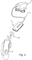
- Fig. 4 illustrates a handheld device 20 being wirelessly connected 22 to a control device 1 which in turn is connected to a valve actuator 2 via a signal transmitting wire 3.
- the wireless connection 22 can either be initiated and setup by the handheld device 20, through e.g. a Bluetooth connection or similar connection, or it may require an approval by the control device as well through e.g. pressing a button on the control device 1.
- a connection 22 has been established between the handheld device 20 and the control device 1
- the handheld device 20 may also be used to configure the control device 1 once a connection 22 has been established.
- the established connection may be indicated by an indicator light, e.g.
- the handheld device 20 could be provided with appropriate software and/or hardware in order to directly control and/or communicate with the valve actuator 2 via a signal transmitting wire 3.
- the handheld device 20 could then effectively be used as a valve actuator control device 1, e.g. to directly configure the valve actuator 2 or extract data-logs from the valve actuator 2 directly.
- Fig. 5 illustrates a flow chart representing a method for controlling a valve actuator when it is disconnected from a grid.
- a valve actuator control device is provided 501, which is connected 502 to a valve actuator with a signal transmitting wire.
- Operating power is then supplied 503 from an energy storage unit of the control device to the valve actuator, this is in order to enable operation of the valve actuator and consequently of the associated control valve since the actuator is disconnected from the grid.
- This feature is useful in situations where a new valve actuator is to be installed at larger sites and needs to be tested before it is connected to the general grid of valve actuators.
- control device may be used to transmit 504 control signals to the valve actuator, where the control signals may either be intended for configuration 504a, direct control 504b, automation 504c or any of the previously mentioned functions.
- Direct control can e.g. be to adjust the variable opening of the control valve based on direct input (e.g. push of a button) on the control device, while automation may be to set the valve actuator to run in an automatic mode according to a set of internal operating parameters of the valve actuator.
- the control device may also be used to receive 505 data or information about the internal parameters of the control device or to extract operating data logs/error logs.
- the received 505 data may in turn be forwarded 506 to a handheld device (e.g. smart phone or tablet) which is wirelessly connected to the control device.
- the handheld device may then process the received data in order to perform diagnostics or upload it to a remote server 510 for e.g. statistical purposes.
- the handheld device can also be used to control the valve actuator via control signals 504a-c forwarded
Landscapes
- Engineering & Computer Science (AREA)
- General Engineering & Computer Science (AREA)
- Mechanical Engineering (AREA)
- Physics & Mathematics (AREA)
- General Physics & Mathematics (AREA)
- Automation & Control Theory (AREA)
- Indication Of The Valve Opening Or Closing Status (AREA)
Claims (12)
- Procédé pour la commande d'un actionneur de soupape (2) lorsque celui-ci est déconnecté d'une grille, ledit procédé comprenant les étapes suivantes :mise à disposition (501) d'un dispositif de commande d'actionneur de soupape (1) portatif et apte à être relié à l'actionneur de soupape à l'aide d'un câble de transmission de signal (3) ;raccordement (502) du dispositif de commande d'actionneur de soupape à l'actionneur de soupape à l'aide du câble de transmission de signal ;apport (503) d'une puissance de fonctionnement à l'actionneur de soupape à partir d'une unité de stockage d'énergie reliée au dispositif de commande d'actionneur de soupape ;transmission (504) de signaux de commande depuis le dispositif de commande d'actionneur de soupape à l'actionneur de soupape par le biais dudit câble de transmission de signal pour commander l'actionneur de soupape ;caractérisé en ce que ledit procédé comprend en outre :la réception (505) de signaux d'information envoyés de l'actionneur de soupape au dispositif de commande d'actionneur de soupape par le biais dudit câble de transmission de signal pour extraire un ensemble de paramètres internes de l'actionneur de soupape ; etla détection d'un type de modèle dudit actionneur de soupape à partir des signaux d'information reçus en provenance de l'actionneur de soupape.
- Procédé selon l'une quelconque des revendications précédentes, dans lequel ledit câble de transmission de signal (3) est un câble USB (Bus série universel).
- Procédé selon l'une quelconque des revendications précédentes, comprenant en outre l'étape suivante :établissement d'une connexion entre un dispositif à main portatif (20) et le dispositif de commande d'actionneur de soupape (1).
- Procédé selon l'une quelconque des revendications précédentes, comprenant en outre l'étape suivante :configuration (504a) de l'actionneur de soupape en fonction d'un ensemble de paramètres prédéfinis stockés dans une unité de stockage à mémoire dans le dispositif de commande d'actionneur de soupape (1), par :le téléchargement dudit ensemble de paramètres prédéfinis à partir dudit dispositif de commande d'actionneur de soupape vers une unité de commande dans l'actionneur de soupape (2).
- Dispositif de commande d'actionneur de soupape (1) destiné à commander un actionneur de soupape (2), ledit dispositif de commande d'actionneur de soupape étant un dispositif portatif externe et apte à être relié à l'actionneur de soupape par le biais d'un câble de transmission de signal (3), ledit dispositif de commande d'actionneur de soupape comprenant :une unité de stockage d'énergie (18a, 19) destinée à fournir de l'énergie au dispositif de commande d'actionneur de soupape (1) ;une unité de transmission destinée à transmettre des signaux de commande à l'actionneur de soupape (2) par le biais dudit câble de transmission de signal afin de commander l'actionneur de soupape ;caractérisé en ce que ledit dispositif de commande d'actionneur de soupape comprend en outre :une unité de réception destinée à recevoir des signaux d'information envoyés par l'actionneur de soupape par le biais dudit câble de transmission de signal (3) afin d'extraire un ensemble de paramètres internes de l'actionneur de soupape, et en ce que ledit dispositif de commande d'actionneur de soupape est configuré pour déterminer un type de modèle dudit actionneur de soupape sur la base des informations reçues.
- Dispositif de commande d'actionneur de soupape (1) selon la revendication 5, comprenant en outre la mise à disposition de circuits destinés à fournir une puissance de fonctionnement à l'actionneur de soupape à l'aide de ladite unité de stockage d'énergie.
- Dispositif de commande d'actionneur de soupape (1) selon la revendication 6, dans lequel ladite puissance de fonctionnement est fournie par le biais dudit câble de transmission de signal.
- Dispositif de commande d'actionneur de soupape (1) selon l'une quelconque des revendications 5 à 7, comprenant en outre une unité de communication configurée pour établir une connexion avec un dispositif à main portatif.
- Dispositif de commande d'actionneur de soupape (1) selon l'une quelconque des revendications 5 à 8, comprenant en outre au moins un bouton (4, 5) envoyant un signal de commande à l'actionneur de soupape (2) par le biais dudit câble de transmission de signal (3) lorsqu'il est pressé.
- Dispositif de commande d'actionneur de soupape (1) selon la revendication 9, comprenant en outre une unité de mémoire, dans lequel ledit signal de commande est un ensemble de paramètres de fonctionnement prédéfinis de l'actionneur de soupape (2), lesdits paramètres de fonctionnement étant extraits à partir de ladite unité de mémoire.
- Ensemble d'actionneur de soupape pour un système de distribution de fluide, ledit ensemble comprenant :une soupape comprenant :un corps de soupape ;une chambre disposée à l'intérieur dudit corps de soupape ;une entrée de fluide et une sortie de fluide ;un ensemble de fermeture de soupape destiné à réguler l'écoulement de fluide de ladite entrée de fluide vers ladite sortie de fluide par le biais de ladite chambre ;ledit ensemble de fermeture présentant une position fermée, dans laquelle aucun fluide ne peut s'écouler à travers la chambre, et une position entièrement ouverte, dans laquelle un fluide peut s'écouler à travers ladite chambre, ledit ensemble comprenant en outre :un actionneur de soupape (2) destiné à actionner ledit ensemble de fermeture de soupape,un dispositif de commande d'actionneur de soupape (1) selon l'une quelconque des revendications 5 à 10 ;dans lequel ledit actionneur de soupape comprend des moyens pour établir une connexion avec ledit dispositif de commande d'actionneur de soupape par le biais d'un câble de transmission de signal (3).
- Ensemble d'actionneur de soupape selon la revendication 11, dans lequel ledit actionneur de soupape (2) comporte une unité de commande comprenant une unité de mémoire configurée pour recevoir et stocker une valeur de limitation d'ouverture, ladite valeur de limitation d'ouverture étant représentative d'une position intermédiaire sélectionnée entre ladite position fermée et ladite position entièrement ouverte,
dans lequel l'unité de commande permet de commander l'actionneur afin de limiter le déplacement de l'ensemble de fermeture vers des positions de ladite position fermée vers ladite position intermédiaire sélectionnée, et dans lequel ledit dispositif de commande d'actionneur de soupape (1) comprend des moyens pour remplacer la valeur de limitation d'ouverture dans ladite unité de mémoire, par une nouvelle valeur de limitation d'ouverture.
Priority Applications (2)
| Application Number | Priority Date | Filing Date | Title |
|---|---|---|---|
| EP15191197.1A EP3159588B1 (fr) | 2015-10-23 | 2015-10-23 | Procédé de commande d'un actionneur de soupape et dispositif de commande d'un actionneur de soupape |
| US15/299,971 US10268211B2 (en) | 2015-10-23 | 2016-10-21 | Method for controlling a valve actuator and a valve actuator control device |
Applications Claiming Priority (1)
| Application Number | Priority Date | Filing Date | Title |
|---|---|---|---|
| EP15191197.1A EP3159588B1 (fr) | 2015-10-23 | 2015-10-23 | Procédé de commande d'un actionneur de soupape et dispositif de commande d'un actionneur de soupape |
Publications (2)
| Publication Number | Publication Date |
|---|---|
| EP3159588A1 EP3159588A1 (fr) | 2017-04-26 |
| EP3159588B1 true EP3159588B1 (fr) | 2018-04-25 |
Family
ID=54476686
Family Applications (1)
| Application Number | Title | Priority Date | Filing Date |
|---|---|---|---|
| EP15191197.1A Active EP3159588B1 (fr) | 2015-10-23 | 2015-10-23 | Procédé de commande d'un actionneur de soupape et dispositif de commande d'un actionneur de soupape |
Country Status (2)
| Country | Link |
|---|---|
| US (1) | US10268211B2 (fr) |
| EP (1) | EP3159588B1 (fr) |
Families Citing this family (2)
| Publication number | Priority date | Publication date | Assignee | Title |
|---|---|---|---|---|
| JP2019210988A (ja) * | 2018-06-04 | 2019-12-12 | 日本ギア工業株式会社 | 電動バルブアクチュエータ |
| WO2022083933A1 (fr) * | 2020-10-22 | 2022-04-28 | Belimo Holding Ag | Actionneur de chauffage, de ventilation et de climatisation |
Family Cites Families (9)
| Publication number | Priority date | Publication date | Assignee | Title |
|---|---|---|---|---|
| US4760547A (en) * | 1985-09-24 | 1988-07-26 | Duxbury Jonathan W | Remote controlled multi-station irrigation system with DTMF transmitter |
| DE68920427T2 (de) * | 1988-10-04 | 1995-05-11 | Solatrol Inc | Zentralverwaltungssystem der bewässerungseinheiten. |
| US20040004200A1 (en) * | 2002-07-08 | 2004-01-08 | Pescatore Ronald C. | Method and apparatus for flow control in independent units |
| US7844367B2 (en) * | 2003-12-23 | 2010-11-30 | Rain Bird Corporation | Code replacement for irrigation controllers |
| US7066192B1 (en) * | 2004-08-04 | 2006-06-27 | Brian Delaney | Valve shut off device |
| US20100000612A1 (en) * | 2007-12-07 | 2010-01-07 | Innovative Technology Concepts, Inc. | Remotely activated manifold shut-off and method of using the same |
| GB2461521B (en) * | 2008-07-01 | 2012-11-07 | Amsafe Bridport Ltd | A buckle |
| US8606373B2 (en) * | 2009-04-22 | 2013-12-10 | Elkhart Brass Manufacturing Company, Inc. | Firefighting monitor and control system therefor |
| EP3489557B1 (fr) | 2013-12-20 | 2020-04-22 | IMI Hydronic Engineering International SA | Soupape et procédé de fonctionnement d'une soupape |
-
2015
- 2015-10-23 EP EP15191197.1A patent/EP3159588B1/fr active Active
-
2016
- 2016-10-21 US US15/299,971 patent/US10268211B2/en active Active
Non-Patent Citations (1)
| Title |
|---|
| None * |
Also Published As
| Publication number | Publication date |
|---|---|
| US20170115669A1 (en) | 2017-04-27 |
| US10268211B2 (en) | 2019-04-23 |
| EP3159588A1 (fr) | 2017-04-26 |
Similar Documents
| Publication | Publication Date | Title |
|---|---|---|
| US10261530B2 (en) | Control device, components, and mobile service device for an HVAC system | |
| EP3060814B1 (fr) | Systeme et procede de commande à distance d'une valve | |
| EP3005247B1 (fr) | Système rfid à longue portée dans un système de contrôle de processus | |
| CN102230658B (zh) | 一种空调风机电机控制器及其控制方法 | |
| CN118140467B (zh) | 分布式通信与控制系统,通信集线器和用于配置可重新配置连接端口的方法 | |
| EP3159588B1 (fr) | Procédé de commande d'un actionneur de soupape et dispositif de commande d'un actionneur de soupape | |
| JP4906914B2 (ja) | 電力伝送フィールド装置 | |
| CN104076788B (zh) | 基于传感器的智能继电器的控制方法及网络 | |
| CN105892419B (zh) | 用于自动化技术中的系统 | |
| CN103180795A (zh) | 阀系统 | |
| US11320163B2 (en) | Actuator with a USB interface | |
| WO2020229264A1 (fr) | Actionneurs intermittents alimentés par connexion à fil torsadé | |
| US10859285B2 (en) | Control adapter for fastening on a device of an HVAC system | |
| US9948757B2 (en) | Field device | |
| CN105091216A (zh) | 空调机组控制系统 | |
| EP3719366B1 (fr) | Organe de commande d'actionneur | |
| CN220818025U (zh) | 用于中央空调的控制装置和中央空调 | |
| CN204389676U (zh) | 遥控雷达系统 | |
| US20240167715A1 (en) | System and method for scheduling a variable refrigerant flow (vrf) system in accordance with a programmable schedule | |
| CN202150108U (zh) | 实现数据传输的模式转换装置 | |
| HK1227191A1 (en) | Field device |
Legal Events
| Date | Code | Title | Description |
|---|---|---|---|
| PUAI | Public reference made under article 153(3) epc to a published international application that has entered the european phase |
Free format text: ORIGINAL CODE: 0009012 |
|
| AK | Designated contracting states |
Kind code of ref document: A1 Designated state(s): AL AT BE BG CH CY CZ DE DK EE ES FI FR GB GR HR HU IE IS IT LI LT LU LV MC MK MT NL NO PL PT RO RS SE SI SK SM TR |
|
| AX | Request for extension of the european patent |
Extension state: BA ME |
|
| 17P | Request for examination filed |
Effective date: 20171017 |
|
| RBV | Designated contracting states (corrected) |
Designated state(s): AL AT BE BG CH CY CZ DE DK EE ES FI FR GB GR HR HU IE IS IT LI LT LU LV MC MK MT NL NO PL PT RO RS SE SI SK SM TR |
|
| GRAP | Despatch of communication of intention to grant a patent |
Free format text: ORIGINAL CODE: EPIDOSNIGR1 |
|
| INTG | Intention to grant announced |
Effective date: 20180103 |
|
| GRAA | (expected) grant |
Free format text: ORIGINAL CODE: 0009210 |
|
| GRAS | Grant fee paid |
Free format text: ORIGINAL CODE: EPIDOSNIGR3 |
|
| AK | Designated contracting states |
Kind code of ref document: B1 Designated state(s): AL AT BE BG CH CY CZ DE DK EE ES FI FR GB GR HR HU IE IS IT LI LT LU LV MC MK MT NL NO PL PT RO RS SE SI SK SM TR |
|
| REG | Reference to a national code |
Ref country code: GB Ref legal event code: FG4D |
|
| REG | Reference to a national code |
Ref country code: CH Ref legal event code: EP |
|
| REG | Reference to a national code |
Ref country code: AT Ref legal event code: REF Ref document number: 993287 Country of ref document: AT Kind code of ref document: T Effective date: 20180515 |
|
| REG | Reference to a national code |
Ref country code: IE Ref legal event code: FG4D |
|
| REG | Reference to a national code |
Ref country code: DE Ref legal event code: R096 Ref document number: 602015010351 Country of ref document: DE |
|
| REG | Reference to a national code |
Ref country code: SE Ref legal event code: TRGR |
|
| REG | Reference to a national code |
Ref country code: NL Ref legal event code: MP Effective date: 20180425 |
|
| REG | Reference to a national code |
Ref country code: LT Ref legal event code: MG4D |
|
| REG | Reference to a national code |
Ref country code: FR Ref legal event code: PLFP Year of fee payment: 4 |
|
| PG25 | Lapsed in a contracting state [announced via postgrant information from national office to epo] |
Ref country code: NL Free format text: LAPSE BECAUSE OF FAILURE TO SUBMIT A TRANSLATION OF THE DESCRIPTION OR TO PAY THE FEE WITHIN THE PRESCRIBED TIME-LIMIT Effective date: 20180425 |
|
| PG25 | Lapsed in a contracting state [announced via postgrant information from national office to epo] |
Ref country code: ES Free format text: LAPSE BECAUSE OF FAILURE TO SUBMIT A TRANSLATION OF THE DESCRIPTION OR TO PAY THE FEE WITHIN THE PRESCRIBED TIME-LIMIT Effective date: 20180425 Ref country code: LT Free format text: LAPSE BECAUSE OF FAILURE TO SUBMIT A TRANSLATION OF THE DESCRIPTION OR TO PAY THE FEE WITHIN THE PRESCRIBED TIME-LIMIT Effective date: 20180425 Ref country code: PL Free format text: LAPSE BECAUSE OF FAILURE TO SUBMIT A TRANSLATION OF THE DESCRIPTION OR TO PAY THE FEE WITHIN THE PRESCRIBED TIME-LIMIT Effective date: 20180425 Ref country code: FI Free format text: LAPSE BECAUSE OF FAILURE TO SUBMIT A TRANSLATION OF THE DESCRIPTION OR TO PAY THE FEE WITHIN THE PRESCRIBED TIME-LIMIT Effective date: 20180425 Ref country code: BG Free format text: LAPSE BECAUSE OF FAILURE TO SUBMIT A TRANSLATION OF THE DESCRIPTION OR TO PAY THE FEE WITHIN THE PRESCRIBED TIME-LIMIT Effective date: 20180725 Ref country code: NO Free format text: LAPSE BECAUSE OF FAILURE TO SUBMIT A TRANSLATION OF THE DESCRIPTION OR TO PAY THE FEE WITHIN THE PRESCRIBED TIME-LIMIT Effective date: 20180725 |
|
| PG25 | Lapsed in a contracting state [announced via postgrant information from national office to epo] |
Ref country code: RS Free format text: LAPSE BECAUSE OF FAILURE TO SUBMIT A TRANSLATION OF THE DESCRIPTION OR TO PAY THE FEE WITHIN THE PRESCRIBED TIME-LIMIT Effective date: 20180425 Ref country code: HR Free format text: LAPSE BECAUSE OF FAILURE TO SUBMIT A TRANSLATION OF THE DESCRIPTION OR TO PAY THE FEE WITHIN THE PRESCRIBED TIME-LIMIT Effective date: 20180425 Ref country code: GR Free format text: LAPSE BECAUSE OF FAILURE TO SUBMIT A TRANSLATION OF THE DESCRIPTION OR TO PAY THE FEE WITHIN THE PRESCRIBED TIME-LIMIT Effective date: 20180726 Ref country code: LV Free format text: LAPSE BECAUSE OF FAILURE TO SUBMIT A TRANSLATION OF THE DESCRIPTION OR TO PAY THE FEE WITHIN THE PRESCRIBED TIME-LIMIT Effective date: 20180425 |
|
| REG | Reference to a national code |
Ref country code: AT Ref legal event code: MK05 Ref document number: 993287 Country of ref document: AT Kind code of ref document: T Effective date: 20180425 |
|
| PG25 | Lapsed in a contracting state [announced via postgrant information from national office to epo] |
Ref country code: PT Free format text: LAPSE BECAUSE OF FAILURE TO SUBMIT A TRANSLATION OF THE DESCRIPTION OR TO PAY THE FEE WITHIN THE PRESCRIBED TIME-LIMIT Effective date: 20180827 |
|
| REG | Reference to a national code |
Ref country code: DE Ref legal event code: R097 Ref document number: 602015010351 Country of ref document: DE |
|
| PG25 | Lapsed in a contracting state [announced via postgrant information from national office to epo] |
Ref country code: SK Free format text: LAPSE BECAUSE OF FAILURE TO SUBMIT A TRANSLATION OF THE DESCRIPTION OR TO PAY THE FEE WITHIN THE PRESCRIBED TIME-LIMIT Effective date: 20180425 Ref country code: DK Free format text: LAPSE BECAUSE OF FAILURE TO SUBMIT A TRANSLATION OF THE DESCRIPTION OR TO PAY THE FEE WITHIN THE PRESCRIBED TIME-LIMIT Effective date: 20180425 Ref country code: CZ Free format text: LAPSE BECAUSE OF FAILURE TO SUBMIT A TRANSLATION OF THE DESCRIPTION OR TO PAY THE FEE WITHIN THE PRESCRIBED TIME-LIMIT Effective date: 20180425 Ref country code: RO Free format text: LAPSE BECAUSE OF FAILURE TO SUBMIT A TRANSLATION OF THE DESCRIPTION OR TO PAY THE FEE WITHIN THE PRESCRIBED TIME-LIMIT Effective date: 20180425 Ref country code: AT Free format text: LAPSE BECAUSE OF FAILURE TO SUBMIT A TRANSLATION OF THE DESCRIPTION OR TO PAY THE FEE WITHIN THE PRESCRIBED TIME-LIMIT Effective date: 20180425 Ref country code: EE Free format text: LAPSE BECAUSE OF FAILURE TO SUBMIT A TRANSLATION OF THE DESCRIPTION OR TO PAY THE FEE WITHIN THE PRESCRIBED TIME-LIMIT Effective date: 20180425 |
|
| PG25 | Lapsed in a contracting state [announced via postgrant information from national office to epo] |
Ref country code: SM Free format text: LAPSE BECAUSE OF FAILURE TO SUBMIT A TRANSLATION OF THE DESCRIPTION OR TO PAY THE FEE WITHIN THE PRESCRIBED TIME-LIMIT Effective date: 20180425 Ref country code: IT Free format text: LAPSE BECAUSE OF FAILURE TO SUBMIT A TRANSLATION OF THE DESCRIPTION OR TO PAY THE FEE WITHIN THE PRESCRIBED TIME-LIMIT Effective date: 20180425 |
|
| PLBE | No opposition filed within time limit |
Free format text: ORIGINAL CODE: 0009261 |
|
| STAA | Information on the status of an ep patent application or granted ep patent |
Free format text: STATUS: NO OPPOSITION FILED WITHIN TIME LIMIT |
|
| 26N | No opposition filed |
Effective date: 20190128 |
|
| PG25 | Lapsed in a contracting state [announced via postgrant information from national office to epo] |
Ref country code: SI Free format text: LAPSE BECAUSE OF FAILURE TO SUBMIT A TRANSLATION OF THE DESCRIPTION OR TO PAY THE FEE WITHIN THE PRESCRIBED TIME-LIMIT Effective date: 20180425 |
|
| REG | Reference to a national code |
Ref country code: CH Ref legal event code: PL |
|
| REG | Reference to a national code |
Ref country code: BE Ref legal event code: MM Effective date: 20181031 |
|
| PG25 | Lapsed in a contracting state [announced via postgrant information from national office to epo] |
Ref country code: MC Free format text: LAPSE BECAUSE OF FAILURE TO SUBMIT A TRANSLATION OF THE DESCRIPTION OR TO PAY THE FEE WITHIN THE PRESCRIBED TIME-LIMIT Effective date: 20180425 Ref country code: LU Free format text: LAPSE BECAUSE OF NON-PAYMENT OF DUE FEES Effective date: 20181023 |
|
| REG | Reference to a national code |
Ref country code: IE Ref legal event code: MM4A |
|
| PG25 | Lapsed in a contracting state [announced via postgrant information from national office to epo] |
Ref country code: BE Free format text: LAPSE BECAUSE OF NON-PAYMENT OF DUE FEES Effective date: 20181031 Ref country code: CH Free format text: LAPSE BECAUSE OF NON-PAYMENT OF DUE FEES Effective date: 20181031 Ref country code: LI Free format text: LAPSE BECAUSE OF NON-PAYMENT OF DUE FEES Effective date: 20181031 |
|
| PG25 | Lapsed in a contracting state [announced via postgrant information from national office to epo] |
Ref country code: IE Free format text: LAPSE BECAUSE OF NON-PAYMENT OF DUE FEES Effective date: 20181023 |
|
| PG25 | Lapsed in a contracting state [announced via postgrant information from national office to epo] |
Ref country code: AL Free format text: LAPSE BECAUSE OF FAILURE TO SUBMIT A TRANSLATION OF THE DESCRIPTION OR TO PAY THE FEE WITHIN THE PRESCRIBED TIME-LIMIT Effective date: 20180425 |
|
| PG25 | Lapsed in a contracting state [announced via postgrant information from national office to epo] |
Ref country code: MT Free format text: LAPSE BECAUSE OF NON-PAYMENT OF DUE FEES Effective date: 20181023 |
|
| PG25 | Lapsed in a contracting state [announced via postgrant information from national office to epo] |
Ref country code: TR Free format text: LAPSE BECAUSE OF FAILURE TO SUBMIT A TRANSLATION OF THE DESCRIPTION OR TO PAY THE FEE WITHIN THE PRESCRIBED TIME-LIMIT Effective date: 20180425 |
|
| PG25 | Lapsed in a contracting state [announced via postgrant information from national office to epo] |
Ref country code: CY Free format text: LAPSE BECAUSE OF FAILURE TO SUBMIT A TRANSLATION OF THE DESCRIPTION OR TO PAY THE FEE WITHIN THE PRESCRIBED TIME-LIMIT Effective date: 20180425 Ref country code: MK Free format text: LAPSE BECAUSE OF NON-PAYMENT OF DUE FEES Effective date: 20180425 Ref country code: HU Free format text: LAPSE BECAUSE OF FAILURE TO SUBMIT A TRANSLATION OF THE DESCRIPTION OR TO PAY THE FEE WITHIN THE PRESCRIBED TIME-LIMIT; INVALID AB INITIO Effective date: 20151023 |
|
| PG25 | Lapsed in a contracting state [announced via postgrant information from national office to epo] |
Ref country code: IS Free format text: LAPSE BECAUSE OF FAILURE TO SUBMIT A TRANSLATION OF THE DESCRIPTION OR TO PAY THE FEE WITHIN THE PRESCRIBED TIME-LIMIT Effective date: 20180825 |
|
| P01 | Opt-out of the competence of the unified patent court (upc) registered |
Effective date: 20230530 |
|
| REG | Reference to a national code |
Ref country code: DE Ref legal event code: R082 Ref document number: 602015010351 Country of ref document: DE |
|
| PGFP | Annual fee paid to national office [announced via postgrant information from national office to epo] |
Ref country code: GB Payment date: 20250822 Year of fee payment: 11 |
|
| PGFP | Annual fee paid to national office [announced via postgrant information from national office to epo] |
Ref country code: FR Payment date: 20250820 Year of fee payment: 11 |
|
| PGFP | Annual fee paid to national office [announced via postgrant information from national office to epo] |
Ref country code: SE Payment date: 20250820 Year of fee payment: 11 |
|
| PGFP | Annual fee paid to national office [announced via postgrant information from national office to epo] |
Ref country code: DE Payment date: 20250917 Year of fee payment: 11 |