EP3165762A1 - Wind turbine blade - Google Patents
Wind turbine blade Download PDFInfo
- Publication number
- EP3165762A1 EP3165762A1 EP15382547.6A EP15382547A EP3165762A1 EP 3165762 A1 EP3165762 A1 EP 3165762A1 EP 15382547 A EP15382547 A EP 15382547A EP 3165762 A1 EP3165762 A1 EP 3165762A1
- Authority
- EP
- European Patent Office
- Prior art keywords
- lateral
- spar
- wind turbine
- turbine blade
- bonding
- Prior art date
- Legal status (The legal status is an assumption and is not a legal conclusion. Google has not performed a legal analysis and makes no representation as to the accuracy of the status listed.)
- Granted
Links
Images



Classifications
-
- F—MECHANICAL ENGINEERING; LIGHTING; HEATING; WEAPONS; BLASTING
- F03—MACHINES OR ENGINES FOR LIQUIDS; WIND, SPRING, OR WEIGHT MOTORS; PRODUCING MECHANICAL POWER OR A REACTIVE PROPULSIVE THRUST, NOT OTHERWISE PROVIDED FOR
- F03D—WIND MOTORS
- F03D1/00—Wind motors with rotation axis substantially parallel to the air flow entering the rotor
- F03D1/06—Rotors
- F03D1/065—Rotors characterised by their construction elements
- F03D1/0675—Rotors characterised by their construction elements of the blades
-
- F—MECHANICAL ENGINEERING; LIGHTING; HEATING; WEAPONS; BLASTING
- F05—INDEXING SCHEMES RELATING TO ENGINES OR PUMPS IN VARIOUS SUBCLASSES OF CLASSES F01-F04
- F05B—INDEXING SCHEME RELATING TO WIND, SPRING, WEIGHT, INERTIA OR LIKE MOTORS, TO MACHINES OR ENGINES FOR LIQUIDS COVERED BY SUBCLASSES F03B, F03D AND F03G
- F05B2230/00—Manufacture
- F05B2230/30—Manufacture with deposition of material
- F05B2230/31—Layer deposition
- F05B2230/311—Layer deposition by torch or flame spray
-
- F—MECHANICAL ENGINEERING; LIGHTING; HEATING; WEAPONS; BLASTING
- F05—INDEXING SCHEMES RELATING TO ENGINES OR PUMPS IN VARIOUS SUBCLASSES OF CLASSES F01-F04
- F05B—INDEXING SCHEME RELATING TO WIND, SPRING, WEIGHT, INERTIA OR LIKE MOTORS, TO MACHINES OR ENGINES FOR LIQUIDS COVERED BY SUBCLASSES F03B, F03D AND F03G
- F05B2240/00—Components
- F05B2240/20—Rotors
- F05B2240/21—Rotors for wind turbines
- F05B2240/221—Rotors for wind turbines with horizontal axis
- F05B2240/2211—Rotors for wind turbines with horizontal axis of the multibladed, low speed, e.g. "American farm" type
-
- F—MECHANICAL ENGINEERING; LIGHTING; HEATING; WEAPONS; BLASTING
- F05—INDEXING SCHEMES RELATING TO ENGINES OR PUMPS IN VARIOUS SUBCLASSES OF CLASSES F01-F04
- F05B—INDEXING SCHEME RELATING TO WIND, SPRING, WEIGHT, INERTIA OR LIKE MOTORS, TO MACHINES OR ENGINES FOR LIQUIDS COVERED BY SUBCLASSES F03B, F03D AND F03G
- F05B2240/00—Components
- F05B2240/20—Rotors
- F05B2240/30—Characteristics of rotor blades, i.e. of any element transforming dynamic fluid energy to or from rotational energy and being attached to a rotor
- F05B2240/301—Cross-section characteristics
-
- F—MECHANICAL ENGINEERING; LIGHTING; HEATING; WEAPONS; BLASTING
- F05—INDEXING SCHEMES RELATING TO ENGINES OR PUMPS IN VARIOUS SUBCLASSES OF CLASSES F01-F04
- F05B—INDEXING SCHEME RELATING TO WIND, SPRING, WEIGHT, INERTIA OR LIKE MOTORS, TO MACHINES OR ENGINES FOR LIQUIDS COVERED BY SUBCLASSES F03B, F03D AND F03G
- F05B2280/00—Materials; Properties thereof
- F05B2280/60—Properties or characteristics given to material by treatment or manufacturing
- F05B2280/6003—Composites; e.g. fibre-reinforced
-
- Y—GENERAL TAGGING OF NEW TECHNOLOGICAL DEVELOPMENTS; GENERAL TAGGING OF CROSS-SECTIONAL TECHNOLOGIES SPANNING OVER SEVERAL SECTIONS OF THE IPC; TECHNICAL SUBJECTS COVERED BY FORMER USPC CROSS-REFERENCE ART COLLECTIONS [XRACs] AND DIGESTS
- Y02—TECHNOLOGIES OR APPLICATIONS FOR MITIGATION OR ADAPTATION AGAINST CLIMATE CHANGE
- Y02E—REDUCTION OF GREENHOUSE GAS [GHG] EMISSIONS, RELATED TO ENERGY GENERATION, TRANSMISSION OR DISTRIBUTION
- Y02E10/00—Energy generation through renewable energy sources
- Y02E10/70—Wind energy
- Y02E10/72—Wind turbines with rotation axis in wind direction
-
- Y—GENERAL TAGGING OF NEW TECHNOLOGICAL DEVELOPMENTS; GENERAL TAGGING OF CROSS-SECTIONAL TECHNOLOGIES SPANNING OVER SEVERAL SECTIONS OF THE IPC; TECHNICAL SUBJECTS COVERED BY FORMER USPC CROSS-REFERENCE ART COLLECTIONS [XRACs] AND DIGESTS
- Y02—TECHNOLOGIES OR APPLICATIONS FOR MITIGATION OR ADAPTATION AGAINST CLIMATE CHANGE
- Y02P—CLIMATE CHANGE MITIGATION TECHNOLOGIES IN THE PRODUCTION OR PROCESSING OF GOODS
- Y02P70/00—Climate change mitigation technologies in the production process for final industrial or consumer products
- Y02P70/50—Manufacturing or production processes characterised by the final manufactured product
Definitions
- the present invention falls within the technical field of wind turbines. More specifically, it disclosed a wind turbine blade having an enhanced bond between the spar and inner surface of the blade.
- wind turbine blades have a pressure surface and a suction surface consisting of laminated composite material joined therebetween and which confer the aerodynamic geometry to the blade.
- the connection of the pressure and suction surfaces is performed joining their ends and by means of spars disposed in the cavity formed by said pressure and suction surfaces.
- the spars stiffen the pressure and suction surfaces to avoid bending of the laminates that form them.
- the connection between the spars and pressure and suction surfaces can be executed in various manners, but the most common is bonding by means of adhesive.
- the blades are formed by a continuous surface, there not existing a bond defined between the pressure and suction surfaces. Also in these cases, the spars stiffen said pressure and suction surfaces and the bond between those and these is usually executed by means of adhesive.
- the conventional geometry of the spars is I- or C-shaped, although spars having L- or T-shaped and even X- or K-shaped geometries are also known.
- the selection of one type of geometry or another depends on the structural requirements in terms of capacity to transmit the shear stress experienced by the blade due to aerodynamic loads and other solicitations arising during wind turbine operation. This shear stress is transmitted from the spars to the pressure and suction surfaces through the bond thereof which, as described previously, is usually an adhesive bond.
- the spars comprise:
- the central zone of the spar is disposed substantially transversely or obliquely to the blade pressure and suction surfaces.
- the spar bonding zones allow adhesive bonding to the blade pressure and suction surfaces and comprise at least one bonding surface substantially parallel to said blade pressure and suction surfaces.
- each fibre fabric layer of the core forms a shear stress transmission layer such that the spar usually comprises two layers.
- the shear stress must be absorbed by the fibre fabric layers, the distribution of shear stress in the adhesive is not even, generating two shear stress tension peaks corresponding to each of the fibre fabric layers.
- the present invention describes a wind turbine blade having at least one spar configured to enhance the adhesive bonding thereof to the inner surface of the longitudinal hollow element of the blade.
- the spar makes it possible, due to a more homogeneous distribution of shear stress in said bond, to reduce the width of said adhesive bond and enhance the transfer of shear stress between the inner surface of the longitudinal hollow element and the spar itself. This in turn makes it possible to use less adhesive material.
- the blade of the present invention makes it possible to even out the distribution of shear stress in the adhesive bonding zone between the inner surface of the longitudinal hollow element and the spar, minimising in turn the peak values of said stress.
- the proposed blade comprises at least one longitudinal hollow element that defines an aerodynamic outer surface with a pressure zone and a suction zone, and an inner cavity having an inner surface which, in turn, has a zone corresponding to the pressure zone and a zone corresponding to the suction zone.
- the blade comprises at least one spar disposed in the inner cavity and joined to the inner surface by at least two bonding surfaces disposed in the spar bonding zones.
- the spar of the blade of the present invention comprises, in the spar bonding zones, which are preferably joined to the inner surface by means of an adhesive bond, a larger number of fibre fabric layers than the spars of the state of the art (it comprises at least three layers compared to two layers in the spars of the state of the art), separated therebetween by cores.
- the fibre fabric layers which form the spar stress transmission layers that transmit stress to the inner surface of the longitudinal hollow element are disposed parallel therebetween and transversely or obliquely with respect to the inner surfaces in the blade suction and pressure zones.
- the spar has, in the adhesive bonding zone, at least three fibre fabric layers and a group of cores having at least two cores.
- the layout of the fibre layers with respect to the cores may depend on the loads of the blade in accordance with the type of wind to be supported, where it is installed, etc. This spar configuration allows a more even distribution of the stress in the adhesive bond between the spar and the inner surface of the longitudinal hollow element of the blade.
- the at least one spar of the blade described comprises, in the adhesive bonding zone, a number of fibre fabric layers (i.e. shear stress transmission layers) equal to or greater than three. Said at least three layers are separated by at least two cores in the bonding zone of the spar to the blade pressure and suction surfaces.
- each of the cores of the present invention is disposed between at least two fibre fabric layers.
- this configuration makes it possible to reduce the maximum shear stress magnitude in the bond between the spars and the blade pressure and suction surfaces. This also results in a reduction in the width of the spar in the bonding zone (the bonding surface of the spar is reduced), making it possible to save a large amount of adhesive and avoid the use of additional bonding and reinforcement elements external to the spar itself.
- each spar comprises a central core and at least one lateral core.
- the geometry of the lateral cores is such that, in the bonding zone, all the fibre fabric layers (i.e. all the stress transmission layers) are substantially parallel.
- the at least one lateral core comprises an adjacent side, at least one side divergent with respect to, at least, one lateral side of the central core according to an angle of divergence.
- the angle of divergence between the lateral surface of the lateral core and the lateral surface of the central core is less than or equal to 60°, preferably less than or equal to 30°. In a preferred embodiment, said angle of divergence remains constant throughout the spar.
- the at least one lateral core also comprises a lateral surface parallel to the lateral side of the central core and adjacent to the divergent side of the lateral core that extends between the divergent side and the bonding zone.
- the spar has four layers such as to comprise a central core and two lateral cores on each side of the spar bonding zone. In said bonding zone, each layer is separated from the adjacent layer by at least one core.
- the height of the spars varies from the zone next to the blade root, where they are higher, to the zone nearest the blade tip, where they are lower.
- the height of the lateral surface parallel to the lateral core in the zone opposite the central core is constant throughout the blade.
- the height of the lateral cores is less than the height of the central core, in at least one zone of the spar, said zone being disposed near the blade root.
- the thickness of the central core is greater than the thickness of the lateral cores.
- the thickness of the central core decreases throughout the length of the spar from the zone near the blade root towards the zone nearest the blade tip, where it is less thick.
- the height of the spars varies from the zone near the blade root, where they are higher, to the zone nearest the blade tip, where they have thinner aerodynamic profiles and, therefore, the spars are lower in height.
- the thickness of the lateral cores increases throughout the length of the spar, from the zone near the blade root towards the zone nearest the blade tip.
- the thickness of the central core and of the lateral cores is such that the total length of the spar, which is the sum of the thicknesses of the central core and of the lateral cores, is constant throughout the entire length of the spar. This facilitates the blade manufacturing process and increases reliability, as it allows the distance between the adhesive lines of the adhesive bond to be constant throughout the entire length of the blade.
- Each fibre fabric layer may be formed by one or more layers of fibre fabric, said fibre fabrics having different surface fibre content densities.
- the spar is composed of a central zone and two bonding zones comprising four layers disposed parallel therebetween and obliquely with respect to the inner blade surface.
- Each of the layers is separated from the adjacent layer in said bonding zone by at least one core (made of PVC in one embodiment).
- the central layers are separated therebetween by a central core and each layer is separated from the respective outer layers by a lateral core.
- the central layers comprise a greater number of fibre fabric layers than the lateral layers.
- the surface density of the fibre content in said fabric layers are preferred embodiments.
- the central layers comprise three fibre fabric layers of a density 50% greater than the fabric layers of the lateral layers.
- the height of the lateral layers in at least one spar zone is substantially equal to the height of the central core.
- the blade has two spars, a main spar disposed near a zone of the leading edge and a spar disposed near the zone of the trailing edge of the blade and, therefore, generally lower in height than the main spar.
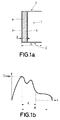
- Figure 1a shows an example of the spar of the state of the art.
- the distribution of shear stress borne by the adhesive bond between the spar and an inner surface of a longitudinal hollow element wherein said spar is disposed has been represented.
- the distribution of stress is such that two maximum stress peaks are generated. Said peaks correspond to the fibre fabric layers.
- the central core (4) of the spar (1) and the two fibre fabric layers (3) comprised by said spar (1) have been represented in said figure.
- the fibre fabric layers (3) are disposed covering the two lateral sides of the central core (4) and also compose the bonding zone (2) of the spar (1) that bonds with the inner side of the blade pressure and suction surfaces.
- the bonding zones (2) of the spar (1) are formed by a single central core (4) and by the two fibre fabric layers (3).
- the thickness (E) of the central core (4) and a first width (A), which is the width of the adhesive bond with the inner side of the blade pressure and suction surfaces for a spar (1) of the state of the art, are also indicated.
- Figure 1b shows a graph representing the shear stress generated in the adhesive bond. As described previously, two shear stress peaks appear.
- the present invention describes a wind turbine blade having a spar that ensures a more homogeneous distribution of the shear stress in the adhesive bond between the spar and the inner surface of the longitudinal hollow element.
- the blade comprises at least one longitudinal hollow element that defines an outer aerodynamic surface and an inner cavity having an inner surface having a pressure zone and a suction zone; and comprises at least one spar (1).
- Said spar (1) is disposed in the inner cavity and is joined to the inner surface by at least two bonding surfaces (13) disposed in the spar bonding zones (2).
- the spar (1) comprises at least three fibre fabric layers (3) and at least one central core (4) and at least one lateral core (5) disposed between the at least three fibre fabric layers (3), disposed in at least one bonding zone (2).
- the at least three fibre fabric layers (3) are disposed parallel therebetween and transversely or obliquely with respect to the bonding surface (13) in the bonding zone near the bonding surface.
- the at least three fibre fabric layers (3) extend between the spar bonding zones (2).
- each fibre fabric (3) layer is disposed on at least one side of the central core (4) or lateral core (5).
- FIG. 2 shows an embodiment wherein the spar (1) of a wind turbine blade of the present invention has been represented with a C-shaped configuration.
- a second width (B) which is the width of the bonding surface (13) of the C-shaped spar (1) of the present invention that bonds with the blade pressure and suction surfaces.
- Said second width (B) is smaller than the first width (A) of the spars of the state of the art.
- Figure 3a shows an embodiment wherein the spar (1) has a double T-shaped configuration.
- Figure 3b shows a graph representing the distribution of shear stress on the bonding surface (13) between the spars (1).
- the graph shows the stress experienced throughout a third width (C) which is the width of the bonding surface (13) of the spar (1) in this embodiment.
- C third width
- the shear stress is distributed more homogeneously and the value of the maximum shear stress peak has been reduced.
- the at least three layers of fibre fabric (3) are separated by at least two cores (4, 5) in the bonding zone (2) of the spar (1).
- Figure 4 shows the cores (4, 5) and fibre fabric layers (3) of the present invention.
- a zoom image of the bonding zone (2) is shown in order to represent the layout of the elements in this zone, which is the zone wherein the adhesive bond is executed, in detail.
- a central core (4) and a lateral core (5) disposed on both sides of the central core (4) in the bonding zone (2) can be observed.
- the geometry of said lateral cores (5) is such that, in the bonding zone (2), all the fibre fabric layers (3) are substantially parallel.
- the bonding surface (13), which is the surface of the spar (1) that is bonded to the inner surfaces of the longitudinal hollow element, has also been represented.
- the lateral core (5) comprises an adjacent side (14), at least one divergent side (7) that diverges from at least one of the lateral sides (6) of the central core (4) according to an angle of divergence (9).
- said divergence (9) is less than or equal to 60°.
- said angle of divergence (9) is less than or equal to 30°.
- said angle of divergence remains constant throughout the spar.
- the at least one central core (4) comprises at least two fibre fabric layers (3) disposed on at least part of one of the lateral sides (6).
- One of the fibre fabric layers (3) extends up to the bonding surface (13) directly on said lateral side (6) and the other fibre fabric layer (3) is also disposed on the divergent side (7) of the lateral core (5) such that at least two fibre fabric layers (3) are separated therebetween from the corresponding lateral side (6) up to the at least one bonding surface (13).
- the lateral core (5) also comprises a lateral surface (8) parallel to the lateral side (6) of the central core (4) and adjacent to the divergent side (7), which extends between the divergent side (7) and the bonding surface (13).
- one of the fibre fabric layers (3) extends up to the bonding surface (13) directly on the lateral side (6) of the central core and the other fibre fabric layer (3) is also disposed on the divergent side (7) of the lateral core (5) and on the parallel lateral surface (8), wherein the layer is prolonged up to the bonding surface.
- the layer disposed on the lateral side (6) of the central core (4) and the layer disposed on the parallel lateral surface (8) are disposed parallel therebetween in the bonding zone near said bonding surface (13).
- the cores (4) are made of foam, PVC or balsa wood.
- the bond between the spar (1) and the inner surface is executed by means of an adhesive bond.
- the spar (1) comprises four fibre fabric layers (3), a central core (4) and additionally comprises, in each spar bonding zone (2), two lateral cores (5) disposed in such a manner that in the bonding zone (2), each fibre fabric layer (3) is separated from the adjacent layer by a core (4, 5).
- This configuration makes it possible for the shear stress and width value of the bonding surface reached in this four-layer configuration to be less than in the configuration of the state of the art: ⁇ ' Max ⁇ Max and C ⁇ A, respectively, according to figures 1a and 1b and 3a and 3b .
- the width of the adhesive bond B is smaller than the width A of figure 1 as a consequence of a lower shear value in said bond.
- the lateral surface (8) of the lateral core (5) has a constant height throughout the entire section of the spar (1).
- the lateral cores (5) have a variable height throughout their length and said height varies in the same proportion as the height of the central core (4). This variation, preferably, decreases in height from the blade root zone to the blade tip zone.
- the central core (4) and the lateral cores (5) extend between the two bonding surfaces (13) in at least one zone of the blade.
- the thickness of the central core (4) is greater than the thickness of the lateral cores (5). In another embodiment, the thickness of the central core (4) decreases throughout the length of the spar (1) from the blade root zone to the blade tip zone and/or the thickness of the lateral cores (5) increases throughout the length of the spar (1) from the blade root zone to the blade tip zone.
- the width of the spar (1) which is the sum of the thicknesses of the central core (4) and of the lateral cores (5), is constant throughout its length.
- Figure 6 shows a blade and an embodiment wherein three sections are distinguished (10, 11, 12) wherein the thickness of the central core (4) differs while the width of the spar remains constant throughout its entire length.
- the thickness of the central core (4) is smaller the nearer the section to the blade tip zone and, in order to maintain a constant spar width, the thickness of the lateral cores (5) increases throughout the length of the spar (1) from the blade root zone to the blade tip zone.
- a first section (10) has been represented in the zone nearest the blade root, a second section (11) in the intermediate zone of the blade and a third section (12) in the zone of the blade tip.
- the central core (4) extends between the two bonding surfaces (13) and comprises two lateral cores (5), each of which disposed near the central core (4) in each bonding zone (2).
- the central core (4) extends between the two bonding surfaces (13) and comprises four lateral cores, two of which are disposed on the sides of the central core (4) in each bonding zone (2).
Landscapes
- Engineering & Computer Science (AREA)
- Life Sciences & Earth Sciences (AREA)
- Sustainable Development (AREA)
- Sustainable Energy (AREA)
- Chemical & Material Sciences (AREA)
- Combustion & Propulsion (AREA)
- Mechanical Engineering (AREA)
- General Engineering & Computer Science (AREA)
- Wind Motors (AREA)
Abstract
Description
- The present invention falls within the technical field of wind turbines. More specifically, it disclosed a wind turbine blade having an enhanced bond between the spar and inner surface of the blade.
- In general, wind turbine blades have a pressure surface and a suction surface consisting of laminated composite material joined therebetween and which confer the aerodynamic geometry to the blade. The connection of the pressure and suction surfaces is performed joining their ends and by means of spars disposed in the cavity formed by said pressure and suction surfaces. The spars stiffen the pressure and suction surfaces to avoid bending of the laminates that form them. The connection between the spars and pressure and suction surfaces can be executed in various manners, but the most common is bonding by means of adhesive.
- In some cases, the blades are formed by a continuous surface, there not existing a bond defined between the pressure and suction surfaces. Also in these cases, the spars stiffen said pressure and suction surfaces and the bond between those and these is usually executed by means of adhesive.
- The conventional geometry of the spars is I- or C-shaped, although spars having L- or T-shaped and even X- or K-shaped geometries are also known. The selection of one type of geometry or another depends on the structural requirements in terms of capacity to transmit the shear stress experienced by the blade due to aerodynamic loads and other solicitations arising during wind turbine operation. This shear stress is transmitted from the spars to the pressure and suction surfaces through the bond thereof which, as described previously, is usually an adhesive bond.
- The spars comprise:
- a central zone formed by at least one core and at least two fibre fabric layers disposed on both sides of the central core, and
- two bonding zones on both ends of the central zone formed by a continuation of the core fibres.
- Usually, the central zone of the spar is disposed substantially transversely or obliquely to the blade pressure and suction surfaces. The spar bonding zones allow adhesive bonding to the blade pressure and suction surfaces and comprise at least one bonding surface substantially parallel to said blade pressure and suction surfaces.
- In this manner, each fibre fabric layer of the core forms a shear stress transmission layer such that the spar usually comprises two layers. As the shear stress must be absorbed by the fibre fabric layers, the distribution of shear stress in the adhesive is not even, generating two shear stress tension peaks corresponding to each of the fibre fabric layers.
- This makes it necessary, when using spars having a C-shaped geometry, to increase the width of the bond for the purpose of reducing the tension borne by the adhesive. However, this increase in width implies an increased in the use of adhesive material.
- The present invention describes a wind turbine blade having at least one spar configured to enhance the adhesive bonding thereof to the inner surface of the longitudinal hollow element of the blade. The spar makes it possible, due to a more homogeneous distribution of shear stress in said bond, to reduce the width of said adhesive bond and enhance the transfer of shear stress between the inner surface of the longitudinal hollow element and the spar itself. This in turn makes it possible to use less adhesive material.
- Therefore, the blade of the present invention makes it possible to even out the distribution of shear stress in the adhesive bonding zone between the inner surface of the longitudinal hollow element and the spar, minimising in turn the peak values of said stress.
- The proposed blade comprises at least one longitudinal hollow element that defines an aerodynamic outer surface with a pressure zone and a suction zone, and an inner cavity having an inner surface which, in turn, has a zone corresponding to the pressure zone and a zone corresponding to the suction zone. And the blade comprises at least one spar disposed in the inner cavity and joined to the inner surface by at least two bonding surfaces disposed in the spar bonding zones.
- In order to achieve the described objectives, the spar of the blade of the present invention comprises, in the spar bonding zones, which are preferably joined to the inner surface by means of an adhesive bond, a larger number of fibre fabric layers than the spars of the state of the art (it comprises at least three layers compared to two layers in the spars of the state of the art), separated therebetween by cores.
- The fibre fabric layers which form the spar stress transmission layers that transmit stress to the inner surface of the longitudinal hollow element are disposed parallel therebetween and transversely or obliquely with respect to the inner surfaces in the blade suction and pressure zones.
- Although a larger number of fibre fabric layers and cores increases the number of shear tension peaks in the adhesive bond, the maximum values of these peaks are lower than with a smaller number of layers.
- In this manner, enhanced transfer of the shear stress between the inner surface and the spars is achieved and the maximum shear stress magnitude in the bond is reduced with respect to the state of the art. The amount of fibre fabric used, which has a higher cost and density than the cores, is also optimised, and the width of the adhesive bond required to adequately transmit the stress is reduced.
- In the blade described, the spar has, in the adhesive bonding zone, at least three fibre fabric layers and a group of cores having at least two cores. The layout of the fibre layers with respect to the cores may depend on the loads of the blade in accordance with the type of wind to be supported, where it is installed, etc. This spar configuration allows a more even distribution of the stress in the adhesive bond between the spar and the inner surface of the longitudinal hollow element of the blade.
- Specifically, the at least one spar of the blade described comprises, in the adhesive bonding zone, a number of fibre fabric layers (i.e. shear stress transmission layers) equal to or greater than three. Said at least three layers are separated by at least two cores in the bonding zone of the spar to the blade pressure and suction surfaces.
- With respect to another type of spars known in the state of the art, in the bonding zone each of the cores of the present invention is disposed between at least two fibre fabric layers.
- As already described, this configuration makes it possible to reduce the maximum shear stress magnitude in the bond between the spars and the blade pressure and suction surfaces. This also results in a reduction in the width of the spar in the bonding zone (the bonding surface of the spar is reduced), making it possible to save a large amount of adhesive and avoid the use of additional bonding and reinforcement elements external to the spar itself.
- Therefore, each spar comprises a central core and at least one lateral core. The geometry of the lateral cores is such that, in the bonding zone, all the fibre fabric layers (i.e. all the stress transmission layers) are substantially parallel.
- The at least one lateral core comprises an adjacent side, at least one side divergent with respect to, at least, one lateral side of the central core according to an angle of divergence.
- The angle of divergence between the lateral surface of the lateral core and the lateral surface of the central core is less than or equal to 60°, preferably less than or equal to 30°. In a preferred embodiment, said angle of divergence remains constant throughout the spar.
- The at least one lateral core also comprises a lateral surface parallel to the lateral side of the central core and adjacent to the divergent side of the lateral core that extends between the divergent side and the bonding zone.
- In one embodiment, the spar has four layers such as to comprise a central core and two lateral cores on each side of the spar bonding zone. In said bonding zone, each layer is separated from the adjacent layer by at least one core.
- In one embodiment, the height of the spars varies from the zone next to the blade root, where they are higher, to the zone nearest the blade tip, where they are lower.
- In one embodiment, the height of the lateral surface parallel to the lateral core in the zone opposite the central core is constant throughout the blade.
- The height of the lateral cores is less than the height of the central core, in at least one zone of the spar, said zone being disposed near the blade root.
- In one embodiment, the thickness of the central core is greater than the thickness of the lateral cores.
- The thickness of the central core decreases throughout the length of the spar from the zone near the blade root towards the zone nearest the blade tip, where it is less thick. Likewise, the height of the spars varies from the zone near the blade root, where they are higher, to the zone nearest the blade tip, where they have thinner aerodynamic profiles and, therefore, the spars are lower in height.
- Also, the thickness of the lateral cores increases throughout the length of the spar, from the zone near the blade root towards the zone nearest the blade tip.
- In addition, according to this embodiment, the thickness of the central core and of the lateral cores is such that the total length of the spar, which is the sum of the thicknesses of the central core and of the lateral cores, is constant throughout the entire length of the spar. This facilitates the blade manufacturing process and increases reliability, as it allows the distance between the adhesive lines of the adhesive bond to be constant throughout the entire length of the blade.
- Each fibre fabric layer may be formed by one or more layers of fibre fabric, said fibre fabrics having different surface fibre content densities.
- In one embodiment, the spar is composed of a central zone and two bonding zones comprising four layers disposed parallel therebetween and obliquely with respect to the inner blade surface. Each of the layers is separated from the adjacent layer in said bonding zone by at least one core (made of PVC in one embodiment). Specifically, the central layers are separated therebetween by a central core and each layer is separated from the respective outer layers by a lateral core.
- According to a particular embodiment wherein the number of layers is four, with two lateral layers and two central layers, the central layers comprise a greater number of fibre fabric layers than the lateral layers. In a preferred embodiment, in turn, the surface density of the fibre content in said fabric layers. According to one embodiment, the central layers comprise three fibre fabric layers of a density 50% greater than the fabric layers of the lateral layers.
- In one embodiment, the height of the lateral layers in at least one spar zone is substantially equal to the height of the central core.
- In a preferred embodiment, the blade has two spars, a main spar disposed near a zone of the leading edge and a spar disposed near the zone of the trailing edge of the blade and, therefore, generally lower in height than the main spar.
- In order to complement the description being made and with the aim of helping to better understand the characteristics of the invention, in accordance with a preferred embodiment thereof, said description is accompanied, as an integral part thereof, by a set of drawings where, in an illustrative and non-limiting manner, the following has been represented:
-
Figure 1a shows a view of a spar of the state of the art having a C-shaped configuration; -
Figure 1b shows a graph representing the distribution of shear stress in the spar offigure 1 a; -
Figure 2 shows a view of a spar of the wind turbine blade of the present invention having a C-shaped configuration; -
Figure 3a shows a view of a spar of the wind turbine blade of the present invention having a double T-shaped configuration; -
Figure 3b shows a graph representing the distribution of shear stress in the spar offigure 3a ; -
Figure 4 shows a view wherein the cores and fibre layers of the spar of the blade of the present invention can be observed; -
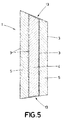
Figure 5 shows a view of the spar in the blade tip zone; and -
Figure 6 shows a profile view of a blade wherein the different zones of the blade wherein the thickness of the central core differs are indicated. - Following is a description, with the help of
figures 1 to 6 , of embodiments of the present invention. -
Figure 1a shows an example of the spar of the state of the art. In said figure the distribution of shear stress borne by the adhesive bond between the spar and an inner surface of a longitudinal hollow element wherein said spar is disposed has been represented. As described previously, the distribution of stress is such that two maximum stress peaks are generated. Said peaks correspond to the fibre fabric layers. - The central core (4) of the spar (1) and the two fibre fabric layers (3) comprised by said spar (1) have been represented in said figure. As can be observed in the figure, the fibre fabric layers (3) are disposed covering the two lateral sides of the central core (4) and also compose the bonding zone (2) of the spar (1) that bonds with the inner side of the blade pressure and suction surfaces. As can be observed in the figure, the bonding zones (2) of the spar (1) are formed by a single central core (4) and by the two fibre fabric layers (3). The thickness (E) of the central core (4) and a first width (A), which is the width of the adhesive bond with the inner side of the blade pressure and suction surfaces for a spar (1) of the state of the art, are also indicated.
Figure 1b shows a graph representing the shear stress generated in the adhesive bond. As described previously, two shear stress peaks appear. - The present invention describes a wind turbine blade having a spar that ensures a more homogeneous distribution of the shear stress in the adhesive bond between the spar and the inner surface of the longitudinal hollow element.
- The blade comprises at least one longitudinal hollow element that defines an outer aerodynamic surface and an inner cavity having an inner surface having a pressure zone and a suction zone; and comprises at least one spar (1). Said spar (1) is disposed in the inner cavity and is joined to the inner surface by at least two bonding surfaces (13) disposed in the spar bonding zones (2).
- The key of the present invention is that the spar (1) comprises at least three fibre fabric layers (3) and at least one central core (4) and at least one lateral core (5) disposed between the at least three fibre fabric layers (3), disposed in at least one bonding zone (2).
- In one embodiment, the at least three fibre fabric layers (3) are disposed parallel therebetween and transversely or obliquely with respect to the bonding surface (13) in the bonding zone near the bonding surface.
- In one embodiment, the at least three fibre fabric layers (3) extend between the spar bonding zones (2).
- In one embodiment, each fibre fabric (3) layer is disposed on at least one side of the central core (4) or lateral core (5).
-
Figure 2 shows an embodiment wherein the spar (1) of a wind turbine blade of the present invention has been represented with a C-shaped configuration. In said figure, a second width (B), which is the width of the bonding surface (13) of the C-shaped spar (1) of the present invention that bonds with the blade pressure and suction surfaces, is indicated. Said second width (B) is smaller than the first width (A) of the spars of the state of the art. This reduction in the width of the bonding surface (13) of the spar (1) makes it possible to save on adhesive and, due to the distribution of the stress, the use of additional bonding elements or reinforcement elements external to the spar itself are not required. -
Figure 3a shows an embodiment wherein the spar (1) has a double T-shaped configuration.Figure 3b shows a graph representing the distribution of shear stress on the bonding surface (13) between the spars (1). The graph shows the stress experienced throughout a third width (C) which is the width of the bonding surface (13) of the spar (1) in this embodiment. As can be seen in graph 3b, in comparison with the graph offigure 1b , the shear stress is distributed more homogeneously and the value of the maximum shear stress peak has been reduced. - The at least three layers of fibre fabric (3) are separated by at least two cores (4, 5) in the bonding zone (2) of the spar (1).
-
Figure 4 shows the cores (4, 5) and fibre fabric layers (3) of the present invention. In this case, a zoom image of the bonding zone (2) is shown in order to represent the layout of the elements in this zone, which is the zone wherein the adhesive bond is executed, in detail. In this embodiment, a central core (4) and a lateral core (5) disposed on both sides of the central core (4) in the bonding zone (2) can be observed. The geometry of said lateral cores (5) is such that, in the bonding zone (2), all the fibre fabric layers (3) are substantially parallel. The bonding surface (13), which is the surface of the spar (1) that is bonded to the inner surfaces of the longitudinal hollow element, has also been represented. - In one example of embodiment, such as that shown in
figure 4 , the lateral core (5) comprises an adjacent side (14), at least one divergent side (7) that diverges from at least one of the lateral sides (6) of the central core (4) according to an angle of divergence (9). In one example of embodiment, said divergence (9) is less than or equal to 60°. Preferably, said angle of divergence (9) is less than or equal to 30°. In one embodiment, said angle of divergence remains constant throughout the spar. - Likewise, the at least one central core (4) comprises at least two fibre fabric layers (3) disposed on at least part of one of the lateral sides (6). One of the fibre fabric layers (3) extends up to the bonding surface (13) directly on said lateral side (6) and the other fibre fabric layer (3) is also disposed on the divergent side (7) of the lateral core (5) such that at least two fibre fabric layers (3) are separated therebetween from the corresponding lateral side (6) up to the at least one bonding surface (13).
- In one embodiment, the lateral core (5) also comprises a lateral surface (8) parallel to the lateral side (6) of the central core (4) and adjacent to the divergent side (7), which extends between the divergent side (7) and the bonding surface (13). Thus, according to this embodiment, one of the fibre fabric layers (3) extends up to the bonding surface (13) directly on the lateral side (6) of the central core and the other fibre fabric layer (3) is also disposed on the divergent side (7) of the lateral core (5) and on the parallel lateral surface (8), wherein the layer is prolonged up to the bonding surface. In this manner, the layer disposed on the lateral side (6) of the central core (4) and the layer disposed on the parallel lateral surface (8) are disposed parallel therebetween in the bonding zone near said bonding surface (13).
- Preferably, the cores (4) are made of foam, PVC or balsa wood. Also preferably, the bond between the spar (1) and the inner surface is executed by means of an adhesive bond.
- In the example of embodiment shown in
figure 4 , the spar (1) comprises four fibre fabric layers (3), a central core (4) and additionally comprises, in each spar bonding zone (2), two lateral cores (5) disposed in such a manner that in the bonding zone (2), each fibre fabric layer (3) is separated from the adjacent layer by a core (4, 5). This configuration makes it possible for the shear stress and width value of the bonding surface reached in this four-layer configuration to be less than in the configuration of the state of the art: τ'Max<τMax and C < A, respectively, according tofigures 1a and 1b and3a and 3b . This is also the case of the three-layer configuration offigure 2 , the width of the adhesive bond B is smaller than the width A offigure 1 as a consequence of a lower shear value in said bond. - In one embodiment, at least the lateral surface (8) of the lateral core (5) has a constant height throughout the entire section of the spar (1). In another embodiment, such as that shown in
figure 5 , the lateral cores (5) have a variable height throughout their length and said height varies in the same proportion as the height of the central core (4). This variation, preferably, decreases in height from the blade root zone to the blade tip zone. In one embodiment, the central core (4) and the lateral cores (5) extend between the two bonding surfaces (13) in at least one zone of the blade. - In one embodiment, the thickness of the central core (4) is greater than the thickness of the lateral cores (5). In another embodiment, the thickness of the central core (4) decreases throughout the length of the spar (1) from the blade root zone to the blade tip zone and/or the thickness of the lateral cores (5) increases throughout the length of the spar (1) from the blade root zone to the blade tip zone.
- Preferably, the width of the spar (1), which is the sum of the thicknesses of the central core (4) and of the lateral cores (5), is constant throughout its length.
-
Figure 6 shows a blade and an embodiment wherein three sections are distinguished (10, 11, 12) wherein the thickness of the central core (4) differs while the width of the spar remains constant throughout its entire length. In this case, the thickness of the central core (4) is smaller the nearer the section to the blade tip zone and, in order to maintain a constant spar width, the thickness of the lateral cores (5) increases throughout the length of the spar (1) from the blade root zone to the blade tip zone. In the figure, a first section (10) has been represented in the zone nearest the blade root, a second section (11) in the intermediate zone of the blade and a third section (12) in the zone of the blade tip. - In one embodiment, as shown in
figure 2 , the central core (4) extends between the two bonding surfaces (13) and comprises two lateral cores (5), each of which disposed near the central core (4) in each bonding zone (2). In another embodiment, as shown infigure 3a , the central core (4) extends between the two bonding surfaces (13) and comprises four lateral cores, two of which are disposed on the sides of the central core (4) in each bonding zone (2).
Claims (18)
- A wind turbine blade comprising:- at least one longitudinal hollow element that defines:- an external aerodynamic surface, and- an inner cavity having an inner surface in which there are a pressure zone and a suction zone,- at least one spar (1), disposed in the inner cavity and bonded to the inner surface in at least two bonding surfaces (13) disposed in bonding zones (2) of the spar (1),and is characterised in that the spar (1) comprises, in at least one bonding zone (2):- at least three fibre fabric layers (3), and- at least one central core (4) and at least one lateral core (5) disposed between the at least three fibre fabric layers (3).
- The wind turbine blade, according to claim 1, wherein at least three fibre fabric layers are disposed parallel therebetween and transversely or obliquely with respect to the bonding surface (13).
- The wind turbine blade, according to claim 1, characterised in that the at least three fibre fabric layers (3) extend between the bonding zones (2) of the spar.
- The wind turbine blade, according to claim 1, characterised in that each fibre fabric layer (3) is disposed over at least one side of the central core (4) or of the lateral core (5).
- The wind turbine blade, according to claim 1, characterised in that the bond between the bonding surface (13) of the spar (1) and the inner surface is executed by means of an adhesive bond.
- The wind turbine blade, according to claim 1, characterised in that:- the at least one lateral core (5) comprises an adjacent side (14) and at least one divergent side (7) with respect to, at least, one lateral side (6) of the at least one central core (4) according to an angle of divergence (9),- the at least one central core (4) comprises at least two fibre fabric layers (3) disposed on at least part of one of the lateral sides (6), wherein one of the fibre fabric layers (3) extends up to the bonding surface (13) directly on said lateral side (6) and another of the fibre fabric layers (3) is disposed on the divergent side (7) of the lateral core (5), such that the at least two fibre fabric layers (3) are separated therebetween from the corresponding lateral side (6) of the central core (4) up to the at least one bonding surface (13).
- The wind turbine blade, according to claim 6, characterised in that the angle of divergence (9) is less than or equal to 60°.
- The wind turbine blade, according to claim 6, characterised in that the angle of divergence (9) is less than or equal to 30°.
- The wind turbine blade, according to claims 6 to 8, characterised in that the lateral core (5) also comprises a lateral surface (8) parallel to the lateral side (6) of the central core (4) and adjacent to the divergent side (7).
- The wind turbine blade, according to claim 9, characterised in that the lateral surface (8) of the lateral core (5) has a constant height throughout the entire spar (1).
- The wind turbine blade, according to claim 1, characterised in that the spar (1) comprises four fibre fabric layers (3), one central core (4) and, in each spar bonding zone (2), two lateral cores (5) disposed such that in the bonding surface (2) each fibre fabric layer (3) is separated from the adjacent layer by a lateral core (5).
- The wind turbine blade, according to claim 1, characterised in that the thickness of at least one central core (4) is greater than the thickness of at least one lateral core (5).
- The wind turbine blade, according to claim 1, characterised in that the thickness of the central core (4) decreases throughout the length of the spar (1) from the blade root zone to the blade tip zone.
- The wind turbine blade, according to claim 1, characterised in that the thickness of the lateral cores (5) increases throughout the length of the spar (1) from the blade root zone to the blade tip zone.
- The wind turbine blade, according to claims 13 and 14, characterised in that the width of the spar (1), which is the sum of the thicknesses of the central core (4) and of the lateral cores (5), is constant throughout its length.
- The wind turbine blade, according to claim 1, characterised in that the central core (4) extends between the two bonding surfaces (13) comprises two lateral cores (5), each of which is disposed next to the central core (4) in each bonding zone (2).
- The wind turbine blade, according to claim 1, characterised in that the central core (4) extends between the two bonding surfaces (13) and comprises four lateral cores, two of which are disposed on the sides of the central core (4) in each bonding zone (2).
- The wind turbine blade, according to claim 1, characterised in that the central core (4) and lateral cores (5) extend between the two bonding surfaces (13) in at least one blade zone.
Priority Applications (6)
| Application Number | Priority Date | Filing Date | Title |
|---|---|---|---|
| DK15382547.6T DK3165762T3 (en) | 2015-11-06 | 2015-11-06 | WINDMILL ROTOR BLADE |
| PL15382547.6T PL3165762T3 (en) | 2015-11-06 | 2015-11-06 | Wind turbine blade |
| ES15382547T ES2973100T3 (en) | 2015-11-06 | 2015-11-06 | wind turbine blade |
| EP15382547.6A EP3165762B1 (en) | 2015-11-06 | 2015-11-06 | Wind turbine blade |
| PT153825476T PT3165762T (en) | 2015-11-06 | 2015-11-06 | Wind turbine blade |
| US15/353,191 US10502180B2 (en) | 2015-11-06 | 2016-11-16 | Blade for a wind turbine |
Applications Claiming Priority (1)
| Application Number | Priority Date | Filing Date | Title |
|---|---|---|---|
| EP15382547.6A EP3165762B1 (en) | 2015-11-06 | 2015-11-06 | Wind turbine blade |
Publications (2)
| Publication Number | Publication Date |
|---|---|
| EP3165762A1 true EP3165762A1 (en) | 2017-05-10 |
| EP3165762B1 EP3165762B1 (en) | 2023-12-27 |
Family
ID=55024042
Family Applications (1)
| Application Number | Title | Priority Date | Filing Date |
|---|---|---|---|
| EP15382547.6A Active EP3165762B1 (en) | 2015-11-06 | 2015-11-06 | Wind turbine blade |
Country Status (6)
| Country | Link |
|---|---|
| US (1) | US10502180B2 (en) |
| EP (1) | EP3165762B1 (en) |
| DK (1) | DK3165762T3 (en) |
| ES (1) | ES2973100T3 (en) |
| PL (1) | PL3165762T3 (en) |
| PT (1) | PT3165762T (en) |
Cited By (1)
| Publication number | Priority date | Publication date | Assignee | Title |
|---|---|---|---|---|
| EP3885573A1 (en) | 2020-03-27 | 2021-09-29 | Nordex Energy SE & Co. KG | Bar for reinforcing a wind energy system rotor blade |
Families Citing this family (1)
| Publication number | Priority date | Publication date | Assignee | Title |
|---|---|---|---|---|
| WO2020119870A1 (en) * | 2018-12-10 | 2020-06-18 | Vestas Wind Systems A/S | Improvements relating to wind turbine blade manufacture |
Citations (6)
| Publication number | Priority date | Publication date | Assignee | Title |
|---|---|---|---|---|
| US20140064980A1 (en) * | 2012-08-30 | 2014-03-06 | General Electric Company | Rotor blades with infused prefabricated shear webs and methods for making the same |
| EP2716904A1 (en) * | 2012-10-04 | 2014-04-09 | Areva Blades GmbH | Composite spar cap for a rotor blade of a wind turbine and method of manufacturing the composite spar cap |
| EP2778393A2 (en) * | 2013-03-15 | 2014-09-17 | Vestas Wind Systems A/S | Wind turbine blade design and associated manufacturing methods using rectangular spars |
| US20140348659A1 (en) * | 2013-05-22 | 2014-11-27 | General Electric Company | Wind turbine rotor blade assembly having reinforcement assembly |
| EP2808157A1 (en) * | 2013-05-29 | 2014-12-03 | Siemens Aktiengesellschaft | Wind turbine blade and method of fabricating a wind turbine blade |
| EP2843227A1 (en) * | 2013-08-28 | 2015-03-04 | General Electric Company | Method for installing a shear web insert within a segmented rotor blade assembly |
Family Cites Families (8)
| Publication number | Priority date | Publication date | Assignee | Title |
|---|---|---|---|---|
| US6849150B1 (en) * | 2001-01-16 | 2005-02-01 | Lockheed Martin Corporation | System and method of forming structural assemblies with 3-D woven joint pre-forms |
| CN102022254B (en) * | 2009-09-23 | 2014-12-17 | 固瑞特模具(太仓)有限公司 | Wind turbine blade and manufacturing method thereof |
| DE102010003114A1 (en) * | 2010-03-22 | 2011-09-22 | Repower Systems Ag | web connection |
| US20130315747A1 (en) * | 2012-05-23 | 2013-11-28 | Karsten Schibsbye | Wind turbine blade with improved geometry for reinforcing fibers |
| EP2881237B1 (en) * | 2013-12-03 | 2019-06-26 | LM WP Patent Holding A/S | A method of manufacturing a shear web using a pre-formed web foot flange |
| CN107107487B (en) * | 2014-10-30 | 2019-07-30 | Lm Wp 专利控股有限公司 | Fabrication of I-Shaped Shear Webs |
| US10422315B2 (en) * | 2015-09-01 | 2019-09-24 | General Electric Company | Pultruded components for a shear web of a wind turbine rotor blade |
| US10533534B2 (en) * | 2015-09-09 | 2020-01-14 | General Electric Company | Composite layers for bonding components of a wind turbine rotor blade |
-
2015
- 2015-11-06 PT PT153825476T patent/PT3165762T/en unknown
- 2015-11-06 PL PL15382547.6T patent/PL3165762T3/en unknown
- 2015-11-06 ES ES15382547T patent/ES2973100T3/en active Active
- 2015-11-06 DK DK15382547.6T patent/DK3165762T3/en active
- 2015-11-06 EP EP15382547.6A patent/EP3165762B1/en active Active
-
2016
- 2016-11-16 US US15/353,191 patent/US10502180B2/en active Active
Patent Citations (6)
| Publication number | Priority date | Publication date | Assignee | Title |
|---|---|---|---|---|
| US20140064980A1 (en) * | 2012-08-30 | 2014-03-06 | General Electric Company | Rotor blades with infused prefabricated shear webs and methods for making the same |
| EP2716904A1 (en) * | 2012-10-04 | 2014-04-09 | Areva Blades GmbH | Composite spar cap for a rotor blade of a wind turbine and method of manufacturing the composite spar cap |
| EP2778393A2 (en) * | 2013-03-15 | 2014-09-17 | Vestas Wind Systems A/S | Wind turbine blade design and associated manufacturing methods using rectangular spars |
| US20140348659A1 (en) * | 2013-05-22 | 2014-11-27 | General Electric Company | Wind turbine rotor blade assembly having reinforcement assembly |
| EP2808157A1 (en) * | 2013-05-29 | 2014-12-03 | Siemens Aktiengesellschaft | Wind turbine blade and method of fabricating a wind turbine blade |
| EP2843227A1 (en) * | 2013-08-28 | 2015-03-04 | General Electric Company | Method for installing a shear web insert within a segmented rotor blade assembly |
Cited By (2)
| Publication number | Priority date | Publication date | Assignee | Title |
|---|---|---|---|---|
| EP3885573A1 (en) | 2020-03-27 | 2021-09-29 | Nordex Energy SE & Co. KG | Bar for reinforcing a wind energy system rotor blade |
| US11466661B2 (en) | 2020-03-27 | 2022-10-11 | Nordex Energy Se & Co. Kg | Shear web for stiffening a wind turbine rotor blade |
Also Published As
| Publication number | Publication date |
|---|---|
| DK3165762T3 (en) | 2024-03-04 |
| US10502180B2 (en) | 2019-12-10 |
| ES2973100T3 (en) | 2024-06-18 |
| US20170234295A1 (en) | 2017-08-17 |
| PT3165762T (en) | 2024-03-22 |
| EP3165762B1 (en) | 2023-12-27 |
| PL3165762T3 (en) | 2024-05-06 |
Similar Documents
| Publication | Publication Date | Title |
|---|---|---|
| EP2971756B1 (en) | Wind turbine blades with layered, multi-component spars, and associated systems | |
| JP6177611B2 (en) | Bending and reinforcing members of laminated composites reinforced with mutual thin plate metal sheets | |
| US8079819B2 (en) | Optimization of premium fiber material usage in wind turbine spars | |
| RU2420407C2 (en) | Thin-layer laminates | |
| JP5898175B2 (en) | Method for producing composite longitudinal stringer and composite longitudinal stringer | |
| US20120263913A1 (en) | Wing and blade structure using pultruded composites | |
| EP2778393A2 (en) | Wind turbine blade design and associated manufacturing methods using rectangular spars | |
| CN102186722B (en) | Structural element for reinforcing a fuselage of an aircraft | |
| EP3802091B1 (en) | Wind turbine blade spar structure and method of manufacturing | |
| EP4339451B1 (en) | Connection structure for wind turbine blade segments | |
| EP2651759B1 (en) | Skew-angle radius filler to reduce the risk of delamination of a laminated stringer assembly | |
| US9764805B2 (en) | Board | |
| CN104129495A (en) | Composite structure for an aircraft and manufacturing method thereof | |
| US20110052404A1 (en) | Swept blades with enhanced twist response | |
| US10502180B2 (en) | Blade for a wind turbine | |
| CN101711212A (en) | Fibre metal laminate panel | |
| US12503996B2 (en) | Wind turbine blade with leeward reinforcement structures and windward reinforcement structures | |
| KR101375265B1 (en) | Blade for wind turbine and method for manufacturing the same | |
| US20110155852A1 (en) | Stiffening element for an aircraft and a surface structure with a stiffening element of this type | |
| US11415101B2 (en) | Rotor blade, method for manufacturing a rotor blade for a wind energy installation, and a wind energy installation | |
| GB2629782A (en) | A spar for a wind turbine blade | |
| EP4067066B1 (en) | Junction structure and method for manufacturing junction structure | |
| US20240295210A1 (en) | A blade for a wind turbine | |
| EP4461952A1 (en) | Spar cap, wind turbine blade as well as method of manufacturing a spar cap | |
| EP4077914B1 (en) | Wind turbine blade |
Legal Events
| Date | Code | Title | Description |
|---|---|---|---|
| PUAI | Public reference made under article 153(3) epc to a published international application that has entered the european phase |
Free format text: ORIGINAL CODE: 0009012 |
|
| STAA | Information on the status of an ep patent application or granted ep patent |
Free format text: STATUS: THE APPLICATION HAS BEEN PUBLISHED |
|
| AK | Designated contracting states |
Kind code of ref document: A1 Designated state(s): AL AT BE BG CH CY CZ DE DK EE ES FI FR GB GR HR HU IE IS IT LI LT LU LV MC MK MT NL NO PL PT RO RS SE SI SK SM TR |
|
| AX | Request for extension of the european patent |
Extension state: BA ME |
|
| STAA | Information on the status of an ep patent application or granted ep patent |
Free format text: STATUS: REQUEST FOR EXAMINATION WAS MADE |
|
| 17P | Request for examination filed |
Effective date: 20171108 |
|
| RBV | Designated contracting states (corrected) |
Designated state(s): AL AT BE BG CH CY CZ DE DK EE ES FI FR GB GR HR HU IE IS IT LI LT LU LV MC MK MT NL NO PL PT RO RS SE SI SK SM TR |
|
| STAA | Information on the status of an ep patent application or granted ep patent |
Free format text: STATUS: EXAMINATION IS IN PROGRESS |
|
| 17Q | First examination report despatched |
Effective date: 20180518 |
|
| RAP1 | Party data changed (applicant data changed or rights of an application transferred) |
Owner name: NORDEX ENERGY SPAIN, S.A. |
|
| GRAP | Despatch of communication of intention to grant a patent |
Free format text: ORIGINAL CODE: EPIDOSNIGR1 |
|
| STAA | Information on the status of an ep patent application or granted ep patent |
Free format text: STATUS: GRANT OF PATENT IS INTENDED |
|
| P01 | Opt-out of the competence of the unified patent court (upc) registered |
Effective date: 20230529 |
|
| RIC1 | Information provided on ipc code assigned before grant |
Ipc: F03D 1/06 20060101AFI20230612BHEP |
|
| INTG | Intention to grant announced |
Effective date: 20230705 |
|
| RAP3 | Party data changed (applicant data changed or rights of an application transferred) |
Owner name: NORDEX ENERGY SPAIN, S.A. |
|
| GRAS | Grant fee paid |
Free format text: ORIGINAL CODE: EPIDOSNIGR3 |
|
| GRAA | (expected) grant |
Free format text: ORIGINAL CODE: 0009210 |
|
| STAA | Information on the status of an ep patent application or granted ep patent |
Free format text: STATUS: THE PATENT HAS BEEN GRANTED |
|
| AK | Designated contracting states |
Kind code of ref document: B1 Designated state(s): AL AT BE BG CH CY CZ DE DK EE ES FI FR GB GR HR HU IE IS IT LI LT LU LV MC MK MT NL NO PL PT RO RS SE SI SK SM TR |
|
| REG | Reference to a national code |
Ref country code: GB Ref legal event code: FG4D |
|
| REG | Reference to a national code |
Ref country code: CH Ref legal event code: EP |
|
| REG | Reference to a national code |
Ref country code: DE Ref legal event code: R096 Ref document number: 602015087069 Country of ref document: DE |
|
| REG | Reference to a national code |
Ref country code: IE Ref legal event code: FG4D |
|
| REG | Reference to a national code |
Ref country code: DK Ref legal event code: T3 Effective date: 20240229 |
|
| REG | Reference to a national code |
Ref country code: PT Ref legal event code: SC4A Ref document number: 3165762 Country of ref document: PT Date of ref document: 20240322 Kind code of ref document: T Free format text: AVAILABILITY OF NATIONAL TRANSLATION Effective date: 20240319 |
|
| PG25 | Lapsed in a contracting state [announced via postgrant information from national office to epo] |
Ref country code: GR Free format text: LAPSE BECAUSE OF FAILURE TO SUBMIT A TRANSLATION OF THE DESCRIPTION OR TO PAY THE FEE WITHIN THE PRESCRIBED TIME-LIMIT Effective date: 20240328 |
|
| REG | Reference to a national code |
Ref country code: LT Ref legal event code: MG9D |
|
| PG25 | Lapsed in a contracting state [announced via postgrant information from national office to epo] |
Ref country code: LT Free format text: LAPSE BECAUSE OF FAILURE TO SUBMIT A TRANSLATION OF THE DESCRIPTION OR TO PAY THE FEE WITHIN THE PRESCRIBED TIME-LIMIT Effective date: 20231227 |
|
| PG25 | Lapsed in a contracting state [announced via postgrant information from national office to epo] |
Ref country code: LT Free format text: LAPSE BECAUSE OF FAILURE TO SUBMIT A TRANSLATION OF THE DESCRIPTION OR TO PAY THE FEE WITHIN THE PRESCRIBED TIME-LIMIT Effective date: 20231227 Ref country code: GR Free format text: LAPSE BECAUSE OF FAILURE TO SUBMIT A TRANSLATION OF THE DESCRIPTION OR TO PAY THE FEE WITHIN THE PRESCRIBED TIME-LIMIT Effective date: 20240328 Ref country code: FI Free format text: LAPSE BECAUSE OF FAILURE TO SUBMIT A TRANSLATION OF THE DESCRIPTION OR TO PAY THE FEE WITHIN THE PRESCRIBED TIME-LIMIT Effective date: 20231227 Ref country code: BG Free format text: LAPSE BECAUSE OF FAILURE TO SUBMIT A TRANSLATION OF THE DESCRIPTION OR TO PAY THE FEE WITHIN THE PRESCRIBED TIME-LIMIT Effective date: 20240327 |
|
| REG | Reference to a national code |
Ref country code: NL Ref legal event code: MP Effective date: 20231227 |
|
| REG | Reference to a national code |
Ref country code: AT Ref legal event code: MK05 Ref document number: 1644746 Country of ref document: AT Kind code of ref document: T Effective date: 20231227 |
|
| PG25 | Lapsed in a contracting state [announced via postgrant information from national office to epo] |
Ref country code: NL Free format text: LAPSE BECAUSE OF FAILURE TO SUBMIT A TRANSLATION OF THE DESCRIPTION OR TO PAY THE FEE WITHIN THE PRESCRIBED TIME-LIMIT Effective date: 20231227 |
|
| PG25 | Lapsed in a contracting state [announced via postgrant information from national office to epo] |
Ref country code: SE Free format text: LAPSE BECAUSE OF FAILURE TO SUBMIT A TRANSLATION OF THE DESCRIPTION OR TO PAY THE FEE WITHIN THE PRESCRIBED TIME-LIMIT Effective date: 20231227 Ref country code: RS Free format text: LAPSE BECAUSE OF FAILURE TO SUBMIT A TRANSLATION OF THE DESCRIPTION OR TO PAY THE FEE WITHIN THE PRESCRIBED TIME-LIMIT Effective date: 20231227 Ref country code: NO Free format text: LAPSE BECAUSE OF FAILURE TO SUBMIT A TRANSLATION OF THE DESCRIPTION OR TO PAY THE FEE WITHIN THE PRESCRIBED TIME-LIMIT Effective date: 20240327 Ref country code: NL Free format text: LAPSE BECAUSE OF FAILURE TO SUBMIT A TRANSLATION OF THE DESCRIPTION OR TO PAY THE FEE WITHIN THE PRESCRIBED TIME-LIMIT Effective date: 20231227 Ref country code: LV Free format text: LAPSE BECAUSE OF FAILURE TO SUBMIT A TRANSLATION OF THE DESCRIPTION OR TO PAY THE FEE WITHIN THE PRESCRIBED TIME-LIMIT Effective date: 20231227 Ref country code: HR Free format text: LAPSE BECAUSE OF FAILURE TO SUBMIT A TRANSLATION OF THE DESCRIPTION OR TO PAY THE FEE WITHIN THE PRESCRIBED TIME-LIMIT Effective date: 20231227 |
|
| REG | Reference to a national code |
Ref country code: ES Ref legal event code: FG2A Ref document number: 2973100 Country of ref document: ES Kind code of ref document: T3 Effective date: 20240618 |
|
| PG25 | Lapsed in a contracting state [announced via postgrant information from national office to epo] |
Ref country code: IS Free format text: LAPSE BECAUSE OF FAILURE TO SUBMIT A TRANSLATION OF THE DESCRIPTION OR TO PAY THE FEE WITHIN THE PRESCRIBED TIME-LIMIT Effective date: 20240427 |
|
| PG25 | Lapsed in a contracting state [announced via postgrant information from national office to epo] |
Ref country code: CZ Free format text: LAPSE BECAUSE OF FAILURE TO SUBMIT A TRANSLATION OF THE DESCRIPTION OR TO PAY THE FEE WITHIN THE PRESCRIBED TIME-LIMIT Effective date: 20231227 Ref country code: AT Free format text: LAPSE BECAUSE OF FAILURE TO SUBMIT A TRANSLATION OF THE DESCRIPTION OR TO PAY THE FEE WITHIN THE PRESCRIBED TIME-LIMIT Effective date: 20231227 |
|
| PG25 | Lapsed in a contracting state [announced via postgrant information from national office to epo] |
Ref country code: SK Free format text: LAPSE BECAUSE OF FAILURE TO SUBMIT A TRANSLATION OF THE DESCRIPTION OR TO PAY THE FEE WITHIN THE PRESCRIBED TIME-LIMIT Effective date: 20231227 |
|
| PG25 | Lapsed in a contracting state [announced via postgrant information from national office to epo] |
Ref country code: SM Free format text: LAPSE BECAUSE OF FAILURE TO SUBMIT A TRANSLATION OF THE DESCRIPTION OR TO PAY THE FEE WITHIN THE PRESCRIBED TIME-LIMIT Effective date: 20231227 Ref country code: SK Free format text: LAPSE BECAUSE OF FAILURE TO SUBMIT A TRANSLATION OF THE DESCRIPTION OR TO PAY THE FEE WITHIN THE PRESCRIBED TIME-LIMIT Effective date: 20231227 Ref country code: RO Free format text: LAPSE BECAUSE OF FAILURE TO SUBMIT A TRANSLATION OF THE DESCRIPTION OR TO PAY THE FEE WITHIN THE PRESCRIBED TIME-LIMIT Effective date: 20231227 Ref country code: IT Free format text: LAPSE BECAUSE OF FAILURE TO SUBMIT A TRANSLATION OF THE DESCRIPTION OR TO PAY THE FEE WITHIN THE PRESCRIBED TIME-LIMIT Effective date: 20231227 Ref country code: IS Free format text: LAPSE BECAUSE OF FAILURE TO SUBMIT A TRANSLATION OF THE DESCRIPTION OR TO PAY THE FEE WITHIN THE PRESCRIBED TIME-LIMIT Effective date: 20240427 Ref country code: EE Free format text: LAPSE BECAUSE OF FAILURE TO SUBMIT A TRANSLATION OF THE DESCRIPTION OR TO PAY THE FEE WITHIN THE PRESCRIBED TIME-LIMIT Effective date: 20231227 Ref country code: CZ Free format text: LAPSE BECAUSE OF FAILURE TO SUBMIT A TRANSLATION OF THE DESCRIPTION OR TO PAY THE FEE WITHIN THE PRESCRIBED TIME-LIMIT Effective date: 20231227 Ref country code: AT Free format text: LAPSE BECAUSE OF FAILURE TO SUBMIT A TRANSLATION OF THE DESCRIPTION OR TO PAY THE FEE WITHIN THE PRESCRIBED TIME-LIMIT Effective date: 20231227 |
|
| REG | Reference to a national code |
Ref country code: DE Ref legal event code: R097 Ref document number: 602015087069 Country of ref document: DE |
|
| PLBE | No opposition filed within time limit |
Free format text: ORIGINAL CODE: 0009261 |
|
| STAA | Information on the status of an ep patent application or granted ep patent |
Free format text: STATUS: NO OPPOSITION FILED WITHIN TIME LIMIT |
|
| 26N | No opposition filed |
Effective date: 20240930 |
|
| PG25 | Lapsed in a contracting state [announced via postgrant information from national office to epo] |
Ref country code: SI Free format text: LAPSE BECAUSE OF FAILURE TO SUBMIT A TRANSLATION OF THE DESCRIPTION OR TO PAY THE FEE WITHIN THE PRESCRIBED TIME-LIMIT Effective date: 20231227 |
|
| REG | Reference to a national code |
Ref country code: CH Ref legal event code: PL |
|
| PG25 | Lapsed in a contracting state [announced via postgrant information from national office to epo] |
Ref country code: MC Free format text: LAPSE BECAUSE OF FAILURE TO SUBMIT A TRANSLATION OF THE DESCRIPTION OR TO PAY THE FEE WITHIN THE PRESCRIBED TIME-LIMIT Effective date: 20231227 |
|
| PG25 | Lapsed in a contracting state [announced via postgrant information from national office to epo] |
Ref country code: LU Free format text: LAPSE BECAUSE OF NON-PAYMENT OF DUE FEES Effective date: 20241106 |
|
| REG | Reference to a national code |
Ref country code: CH Ref legal event code: PL |
|
| PG25 | Lapsed in a contracting state [announced via postgrant information from national office to epo] |
Ref country code: CH Free format text: LAPSE BECAUSE OF NON-PAYMENT OF DUE FEES Effective date: 20241130 |
|
| REG | Reference to a national code |
Ref country code: BE Ref legal event code: MM Effective date: 20241130 |
|
| PG25 | Lapsed in a contracting state [announced via postgrant information from national office to epo] |
Ref country code: BE Free format text: LAPSE BECAUSE OF NON-PAYMENT OF DUE FEES Effective date: 20241130 |
|
| PG25 | Lapsed in a contracting state [announced via postgrant information from national office to epo] |
Ref country code: IE Free format text: LAPSE BECAUSE OF NON-PAYMENT OF DUE FEES Effective date: 20241106 |
|
| PGFP | Annual fee paid to national office [announced via postgrant information from national office to epo] |
Ref country code: PT Payment date: 20251028 Year of fee payment: 11 |
|
| PGFP | Annual fee paid to national office [announced via postgrant information from national office to epo] |
Ref country code: DE Payment date: 20251118 Year of fee payment: 11 |
|
| PGFP | Annual fee paid to national office [announced via postgrant information from national office to epo] |
Ref country code: GB Payment date: 20251120 Year of fee payment: 11 |
|
| PGFP | Annual fee paid to national office [announced via postgrant information from national office to epo] |
Ref country code: DK Payment date: 20251119 Year of fee payment: 11 |
|
| PGFP | Annual fee paid to national office [announced via postgrant information from national office to epo] |
Ref country code: FR Payment date: 20251120 Year of fee payment: 11 |
|
| PGFP | Annual fee paid to national office [announced via postgrant information from national office to epo] |
Ref country code: TR Payment date: 20251103 Year of fee payment: 11 |
|
| PGFP | Annual fee paid to national office [announced via postgrant information from national office to epo] |
Ref country code: PL Payment date: 20251029 Year of fee payment: 11 |
|
| PGFP | Annual fee paid to national office [announced via postgrant information from national office to epo] |
Ref country code: ES Payment date: 20251216 Year of fee payment: 11 |
|
| PG25 | Lapsed in a contracting state [announced via postgrant information from national office to epo] |
Ref country code: HU Free format text: LAPSE BECAUSE OF FAILURE TO SUBMIT A TRANSLATION OF THE DESCRIPTION OR TO PAY THE FEE WITHIN THE PRESCRIBED TIME-LIMIT; INVALID AB INITIO Effective date: 20151106 |
|
| PG25 | Lapsed in a contracting state [announced via postgrant information from national office to epo] |
Ref country code: CY Free format text: LAPSE BECAUSE OF FAILURE TO SUBMIT A TRANSLATION OF THE DESCRIPTION OR TO PAY THE FEE WITHIN THE PRESCRIBED TIME-LIMIT; INVALID AB INITIO Effective date: 20151106 |