EP3173540B1 - Module de fermeture de trou de vidange d'une cuve et procédé de montage d'un tel module - Google Patents
Module de fermeture de trou de vidange d'une cuve et procédé de montage d'un tel module Download PDFInfo
- Publication number
- EP3173540B1 EP3173540B1 EP16198366.3A EP16198366A EP3173540B1 EP 3173540 B1 EP3173540 B1 EP 3173540B1 EP 16198366 A EP16198366 A EP 16198366A EP 3173540 B1 EP3173540 B1 EP 3173540B1
- Authority
- EP
- European Patent Office
- Prior art keywords
- assembly
- sealing element
- component
- drain
- guide element
- Prior art date
- Legal status (The legal status is an assumption and is not a legal conclusion. Google has not performed a legal analysis and makes no representation as to the accuracy of the status listed.)
- Active
Links
Images


Classifications
-
- E—FIXED CONSTRUCTIONS
- E03—WATER SUPPLY; SEWERAGE
- E03C—DOMESTIC PLUMBING INSTALLATIONS FOR FRESH WATER OR WASTE WATER; SINKS
- E03C1/00—Domestic plumbing installations for fresh water or waste water; Sinks
- E03C1/12—Plumbing installations for waste water; Basins or fountains connected thereto; Sinks
- E03C1/22—Outlet devices mounted in basins, baths, or sinks
- E03C1/23—Outlet devices mounted in basins, baths, or sinks with mechanical closure mechanisms
- E03C1/2306—Outlet devices mounted in basins, baths, or sinks with mechanical closure mechanisms the plug being operated by hand contact
-
- E—FIXED CONSTRUCTIONS
- E03—WATER SUPPLY; SEWERAGE
- E03C—DOMESTIC PLUMBING INSTALLATIONS FOR FRESH WATER OR WASTE WATER; SINKS
- E03C1/00—Domestic plumbing installations for fresh water or waste water; Sinks
- E03C1/12—Plumbing installations for waste water; Basins or fountains connected thereto; Sinks
- E03C1/26—Object-catching inserts or similar devices for waste pipes or outlets
- E03C1/264—Separate sieves or similar object-catching inserts
-
- E—FIXED CONSTRUCTIONS
- E03—WATER SUPPLY; SEWERAGE
- E03C—DOMESTIC PLUMBING INSTALLATIONS FOR FRESH WATER OR WASTE WATER; SINKS
- E03C1/00—Domestic plumbing installations for fresh water or waste water; Sinks
- E03C1/12—Plumbing installations for waste water; Basins or fountains connected thereto; Sinks
- E03C1/18—Sinks, whether or not connected to the waste-pipe
- E03C1/182—Sinks, whether or not connected to the waste-pipe connected to the waste-pipe
Definitions
- the present invention relates to an assembly for closing a drain opening of a basin, in particular a basin of a sink, for example a kitchen sink, which is arranged on a drain cup, the assembly being a sealing element which, in a closed position, bears sealingly against a drain cup and in an open position a drainage of a liquid permitted from the basin through the drain opening, the sealing element comprising a guide pin, a guide element on which the guide pin of the sealing element is guided so as to be displaceable in the vertical direction in the assembled state of the assembly, and an anchoring component on which the guide element is mounted in the assembled state of the assembly is included.
- the guide element is mounted on the anchoring component during assembly of the assembly by means of a tool to be provided by the fitter, for example by means of a screwdriver, into an internal thread of the anchoring component which is complementary to an external thread of the guide element.
- the US 5 832 544 A discloses an assembly for closing a drain opening of a basin according to the preamble of claim 1.
- the present invention has for its object to provide an assembly of the type mentioned, the assembly can be carried out easily and quickly.
- the assembly comprises an assembly component which can be used during assembly of the assembly for mounting the guide element on the anchoring component and a receiving component on which the assembly component is mounted in the The state of the assembly can be arranged.
- the present invention is therefore based on the concept of integrating the assembly tool required for the assembly of the guide element on the anchoring component as an assembly component in the assembly, so that the assembly tool required is automatically available when the assembly is assembled.
- the fact that the assembly component can be arranged on a mounting component of the assembly after the assembly of the guide element on the anchoring component means that the assembly component does not have to be disposed of or stored separately from the assembled assembly after the assembly of the assembly.
- the assembly component can be used to generate a rotary movement of the guide element, in particular about a longitudinal central axis of the guide element.
- the mounting component can comprise a tool section and the guide element can comprise an actuation section, wherein the tool section of the mounting component and the actuation section of the guide element can be brought into engagement with one another such that the actuation section can be rotated by means of the tool section.
- the tool section has an outer contour that is complementary to an inner contour of the actuating section and / or an inner contour that is complementary to an outer contour of the actuating section.
- the outer contour of the tool section and the inner contour of the actuating section and / or the inner contour of the tool section and the outer contour of the actuating section are polygonal, in particular square, pentagonal, hexagonal or provided with a higher number of corners.
- the guide element has a thread which, in the assembled state of the assembly, is in engagement with a thread of the anchoring component which is complementary thereto.
- the guide element has an external thread, which in the assembled state of the assembly engages with a complementary internal thread of the anchoring component.
- the guide element can in particular be designed as a guide sleeve and / or as a hollow screw.
- the anchoring component is preferably a component of the assembly that is different from the sealing element, the guide element and the mounting component.
- the anchoring component can be identical to the receiving component.
- the anchoring component is designed as a valve part, in particular as a valve lower part, of the assembly.
- a drain line can be provided on the anchoring component, through which the liquid that enters the assembly through the drain opening can run out of the assembly.
- the drain cup has a recess in which an upper part of the guide element, in particular a head of the guide element, is at least partially received in the assembled state of the assembly.
- the guide element does not protrude upward over an upper side of a region of the drainage cup adjacent to the depression. This simplifies the cleaning of the drain assembly comprising the assembly and the drain cup.
- the present application therefore also relates to an assembly for closing a drain opening of a basin, in particular a basin of a sink, for example a kitchen sink, comprising a sealing element which, in a closed position, bears sealingly against a drain cup and, in an open position, allows a liquid to drain from the basin allows the drain opening, the sealing element comprising a guide pin, a guide element on which the guide pin of the sealing element in the assembled state of the assembly is slidably guided in the vertical direction, and an anchoring component on which the guide element is mounted in the assembled state of the assembly, wherein the drain cup has a recess in which an upper part of the guide element, in particular a, in the assembled state of the assembly Head of the guide element, is at least partially received, and wherein in the assembled state of the assembly, the guide element does not protrude upwards over an upper side of a region of the drain cup adjacent to the recess.
- an upper side of the guide element is arranged substantially flush with the upper side of the region of the drainage cup adjoining the depression.
- the assembly component is preferably designed as a component of the assembly that is different from the sealing element, the guide element and the anchoring component.
- the assembly component is designed as a sealing plug.
- the assembly component in addition to its function for mounting the guide element during assembly of the assembly, has an additional function within the assembly.
- the receiving component is preferably a component of the assembly that is different from the sealing element, the guide element and the mounting component.
- the receiving component can in principle be identical to the anchoring component of the assembly.
- the receiving component is designed as a valve part, in particular as an upper valve part, of the assembly.
- An overflow connection can be provided on the receiving component, to which an overflow of the basin, on which the drain opening to be closed by means of the assembly is arranged, or an overflow or a drain of another basin can be connected to the assembly.
- the assembly component can serve in particular as a plug for closing the overflow connection.
- the assembly component can in principle be formed from any material, for example from a metallic material or from a plastic material.
- the assembly component is designed as an injection molded part.
- the assembly according to the invention can be part of a drain arrangement for the basin which, in addition to the components of the assembly, comprises a drain cup, the drain cup having a drain opening, which preferably comprises a plurality of drain holes.
- the present invention further relates to a method for assembling an assembly for closing a drain opening of a basin, in particular a basin of a sink, for example a kitchen sink.
- the present invention is based on the further object of creating such a method which can be carried out simply and quickly.
- Drain arrangement 100 shown as a whole for arrangement on the pool floor of a (not shown) sink, in particular a sink of a sink, preferably a kitchen sink, comprises a drain fitting 102 with a drain cup 104, an upper valve part 106, which is preferably provided with a seal 108 and an overflow connection 110 and a valve lower part 112, which is preferably provided with an outlet bend 114, and a guide element 115, which is designed, for example, as a guide sleeve 116 and preferably in the form of a hollow screw 118, and by means of which the drain cup 104, the valve lower part 112 and the valve upper part located therebetween 106 are screwed together.
- the drain arrangement 100 further comprises an assembly 120 for closing a drain opening 122 of the basin, which is arranged on the drain cup 104.
- This assembly 120 comprises a sieve element 124 with one or more sieve openings 126 and a sealing element 128 with a sealing element 130 which, in a closed position of the sealing element 128, lies sealingly against the drain cup 104, so that no liquid can get out of the basin through the drain opening 122, and that in an open position allows a liquid to drain from the basin through the drain opening.
- the sieve element 124 of the assembly 120 is shown separately in FIGS 3 to 8 shown.
- the sieve element 124 comprises a, preferably integrally formed, base body 132 and a coupling element 134 fixed to an underside of the base body 132.
- the base body 132 comprises a handle section 136 arranged essentially centrally on the sieve element 124, with a cover section 138, for example essentially circular, which is bordered by a side wall section 140 projecting downward from the outer edge of the cover section 138.
- the side wall section 140 is preferably concavely curved — viewed from the top side of the sieve element 124 facing the user of the basin in the assembled state of the drain arrangement 100 — and has, for example, a substantially C-shaped cross section.
- a sieve bottom section 142 of the base body 132 adjoins a lower outer edge of the side wall section 140, which surrounds the handle section 136 in a ring shape and is designed, for example, to rise radially outward, in particular in the form of a bowl or bowl.
- the one or more sieve openings 126 are arranged in the sieve bottom section 142.
- the sieve openings 126 follow one another in the circumferential direction of the sieve element 124 and are spaced apart from one another in the circumferential direction, preferably essentially equidistantly.
- the sieve bottom section 142 of the sieve element 124 is adjoined on the outside by an edge section 148 of the base body 132 which surrounds the sieve bottom section 142 in a ring, the radial cross section of which is shown in FIG Fig. 5 is shown enlarged.
- the edge section 148 can in particular comprise a substantially horizontal area 150 which adjoins the sieve bottom section 142, and an edge area 151 which adjoins the horizontal area 150 on the outside and which is bent downwards with respect to the horizontal area 150.
- the base body 132 of the sieve element 124 is preferably designed as a sheet metal part.
- the base body 132 is preferably formed from a metallic material, in particular from a stainless steel material.
- the coupling element 134 of the screen element 124 is connected on the underside of the grip section 136 of the base body 132 in a rotationally fixed manner to the base body 132, for example by press fitting, gluing and / or latching.
- the coupling element 134 can be substantially cylindrical.
- a coupling receptacle 152 is provided on an underside of the coupling element 134 facing away from the base body 132, into which a coupling projection 154 of the sealing element 128 can engage when the assembly 120 is in the operating state (see FIG 8 to 10 ).
- the coupling projection 154 of the sealing element 128 has a longitudinal center axis 156 of the sealing element 128 which is vertically oriented in the operating state of the assembly 120 and which is arranged coaxially with a longitudinal central axis 158 of the sieve element 124 in the operating state of the assembly 120 and a common axis of rotation 160 of the sealing element 128 and of the sieve element 124, about which the sieve element 124 and the sealing element 128 can be rotated together, form an n-fold symmetry, where n is a natural number greater than or equal to two.
- n 4
- the coupling projection 154 has a four-fold symmetry with respect to the axis of rotation 160, in which the outer contour of the coupling projection 154 can be converted into itself by rotating about the axis of rotation 160 by 90 °.
- the coupling receptacle 152 has symmetry with respect to the axis of rotation 160, where m is a natural number greater than or equal to two.
- the coupling receptacle 152 has an eight-fold symmetry in the case of a four-fold symmetry of the coupling projection 154 with respect to the axis of rotation 160 with respect to the axis of rotation 160 and the outer contour of the coupling receptacle 152 can be converted into itself by rotating about the axis of rotation 160 by 45 ° in each case.
- the insertion of the coupling projection 154 into the coupling receptacle 152 can therefore take place in m ⁇ n different angular positions of the coupling projection 154 relative to the coupling receptacle 152, which have an angular distance of 360 ° / (m ⁇ n) with respect to the axis of rotation;
- the insertion of the coupling projection 154 into the coupling receptacle 152 can thus take place in eight different angular positions of the coupling projection 154 relative to the coupling receptacle 152, the angular distance of which in relation to the axis of rotation 160 is 45 ° in each case.
- the coupling projection 154 can have n, preferably rounded, corner regions 162 which, in the coupled state of the sealing element 128 and the sieve element 124, each engage in a bulge 164 of the coupling receptacle 152 which is complementary thereto, so that in the coupled state n bulges 164 of the total of n bulges the coupling receptacle 152 are occupied by corner regions 162 of the coupling projection 154 and the remaining bulges 164 of the coupling receptacle 152 remain free.
- the coupling element 134 can be provided on the outside of its peripheral wall 166, which surrounds the coupling receptacle 152, with one or more latching lugs 168 which, in the assembled state of the sieve element 124, extend the most protruding area of the longitudinal central axis 158 of the sieve element 124 Reach behind the side wall section 140 of the base body 132, so that the coupling element 134 is held on the base body 132 by positive locking.
- the coupling element 134 is preferably made of a plastic material and, for example, in an injection molding process.
- the coupling element 134 with the coupling receptacle 152 and the coupling projection 154 form components of a coupling device 155, by means of which the sieve element 124 and the sealing element 128 are coupled to one another in such a way that a rotational movement of the sieve element 124 about the axis of rotation 160 a rotational movement of the sealing element 128 about the same axis of rotation 160 causes.
- the coupling between the screen element 124 and the sealing element 128 is such that the screen element 124 and the sealing element 128 are movable relative to one another in a height direction 157.
- the height direction 157 is preferably aligned parallel to the axis of rotation 160 about which the sieve element 124 and the sealing element 128 can be rotated.
- the sealing element 128 is in the 8 to 10 Shown separately and comprises a base plate 170, preferably of substantially circular disc shape, from the top of which the coupling projection 154 extends upwards, in the coupled state of the assembly 120, towards the sieve element 124.
- The, for example essentially cuboid, coupling projection 154 with its preferably rounded corner regions 162 and a preferably convexly curved upper side 171 can be provided with one or more indentations 174, preferably on its side walls 172 extending parallel to the direction of the longitudinal central axis 156 of the sealing element 128, which make it easier for a user with his fingers to engage the coupling projection 154 and to rotate the sealing element 128 directly, without interposing the sieve element 124, about the axis of rotation 160 when the sieve element 124 has been removed from the drain cup 104 and decoupled from the sealing element 128.
- the indentations 174 further facilitate the lifting of the sealing element 128 from the drain cup 104.
- the base plate 170 has a radially outer, preferably thickened, edge section 176, to which the sealing element 130, which preferably surrounds the base plate 170 in an annular manner, is fixed.
- the base plate 170 has an annular groove 178 on its outer edge, in which a radially inner base section 180 of the sealing element 130 is received and, for example, by press fit, adhesive bonding and / or locked.
- a sealing lip 182 of the sealing element 130 extends radially outward and preferably downward from the base section 180 to a bottom 184 of the drainage cup 104.
- the base plate 170 of the sealing element 128 carries at least one control element 186, preferably two or more control elements 186, on its underside, preferably near its outer edge, in the embodiment shown in the drawings three control elements 186.
- control elements 186 are preferably spaced apart from one another in the circumferential direction of the sealing element, for example equidistantly.
- Each of the control elements 186 carries at its lower end a control projection 188 which is arranged on an edge of the control element 186 which is in the counterclockwise direction, as seen from above in the top view of the sealing element 128, and a stop projection 190, which on one - in the Top view seen from above on the sealing element 128 - counterclockwise rear edge of the control element 186 is arranged.
- control projection 188 and the stop projection 190 are separated from one another by an intermediate recess 192.
- the stop projection 190 preferably extends further downward along the longitudinal central axis 156 of the sealing element 128, that is to say away from the coupling projection 154 than the control projection 188.
- a front edge 194 of the stop projection 190 facing the control projection 188 runs essentially parallel to the longitudinal central axis 156 of the sealing element 128 or is inclined with respect to the direction of the longitudinal central axis 156 by a small acute angle of less than 30 °, preferably less than 10 °.
- a rear edge 196 of the stop projection 190 facing away from the control projection 188 runs essentially parallel to the longitudinal central axis 156 of the sealing element 128 or is inclined at a small acute angle of less than 30 °, preferably of less than 10 °, with respect to the direction of the longitudinal central axis 156.
- a front edge 198 of the control projection 188 facing away from the stop projection 190 is inclined relative to the direction of the longitudinal central axis 156 of the sealing element 128 by an angle ⁇ in the range from approximately 30 ° to approximately 70 °, for example by an angle of approximately 50 °.
- a rear edge 200 of the control projection 188 facing the stop projection 190 is inclined relative to the direction of the longitudinal central axis 156 of the sealing element 128 by an angle ⁇ of approximately 30 ° to approximately 70 °, for example approximately 40 °.
- the angle of inclination ⁇ of the front edge 198 of the control projection 188 is greater than the angle of inclination ⁇ of the rear edge 200 of the control projection 188, which has the consequence that when the sealing element 128 moves in the opening direction, that is to say at the start of the transfer of the sealing element 128 from the closed position to the open position, the user has to overcome a smaller resistance to lifting the sealing element 128 than when the sealing element 128 moves in the closing direction, that is to say at the beginning of the transfer of the sealing element 128 from the open position to the closed position.
- the two inclination angles ⁇ and ⁇ can also be chosen to be the same size, or the inclination angle ⁇ of the rear edge 200 of the control projection 188 can be selected to be greater than the inclination angle ⁇ of the front edge 198 of the control projection 188.
- the lower edge of the control element 186 which includes the front edge 198 of the control projection 188, a lower edge 202 of the control projection 188, the rear edge 200 of the control projection 188, an upper edge 204 of the recess 192, the front edge 194 of the stop projection 190, a lower Edge 206 of the stop projection 190 and the rear edge 196 of the stop projection 190 forms a control contour 208 on the sealing element side, which forms a control device 212 with a control contour 210 on the outlet side to be described later, which controls the height position of the sealing element 128 during the transfer of the sealing element 128 from the Controls the closed position into the open position and / or during the transfer of the sealing element 128 from the open position into the closed position.
- the sealing element 128 further comprises a guide pin 214, which extends downward from the underside of the base plate 170 of the sealing element 128 along the longitudinal central axis 156 of the sealing element 128.
- the guide pin 214 is preferably essentially cylindrical.
- the guide pin 214 can be provided with a chamfer 218 at its lower end.
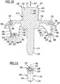
- the guide pin 214 engages in the interior of FIG Fig. 11 separately shown guide sleeve 116 and is thus displaceably guided on the guide sleeve 116 in the direction of a longitudinal central axis 220 of the guide sleeve 116, which is arranged coaxially to the longitudinal central axis 156 of the sealing element 128 in the operating state of the drain arrangement 100.
- the base plate 170, the guide pin 214 and the coupling projection 154 preferably form an integral base body 222 of the sealing element 128.
- the base body 222 of the sealing element 128 is preferably formed from a plastic material and can in particular be designed as an injection molded part.
- the sealing element 130 of the sealing element 128 is preferably formed from an elastomeric plastic material, in particular from a silicone material.
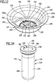
- the drain cup 104 of the drain fitting 102 is shown separately in FIGS 12 to 14 shown.
- the drain cup 104 is essentially funnel-shaped or bowl-shaped and comprises a bottom section 224, a side wall section 226 surrounding the bottom section 224 in an annular manner and an edge section 228 annularly surrounding the side wall section 226.
- the screen element 124 rests on the edge section 228 of the drain cup 104, preferably on an inner edge of the edge section 228 (with the screen bottom section 142 of the screen element 124) and / or on an outer edge of the edge section 228 (with the edge section 148 of the sieve element 124).
- the bottom portion 224 of the drain cup 104 has a central recess 230 in which a passage opening 232 for the passage of a shaft 234 of the guide element 115, for example in the form of the guide sleeve 116 (see Fig. 11 ), is provided.
- the guide sleeve 116 has a head 236, which has an outer diameter that exceeds the outer diameter of the shaft 234 and the outer diameter of the passage opening 232.
- the dimensions of the head 236 of the guide sleeve 116 and the recess 230 are coordinated with one another such that in the assembled state of the drain arrangement 100 the head 236 is completely accommodated in the recess 230 and not over the upper side 238 of the region of the base section 224 adjoining the recess 230 of the goblet 104 protrudes upwards (see in particular the 18 to 20 ).
- an upper side 240 of the head 236 of the guide sleeve 116 facing away from the shaft 234 is arranged substantially flush with the upper side 238 of the region of the bottom section 224 of the drainage cup 104 adjoining the depression 230.
- the multi-part drainage opening 122 is formed, which comprises a plurality of drainage holes 242 which follow one another in the circumferential direction of the drainage cup 104 in the exemplary embodiment shown in the drawings.
- the drain holes 242 are preferably arranged equidistantly from one another along the circumferential direction of the drain cup 104.
- One or more drain holes 242a have a larger passage area than a respectively adjacent drain hole 242b.
- the passage area of the adjacent drain hole 242b is reduced in particular by a support bar 246, which preferably extends on the radially outer edge of the drain hole 242b between the two webs 244 laterally delimiting the drain hole 242b.
- an upper side 248 of the support bar 246 lies lower than an upper side 250 of the web 244, which separates the drain hole 242b from the adjacent larger drain hole 242a.
- the support bar 246, which is lowered relative to the adjacent web 244, can be introduced into the bottom portion 224 of the drain cup 104 in particular by an embossing process.
- the top 248 of the support bar 246, a front edge 252 of the web 244 facing the support bar 246, the top 250 of the web 244 and a rear edge 254 of the web 244 facing away from the support bar 246 together form the above-mentioned run-side control contour 210, which with the Control contour 208 on the sealing element side cooperates with one of the control elements 186 of the sealing element 128 such that the height position of the sealing element 128 during the transfer of the sealing element 128 from the closed position into the open position and / or during the transfer of the sealing element 128 from the open position into the closed position in FIG is controlled in more detail below.
- the drain cup 104 may comprise a metallic material and / or a plastic material.
- the goblet 104 is formed essentially entirely from a metallic material or from a plastic material.
- the drain cup 104 can be inserted into an opening in the pool floor of the pool on which the drain arrangement 100 is arranged.
- the drain cup 104 is formed in one piece with the pelvic floor.
- valve upper part 106 comprises a bowl-shaped main body 256, which surrounds the drain cup 104 in the assembled state of the drain arrangement 100 (see Fig. 17 ) and sealingly rests on its upper edge via the seal 108 on the underside of the edge section 228 of the drain cup 104 and / or on the underside of the pelvic floor.
- the tubular overflow connection 110 opens into a side wall 258 of the main body 256, via which an overflow arrangement (not shown) of the basin on which the drain arrangement 100 is arranged, or a drain or an overflow of another basin, can be connected to the drain arrangement 100 such that Liquid from the relevant overflow or drain reaches the interior of the main body 256.
- the overflow connection 110 is preferably not arranged radially but, for example, tangentially on the main body 256. As a result, the overflow water is introduced eccentrically into the main body 256, which improves the drainage behavior and the overflow performance.
- the cross section of the tubular overflow connection 110 can in principle have any shape and, for example, be essentially circular, oval or angular.
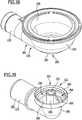
- the end of the overflow connection 110 facing away from the main body 256 is in the delivery state of the sequence arrangement 100 or in the operating state of the sequence arrangement 100, if no other overflow or sequence is to be connected to the sequence arrangement 100, by means of the in FIG 21 to 23 separately shown sealing plug 260 can be closed.
- the sealing plug 260 comprises a substantially hollow cylindrical section 262, the outer diameter of which corresponds essentially to the inner diameter of the overflow connection 110, so that the sealing plug 260 can be inserted in a sealing manner in the end region of the overflow connection 110.
- the fluid-tight seal between the sealing plug 260 and the overflow connection 110 can be provided by a seal (not shown) which is molded onto the inside of the overflow connection 110, for example injection molded, or is inserted or inserted into the overflow connection 110.
- sealing plug 260 could also be provided with a seal on its outside.
- Such a seal on the overflow connection 110 or on the sealing plug 260 can comprise, for example, an O-ring and / or a sealing sleeve and can be formed, for example, from a soft material or from a two-component material.
- the flange region 264 serves as a stop, which limits the insertion path of the sealing plug 260 in the longitudinal direction of the overflow connection 110.
- the end of the hollow cylindrical section 262 facing away from the flange region 264 is closed by an end wall 266.
- the sealing plug 260 further comprises a tool section 268, which, during assembly or disassembly of the drain arrangement, for connecting the guide sleeve 116 to the in Fig. 16 separately shown lower valve part 112 can be used.
- the tool section 268 has a polygonal, for example hexagonal, cross section, taken perpendicular to the longitudinal central axis 272 of the sealing plug 260, and that the actuating recess 270 of the guide sleeve 116 has a polygonal, complementary thereto, taken perpendicular to the longitudinal central axis 220 of the guide sleeve 116. for example hexagonal, cross-section.
- the tool section 268 is preferably connected via a support structure 274 to the hollow cylindrical section 262 and / or to the flange region 264 of the sealing plug 260 and is held essentially coaxially with the longitudinal central axis 272 of the sealing plug 260.
- the support structure 274 can comprise a plurality of, for example six, ribs 276, preferably running radially to the longitudinal central axis 272 of the sealing plug 260.
- the tool section 268 can also be provided with a recess 278, which preferably corresponds in terms of its shape to the outer contour of the tool section 268, but has smaller dimensions.
- the sealing plug 260 including the hollow cylindrical section 262, the flange area 264, the end wall 266, the support structure 274 and the tool section 268 is preferably formed as an integral part.
- the sealing plug 260 preferably comprises a plastic material.
- the sealing plug 260 is formed essentially entirely from a plastic material and is produced, for example, as an injection molded part.
- an upper valve part 106 with an overflow connection 110 an upper valve part without an overflow connection can also be used.
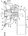
- valve upper part 106 has a through opening 280 on its underside, which is surrounded by an annular flange section 282 and, in the assembled state of the drain arrangement 100, engages with a flange section 284 of the valve bottom part 112 that is complementary thereto in such a way that the through opening 280 of the upper valve part 106 opens into an interior 286 of the lower valve part 112.
- liquid running out of the basin through the outlet opening 122 and / or liquid running out through the overflow connection 110 can reach the interior 286 of the lower valve part 112.
- a sealing ring 288 arranged between them serves to seal between the flange section 282 of the upper valve part 106 and the flange section 284 of the lower valve part 112.
- the draining liquid passes through the outlet bend 114 serving as a draining line 299 into a liquid discharge line (not shown) and finally into the sewage system.
- the lower valve part 112 further comprises an anchoring element 290, in which a lower end of the guide sleeve 116 can be anchored.
- the anchoring element 290 can be held on a side wall 298 of the lower valve part 112 via a support structure 296, and preferably in such a way that a longitudinal central axis of the anchoring element 290 is arranged coaxially with the longitudinal central axis 220 of the guide sleeve 116.
- the support structure 296 can in particular comprise a plurality of ribs 300, which are preferably radially oriented with respect to the longitudinal center axis of the anchoring element 290.
- the lower valve part 112 and / or the upper valve part 106 preferably comprise a plastic material.
- the lower valve part 112 and / or the upper valve part 106 is formed essentially entirely from a plastic material and is produced, for example, as an injection molded part.
- the procedure is as follows:
- the drain cup 104 is hung from above into an associated opening on the pool floor.
- the upper valve part 106 and the lower valve part 112 are joined together and applied with the seal 108 on the upper edge of the upper valve part 106 to the drainage cup 104 and the pelvic floor from below.
- the shaft 234 of the guide sleeve 116 is inserted through the passage opening 232 in the recess 230 of the bottom section 224 of the drain cup 104 into the anchoring element 290 of the valve lower part 112 and using the tool section 268 of the sealing plug 260, which engages with the actuating recess 270 of the guide sleeve 116 is brought, screwed into the internal thread of the anchoring element 290 by turning the sealing plug 260 until the drain cup 104, the valve lower part 112 and the intermediate valve upper part 106 are clamped together and the head 236 of the guide sleeve 116 is completely received in the recess 230 of the drain cup 104 (please refer Fig. 17 ).
- the sealing plug 260 can be arranged on the overflow connection 110 of the valve upper part 106 after the assembly of the guide sleeve 116.
- the upper valve part 106 thus serves as a receiving component 307, on which the mounting component 303 can be arranged when the assembly 120 is in the assembled state.
- the sealing element 128 is inserted into the drain cup 104 such that the guide pin 214 engages in the interior of the guide sleeve 116 and the control elements 186 each engage in one of the larger drain holes 242a.
- the sealing element 128 is in its in the 18 and 19 Shown closed position, in which the sealing element 130 rests with its sealing lip 182 sealingly against the bottom portion 224 of the drain cup 104 and thus prevents liquid from flowing out of the drain cup 104 through the drain opening 122.
- each control element 186 on the sealing element 128 along the circumferential direction of the sealing element 128 is preferably dimensioned such that in the in the 18 and 19 shown closed position of the sealing element 128, the front edge 198 of the control projection 188 bears against the rear edge 254 of the web 244 lying in front of the control projection 188 in question, viewed from above in the counterclockwise direction, and that the rear edge 196 of the stop projection 190 of the same control element 186 rests on the front Edge 252 of the web 244 lying behind the relevant control element 186, as seen from above in the counterclockwise direction.
- the sealing element 128 is centered with respect to the drain cup 104 such that the longitudinal central axis 156 of the sealing element 128 coincides with the longitudinal central axis 220 of the guide sleeve 116.
- the angular position of the sealing element 128 relative to the drain cup 104 is fixed in such a way that it is only counterclockwise by rotating the sealing element 128, as seen from above, while overcoming one Resistance that is required to lift the sealing member 128 is variable.
- the sieve element 124 is placed in a working position on the drain cup 104 in such a way that the coupling projection 154 of the sealing element 128 engages in the coupling receptacle 152 of the sieve element 124.
- the open position shown is carried out as follows: A user of the basin on which the drain assembly 100 is arranged grips the handle portion 136 of the sieve element 124 with his hand and rotates it (viewed from above) counterclockwise.
- the sealing element 128 is raised so much during the transition from the closed position to this intermediate position that the coupling projection 154 reaches the upper end of the coupling receptacle 152 and raises the sieve element 124, preferably a short distance, from the drain cup 104, which provides the user with haptic feedback that the intermediate position has been reached.
- the user of the basin on which the drain arrangement 100 is arranged can directly engage the coupling projection 154 of the sealing element 128 in order to move the sealing element 128 in the opening direction (in particular - viewed from above - counterclockwise) or in the closing direction (in particular - seen from above - clockwise) and thus move the sealing element 128 without the interposition of the sieve element 124 from the closed position to the open position or from the open position to the closed position.
- the sealing element 128 is raised so much during the transition from the closed position to this intermediate position that the coupling projection 154 reaches the upper end of the coupling receptacle 152 and raises the sieve element 124, preferably a short distance, from the drain cup 104, which provides the user with haptic feedback that the intermediate position has been reached.
- the second embodiment of the sequence arrangement 100 differs from the first embodiment in that the in the 29 and 30 Coupling element 134 of sieve element 124, which is shown separately, and which is connected in a rotationally fixed manner to base body 132 on the underside of grip section 136 of base body 132 of sieve element 124, unlike that in FIGS 6 and 7 Coupling element 134 shown in the first embodiment, is not essentially cup-shaped, with a closed ceiling wall facing the base body 132, but rather has a coupling receptacle 152 which penetrates the coupling element 134 from top to bottom and which, in the assembled state of the drain arrangement 100, also has a bottom Sealing element 128) and upwards (towards the base body 132 of the sieve element 124) is open.
- the second embodiment of the drain arrangement 100 differs from the first embodiment in an alternative embodiment of the sealing plug 260, by means of which the end of the overflow connection 110 facing away from the main body 256 of the valve upper part 106 in the delivery state of the drain arrangement 100 or in the operating state of the drain arrangement 100, if no other Overflow or drain to be connected to the drain assembly 100 is lockable.
- the sealing plug 260 comprises a substantially hollow cylindrical section 262, the outer diameter of which corresponds essentially to the inner diameter of the overflow connection 110, so that the sealing plug 260 can be inserted sealingly into the end region of the overflow connection 110, preferably with the interposition of a seal ,
- the flange region 264 serves as a stop, which limits the insertion path of the sealing plug 260 in the longitudinal direction of the overflow connection 110.
- One or more, for example two, extensions 306 can be arranged on the outer circumference of the flange region 246, which extensions are, for example, parallel to the longitudinal central axis 272 of the sealing plug 260 and preferably in the direction of the end of the hollow cylindrical section 262 facing the valve lower part 112 when the sealing plug 260 is in the inserted state to extend.
- the extensions 306 can serve as injection points if the sealing plug 260 is produced as an injection molded part.
- the at least one extension 306 can serve to indicate the angular position of the closure plug 260 when the closure plug 260 rotates about its longitudinal central axis 272, in particular when the closure plug 260 is used to screw the shaft 234 of the guide sleeve 116 into the internal thread of the anchoring element 290 (see Fig. 40 ) is used.
- the end of the hollow cylindrical section 262 facing away from the flange region 264 is closed by an end wall 266.
- the sealing plug 260 further comprises a tool section 268, which, during assembly or disassembly of the drain arrangement, for connecting the guide sleeve 116 to the in Fig. 39 separately shown lower valve part 112 can be used.
- This tool section 268 protrudes from the outside of the end wall 266 along the longitudinal central axis 272 of the sealing plug 260 (see FIGS 46 and 47 ).
- the tool section 268 has an outer contour which is complementary to the actuating recess 270 on the head 236 of the guide sleeve 116, so that the tool section 268 is brought into engagement with the actuating recess 270 and then the guide sleeve 116 by rotating the closure plug 260 about its longitudinal central axis 272 can be rotated about the longitudinal central axis 220 of the guide sleeve 116.
- the tool section 269 has a polygonal, for example hexagonal, cross section, taken perpendicular to the longitudinal central axis 272 of the sealing plug 260, and that the actuating recess 270 of the guide sleeve 116 has a polygonal, complementary thereto, taken perpendicular to the longitudinal central axis 220 of the guide sleeve 116. for example hexagonal, cross-section.
- the sealing plug 260 is stiffened by a support structure 274, which comprises a plurality of, for example six, ribs 276 running radially from the inside of the hollow cylindrical section 262 of the sealing plug 260 in the direction of the longitudinal central axis 272 of the sealing plug 260, which ribs at one center Central body 308 arranged in the interior of the closure plug 260, which is preferably essentially cylindrical and preferably projects from the inside of the end wall 266 into the interior of the closure plug 260.
- the central body can be provided with an actuating recess 310, preferably arranged in the center.
- the actuating recess 310 can have a polygonal, for example hexagonal, cross section and can be brought into engagement with a component that is complementary and also has a polygonal, for example hexagonal, cross section (not shown), by rotating the closure plug 260 about its longitudinal central axis 272 to rotate a longitudinal central axis of the component in question.
Landscapes
- Engineering & Computer Science (AREA)
- Environmental & Geological Engineering (AREA)
- Health & Medical Sciences (AREA)
- Life Sciences & Earth Sciences (AREA)
- Hydrology & Water Resources (AREA)
- Public Health (AREA)
- Water Supply & Treatment (AREA)
- Mechanical Engineering (AREA)
- Sink And Installation For Waste Water (AREA)
Claims (15)
- Ensemble pour la fermeture d'une ouverture d'évacuation (122) d'un bac, en particulier d'un bac d'un évier, disposée sur une coupe d'évacuation (104), l'ensemble comprenant
un élément d'étanchéité (128), qui, dans une position de fermeture, s'applique de manière étanche contre la coupe d'évacuation (104) et, dans une position d'ouverture, permet une évacuation d'un liquide du bac à travers l'ouverture d'évacuation (122), dans lequel l'élément d'étanchéité (128) comprend une tige de guidage (214),
un élément de guidage (115), sur lequel la tige de guidage (214) de l'élément d'étanchéité (128) est guidée mobile dans la direction verticale dans l'état monté de l'ensemble (120), et
une pièce d'ancrage (305), sur laquelle l'élément de guidage (115) est monté dans l'état monté de l'ensemble (120),
caractérisé
en ce que l'ensemble (120) comprend une pièce de montage (303), qui peut être utilisée pour le montage de l'élément de guidage (115) sur la pièce d'ancrage (305) pendant le montage de l'ensemble (120), et
une pièce de logement (307), sur laquelle la pièce de montage (303) peut être disposée dans l'état monté de l'ensemble (120). - Ensemble selon la revendication 1, caractérisé en ce que la pièce de montage (303) peut être utilisée pour produire un mouvement rotatif de l'élément de guidage (115) autour d'un axe longitudinal médian (220) de l'élément de guidage (115).
- Ensemble selon l'une quelconque des revendications 1 ou 2, caractérisé en ce que la pièce de montage (303) comprend une partie outil (268) et l'élément de guidage (115) comprend une partie d'actionnement (269),
dans lequel la partie outil (268) et la partie d'actionnement (269) peuvent être amenées en contact l'une avec l'autre, de sorte que la partie d'actionnement (269) peut être amenée en rotation au moyen de la partie outil (268). - Ensemble selon la revendication 3, caractérisé en ce que la partie outil (268) présente un contour extérieur, qui est réalisé de manière complémentaire à un contour intérieur de la partie d'actionnement (269), et/ou un contour intérieur, qui est réalisé de manière complémentaire à un contour extérieur de la partie d'actionnement (269),
dans lequel, de préférence, le contour extérieur de la partie outil (268) et le contour intérieur de la partie d'actionnement (269) et/ou le contour intérieur de la partie outil (268) et le contour extérieur de la partie d'actionnement (269) sont réalisés de manière polygonale. - Ensemble selon l'une quelconque des revendications 1 à 4, caractérisé en ce que l'élément de guidage (115) présente un filet, lequel, dans l'état monté de l'ensemble (120), est en contact avec un filet complémentaire à celui-ci de la pièce d'ancrage (305).
- Ensemble selon l'une quelconque des revendications 1 à 5, caractérisé en ce que l'élément de guidage (115) est réalisé sous la forme d'une vis creuse (118).
- Ensemble selon l'une quelconque des revendications 1 à 6, caractérisé en ce que la pièce d'ancrage (305) est réalisée sous la forme d'une partie valve de l'ensemble (120).
- Ensemble selon l'une quelconque des revendications 1 à 7, caractérisé en ce qu'une conduite d'évacuation (299), à travers laquelle le liquide peut s'évacuer de l'ensemble (120), est prévue sur la pièce d'ancrage (305).
- Ensemble selon l'une quelconque des revendications 1 à 8, caractérisé en ce que la coupe d'évacuation (104) présente un évidement (230), dans lequel, dans l'état monté de l'ensemble (120), une partie supérieure de l'élément de guidage (115) est logée au moins en partie.
- Ensemble selon la revendication 9, caractérisé en ce que, dans l'état monté de l'ensemble (120), l'élément de guidage (115) ne fait pas saillie vers le haut d'une face supérieure (238) d'une zone, de la coupe d'évacuation (104), adjacente à l'évidement (230),
dans lequel, de préférence, dans l'état monté de l'ensemble (120), une face supérieure (240) de l'élément de guidage (115) est disposée sensiblement à fleur avec la surface supérieure (238) de la zone, de la coupe d'évacuation (104), adjacente à l'évidement (230) . - Ensemble selon l'une quelconque des revendications 1 à 10, caractérisé en ce que la pièce de montage (303) est réalisée sous la forme d'un bouchon de fermeture (260).
- Ensemble selon l'une quelconque des revendications 1 à 11, caractérisé en ce que la pièce de logement (307) est réalisée sous la forme d'une partie valve de l'ensemble (120).
- Ensemble selon l'une quelconque des revendications 1 à 12, caractérisé en ce qu'un raccord de trop-plein (110), auquel un trop-plein du bac ou un trop-plein ou une évacuation d'un autre bac peut être raccordé(e) à l'ensemble (120), est prévu sur la pièce de logement (307).
- Ensemble selon l'une quelconque des revendications 1 à 13, caractérisé en ce que la pièce de montage (303) est réalisée sous la forme d'une pièce moulée par injection.
- Procédé de montage d'un ensemble (120) pour la fermeture d'une ouverture d'évacuation (122) d'un bac, en particulier d'un bac d'un évier, comprenant les éléments suivants :- le montage d'un élément de guidage (115) sur une pièce d'ancrage (305) de l'ensemble (120) au moyen d'une pièce de montage (303) de l'ensemble (120) ;- la disposition de la pièce de montage (303) sur une pièce de logement (307) de l'ensemble (120) ;- la disposition d'une tige de guidage (214) d'un élément d'étanchéité (128) de l'ensemble (120) sur l'élément de guidage (115), de telle sorte que la tige de guidage (214) est guidée mobile sur l'élément de guidage (115) dans la direction verticale.
Applications Claiming Priority (1)
| Application Number | Priority Date | Filing Date | Title |
|---|---|---|---|
| DE102015120364.2A DE102015120364A1 (de) | 2015-11-25 | 2015-11-25 | Baugruppe zum Verschließen einer Ablauföffnung eines Beckens und Verfahren zum Montieren einer solchen Baugruppe |
Publications (2)
| Publication Number | Publication Date |
|---|---|
| EP3173540A1 EP3173540A1 (fr) | 2017-05-31 |
| EP3173540B1 true EP3173540B1 (fr) | 2020-01-01 |
Family
ID=57288225
Family Applications (1)
| Application Number | Title | Priority Date | Filing Date |
|---|---|---|---|
| EP16198366.3A Active EP3173540B1 (fr) | 2015-11-25 | 2016-11-11 | Module de fermeture de trou de vidange d'une cuve et procédé de montage d'un tel module |
Country Status (2)
| Country | Link |
|---|---|
| EP (1) | EP3173540B1 (fr) |
| DE (1) | DE102015120364A1 (fr) |
Families Citing this family (1)
| Publication number | Priority date | Publication date | Assignee | Title |
|---|---|---|---|---|
| IT202300025893A1 (it) * | 2023-12-05 | 2025-06-05 | C G S S R L | Piletta universale per dispositivi igienico-sanitari. |
Family Cites Families (4)
| Publication number | Priority date | Publication date | Assignee | Title |
|---|---|---|---|---|
| US5832544A (en) * | 1997-12-29 | 1998-11-10 | Pan; Chin-Chi | Sink drain stopper |
| DE29814835U1 (de) * | 1998-08-19 | 2000-02-24 | Stadur Produktions-Verwaltungs GmbH, 21684 Stade | Ablauf zum Einbau in flächige Trägerelemente |
| DE20000729U1 (de) * | 2000-01-18 | 2000-03-16 | Niro-Plan Ag, Zug | Ablaufstöpsel für Ablaufarmaturen |
| TWM403519U (en) * | 2010-09-10 | 2011-05-11 | Ming-Tu Zheng | Improved drainage grating structure |
-
2015
- 2015-11-25 DE DE102015120364.2A patent/DE102015120364A1/de not_active Withdrawn
-
2016
- 2016-11-11 EP EP16198366.3A patent/EP3173540B1/fr active Active
Non-Patent Citations (1)
| Title |
|---|
| None * |
Also Published As
| Publication number | Publication date |
|---|---|
| DE102015120364A1 (de) | 2017-06-01 |
| EP3173540A1 (fr) | 2017-05-31 |
Similar Documents
| Publication | Publication Date | Title |
|---|---|---|
| DE69000863T2 (de) | Becherfoermiges sieb fuer ablaufventil mit fernbetaetigung. | |
| EP1206176B1 (fr) | Dispositif pour distribuer des aliments a des animaux | |
| DE69222783T2 (de) | Ausgabe-Verschluss mit Drehring | |
| EP1674629A2 (fr) | Dispositif d'écoulement pour montage à une plaque de plancher avec une ouverture pour eau d'écoulement et ensemble d'un tel dispositif d'écoulement à une plaque de plancher | |
| DE10310563B4 (de) | Korken für einen Behälter | |
| EP3173541B1 (fr) | Module de fermeture d'un trou d'évacuation d'une cuve | |
| EP3173540B1 (fr) | Module de fermeture de trou de vidange d'une cuve et procédé de montage d'un tel module | |
| DE20118252U1 (de) | Einsatzelement für Abflüsse von Wannen, Spülen o.dgl. | |
| EP3455421B1 (fr) | Vanne de vidange pour réservoir de chasse-d'eau et réservoir de chasse-d'eau muni d'une vanne de vidange | |
| DE102004054642B4 (de) | Sanitärarmatur, insbesondere sanitäre Unterputzarmatur | |
| DE102006018612A1 (de) | Stopfen | |
| DE102012215764A1 (de) | Siebelement für einen Ablauf eines Beckens | |
| DE202017100472U1 (de) | Ablaufgarnitur mit heb- und senkbarem Ablaufstopfen | |
| EP2853643B1 (fr) | Système de corps de raccordement pour une robinetterie encastrée | |
| EP3272954B1 (fr) | Système d'évacuation | |
| DE102004035652B4 (de) | Verschlussvorrichtung für ein Sanitärbecken sowie Verwendung eines Drucktasters zur Betätigung eines Verschlussstopfens | |
| CH706562B1 (de) | Siphon mit integrierter Reinigungsfunktion. | |
| EP2481856A1 (fr) | Unité de soupape de remplissage | |
| EP3647504B1 (fr) | Dispositif formant article sanitaire | |
| DE3737162A1 (de) | Armatur mit schraubenlosem deckel | |
| EP4323594B1 (fr) | Adaptateur pour dispositif de drainage | |
| EP3735496A1 (fr) | Dispositif de fermeture | |
| CH705794A2 (de) | Bodenablauf, insbesondere im Boden einer Wanne oder eines Beckens. | |
| WO2006053645A1 (fr) | Evier | |
| DE3911499A1 (de) | Ablaufarmatur fuer spueltische oder dergleichen |
Legal Events
| Date | Code | Title | Description |
|---|---|---|---|
| PUAI | Public reference made under article 153(3) epc to a published international application that has entered the european phase |
Free format text: ORIGINAL CODE: 0009012 |
|
| STAA | Information on the status of an ep patent application or granted ep patent |
Free format text: STATUS: THE APPLICATION HAS BEEN PUBLISHED |
|
| AK | Designated contracting states |
Kind code of ref document: A1 Designated state(s): AL AT BE BG CH CY CZ DE DK EE ES FI FR GB GR HR HU IE IS IT LI LT LU LV MC MK MT NL NO PL PT RO RS SE SI SK SM TR |
|
| AX | Request for extension of the european patent |
Extension state: BA ME |
|
| STAA | Information on the status of an ep patent application or granted ep patent |
Free format text: STATUS: REQUEST FOR EXAMINATION WAS MADE |
|
| 17P | Request for examination filed |
Effective date: 20171130 |
|
| RBV | Designated contracting states (corrected) |
Designated state(s): AL AT BE BG CH CY CZ DE DK EE ES FI FR GB GR HR HU IE IS IT LI LT LU LV MC MK MT NL NO PL PT RO RS SE SI SK SM TR |
|
| GRAP | Despatch of communication of intention to grant a patent |
Free format text: ORIGINAL CODE: EPIDOSNIGR1 |
|
| STAA | Information on the status of an ep patent application or granted ep patent |
Free format text: STATUS: GRANT OF PATENT IS INTENDED |
|
| INTG | Intention to grant announced |
Effective date: 20190614 |
|
| GRAS | Grant fee paid |
Free format text: ORIGINAL CODE: EPIDOSNIGR3 |
|
| GRAA | (expected) grant |
Free format text: ORIGINAL CODE: 0009210 |
|
| STAA | Information on the status of an ep patent application or granted ep patent |
Free format text: STATUS: THE PATENT HAS BEEN GRANTED |
|
| AK | Designated contracting states |
Kind code of ref document: B1 Designated state(s): AL AT BE BG CH CY CZ DE DK EE ES FI FR GB GR HR HU IE IS IT LI LT LU LV MC MK MT NL NO PL PT RO RS SE SI SK SM TR |
|
| REG | Reference to a national code |
Ref country code: GB Ref legal event code: FG4D Free format text: NOT ENGLISH |
|
| REG | Reference to a national code |
Ref country code: CH Ref legal event code: EP Ref country code: CH Ref legal event code: NV Representative=s name: ISLER AND PEDRAZZINI AG, CH Ref country code: AT Ref legal event code: REF Ref document number: 1219923 Country of ref document: AT Kind code of ref document: T Effective date: 20200115 |
|
| REG | Reference to a national code |
Ref country code: DE Ref legal event code: R096 Ref document number: 502016008224 Country of ref document: DE |
|
| REG | Reference to a national code |
Ref country code: IE Ref legal event code: FG4D Free format text: LANGUAGE OF EP DOCUMENT: GERMAN |
|
| REG | Reference to a national code |
Ref country code: NL Ref legal event code: MP Effective date: 20200101 |
|
| REG | Reference to a national code |
Ref country code: LT Ref legal event code: MG4D |
|
| PG25 | Lapsed in a contracting state [announced via postgrant information from national office to epo] |
Ref country code: NO Free format text: LAPSE BECAUSE OF FAILURE TO SUBMIT A TRANSLATION OF THE DESCRIPTION OR TO PAY THE FEE WITHIN THE PRESCRIBED TIME-LIMIT Effective date: 20200401 Ref country code: FI Free format text: LAPSE BECAUSE OF FAILURE TO SUBMIT A TRANSLATION OF THE DESCRIPTION OR TO PAY THE FEE WITHIN THE PRESCRIBED TIME-LIMIT Effective date: 20200101 Ref country code: PT Free format text: LAPSE BECAUSE OF FAILURE TO SUBMIT A TRANSLATION OF THE DESCRIPTION OR TO PAY THE FEE WITHIN THE PRESCRIBED TIME-LIMIT Effective date: 20200527 Ref country code: CZ Free format text: LAPSE BECAUSE OF FAILURE TO SUBMIT A TRANSLATION OF THE DESCRIPTION OR TO PAY THE FEE WITHIN THE PRESCRIBED TIME-LIMIT Effective date: 20200101 Ref country code: RS Free format text: LAPSE BECAUSE OF FAILURE TO SUBMIT A TRANSLATION OF THE DESCRIPTION OR TO PAY THE FEE WITHIN THE PRESCRIBED TIME-LIMIT Effective date: 20200101 Ref country code: NL Free format text: LAPSE BECAUSE OF FAILURE TO SUBMIT A TRANSLATION OF THE DESCRIPTION OR TO PAY THE FEE WITHIN THE PRESCRIBED TIME-LIMIT Effective date: 20200101 Ref country code: LT Free format text: LAPSE BECAUSE OF FAILURE TO SUBMIT A TRANSLATION OF THE DESCRIPTION OR TO PAY THE FEE WITHIN THE PRESCRIBED TIME-LIMIT Effective date: 20200101 |
|
| PG25 | Lapsed in a contracting state [announced via postgrant information from national office to epo] |
Ref country code: GR Free format text: LAPSE BECAUSE OF FAILURE TO SUBMIT A TRANSLATION OF THE DESCRIPTION OR TO PAY THE FEE WITHIN THE PRESCRIBED TIME-LIMIT Effective date: 20200402 Ref country code: BG Free format text: LAPSE BECAUSE OF FAILURE TO SUBMIT A TRANSLATION OF THE DESCRIPTION OR TO PAY THE FEE WITHIN THE PRESCRIBED TIME-LIMIT Effective date: 20200401 Ref country code: IS Free format text: LAPSE BECAUSE OF FAILURE TO SUBMIT A TRANSLATION OF THE DESCRIPTION OR TO PAY THE FEE WITHIN THE PRESCRIBED TIME-LIMIT Effective date: 20200501 Ref country code: SE Free format text: LAPSE BECAUSE OF FAILURE TO SUBMIT A TRANSLATION OF THE DESCRIPTION OR TO PAY THE FEE WITHIN THE PRESCRIBED TIME-LIMIT Effective date: 20200101 Ref country code: LV Free format text: LAPSE BECAUSE OF FAILURE TO SUBMIT A TRANSLATION OF THE DESCRIPTION OR TO PAY THE FEE WITHIN THE PRESCRIBED TIME-LIMIT Effective date: 20200101 Ref country code: HR Free format text: LAPSE BECAUSE OF FAILURE TO SUBMIT A TRANSLATION OF THE DESCRIPTION OR TO PAY THE FEE WITHIN THE PRESCRIBED TIME-LIMIT Effective date: 20200101 |
|
| REG | Reference to a national code |
Ref country code: DE Ref legal event code: R097 Ref document number: 502016008224 Country of ref document: DE |
|
| PG25 | Lapsed in a contracting state [announced via postgrant information from national office to epo] |
Ref country code: DK Free format text: LAPSE BECAUSE OF FAILURE TO SUBMIT A TRANSLATION OF THE DESCRIPTION OR TO PAY THE FEE WITHIN THE PRESCRIBED TIME-LIMIT Effective date: 20200101 Ref country code: SK Free format text: LAPSE BECAUSE OF FAILURE TO SUBMIT A TRANSLATION OF THE DESCRIPTION OR TO PAY THE FEE WITHIN THE PRESCRIBED TIME-LIMIT Effective date: 20200101 Ref country code: SM Free format text: LAPSE BECAUSE OF FAILURE TO SUBMIT A TRANSLATION OF THE DESCRIPTION OR TO PAY THE FEE WITHIN THE PRESCRIBED TIME-LIMIT Effective date: 20200101 Ref country code: EE Free format text: LAPSE BECAUSE OF FAILURE TO SUBMIT A TRANSLATION OF THE DESCRIPTION OR TO PAY THE FEE WITHIN THE PRESCRIBED TIME-LIMIT Effective date: 20200101 Ref country code: RO Free format text: LAPSE BECAUSE OF FAILURE TO SUBMIT A TRANSLATION OF THE DESCRIPTION OR TO PAY THE FEE WITHIN THE PRESCRIBED TIME-LIMIT Effective date: 20200101 Ref country code: ES Free format text: LAPSE BECAUSE OF FAILURE TO SUBMIT A TRANSLATION OF THE DESCRIPTION OR TO PAY THE FEE WITHIN THE PRESCRIBED TIME-LIMIT Effective date: 20200101 |
|
| PLBE | No opposition filed within time limit |
Free format text: ORIGINAL CODE: 0009261 |
|
| STAA | Information on the status of an ep patent application or granted ep patent |
Free format text: STATUS: NO OPPOSITION FILED WITHIN TIME LIMIT |
|
| 26N | No opposition filed |
Effective date: 20201002 |
|
| PG25 | Lapsed in a contracting state [announced via postgrant information from national office to epo] |
Ref country code: IT Free format text: LAPSE BECAUSE OF FAILURE TO SUBMIT A TRANSLATION OF THE DESCRIPTION OR TO PAY THE FEE WITHIN THE PRESCRIBED TIME-LIMIT Effective date: 20200101 |
|
| PG25 | Lapsed in a contracting state [announced via postgrant information from national office to epo] |
Ref country code: PL Free format text: LAPSE BECAUSE OF FAILURE TO SUBMIT A TRANSLATION OF THE DESCRIPTION OR TO PAY THE FEE WITHIN THE PRESCRIBED TIME-LIMIT Effective date: 20200101 Ref country code: SI Free format text: LAPSE BECAUSE OF FAILURE TO SUBMIT A TRANSLATION OF THE DESCRIPTION OR TO PAY THE FEE WITHIN THE PRESCRIBED TIME-LIMIT Effective date: 20200101 |
|
| PG25 | Lapsed in a contracting state [announced via postgrant information from national office to epo] |
Ref country code: MC Free format text: LAPSE BECAUSE OF FAILURE TO SUBMIT A TRANSLATION OF THE DESCRIPTION OR TO PAY THE FEE WITHIN THE PRESCRIBED TIME-LIMIT Effective date: 20200101 |
|
| REG | Reference to a national code |
Ref country code: CH Ref legal event code: PL |
|
| PG25 | Lapsed in a contracting state [announced via postgrant information from national office to epo] |
Ref country code: LU Free format text: LAPSE BECAUSE OF NON-PAYMENT OF DUE FEES Effective date: 20201111 |
|
| REG | Reference to a national code |
Ref country code: BE Ref legal event code: MM Effective date: 20201130 |
|
| PG25 | Lapsed in a contracting state [announced via postgrant information from national office to epo] |
Ref country code: CH Free format text: LAPSE BECAUSE OF NON-PAYMENT OF DUE FEES Effective date: 20201130 Ref country code: LI Free format text: LAPSE BECAUSE OF NON-PAYMENT OF DUE FEES Effective date: 20201130 |
|
| PG25 | Lapsed in a contracting state [announced via postgrant information from national office to epo] |
Ref country code: IE Free format text: LAPSE BECAUSE OF NON-PAYMENT OF DUE FEES Effective date: 20201111 |
|
| PG25 | Lapsed in a contracting state [announced via postgrant information from national office to epo] |
Ref country code: TR Free format text: LAPSE BECAUSE OF FAILURE TO SUBMIT A TRANSLATION OF THE DESCRIPTION OR TO PAY THE FEE WITHIN THE PRESCRIBED TIME-LIMIT Effective date: 20200101 Ref country code: MT Free format text: LAPSE BECAUSE OF FAILURE TO SUBMIT A TRANSLATION OF THE DESCRIPTION OR TO PAY THE FEE WITHIN THE PRESCRIBED TIME-LIMIT Effective date: 20200101 Ref country code: CY Free format text: LAPSE BECAUSE OF FAILURE TO SUBMIT A TRANSLATION OF THE DESCRIPTION OR TO PAY THE FEE WITHIN THE PRESCRIBED TIME-LIMIT Effective date: 20200101 |
|
| PG25 | Lapsed in a contracting state [announced via postgrant information from national office to epo] |
Ref country code: MK Free format text: LAPSE BECAUSE OF FAILURE TO SUBMIT A TRANSLATION OF THE DESCRIPTION OR TO PAY THE FEE WITHIN THE PRESCRIBED TIME-LIMIT Effective date: 20200101 Ref country code: AL Free format text: LAPSE BECAUSE OF FAILURE TO SUBMIT A TRANSLATION OF THE DESCRIPTION OR TO PAY THE FEE WITHIN THE PRESCRIBED TIME-LIMIT Effective date: 20200101 |
|
| PG25 | Lapsed in a contracting state [announced via postgrant information from national office to epo] |
Ref country code: BE Free format text: LAPSE BECAUSE OF NON-PAYMENT OF DUE FEES Effective date: 20201130 |
|
| REG | Reference to a national code |
Ref country code: AT Ref legal event code: MM01 Ref document number: 1219923 Country of ref document: AT Kind code of ref document: T Effective date: 20211111 |
|
| PG25 | Lapsed in a contracting state [announced via postgrant information from national office to epo] |
Ref country code: AT Free format text: LAPSE BECAUSE OF NON-PAYMENT OF DUE FEES Effective date: 20211111 |
|
| PGFP | Annual fee paid to national office [announced via postgrant information from national office to epo] |
Ref country code: DE Payment date: 20251118 Year of fee payment: 10 |
|
| PGFP | Annual fee paid to national office [announced via postgrant information from national office to epo] |
Ref country code: GB Payment date: 20251120 Year of fee payment: 10 |
|
| PGFP | Annual fee paid to national office [announced via postgrant information from national office to epo] |
Ref country code: FR Payment date: 20251120 Year of fee payment: 10 |