EP3173787A1 - Système de réseau de culture de cellules pour épreuves automatisées et procédés de fonctionnement et de fabrication de celui-ci - Google Patents
Système de réseau de culture de cellules pour épreuves automatisées et procédés de fonctionnement et de fabrication de celui-ci Download PDFInfo
- Publication number
- EP3173787A1 EP3173787A1 EP16185733.9A EP16185733A EP3173787A1 EP 3173787 A1 EP3173787 A1 EP 3173787A1 EP 16185733 A EP16185733 A EP 16185733A EP 3173787 A1 EP3173787 A1 EP 3173787A1
- Authority
- EP
- European Patent Office
- Prior art keywords
- cell culture
- cell
- microfluidic
- inlet
- channels
- Prior art date
- Legal status (The legal status is an assumption and is not a legal conclusion. Google has not performed a legal analysis and makes no representation as to the accuracy of the status listed.)
- Granted
Links
Images


Classifications
-
- C—CHEMISTRY; METALLURGY
- C12—BIOCHEMISTRY; BEER; SPIRITS; WINE; VINEGAR; MICROBIOLOGY; ENZYMOLOGY; MUTATION OR GENETIC ENGINEERING
- C12M—APPARATUS FOR ENZYMOLOGY OR MICROBIOLOGY; APPARATUS FOR CULTURING MICROORGANISMS FOR PRODUCING BIOMASS, FOR GROWING CELLS OR FOR OBTAINING FERMENTATION OR METABOLIC PRODUCTS, i.e. BIOREACTORS OR FERMENTERS
- C12M23/00—Constructional details, e.g. recesses, hinges
- C12M23/02—Form or structure of the vessel
- C12M23/16—Microfluidic devices; Capillary tubes
-
- B—PERFORMING OPERATIONS; TRANSPORTING
- B01—PHYSICAL OR CHEMICAL PROCESSES OR APPARATUS IN GENERAL
- B01L—CHEMICAL OR PHYSICAL LABORATORY APPARATUS FOR GENERAL USE
- B01L3/00—Containers or dishes for laboratory use, e.g. laboratory glassware; Droppers
- B01L3/50—Containers for the purpose of retaining a material to be analysed, e.g. test tubes
- B01L3/502—Containers for the purpose of retaining a material to be analysed, e.g. test tubes with fluid transport, e.g. in multi-compartment structures
- B01L3/5027—Containers for the purpose of retaining a material to be analysed, e.g. test tubes with fluid transport, e.g. in multi-compartment structures by integrated microfluidic structures, i.e. dimensions of channels and chambers are such that surface tension forces are important, e.g. lab-on-a-chip
- B01L3/502715—Containers for the purpose of retaining a material to be analysed, e.g. test tubes with fluid transport, e.g. in multi-compartment structures by integrated microfluidic structures, i.e. dimensions of channels and chambers are such that surface tension forces are important, e.g. lab-on-a-chip characterised by interfacing components, e.g. fluidic, electrical, optical or mechanical interfaces
-
- B—PERFORMING OPERATIONS; TRANSPORTING
- B01—PHYSICAL OR CHEMICAL PROCESSES OR APPARATUS IN GENERAL
- B01L—CHEMICAL OR PHYSICAL LABORATORY APPARATUS FOR GENERAL USE
- B01L3/00—Containers or dishes for laboratory use, e.g. laboratory glassware; Droppers
- B01L3/50—Containers for the purpose of retaining a material to be analysed, e.g. test tubes
- B01L3/502—Containers for the purpose of retaining a material to be analysed, e.g. test tubes with fluid transport, e.g. in multi-compartment structures
- B01L3/5027—Containers for the purpose of retaining a material to be analysed, e.g. test tubes with fluid transport, e.g. in multi-compartment structures by integrated microfluidic structures, i.e. dimensions of channels and chambers are such that surface tension forces are important, e.g. lab-on-a-chip
- B01L3/50273—Containers for the purpose of retaining a material to be analysed, e.g. test tubes with fluid transport, e.g. in multi-compartment structures by integrated microfluidic structures, i.e. dimensions of channels and chambers are such that surface tension forces are important, e.g. lab-on-a-chip characterised by the means or forces applied to move the fluids
-
- B—PERFORMING OPERATIONS; TRANSPORTING
- B01—PHYSICAL OR CHEMICAL PROCESSES OR APPARATUS IN GENERAL
- B01L—CHEMICAL OR PHYSICAL LABORATORY APPARATUS FOR GENERAL USE
- B01L3/00—Containers or dishes for laboratory use, e.g. laboratory glassware; Droppers
- B01L3/50—Containers for the purpose of retaining a material to be analysed, e.g. test tubes
- B01L3/502—Containers for the purpose of retaining a material to be analysed, e.g. test tubes with fluid transport, e.g. in multi-compartment structures
- B01L3/5027—Containers for the purpose of retaining a material to be analysed, e.g. test tubes with fluid transport, e.g. in multi-compartment structures by integrated microfluidic structures, i.e. dimensions of channels and chambers are such that surface tension forces are important, e.g. lab-on-a-chip
- B01L3/502761—Containers for the purpose of retaining a material to be analysed, e.g. test tubes with fluid transport, e.g. in multi-compartment structures by integrated microfluidic structures, i.e. dimensions of channels and chambers are such that surface tension forces are important, e.g. lab-on-a-chip specially adapted for handling suspended solids or molecules independently from the bulk fluid flow, e.g. for trapping or sorting beads or physically stretching molecules
-
- C—CHEMISTRY; METALLURGY
- C12—BIOCHEMISTRY; BEER; SPIRITS; WINE; VINEGAR; MICROBIOLOGY; ENZYMOLOGY; MUTATION OR GENETIC ENGINEERING
- C12M—APPARATUS FOR ENZYMOLOGY OR MICROBIOLOGY; APPARATUS FOR CULTURING MICROORGANISMS FOR PRODUCING BIOMASS, FOR GROWING CELLS OR FOR OBTAINING FERMENTATION OR METABOLIC PRODUCTS, i.e. BIOREACTORS OR FERMENTERS
- C12M23/00—Constructional details, e.g. recesses, hinges
- C12M23/02—Form or structure of the vessel
- C12M23/12—Well or multiwell plates
-
- C—CHEMISTRY; METALLURGY
- C12—BIOCHEMISTRY; BEER; SPIRITS; WINE; VINEGAR; MICROBIOLOGY; ENZYMOLOGY; MUTATION OR GENETIC ENGINEERING
- C12M—APPARATUS FOR ENZYMOLOGY OR MICROBIOLOGY; APPARATUS FOR CULTURING MICROORGANISMS FOR PRODUCING BIOMASS, FOR GROWING CELLS OR FOR OBTAINING FERMENTATION OR METABOLIC PRODUCTS, i.e. BIOREACTORS OR FERMENTERS
- C12M29/00—Means for introduction, extraction or recirculation of materials, e.g. pumps
- C12M29/10—Perfusion
-
- C—CHEMISTRY; METALLURGY
- C12—BIOCHEMISTRY; BEER; SPIRITS; WINE; VINEGAR; MICROBIOLOGY; ENZYMOLOGY; MUTATION OR GENETIC ENGINEERING
- C12M—APPARATUS FOR ENZYMOLOGY OR MICROBIOLOGY; APPARATUS FOR CULTURING MICROORGANISMS FOR PRODUCING BIOMASS, FOR GROWING CELLS OR FOR OBTAINING FERMENTATION OR METABOLIC PRODUCTS, i.e. BIOREACTORS OR FERMENTERS
- C12M41/00—Means for regulation, monitoring, measurement or control, e.g. flow regulation
- C12M41/48—Automatic or computerized control
-
- G—PHYSICS
- G01—MEASURING; TESTING
- G01N—INVESTIGATING OR ANALYSING MATERIALS BY DETERMINING THEIR CHEMICAL OR PHYSICAL PROPERTIES
- G01N35/00—Automatic analysis not limited to methods or materials provided for in any single one of groups G01N1/00 - G01N33/00; Handling materials therefor
- G01N35/00029—Automatic analysis not limited to methods or materials provided for in any single one of groups G01N1/00 - G01N33/00; Handling materials therefor provided with flat sample substrates, e.g. slides
-
- G—PHYSICS
- G01—MEASURING; TESTING
- G01N—INVESTIGATING OR ANALYSING MATERIALS BY DETERMINING THEIR CHEMICAL OR PHYSICAL PROPERTIES
- G01N35/00—Automatic analysis not limited to methods or materials provided for in any single one of groups G01N1/00 - G01N33/00; Handling materials therefor
- G01N35/0099—Automatic analysis not limited to methods or materials provided for in any single one of groups G01N1/00 - G01N33/00; Handling materials therefor comprising robots or similar manipulators
-
- B—PERFORMING OPERATIONS; TRANSPORTING
- B01—PHYSICAL OR CHEMICAL PROCESSES OR APPARATUS IN GENERAL
- B01L—CHEMICAL OR PHYSICAL LABORATORY APPARATUS FOR GENERAL USE
- B01L2300/00—Additional constructional details
- B01L2300/08—Geometry, shape and general structure
- B01L2300/0809—Geometry, shape and general structure rectangular shaped
- B01L2300/0829—Multi-well plates; Microtitration plates
-
- B—PERFORMING OPERATIONS; TRANSPORTING
- B01—PHYSICAL OR CHEMICAL PROCESSES OR APPARATUS IN GENERAL
- B01L—CHEMICAL OR PHYSICAL LABORATORY APPARATUS FOR GENERAL USE
- B01L2300/00—Additional constructional details
- B01L2300/08—Geometry, shape and general structure
- B01L2300/0848—Specific forms of parts of containers
-
- B—PERFORMING OPERATIONS; TRANSPORTING
- B01—PHYSICAL OR CHEMICAL PROCESSES OR APPARATUS IN GENERAL
- B01L—CHEMICAL OR PHYSICAL LABORATORY APPARATUS FOR GENERAL USE
- B01L2300/00—Additional constructional details
- B01L2300/08—Geometry, shape and general structure
- B01L2300/0861—Configuration of multiple channels and/or chambers in a single devices
-
- B—PERFORMING OPERATIONS; TRANSPORTING
- B01—PHYSICAL OR CHEMICAL PROCESSES OR APPARATUS IN GENERAL
- B01L—CHEMICAL OR PHYSICAL LABORATORY APPARATUS FOR GENERAL USE
- B01L2400/00—Moving or stopping fluids
- B01L2400/04—Moving fluids with specific forces or mechanical means
- B01L2400/0403—Moving fluids with specific forces or mechanical means specific forces
- B01L2400/0457—Moving fluids with specific forces or mechanical means specific forces passive flow or gravitation
-
- B—PERFORMING OPERATIONS; TRANSPORTING
- B01—PHYSICAL OR CHEMICAL PROCESSES OR APPARATUS IN GENERAL
- B01L—CHEMICAL OR PHYSICAL LABORATORY APPARATUS FOR GENERAL USE
- B01L2400/00—Moving or stopping fluids
- B01L2400/04—Moving fluids with specific forces or mechanical means
- B01L2400/0475—Moving fluids with specific forces or mechanical means specific mechanical means and fluid pressure
- B01L2400/0487—Moving fluids with specific forces or mechanical means specific mechanical means and fluid pressure fluid pressure, pneumatics
-
- B—PERFORMING OPERATIONS; TRANSPORTING
- B01—PHYSICAL OR CHEMICAL PROCESSES OR APPARATUS IN GENERAL
- B01L—CHEMICAL OR PHYSICAL LABORATORY APPARATUS FOR GENERAL USE
- B01L3/00—Containers or dishes for laboratory use, e.g. laboratory glassware; Droppers
- B01L3/50—Containers for the purpose of retaining a material to be analysed, e.g. test tubes
- B01L3/502—Containers for the purpose of retaining a material to be analysed, e.g. test tubes with fluid transport, e.g. in multi-compartment structures
- B01L3/5025—Containers for the purpose of retaining a material to be analysed, e.g. test tubes with fluid transport, e.g. in multi-compartment structures for parallel transport of multiple samples
-
- B—PERFORMING OPERATIONS; TRANSPORTING
- B01—PHYSICAL OR CHEMICAL PROCESSES OR APPARATUS IN GENERAL
- B01L—CHEMICAL OR PHYSICAL LABORATORY APPARATUS FOR GENERAL USE
- B01L3/00—Containers or dishes for laboratory use, e.g. laboratory glassware; Droppers
- B01L3/50—Containers for the purpose of retaining a material to be analysed, e.g. test tubes
- B01L3/502—Containers for the purpose of retaining a material to be analysed, e.g. test tubes with fluid transport, e.g. in multi-compartment structures
- B01L3/5027—Containers for the purpose of retaining a material to be analysed, e.g. test tubes with fluid transport, e.g. in multi-compartment structures by integrated microfluidic structures, i.e. dimensions of channels and chambers are such that surface tension forces are important, e.g. lab-on-a-chip
-
- G—PHYSICS
- G01—MEASURING; TESTING
- G01N—INVESTIGATING OR ANALYSING MATERIALS BY DETERMINING THEIR CHEMICAL OR PHYSICAL PROPERTIES
- G01N35/00—Automatic analysis not limited to methods or materials provided for in any single one of groups G01N1/00 - G01N33/00; Handling materials therefor
- G01N35/00029—Automatic analysis not limited to methods or materials provided for in any single one of groups G01N1/00 - G01N33/00; Handling materials therefor provided with flat sample substrates, e.g. slides
- G01N2035/00099—Characterised by type of test elements
- G01N2035/00148—Test cards, e.g. Biomerieux or McDonnel multiwell test cards
Definitions
- the invention in various embodiments relates to handling of micro-objects, such as cells or micro-fabricated particles are beads, using a microfluidic system and particularly is directed to a configuration that can be used with various standard automated handling systems.
- the invention involves an automated system for cell culture.
- Microfluidic cell culture is a promising technology for applications in the drug screening industry. Key benefits include improved biological function, higher-quality cell-based data, reduced reagent consumption, and lower cost. High quality molecular and cellular sample preparations are important for various clinical, research, and other applications. In vitro samples that closely represent their in vivo characteristics can potentially benefit a wide range of molecular and cellular applications. Handling, characterization, culturing, and visualization of cells or other biologically or chemically active materials (such as beads coated with various biological molecules) has become increasingly valued in the fields of drug discovery, disease diagnoses and analysis, and a variety of other therapeutic and experimental work.
- Mammalian cell culture is particularly challenging, particularly for maintaining effective solid aggregates of cells in culture. Advances have been made by adapting various microfabtication and microfluidic technologies to cell culture, though there remains an ongoing need for a device that can be economically manufactured and used to provide effective cell culture.
- Cytoplex, Inc. 6,653,124 "Array-based microenvironment for cell culturing, cell monitoring and drug-target validation.”
- the present invention involves various components, systems, and methods related to improved microfluidic cell culture systems.
- the invention involves novel microfluidic cell culture systems and methods that have advantages over previously proposed microfluidic structures.
- the invention involves novel structures and methods for integrating multiple microfluidic cell culture systems to a microtiter well plate structure, such as a standard culture-well plate formats (e.g., a 96-well SBS culture plate).
- a standard culture-well plate formats e.g., a 96-well SBS culture plate.
- the invention involves novel fabrication methods for creating an array of microfluidic cell culture areas suitable for integration with a well plate.
- the invention involves novel systems, methods, and components for an improved automated high-throughput cell culture and/or screening system using microfluidic cell cultures.
- key design features include the elimination of tubing and connectors to the plates themselves, the ability to maintain long-term continuous perfusion cell culture using a passive gravity-driven flow, and direct analysis on the outlet wells and/or cellular observation wells of the microfluidic plate.
- the present invention is described in terms of the important independent embodiment of a complete, fully automated, cellular culture system and components thereof. This should not be taken to limit various novel aspects of the invention, which, using the teachings provided herein, can be applied to a number of other situations.
- the present invention is described in terms of a number of specific example embodiments including specific parameters related to dimensions of structures, pressures or volumes of liquids, temperatures, electrical values, and the like. Except where so provided in the attached claims, these parameters are provided as examples and do not limit the invention to other devices or systems with different dimensions.
- a “particle” refers to biological cells, such as mammalian or bacterial cells, viral particles, or liposomal or other particles that may be subject to assay in accordance with the invention. Such particles have minimum dimensions between about 50-100 nm, and may be as large as 20 microns or more. When used to describe a cell assay in accordance with the invention, the terms “particles” and “cells” may be used interchangeably.
- a “microwell” refers to a micro-scale chamber able to accommodate a plurality of particles.
- a micro well is typically cylindrical in shape and has diameter and depth dimensions in a preferred embodiment of between 100 and 1500 microns, and 10 and 500 microns, respectively.
- the term “well” and “microwell” are used interchangeably.
- a “microchannel” refers to a micron-scale channel used for connecting a station in the device of the invention with a microwell, or a station and a valve associated with the microwell.
- a microchannel typically has a rectangular, e.g., square cross-section, with side and depth dimensions in a preferred embodiment of between 10 and 500 microns, and 10 and 500 microns, respectively. Fluids flowing in the microchannels may exhibit microfluidic behavior.
- the term "microchannel” and "channel” are used interchangeably.
- microfluidics device refers to a device having various station or wells connected by micron-scale microchannels in which fluids will exhibit microfluidic behavior in their flow through the channels.
- a "microwell array” refers to an array of two or more microwells formed on a substrate.
- a “device” is a term widely used in the art and encompasses a broad range of meaning.
- “device” may signify simply a substrate with features such as channels, chambers and ports.
- the “device” may further comprise a substrate enclosing said features, or other layers having microfluidic features that operate in concert or independently.
- the “device” may comprise a fully functional substrate mated with an object that facilitates interaction between the external world and the microfluidic features of the substrate.
- an object may variously be termed a holder, enclosure, housing, or similar term, as discussed below.
- the term “device” refers to any of these embodiments or levels of elaboration that the context may indicate.
- Microfluidic systems provide a powerful tool to conduct biological experiments. Recently, elastomer-based microfluidic has especially gained popularity because of its optical transparency, gas permeability and simple fabrication methods. However, the interface with the end-users requires labor-intensive hole punching through the elastomer, and additional steps of tubing and syringe pump connection.
- the present invention involves integrated elastomer-based microfluidic on standard well plates, with special focus on hepatocyte culture applications.
- the invention further involves methods of manufacture of such plates and components and a system for automating cell culture using such plates.
- Advantages of specific embodiments include use of a standard microtiter plate format, tubing free cell culture, and a biomimetic liver microenvironment.
- a system according to specific embodiments of the invention can be operated using standard techniques and equipment for handling standard microtiter plates, as are well known in the art.
- liquid dispensing is achieved with standard pipette mechanics, and cell culture and analysis can be made compatible with existing incubators and plate readers.
- a novel cell loading system uses a pneumatic manifold and pneumatic pressure to place cells in the micro culture area.
- microfluidic cell culture and analysis can be fully automated using other automated equipment that exists for handling standard titer plates.
- the gravity driven flow culture configuration utilizes the medium level difference between the inlet and outlet well as well as engineering the fluidic resistances to achieve the desirable flow rate in nL/min regime. This provides the significant advantage of being able to "passively" flow culture medium for long periods of time (up to 4 days) without the use of bulky external pumps or tubes.
- the invention involves a microfluidic system to allow control of the cell culture environment for long-term time-lapse microscopy of adherent cells.
- a microfluidic system to allow control of the cell culture environment for long-term time-lapse microscopy of adherent cells.
- system biology As the trend towards "systems biology" continues, it will become increasingly important to study dynamic behavior in individual live cells as well as to improve the functionality and economics of high throughput live cell screening.
- the invention provides a multiplexed microfluidic flow chamber allowing for time-lapse microscopy experimentation among other assays.
- the microfluidic chamber uses an artificial endothelial barrier to separate cells from flow channels.
- the device is formatted to a standard well plate, allowing liquid and cell samples to be directly pipetted into the appropriate inlet reservoirs using standard equipment.
- a custom pneumatic flow controller is then used to load the cells into the culture regions as well as to switch between different exposure solutions.
- a digital software interface can be used to allow a user to program specific inputs (pulses, ramps, etc.) over time to expose the cells to complex functions during time-lapse imaging.
- Dynamic responses in living cells are the foundation for phenomena such as biological signal processing, gene expression regulation, differentiation, and cell division.
- the invention involves a system capable of controlling the cellular microenvironment in a multiplexed format compatible with current cell culture methods.
- Cell response can be quantified using high magnification fluorescence microscopy to derive kinetic information with sub-cellular resolution. This capability has broad applications in cellular systems biology where dynamic single cell response experiments are not currently practical.
- one or more micro culture areas are connected to a medium or reagent channel via a grid of fluidic passages (or diffusion inlets or conduits), wherein the grid comprises a plurality of intersection micro high fluidic resistance passages.
- passages in the grid are about 1 to 4 ⁇ m in height, 25 to 50 ⁇ m in length and 5 to 10 ⁇ m in width, the grid allowing for more even diffusion between medium or reagent channels and the culture area and allowing for easier manufacturing and more even diffusion.
- the high fluidic resistance ratio between the microchamber and the perfusion/diffusion passages or grid offers many advantages for cell culture such as: (1) size exclusion of cells; (2) localization of cells inside a microchamber; (3) promoting a uniform fluidic environment for cell growth; (4) ability to configure arrays of microchambers or culture areas; (4) ease of fabrication, and (5) manipulation of reagents without an extensive valve network. Examples were illustrated wherein a grid-like perfusion barrier can be much shorter than the culture area or can be near to or at the same height, according to specific embodiments of the invention and further wherein various configurations for culture devices were illustrated.
- the application also discussed a CAD drawing of a proposed 96-unit microfluidic bioreactor wherein each well was an SBS standard size (3.5 mm in diameter) in order to be compatible with existing robotic liquid handling systems and plate readers.
- the application also discussed several different configurations for an artificial sinusoid using both cut passages and grids and with a flow-around perfusion design.
- FIG. 1 is a top view of an example array of cell culture units according to specific embodiments of the invention.
- 32 culture units are provided on a 96-well plate (such as the Society for Biomolecular Screening (SBS) standard microfluidic bioreactor array schematic), with wells arranged in 12 columns (shown vertically) by 8 rows.
- each cell culture unit occupies three wells, one for use as a medium inlet, one for use as a cell inlet/medium outlet, and one for use for cell imaging (which appears as a dark rectangle in the wells in the figure) and/or for providing air passages to a cell culture area.
- each unit can be used as an independent biomimetic cell..
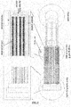
- FIG. 2 is an underside view showing one culture unit occupying three wells according to specific embodiments of the invention.
- the cell culture portion visible in the middle well is divided into four blocks, with each block having four separated cell culture channels surrounded by medium channels used for medium fluidic passage.
- these four separated cell culture channels may be preferred to as sinusoids or artificial sinusoids, regardless of whether the far end of the areas has a rounded shape. Separation into four blocks facilitates air diffusion through the material that defines the microfluidic channels (such as silicone elastomer polydime-thylsiloxane (PDMS)) structure into the culture areas.
- PDMS silicone elastomer polydime-thylsiloxane
- FIG. 3 is a close-up underside view illustrating details of the microfluidic cell culture areas described above according to specific embodiments of the invention.
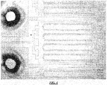
- FIG. 4 is a close up micrograph of a cell culture area illustrating two large air holes at the left of the figure each connected to an air passage that is placed between the blocks, each block having four cell culture sinusoids according to specific embodiments of the invention.
- FIG. 5 is a close up micrograph of a cell culture area illustrating two large air holes at the left of the figure each connected to an air passage that is placed between the blocks, each block having eight cell culture sinusoids according to specific embodiments of the invention.
- FIG. 6 illustrates high aspect ratio channels surrounding cell culture areas wherein channels between solid structures are approximately 4 ⁇ m wide and 40 ⁇ m tall to prevent cells from growing out.
- the channels in this example are separated by approximately 40 ⁇ m.
- FIG. 7A illustrates a cell inlet/media outlet of a modified cell culture area with a large rectangular cell inlet to provide for easier cell loading and with a cell loading perfusion area and a solid wall cell culture area.
- FIG. 7B illustrates the media inlet/cell culture area of a modified microfluidic cell culture system according to specific embodiments of the invention.
- cell loading is from the right and media flow, as indicated by the arrows, is from the left.
- perfusion passages are absent in a portion of the cell culture channel (or artificial sinusoid). This has been found to more easily locate cells at the end of the cell culture channel in the cell culture area.
- a portion of the cell culture channel near the fluid outlet has perfusion passages to ensure fluid flow after cells have aggregated at the culture end.
- the improved design provides for easier cell loading and a longer cell culture areas and cell culture channels to culture more cells and more uniform flow of nutrients.
- FIG. 8 is a schematic showing three blocks of four long cell culture sinusoids, where the long cell sinusoids extend across two wells, and further shows a rectangular cell inlet region / flow outlet region, and four air holes connecting to four air channels.
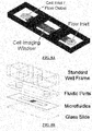
- FIG. 9A-B are simplified schematic diagrams illustrating in three dimensions the components of a multi cell (e.g., 3) microfluidic system including a representation of the well frame according to specific embodiments of the invention.
- a multi cell e.g., 3
- FIG. 9A-B are simplified schematic diagrams illustrating in three dimensions the components of a multi cell (e.g., 3) microfluidic system including a representation of the well frame according to specific embodiments of the invention.
- FIG. 10 is a simplified side view showing a structure according to specific embodiments of the invention illustrating two wells that are used in cell flow and fluid flow.
- FIG. 11 is a close-up micrograph showing cells loaded in five sinusoid cell culture regions with four sinusoid channels between according to specific embodiments of the invention.
- FIG. 12 shows four close-up micrographs showing cells loaded in four different sized sinusoid cell culture regions according to specific embodiments of the invention.
- the present invention provides a number of novel improved microfluidic configurations.
- three wells are used for each otherwise independent cell culture system.
- artificial sinusoids with artificial epithelial barriers are provided with just one (optionally shared or multiplexed) fluidic inlet and one (optionally shared or multiplexed) fluidic output, where the medium output also functions as a cellular input.
- artificial sinusoids with artificial epithelial barriers with just one fluidic inlet and one fluidic output are divided into blocks with air channels provided between blocks.
- air holes are provided in the well chamber above the cell culture area of a microfluidic cellular culture array, where the medium output also functions as a cellular input.
- a multiplexed medium inlet structure and multiplexed cellular input structure are provided to connect inputs and outputs to blocks of artificial sinusoids.
- a multiplexed medium inlet structure and larger shared cellular input structure are provided to connect inputs and outputs to blocks of artificial sinusoids.
- artificial sinusoids are configured with non-open portions of an epithelial barrier to better localize cells, and with perfusion inlets surrounding a cell culture area and optionally also present near a cell inlet area of the sinusoid.
- longer artificial sinusoid chambers are provided.
- the structures disclosed above can also be adapted to systems using more or fewer wells on a standard microtiter well plate, such as those described in referenced documents and in other examples herein.
- FIG. 13 is a schematic diagram showing steps from an empty culture region to performing a cell assay according to specific embodiments of the invention.
- Various novel aspects according to specific embodiments of the invention simplify these steps and allow them to be automated.
- Cell loading in specific embodiments of the invention can utilize the rapid surface tension flow between the cell inlet and the flow inlet.
- the cell inlet reservoir (upper and lower) is aspirated of its priming solution.
- the flow inlet upper reservoir is aspirated.
- An amount e.g., Five microliters
- cell suspension e.g., trypsinized HeLa human cancer cell line, 5x10 ⁇ 5 cells/ml
- the flow inlet lower reservoir is aspirated, causing liquid to flow from cell inlet to flow inlet via surface tension/capillary force.
- Cell loading in various configurations can be completed in approximately 2-5 minutes.
- the cell loading reservoir is then washed with medium (e.g., Dulbecco's Modified Eagle's Medium, DMEM) and filled with e.g., 50-100 microliters of clean medium.
- medium e.g., Dulbecco's Modified Eagle's Medium, DMEM
- the plate is was placed in a controlled culture environment for a period (e.g., 37C, 5% CO 2 incubator for 2-4 hours) to allow for cell attachment.
- a proprietary pneumatic manifold as described elsewhere herein, is mated to the plate and pneumatic pressure is applied to the cell inlet area for more effective cell loading.
- overall cell culture area design can be made more effective when it is not necessary to allow for passive cell loading.
- FIG. 14A-C shows a top view, side view, and plan view of a schematic of an example manifold according to specific embodiments of the invention.
- the eight tubing lines to the right are for compressed air, and each is configured to provide pressure to a column of cell inlet wells in a microfluidic array.
- the left-most line in the figure is for vacuum and connects to an outer vacuum ring around the manifold.
- Each column of wells is generally connected to a single pressure line with wells above imaging regions skipped.
- the manifold is placed on top of a standard well plate.
- a rubber gasket lies between the plate and manifold, with holes matching the manifold (not shown).
- the vacuum line creates a vacuum in the cavities between the wells, holding the plate and manifold together. Pressure is applied to the wells to drive liquid into the microfluidic channels (not shown). A typical pressure of 1 psi is used, therefore the vacuum strength is sufficient to maintain an air-tight seal.
- each column is connected to a single pressure line. Columns above the cell imaging regions are skipped.
- Pressurized cell loading in a system according to specific embodiments of the invention has been found to be particularly effective in preparing cultures of aggregating cells (e.g., solid tumor, liver, muscle, etc.). Pressurized cell loading also allows structures with elongated culture regions, e.g., as shown in FIG. 7 and FIG. 8 , to be effectively loaded.
- Use of a pressurized manifold for cell loading and passive flow for perfusion operations allows the invention to utilize a fairly simple two inlet design, without the need for additional inlet wells and/or valves as used in other designs.
- the format of the microfluidic plate design allows two automation-friendly flow modalities dependent on the extent of dispensing/aspiration.
- the first is surface tension mediated flow.
- the capillary force of the fluid/air interface along with the wetted surfaces glass, silicone, acrylic
- This effect is useful for microfluidic flows as it is only evident when the reservoir diameter is small and the flow volumes are small.
- the lower reservoir wells are 1-2 mm in diameter, and with a total flow volume of approximately 3-5 microliters. Since the microfluidic channel volume is only 0.2 microliters, this mechanism is well suited for cell loading and cell exposures.
- the second mechanism is gravity driven perfusion, which is well suited for longer term flows, as this is dependent on the liquid level difference and not the reservoir dimensions. According to specific embodiments of the invention, this may be accomplished by adding more liquid into one reservoir (typically filling near the top of the upper reservoir). The fluidic resistance through the microfluidic channels will determine how long (e.g., 24 hours) to reach equilibrium between the wells and thus determine how often wells should be refilled.
- FIG. 15 shows the flow rate difference between the surface tension mechanism and the gravity driven mechanism.
- the surface tension flow in an example, 5 microliters was dispensed into the lower reservoir followed by aspiration of the opposing lower reservoir.
- a liquid level difference of 2.5 mm was used, with both wells filled into the upper reservoir portion.
- the gravity perfusion rate is also responsive to the liquid level difference between the two upper reservoir wells as illustrated in FIG. 16 . This fact allows an automated dispenser/aspirator to control and maintain a given perfusion flow rate over a 10-fold range during culture. Here, different liquid level differences were produced via dispensing volumes and measured for volumetric flow rate.
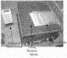
- the liquid height difference between the inlet/outlet wells across the plate can also be precisely controlled using a mechanical tilting platform.
- a mechanical tilting platform In this implementation, it is possible to maintain a constant flow rate over time, as well as back-and-forth flow with different forward and reverse times (i.e. blood flow).
- both inlet and outlet reservoirs were filled with 50 microliters of solution. On a flat surface, there is no flow through the channels, and as the angle is increased, so is the flow rate.
- the photo shows a prototype controlled tilting platform, consisting of a mechanical platform, and an electronic switch.
- perfusion cell culture can be initiated by filling the flow inlet reservoir with 200-300 microliters of fresh medium (e.g., DMEM supplemented with 10% fetal bovine serum) and aspirating the cell inlet upper reservoir.
- fresh medium e.g., DMEM supplemented with 10% fetal bovine serum
- the liquid level difference between the flow inlet and cell inlet wells will then cause a continuous gravity driven flow through the attached cells.
- the flow inlet well is refilled and the cell inlet well aspirated during a period depending on fluidic resistance and reservoir volumes (e.g., every 24 hours).
- Cell assay can be performed directly on the microfluidic cell culture using standard optically based reagent kits (e.g. fluorescence, absorbance, luminescence, etc.). For example a cell viability assay utilizing conversion of a substrate to a fluorescent molecule by live cells has been demonstrated (CellTiter Blue reagent by Promega Corporation).
- CellTiter Blue reagent by Promega Corporation.
- the reagent is dispensed into the flow inlet reservoir and exposed to the cells via gravity perfusion over a period of time (e.g., 21 hours).
- the new fluid can be added to the flow inlet reservoir followed by aspiration of the cell inlet reservoir.
- Data can be collected directly on the cells/liquid in the microfluidic plate, such as placing the plate into a standard fluorescence plate reader (e.g., Biotek Instruments Synergy 2 model).
- the substrate may diffuse into the outlet medium, and therefore be easily detected in the cell inlet reservoir.
- the plate can be placed on a scanning microscope or high content system.
- an automated Olympus IX71 invested microscope station can be used to capture viability of cultured liver cells with a 20X objective lens.
- cells By repeatedly filling/aspirating the wells, cells can be maintained for long periods of time with minimal effort (e.g. compared to standard "bioreactors" which require extensive sterile preparation of large fluid reservoirs that cannot be easily swapped out during operation).
- FIG. 18 illustrates a top view schematic of an example cell culture automation system according to specific embodiments of the invention.
- various "off-the-shelf" machines can be used to create an automated system. This schematic shows an example of how this is accomplished.
- a robotic arm (plate handler) moves the microfluidic plates from station to station.
- An automated incubator stores the plates at the proper temperature and gas environment for long term perfusion via gravity flow.
- the pipettor dispenses liquids (media, drugs, assay reagents, etc.) to the inlet wells and removes liquid from the outlet wells.
- a plate reader is used for assay.
- the cell loader is optionally used to introduce the cells to the microfluidic arrays at the beginning of the experiment.
- the cell loader in particular is generally not "off-the-shelf' and operates by applying pneumatic pressure to specified wells of the array plate to induce flow. Standard or custom computer software is available to integrate operations.
- FIG. 19 is a photograph of an example automated microfluidic perfusion array system according to specific embodiments of the invention.
- the basic process includes: 1) removing the plate from the incubator, 2) removing liquid from the outlet wells via the pipettor, 3) moving a media/drug storage plate from the "plate stacks," 4) transferring liquid from the media/drug plate to the microfluidic plate via the pipettor, 5) placing the microfluidic plate into the incubator, 6) repeat for each plate, 7) repeat after specified time interval (e.g. 24 hours).
- FIG. 20 is a flow chart illustrating the process flow of typical operation steps. This figure illustrates, as an example, automated process steps an indicates an automated device that is used to perform such a step.
- a standard automated pipettor is used for an optional surface coating, to add cells in suspension, to add media or drugs or reagents, and to change media.
- Known automated pipettors can individually deliver or withdraw fluids from specified wells.
- a proprietary cell loader is used to pressurize the cell inlet wells for cell loading. After a period in an incubator designed for optimal cell attachment, the cell loader can again be used to wash fluid and unattached cells from the microfluidic culture areas.
- One or more reading or analysis devices is used to assay the cells.
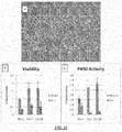
- FIG. 21 illustrates four microfluidic culture areas from an example array plate prepared in the example system described above using primary rat hepatocytes.
- the cells were cultured for 1 week with medium changed at a rate of 150ul per unit, twice a day. Cells were assayed at the end of 7 days for viability using the Cell Titer Blue Kit from Promega, and read on an automated fluorescence plate reader (Biotek Synergy).
- an example microfluidic culture area uses a grid flow-through epithelial walls.
- FIG. 22 illustrates a portion of a microfluidic culture area from an example array, plate prepared in the example system described above using primary human hepatocytes.
- the cells were cultured in the microfluidic array according to specific embodiments of the invention, showing (a) phase contrast of freshly isolated human hepatocytes cultured in the microfluidic device for 13 days.
- FIG. 23 illustrates a layout of another type of cell culture array designed for general cell culture automation according to specific embodiments of the invention.
- each culture unit consists of 4 well positions.
- the first well is for perfusion medium
- the second well is for cell inlet
- the third well is for imagine the microfluidic chamber
- the fourth well is the outlet.
- a cell barrier/perfusion barrier localizes cells to the cell area and improves nutrient transport during continuous perfusion culture.
- the low fluidic resistance of the cell inlet to outlet path enables cells to be rapidly loaded via gravity or surface tension methods without an external cell loading mechanism.
- the high fluidic resistance of the perfusion inlet channels allows long term continuous perfusion of medium via gravity flow without any external pump mechanism.
- FIG. 24 illustrates an operation schematic for performing automated cell culture and immunostaining on a microfluidic array with gravity cell loading as described above.
- Example applications include stem cell culture and primary cell culture with immunofluorescence staining and microscopy.
- FIG. 25 illustrates an alternative example SBS (Society for Biomolecular Screening) standard microfluidic bioreactor array schematic.
- SBS Society for Biomolecular Screening
- FIG. 26A-B illustrate an alternative cellular culture system assembly according to specific embodiments of the present invention showing (A) an example schematic microfluidic design for three cell units; (B) a soft lithography fabrication of this design with laser machining of four openings per culture unit. This design is attached to a microplate with wells for receiving medium and cells as described herein.
- FIG. 27 illustrates operation steps of a less automated or prototype system according to specific embodiments of the invention.
- the 96-well plate standard allows the microfluidic system to be operated using standard techniques and equipment. For example, liquid dispensing is achieved with standard pipette mechanics, and cell culture and analysis is compatible with existing incubators and plate readers.
- a custom built cell loading system can be used to load the cells using air pressure as described above.
- the gravity driven flow culture configuration utilizes the medium level difference between the inlet and outlet well as well as engineering the fluidic resistances to achieve the desirable flow rate in nL/min regime. This provides the significant advantage of being able to "passively" flow culture medium for long periods of time (for example, up to 4 days) without the use of bulky external pumps.
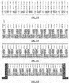
- FIG. 30 is a block diagram illustrating two components of a direct soft molding process according to specific embodiments of the invention.
- the two components illustrated are: (1) An injection molded top piece made of acrylic containing at least alignment marks (to be assembled to the microfluidic mold) and well structures generally complying with standard microtiter plate formats. (Alternatively, a standard well plate may be used.) (2) A microfluidic mold fabricated using semiconductor technologies on a 6" silicon wafer containing the microfluidic cell culture arrays made of epoxy or electroplated metals, as well as the alignment marks so the well structures aligned to the microfluidic structures during the molding process.
- An injection molded top piece is made of acrylic or any similar suitable material and contains well structures that preferably comply with standard microtiter plate formats as will be discussed more herein.
- a microfluidic mold fabricated using any known semiconductor and/or microfabrication technologies on, for example, a 6" silicon wafer.
- the mold contains an impression the microfluidic cell culture arrays and can include components made of epoxy or electroplated metals, as well as the alignment marks so the well structures aligned to the microfluidic structures during the molding process.
- the mold is coated with fluoropolymer to reduce stiction of the soft polymer to the mold.
- the bottom of the wells can be flat, rounded or tapered.
- the bottom of the top piece, which covers the microfluidic structures is as flat as practically to assist uniform molding across the array.
- the bottom of the top piece can be chemically or mechanically or otherwise modified or primed by a reagent (such as Sylgard Primecoat) or an abrasive surface (sanding) or laser so the soft polymers adhere to the bottom of the top piece after the molding process. This treatment of the surface is indicated by the heavy line.
- FIG. 31B illustrates an example wherein an appropriate amount of soft polymer is poured onto the center of the mold (usually a few milliliters, depending on the area to be covered as well as the thickness of the soft polymer after molding).
- the top piece and the mold are sandwiched between two pieces of flat surfaces (usually glass plates) with clamping mechanisms (in this case, magnets).
- FIG. 31C illustrates an example wherein the clamping mechanism holds the top piece and the mold together with alignment marks fitted to each other.
- the soft polymer is then cured, for example by temperature or UV light of otherwise so the microfluidic cell culture array is truthfully molded onto the soft polymer.
- elevated temperature usually 60 C for at least 2 hours.
- FIG. 31D illustrates an example wherein after detaching the molded microfluidic cell culture array with the top piece, a laser cutter is used to create fluidic connections between the microfluidic structures and the wells at specific locations (cell/reagent inlets/outlets).
- the circular top piece is trimmed to rectangular shape at this stage. (Note that in this image, the structure is inverted.)
- the molded piece Before enclosing the bottom of the microfluidic cell culture array, the molded piece is ultrasonically cleaned to shake off any dust created by the laser cutting step. A top piece may be trimmed to a rectangular shape at this stage.
- the cross section shown in through each of the fluidic connections for illustration purposes, though the laser only makes holes in the material and does not cut the wells apart.
- the molded piece is preferably ultrasonically or otherwise cleaned to shake off any dust created by the laser cutting step.
- FIG. 31E illustrates an example wherein the microfluidic cell culture array undergoes oxygen plasma treatment and is bonded to a piece of rectangular glass.
- FIG. 31F illustrates an example wherein using a liquid dispenser, the microfluidic cell culture array is filled with priming solutions to maintain its modified surface chemistry. If bubbles appear to be trapped inside the array, placement in a vacuum chamber may be used to eliminate the bubbles.
- FIG. 31G illustrates an example wherein to prevent liquid evaporation, the array is sealed with a tape.
- FIG. 31H illustrates an example wherein the array is fit into a frame so the finished array can be treated like a standard microtiter plate with the correct outside dimensions.
- FIG. 32A-C illustrate three components of a direct soft molding process according to specific embodiments of the invention.
- (A) shows an injection molded top piece that includes well structures complying with standard microtiter plate formats.
- a standard microtiter plate may be used as the top piece that includes well structures complying with standard microtiter plate formats.
- (B) Illustrates a 1.5mm thick acrylic circular sheet (6" in diameter)
- (C) illustrates a microfluidic mold fabricated on a 6" silicon wafer containing microfluidic cell culture units (in this example 8 x 4 units) in an arrays made of epoxy, etched silicon, or electroplated metals, as well as a spacer to control the minimum thickness of the soft polymer after molding.
- the mold is coated with fluoropolymer to reduce stiction of the soft polymer to the mold.
- the microfluidic mold is glued to a 1mm thick soda lime glass (7" x 7") with four magnets (e.g., 15mm in diameter and 1.5mm in thickness) glued to the four corners of the glass.
- the other piece of the 1mm thick soda lime glass (7" x 7") with complementary magnets is prepared in similar fashion ( FIG. 32D ) with the magnets of opposite polarity glued on the four corners so the magnets will self-align onto the magnets in FIG. 32C .
- One side of the acrylic sheet is chemically modified by a reagent (e.g., Sylgard Primecoat) to induce the strong adhesion between the acrylic and the soft polymer (e.g., Sylgard 184) to be used during the molding process.
- a reagent e.g., Sylgard Primecoat
- FIG. 33A illustrates a step wherein an appropriate amount of soft polymer is poured onto the center of the mold (usually a few milliliters, depending on the area to be covered as well as the spacer thickness) For example, for a mold 6" in diameter and a 150micron spacer, the minimum amount required is n x 7.62cm x 7.62cm x 0.015cm ⁇ 2.75mL).
- FIG. 33B illustrates a step wherein the acrylic sheet is sandwiched between two pieces of the glass plates so the magnets will press the acrylic sheet (with primer modified surface facing the mold) against the mold until the acrylic sheet hit the spacer.
- the soft polymer will then fill the space between the acrylic sheet and the mold to replicate the microfluidic structures.
- the magnet-assisted clamping mechanism holds the pieces together while the soft polymer is cured at elevated temperature (60 degreeC) for at least 2 hours.
- the acrylic sheet with the soft polymer is detached from the mold and a microfluidic cell culture array as described herein is truthfully molded onto the soft polymer.
- a surface protection tape e.g., Ultron Blue Adhesive Plastic Film 80micron
- Ultron Blue Adhesive Plastic Film 80micron is optionally applied to the top of the surface of the elastomer by a roller.
- FIG. 33D illustrates a step wherein a CO2 laser cutter (VersaLaser, 25W model) is used to create fluidic connections between the microfluidic structures and the injection molded wells (cell inlet and medium inlet). Since the soft polymer used in the process is gas permeable, "air holes" are cut near the cell culture areas to promote air diffusion for better cell culture. The circular top piece may be trimmed to rectangular shape at this stage. The surface protection tape is removed and the array is ultrasonically cleaned (or water-jet cleaned) to shake off any dust created by the laser cutting step and a new surface protection tape is applied.
- a CO2 laser cutter VeryLaser, 25W model
- the microfluidic cell culture array is glued to the injection molded plate or a standard-well plate with an ultra-violet (UV) curable glue which is also bio-compatible (Loctite 3301).
- UV ultra-violet
- the plate with the microfluidic cell culture array is cured in a UV chamber for 30 minutes.
- both a glass substrate (White Float Glass) and the microfluidic cell culture array undergo oxygen plasma treatment to activate the surface.
- the glass substrate encloses the microfluidic cell culture array through covalent bonding, as shown in FIG. 33F .
- the microfluidic cell culture array is filled with priming solutions as shown in FIG. 33G .
- the array is generally placed inside a vacuum chamber for bubbles removal.
- the plate may also be placed inside a UV/Ozone chamber (Novascan) for sterilization.
- the array is sealed with a tape (e.g., Excel Scientific, AlumaSeal) as shown in FIG. 33H .
- Integrated systems for the collection and analysis of cellular and other data as well as for the compilation, storage and access of the databases of the invention typically include a digital computer with software including an instruction set for sequence searching and/or analysis, and, optionally, one or more of high-throughput sample control software, image analysis software, collected data interpretation software, a robotic control armature for transferring solutions from a source to a destination (such as a detection device) operably linked to the digital computer, an input device (e.g., a computer keyboard) for entering subject data to the digital computer, or to control analysis operations or high throughput sample transfer by the robotic control armature.
- the integrated system further comprises valves, concentration gradients, fluidic multiplexors and/or other microfluidic structures for interfacing to a microchamber as described.
- the present invention can comprise a set of logic instructions (either software, or hardware encoded instructions) for performing one or more of the methods as taught herein.
- software for providing the data and/or statistical analysis can be constructed by one of skill using a standard programming language such as Visual Basic, Fortran, Basic, Java, or the like.
- a standard programming language such as Visual Basic, Fortran, Basic, Java, or the like.
- Such software can also be constructed utilizing a variety of statistical programming languages, toolkits, or libraries.
- FIG. 34 shows an information appliance (or digital device) 700 that may be understood as a logical apparatus that can read instructions from media 717 and/or network port 719, which can optionally be connected to server 720 having fixed media 722. Apparatus 700 can thereafter use those instructions to direct server or client logic, as understood in the art, to embody aspects of the invention.
- One type of logical apparatus that may embody the invention is a computer system as illustrated in 700, containing CPU 707, optional input devices 709 and 711, disk drives 715 and optional monitor 705.
- Fixed media 717, or fixed media 722 over port 719 may be used to program such a system and may represent a disk-type optical or magnetic media, magnetic tape, solid state dynamic or static memory, etc.
- the invention may be embodied in whole or in part as software recorded on this fixed media.
- Communication port 719 may also be used to initially receive instructions that are used to program such a system and may represent any type of communication connection.
Landscapes
- Chemical & Material Sciences (AREA)
- Health & Medical Sciences (AREA)
- Engineering & Computer Science (AREA)
- Life Sciences & Earth Sciences (AREA)
- Wood Science & Technology (AREA)
- Organic Chemistry (AREA)
- Bioinformatics & Cheminformatics (AREA)
- Zoology (AREA)
- General Health & Medical Sciences (AREA)
- Analytical Chemistry (AREA)
- Biochemistry (AREA)
- General Engineering & Computer Science (AREA)
- Sustainable Development (AREA)
- Microbiology (AREA)
- Biotechnology (AREA)
- Biomedical Technology (AREA)
- Genetics & Genomics (AREA)
- Clinical Laboratory Science (AREA)
- Dispersion Chemistry (AREA)
- Physics & Mathematics (AREA)
- Chemical Kinetics & Catalysis (AREA)
- Hematology (AREA)
- Pathology (AREA)
- Immunology (AREA)
- General Physics & Mathematics (AREA)
- Computer Hardware Design (AREA)
- Fluid Mechanics (AREA)
- Robotics (AREA)
- Apparatus Associated With Microorganisms And Enzymes (AREA)
Applications Claiming Priority (4)
| Application Number | Priority Date | Filing Date | Title |
|---|---|---|---|
| US1888208P | 2008-01-03 | 2008-01-03 | |
| US3729708P | 2008-03-17 | 2008-03-17 | |
| EP09701350.2A EP2245453B1 (fr) | 2008-01-03 | 2009-01-05 | Système microfluidique en réseau de culture de cellules pour tests automatisés et procédés de fonctionnement de celui-ci |
| PCT/US2009/030168 WO2009089189A2 (fr) | 2008-01-03 | 2009-01-05 | Système en réseau de culture de cellules pour tests automatisés et procédés de fonctionnement et de fabrication de celui-ci |
Related Parent Applications (2)
| Application Number | Title | Priority Date | Filing Date |
|---|---|---|---|
| EP09701350.2A Division EP2245453B1 (fr) | 2008-01-03 | 2009-01-05 | Système microfluidique en réseau de culture de cellules pour tests automatisés et procédés de fonctionnement de celui-ci |
| EP09701350.2A Division-Into EP2245453B1 (fr) | 2008-01-03 | 2009-01-05 | Système microfluidique en réseau de culture de cellules pour tests automatisés et procédés de fonctionnement de celui-ci |
Publications (2)
| Publication Number | Publication Date |
|---|---|
| EP3173787A1 true EP3173787A1 (fr) | 2017-05-31 |
| EP3173787B1 EP3173787B1 (fr) | 2021-06-02 |
Family
ID=40853733
Family Applications (2)
| Application Number | Title | Priority Date | Filing Date |
|---|---|---|---|
| EP09701350.2A Active EP2245453B1 (fr) | 2008-01-03 | 2009-01-05 | Système microfluidique en réseau de culture de cellules pour tests automatisés et procédés de fonctionnement de celui-ci |
| EP16185733.9A Active EP3173787B1 (fr) | 2008-01-03 | 2009-01-05 | Système de réseau de culture de cellules pour épreuves automatisées et procédés de fonctionnement et de fabrication de celui-ci |
Family Applications Before (1)
| Application Number | Title | Priority Date | Filing Date |
|---|---|---|---|
| EP09701350.2A Active EP2245453B1 (fr) | 2008-01-03 | 2009-01-05 | Système microfluidique en réseau de culture de cellules pour tests automatisés et procédés de fonctionnement de celui-ci |
Country Status (4)
| Country | Link |
|---|---|
| US (2) | US9376658B2 (fr) |
| EP (2) | EP2245453B1 (fr) |
| ES (2) | ES2882661T3 (fr) |
| WO (1) | WO2009089189A2 (fr) |
Families Citing this family (39)
| Publication number | Priority date | Publication date | Assignee | Title |
|---|---|---|---|---|
| US8257964B2 (en) | 2006-01-04 | 2012-09-04 | Cell ASIC | Microwell cell-culture device and fabrication method |
| US9376658B2 (en) | 2008-01-03 | 2016-06-28 | Emd Millipore Corporation | Cell culture array system for automated assays and methods of operation and manufacture thereof |
| WO2007008609A2 (fr) | 2005-07-07 | 2007-01-18 | The Regents Of The University Of California | Methodes et dispositif pour reseau de culture cellulaire |
| US9388374B2 (en) | 2005-07-07 | 2016-07-12 | Emd Millipore Corporation | Microfluidic cell culture systems |
| US9354156B2 (en) * | 2007-02-08 | 2016-05-31 | Emd Millipore Corporation | Microfluidic particle analysis method, device and system |
| US9637715B2 (en) * | 2005-07-07 | 2017-05-02 | Emd Millipore Corporation | Cell culture and invasion assay method and system |
| KR101150444B1 (ko) * | 2006-09-22 | 2012-06-01 | 아비소 게엠베하 메카트로닉 시스템 | 세포 및/또는 세포 군체의 자동 제거를 위한 방법 및 장치 |
| CN104328050B (zh) | 2008-07-16 | 2017-12-15 | 儿童医疗中心有限公司 | 具有微通道的器官模仿装置及其使用和制造方法 |
| US20110004304A1 (en) * | 2009-03-20 | 2011-01-06 | Tao Sarah L | Culturing retinal cells and tissues |
| US9353342B2 (en) | 2010-01-21 | 2016-05-31 | Emd Millipore Corporation | Cell culture and gradient migration assay methods and devices |
| US9261496B2 (en) | 2010-09-29 | 2016-02-16 | Massachusetts Institute Of Technology | Device for high throughput investigations of multi-cellular interactions |
| US10114020B2 (en) * | 2010-10-11 | 2018-10-30 | Mbio Diagnostics, Inc. | System and device for analyzing a fluidic sample |
| US10526572B2 (en) | 2011-04-01 | 2020-01-07 | EMD Millipore Corporaticn | Cell culture and invasion assay method and system |
| JP6232383B2 (ja) | 2011-12-03 | 2017-11-15 | イー・エム・デイー・ミリポア・コーポレイシヨン | マイクロ流体の細胞培養のためのマイクロインキュベーションシステムおよび方法 |
| US9725687B2 (en) | 2011-12-09 | 2017-08-08 | President And Fellows Of Harvard College | Integrated human organ-on-chip microphysiological systems |
| WO2014070235A1 (fr) | 2012-10-29 | 2014-05-08 | Mbio Diagnostics, Inc. | Système d'identification de particules biologiques, cartouche et procédés associés |
| US9932550B2 (en) | 2012-11-27 | 2018-04-03 | Cfd Research Corporation | Multi-chambered cell culture device to model organ microphysiology |
| CA2895638A1 (fr) | 2013-03-15 | 2014-09-18 | Fluidigm Corporation | Procedes et dispositifs pour l'analyse de combinaisons multicellulaires definies |
| US10465158B2 (en) * | 2013-07-12 | 2019-11-05 | President And Fellows Of Harvard College | Systems and methods for cell culture device interconnection and fluidic device interconnection |
| US10981167B2 (en) | 2015-03-18 | 2021-04-20 | The Broad Institute, Inc. | Massively parallel on-chip coalescence of microemulsions |
| CN109069870B (zh) | 2016-02-24 | 2022-04-29 | 洛克菲勒大学 | 基于胚胎细胞的用于亨廷顿氏病的治疗候选物筛选系统、模型及它们的应用 |
| WO2017181258A1 (fr) * | 2016-04-21 | 2017-10-26 | Duane Hewitt | Système de flux continu |
| JP6826200B2 (ja) * | 2017-01-19 | 2021-02-03 | エッセン インストゥルメンツ,インコーポレイテッド ディー/ビー/エー エッセン バイオサイエンス,インコーポレイテッド | マイクロプレート実験器具の灌流および環境制御のための方法および装置 |
| US11926814B2 (en) | 2017-08-23 | 2024-03-12 | Northwestern University | Multi-chamber fluidic platform |
| US11911764B2 (en) | 2018-02-21 | 2024-02-27 | Nexcelom Bioscience Llc | System and method for cell imaging, analysis and measurement |
| US10775395B2 (en) * | 2018-10-18 | 2020-09-15 | Arctoris Limited | System and method of performing a biological experiment with adaptive cybernetic control of procedural conditions |
| US11273445B2 (en) * | 2018-11-05 | 2022-03-15 | Daegu Gyeongbuk Institute Of Science And Technology | Biomimetic chip device |
| FR3094012B1 (fr) | 2019-03-20 | 2022-08-12 | Cherry Biotech Sas | Procédé d'enrichissement en gaz et simultanément de déplacement d’un fluide et dispositif pour le contrôle de l'environnement cellulaire sur une plaque de culture cellulaire multipuits correspondant. |
| EP3953044A4 (fr) * | 2019-04-08 | 2022-06-01 | Technion Research & Development Foundation Limited | Réseau multiplexé de dispositifs de réseau de gouttelettes de l'ordre du nanolitre |
| CN110729200A (zh) * | 2019-09-24 | 2020-01-24 | 杭州臻镭微波技术有限公司 | 一种控制散热器流量的三维异构模组制作方法 |
| US11807842B2 (en) * | 2019-09-30 | 2023-11-07 | Biopico Systems Inc | Fluidic array systems and testing for cells, organoids, and organ cultures |
| CN114585721A (zh) * | 2019-10-30 | 2022-06-03 | 安捷伦科技有限公司 | 用于细胞培养孔板的方法和装置 |
| EP3907275A1 (fr) | 2020-05-08 | 2021-11-10 | Technische Universität Wien | Dispositif microfluidique |
| EP4015619A1 (fr) * | 2020-12-17 | 2022-06-22 | Leica Microsystems CMS GmbH | Ensemble microplaque et procédé de transfert d'échantillon au moyen d'un ensemble microplaque |
| WO2022155257A1 (fr) * | 2021-01-12 | 2022-07-21 | Berkeley Lights, Inc. | Systèmes, appareils et procédés de fabrication d'agents thérapeutiques cellulaires |
| CN112938465A (zh) * | 2021-01-21 | 2021-06-11 | 珠海市运泰利自动化设备有限公司 | 保压上下料系统的控制方法 |
| US20230095466A1 (en) * | 2021-09-24 | 2023-03-30 | 3D Systems, Inc. | Manifolds, systems and methods for conducting biological studies under flow |
| EP4481029A1 (fr) | 2023-06-22 | 2024-12-25 | Cherry Biotech SAS | Procédé de régulation du déplacement de fluide et de la composition de gaz(s) et/ou du ph dans un dispositif de culture cellulaire et système de culture cellulaire correspondant |
| WO2025264814A1 (fr) * | 2024-06-21 | 2025-12-26 | Lonza Biologics Plc | Système de culture cellulaire miniaturisé pour l'étape de traitement de perfusion mimétique |
Citations (4)
| Publication number | Priority date | Publication date | Assignee | Title |
|---|---|---|---|---|
| US1985708A (en) | 1932-08-02 | 1934-12-25 | Oscar U Zerk | Shackle mechanism |
| US20040229349A1 (en) | 2002-04-01 | 2004-11-18 | Fluidigm Corporation | Microfluidic particle-analysis systems |
| WO2007008609A2 (fr) * | 2005-07-07 | 2007-01-18 | The Regents Of The University Of California | Methodes et dispositif pour reseau de culture cellulaire |
| US20070275455A1 (en) * | 2006-01-04 | 2007-11-29 | Hung Paul J | Valved, microwell cell-culture device and method |
Family Cites Families (167)
| Publication number | Priority date | Publication date | Assignee | Title |
|---|---|---|---|---|
| US3915679A (en) | 1973-04-16 | 1975-10-28 | Pall Corp | Vortex air cleaner array |
| US4055613A (en) | 1974-10-23 | 1977-10-25 | Akrosil Corporation | Production of three-dimensional designs |
| GB1539263A (en) | 1976-11-19 | 1979-01-31 | Toray Industries | Apparatus and methods for growing cells |
| DE3409501A1 (de) | 1984-03-15 | 1985-10-24 | Sandoz-Patent-GmbH, 7850 Lörrach | Verfahren zur kultivierung von zellen |
| US4748124A (en) | 1984-10-30 | 1988-05-31 | E. I. Du Pont De Nemours And Company | Compartmentalized cell-culture device and method |
| US4661455A (en) | 1986-01-16 | 1987-04-28 | Dorr-Oliver Incorporated | Membrane cell culturing device |
| US4734373A (en) | 1986-06-24 | 1988-03-29 | Bartal Arie H | Apparatus for enhancing cell growth, preservation and transport |
| US5786215A (en) | 1987-05-20 | 1998-07-28 | Baxter International Inc. | Method for culturing animal cells |
| US5153131A (en) | 1990-12-11 | 1992-10-06 | The United States Of America As Represented By The Administrator Of The National Aeronautics And Space Administration | High aspect reactor vessel and method of use |
| US5079168A (en) | 1988-08-10 | 1992-01-07 | Endotronics, Inc. | Cell culture apparatus |
| US5416022A (en) | 1988-08-10 | 1995-05-16 | Cellex Biosciences, Inc. | Cell culture apparatus |
| EP0402718B1 (fr) | 1989-06-03 | 1994-11-02 | Kanegafuchi Kagaku Kogyo Kabushiki Kaisha | Dispositif de contrôle de cellules |
| FR2660323B1 (fr) | 1990-03-30 | 1992-07-24 | Bertin & Cie | Dispositif de culture cellulaire. |
| SE470347B (sv) | 1990-05-10 | 1994-01-31 | Pharmacia Lkb Biotech | Mikrostruktur för vätskeflödessystem och förfarande för tillverkning av ett sådant system |
| US5310676A (en) | 1991-11-15 | 1994-05-10 | A/S Nunc | Cell cultivating device |
| DE4206585C2 (de) | 1992-03-03 | 1994-11-24 | Augustinus Dr Med Bader | Vorrichtung zur Massenkultur von Zellen |
| US5637469A (en) * | 1992-05-01 | 1997-06-10 | Trustees Of The University Of Pennsylvania | Methods and apparatus for the detection of an analyte utilizing mesoscale flow systems |
| US5330908A (en) | 1992-12-23 | 1994-07-19 | The United States Of America As Represented By The Administrator, National Aeronautics And Space Administration | High density cell culture system |
| US5424209A (en) | 1993-03-19 | 1995-06-13 | Kearney; George P. | Automated cell culture and testing system |
| US5462874A (en) | 1993-06-23 | 1995-10-31 | Wolf; Martin L. | Dialyzed multiple well tissue culture plate |
| US5686301A (en) | 1993-09-02 | 1997-11-11 | Heraeus Instruments Gmbh | Culture vessel for cell cultures |
| US5702941A (en) | 1993-09-09 | 1997-12-30 | Synthecon, Inc. | Gas permeable bioreactor and method of use |
| US5437998A (en) | 1993-09-09 | 1995-08-01 | Synthecon, Inc. | Gas permeable bioreactor and method of use |
| US5763279A (en) | 1993-09-09 | 1998-06-09 | Synthecon, Inc. | Gas permeable bioreactor and method of use |
| US5451524A (en) | 1994-02-01 | 1995-09-19 | The Gillette Company | In vitro chamber for human organ tissue samples |
| US5882918A (en) | 1995-08-08 | 1999-03-16 | Genespan Corporation | Cell culture incubator |
| US5793440A (en) | 1994-03-18 | 1998-08-11 | Sony Corporation | Key signal processing apparatus for video signal processing |
| US5565353A (en) | 1994-06-22 | 1996-10-15 | Board Of Regents, The University Of Texas System | Perfusable culture device |
| US5714384A (en) | 1994-06-28 | 1998-02-03 | Wilson; John R. | Compartmentalized tissue culture bag |
| US5693537A (en) | 1994-06-28 | 1997-12-02 | Wilson; John R. | Compartmentalized tissue culture flask |
| GB9413029D0 (en) | 1994-06-29 | 1994-08-17 | Common Services Agency | Stem cell immobilisation |
| US6297046B1 (en) | 1994-10-28 | 2001-10-02 | Baxter International Inc. | Multilayer gas-permeable container for the culture of adherent and non-adherent cells |
| DE19537774C2 (de) | 1994-11-18 | 1996-09-19 | Heraeus Instr Gmbh | Verfahren zur Zellkultivierung und Vorrichtung zur Durchführung des Verfahrens |
| US5641644A (en) | 1994-12-09 | 1997-06-24 | Board Of Regents, The University Of Texas System | Method and apparatus for the precise positioning of cells |
| EP0725134A3 (fr) | 1995-02-03 | 1998-05-13 | NPBI Nederlands Produktielaboratorium voor Bloedtransfusieapparatuur en Infusievloeistoffen B.V. | Bioréacteur flexible pour cellules thérapeutiques |
| CA2175626C (fr) | 1995-05-18 | 1999-08-03 | Timothy A. Stevens | Fiole pour culture tissulaire |
| US6238908B1 (en) | 1995-06-07 | 2001-05-29 | Aastrom Biosciences, Inc. | Apparatus and method for maintaining and growth biological cells |
| US6228635B1 (en) | 1995-06-07 | 2001-05-08 | Aastrom Bioscience, Inc. | Portable cell growth cassette for use in maintaining and growing biological cells |
| US6096532A (en) | 1995-06-07 | 2000-08-01 | Aastrom Biosciences, Inc. | Processor apparatus for use in a system for maintaining and growing biological cells |
| US5856174A (en) | 1995-06-29 | 1999-01-05 | Affymetrix, Inc. | Integrated nucleic acid diagnostic device |
| US5602028A (en) | 1995-06-30 | 1997-02-11 | The University Of British Columbia | System for growing multi-layered cell cultures |
| US5627070A (en) | 1995-07-26 | 1997-05-06 | Celltherapy, Inc. | Cell growing device for in vitro cell population expansion |
| US5686304A (en) | 1995-12-15 | 1997-11-11 | Avecor Cardiovascular, Inc. | Cell culture apparatus and method |
| ATE203106T1 (de) | 1996-03-05 | 2001-07-15 | Syngenta Participations Ag | Testsystem für chemische stoffe oder stoffgemische |
| US5942443A (en) * | 1996-06-28 | 1999-08-24 | Caliper Technologies Corporation | High throughput screening assay systems in microscale fluidic devices |
| US6429025B1 (en) * | 1996-06-28 | 2002-08-06 | Caliper Technologies Corp. | High-throughput screening assay systems in microscale fluidic devices |
| US6039897A (en) | 1996-08-28 | 2000-03-21 | University Of Washington | Multiple patterned structures on a single substrate fabricated by elastomeric micro-molding techniques |
| US5801054A (en) | 1996-09-19 | 1998-09-01 | The United States Of America As Represented By The Secretary Of The Air Force | Cell culture vessel with self-maintained atmosphere |
| CN1105914C (zh) * | 1997-04-25 | 2003-04-16 | 卡钳技术有限公司 | 改进了通道几何结构的微型流体装置 |
| US5932315A (en) | 1997-04-30 | 1999-08-03 | Hewlett-Packard Company | Microfluidic structure assembly with mating microfeatures |
| DE19719751A1 (de) | 1997-05-10 | 1998-11-12 | Augustinus Dr Med Bader | Vorrichtung zum Züchten und/oder Behandeln von Zellen |
| US6548263B1 (en) | 1997-05-29 | 2003-04-15 | Cellomics, Inc. | Miniaturized cell array methods and apparatus for cell-based screening |
| US7160687B1 (en) | 1997-05-29 | 2007-01-09 | Cellomics, Inc. | Miniaturized cell array methods and apparatus for cell-based screening |
| US6107085A (en) | 1997-07-11 | 2000-08-22 | Corning Incorporated | Self contained cell growth system |
| JP3761676B2 (ja) | 1997-07-11 | 2006-03-29 | 株式会社メニコン | 細胞培養用容器 |
| US5876675A (en) * | 1997-08-05 | 1999-03-02 | Caliper Technologies Corp. | Microfluidic devices and systems |
| US6190913B1 (en) | 1997-08-12 | 2001-02-20 | Vijay Singh | Method for culturing cells using wave-induced agitation |
| US6794184B1 (en) | 1998-01-19 | 2004-09-21 | Ulrich Mohr | Culturing device and method for culturing cells or tissue components |
| US6857449B1 (en) * | 1998-01-20 | 2005-02-22 | Caliper Life Sciences, Inc. | Multi-layer microfluidic devices |
| US6167910B1 (en) * | 1998-01-20 | 2001-01-02 | Caliper Technologies Corp. | Multi-layer microfluidic devices |
| US6756019B1 (en) * | 1998-02-24 | 2004-06-29 | Caliper Technologies Corp. | Microfluidic devices and systems incorporating cover layers |
| US6251343B1 (en) * | 1998-02-24 | 2001-06-26 | Caliper Technologies Corp. | Microfluidic devices and systems incorporating cover layers |
| WO1999047922A2 (fr) | 1998-03-18 | 1999-09-23 | Massachusetts Institute Of Technology | Ensemble de micro-tissus et de micro-organes vascularises et perfuses |
| US20040202579A1 (en) | 1998-05-08 | 2004-10-14 | Anders Larsson | Microfluidic device |
| US6518035B1 (en) | 1998-06-02 | 2003-02-11 | Rosetta Inpharmatics, Inc. | Targeted methods of drug screening using co-culture methods |
| US7155344B1 (en) * | 1998-07-27 | 2006-12-26 | Caliper Life Sciences, Inc. | Distributed database for analytical instruments |
| GB9817995D0 (en) * | 1998-08-19 | 1998-10-14 | Griffith John D | A surgical sewing device |
| DE69907249T2 (de) | 1998-10-08 | 2004-01-29 | Astrazeneca Ab | Mikrofabrizierter zellinjektor |
| US6637463B1 (en) | 1998-10-13 | 2003-10-28 | Biomicro Systems, Inc. | Multi-channel microfluidic system design with balanced fluid flow distribution |
| GB9912641D0 (en) | 1999-05-28 | 1999-07-28 | Ashby Scient Ltd | Textured and porous silicone rubber |
| US6548299B1 (en) | 1999-11-12 | 2003-04-15 | Mark J. Pykett | Lymphoid tissue-specific cell production from hematopoietic progenitor cells in three-dimensional devices |
| DE60045917D1 (de) | 1999-02-23 | 2011-06-16 | Caliper Life Sciences Inc | Sequenzierung durch inkorporation |
| WO2000050871A1 (fr) | 1999-02-26 | 2000-08-31 | Orchid Biosciences, Inc. | Microstructures destinees a etre utilisees dans des dosages et des reactions biologiques |
| US6410309B1 (en) | 1999-03-23 | 2002-06-25 | Biocrystal Ltd | Cell culture apparatus and methods of use |
| US6455310B1 (en) | 1999-03-23 | 2002-09-24 | Biocrystal Ltd. | Cell culture apparatus and method for culturing cells |
| GB9907665D0 (en) | 1999-04-01 | 1999-05-26 | Cambridge Molecular Tech | Fluidic devices |
| IL147207A0 (en) | 1999-06-21 | 2002-08-14 | Gen Hospital Corp | Methods and devices for culturing cells |
| WO2000078920A1 (fr) * | 1999-06-21 | 2000-12-28 | The General Hospital Corporation | Procedes et dispositifs de culture cellulaire et systemes d'assitance d'organes |
| TWI233449B (en) | 1999-07-01 | 2005-06-01 | Ind Tech Res Inst | High efficient cell-cultivating device |
| US6495104B1 (en) * | 1999-08-19 | 2002-12-17 | Caliper Technologies Corp. | Indicator components for microfluidic systems |
| US6837985B2 (en) | 1999-09-20 | 2005-01-04 | Aeromet Technologies, Inc. | External counter electrode |
| DE19947496C2 (de) | 1999-10-01 | 2003-05-22 | Agilent Technologies Inc | Mikrofluidischer Mikrochip |
| DE19948087B4 (de) | 1999-10-06 | 2008-04-17 | Evotec Ag | Verfahren zur Herstellung eines Reaktionssubstrats |
| FR2803852B1 (fr) | 2000-01-17 | 2004-11-05 | Farzin Sarem | Dispositif de culture cellulaire et tissulaire a circulation de fluide de culture controlee |
| MXPA02008290A (es) * | 2000-02-23 | 2004-09-10 | Caliper Technologies Inc | Sistema de control de presion de multi-reserva-. |
| US6593136B1 (en) | 2000-03-20 | 2003-07-15 | Geo-Centers, Inc. | Culturing cells in a chamber in a stack of chambers |
| US7867763B2 (en) * | 2004-01-25 | 2011-01-11 | Fluidigm Corporation | Integrated chip carriers with thermocycler interfaces and methods of using the same |
| US7323143B2 (en) | 2000-05-25 | 2008-01-29 | President And Fellows Of Harvard College | Microfluidic systems including three-dimensionally arrayed channel networks |
| US6569675B2 (en) | 2000-06-16 | 2003-05-27 | Corning Incorporated | Cell cultivating flask and method for using the cell cultivating flask |
| DE60013585T2 (de) | 2000-07-19 | 2005-09-15 | Technodop Ltd. (Société de Droit Irlandais) | Kulturraum und Bioreaktor zur ausserkörperlichen Tierzellenkultur |
| JP4273643B2 (ja) | 2000-08-08 | 2009-06-03 | 味の素株式会社 | 好気性培養における培養装置及び消泡制御方法 |
| DE10046175A1 (de) | 2000-09-19 | 2002-03-28 | Augustinus Bader | Verfahren und Vorrichtung zum Züchten und/oder Behandeln von Zellen |
| US20020039785A1 (en) | 2000-10-04 | 2002-04-04 | Schroeder Kirk S. | Cell-culture vessel |
| WO2002028532A2 (fr) * | 2000-10-06 | 2002-04-11 | Protasis Corporation | Ensemble substrat a microfluide et procede de realisation de ce dernier |
| US7514046B2 (en) * | 2000-10-31 | 2009-04-07 | Caliper Life Sciences, Inc. | Methods and systems for processing microscale devices for reuse |
| US7211209B2 (en) | 2000-11-08 | 2007-05-01 | Surface Logix, Inc. | Method of making device for arraying biomolecules and for monitoring cell motility in real-time |
| US6653124B1 (en) | 2000-11-10 | 2003-11-25 | Cytoplex Biosciences Inc. | Array-based microenvironment for cell culturing, cell monitoring and drug-target validation |
| US6555365B2 (en) | 2000-12-07 | 2003-04-29 | Biocrystal, Ltd. | Microincubator comprising a cell culture apparatus and a transparent heater |
| US20020108860A1 (en) * | 2001-01-15 | 2002-08-15 | Staats Sau Lan Tang | Fabrication of polymeric microfluidic devices |
| US6403369B1 (en) | 2001-01-19 | 2002-06-11 | Gary W. Wood | Cell culture vessel |
| US20020110905A1 (en) | 2001-02-15 | 2002-08-15 | Emilio Barbera-Guillem | Perfusion system for cultured cells |
| EP1248108B1 (fr) | 2001-03-29 | 2011-08-31 | Canon Kabushiki Kaisha | méthode de criblage cellulaire et substrats adaptés |
| AU2002307152A1 (en) * | 2001-04-06 | 2002-10-21 | California Institute Of Technology | Nucleic acid amplification utilizing microfluidic devices |
| US6811752B2 (en) | 2001-05-15 | 2004-11-02 | Biocrystal, Ltd. | Device having microchambers and microfluidics |
| ATE349276T1 (de) | 2001-06-08 | 2007-01-15 | Centre Nat Rech Scient | METHODE ZUR HERSTELLUNG EINER MIKROFLÜSSIGKEITSSTRUKTUR, INSBESONDERE EINES ßBIOCHIPSß, UND DAMIT ERZEUGTE STRUKTUR |
| US6670171B2 (en) | 2001-07-09 | 2003-12-30 | Wheaton Usa, Inc. | Disposable vessel |
| US6673595B2 (en) | 2001-08-27 | 2004-01-06 | Biocrystal, Ltd | Automated cell management system for growth and manipulation of cultured cells |
| US7258837B2 (en) | 2001-12-05 | 2007-08-21 | University Of Washington | Microfluidic device and surface decoration process for solid phase affinity binding assays |
| EP1465979A4 (fr) | 2001-12-21 | 2007-11-14 | Organogenesis Inc | Chambre a volume adaptable pour culture cellulaire et assistance d'organe |
| US7033823B2 (en) | 2002-01-31 | 2006-04-25 | Cesco Bioengineering, Inc. | Cell-cultivating device |
| WO2003104439A2 (fr) | 2002-03-12 | 2003-12-18 | Surface Logix, Inc. | Dispositif de dosage permettant d'analyser l'absorption, le metabolisme, la permeabilite et/ou la toxicite d'un compose etudie |
| US7223371B2 (en) | 2002-03-14 | 2007-05-29 | Micronics, Inc. | Microfluidic channel network device |
| WO2003082730A1 (fr) | 2002-03-31 | 2003-10-09 | Gyros Ab | Dispositifs microfluidiques efficaces |
| US7312085B2 (en) | 2002-04-01 | 2007-12-25 | Fluidigm Corporation | Microfluidic particle-analysis systems |
| WO2003085080A1 (fr) | 2002-04-04 | 2003-10-16 | Corebiotech Co., Ltd. | Plaque de culture cellulaire et systeme reposant sur l'utilisation de ladite plaque |
| US20060199260A1 (en) * | 2002-05-01 | 2006-09-07 | Zhiyu Zhang | Microbioreactor for continuous cell culture |
| US7229820B2 (en) | 2002-06-13 | 2007-06-12 | Wilson Wolf Manufacturing Corporation | Apparatus and method for culturing and preserving tissue constructs |
| AU2003251874A1 (en) | 2002-07-12 | 2004-02-02 | Dirk R. Albrecht | Three dimensional cell patterned bioploymer scaffolds and method of making the same |
| US20040029266A1 (en) | 2002-08-09 | 2004-02-12 | Emilio Barbera-Guillem | Cell and tissue culture device |
| US7790443B2 (en) * | 2002-08-27 | 2010-09-07 | Vanderbilt University | Bioreactors with substance injection capacity |
| WO2004020590A2 (fr) * | 2002-08-27 | 2004-03-11 | Vanderbilt University | Bioreacteurs a chambres multiples |
| US8147562B2 (en) | 2002-09-23 | 2012-04-03 | The General Hospital Corporation | Three dimensional construct for the design and fabrication of physiological fluidic networks |
| US8220494B2 (en) | 2002-09-25 | 2012-07-17 | California Institute Of Technology | Microfluidic large scale integration |
| US7141386B2 (en) | 2002-10-31 | 2006-11-28 | Hewlett-Packard Development Company, L.P. | Cell culture device |
| AU2003291093A1 (en) | 2002-11-19 | 2004-06-15 | The Board Of Trustees Of The University Of Illinois | Multilayered microcultures |
| AU2003297214A1 (en) | 2002-12-16 | 2004-07-22 | Cytodiscovery, Inc. | Microfluidic system with integrated permeable membrane |
| US20050266582A1 (en) | 2002-12-16 | 2005-12-01 | Modlin Douglas N | Microfluidic system with integrated permeable membrane |
| US7416884B2 (en) | 2003-02-26 | 2008-08-26 | Georgia Tech Research Corporation | Bioreactor and methods for tissue growth and conditioning |
| EP1624054A4 (fr) | 2003-05-14 | 2007-05-30 | Japan Tissue Eng Co Ltd | Procede de culture de cellules et tissu produit par culture |
| US20070020752A1 (en) | 2003-05-22 | 2007-01-25 | Pall Corporation | Cell culturing device and system |
| US6969166B2 (en) | 2003-05-29 | 2005-11-29 | 3M Innovative Properties Company | Method for modifying the surface of a substrate |
| US20050032208A1 (en) | 2003-06-18 | 2005-02-10 | Oh Steve Kah Weng | Materials and methods to produce stem cells |
| GB0321158D0 (en) * | 2003-09-10 | 2003-10-08 | Central Research Lab Ltd | Apparatus and method for handling cells,embryos or oocytes |
| CN101120083B (zh) | 2003-10-08 | 2013-03-27 | 威尔森沃尔夫制造公司 | 利用透气性材料进行细胞培养的方法及装置 |
| EP1692257B1 (fr) | 2003-11-10 | 2013-04-24 | Wheaton Industries, Inc. | Dispositif compartimente de culture cellulaire, traitement cellulaire, et dialyse de prelevements |
| KR20060127003A (ko) * | 2003-12-19 | 2006-12-11 | 유니버시티 오브 워터루 | 배양된 세포 및 세포 배양 방법 및 장치 |
| EP1711594A4 (fr) | 2004-01-02 | 2007-07-11 | Advanced Cell Tech Inc | Nouveaux systemes de culture pour developpement ex vivo |
| PT1773978E (pt) | 2004-05-19 | 2014-05-29 | Massachusetts Inst Technology | Modelo de doença com células/tecidos tri-dimensionais perfundidos |
| WO2006052223A1 (fr) * | 2004-11-11 | 2006-05-18 | Agency For Science, Technology And Research | Dispositif de culture de cellules |
| US7022518B1 (en) | 2005-01-31 | 2006-04-04 | Glen Feye | Apparatus and method for co-culturing of cells |
| WO2006089354A1 (fr) | 2005-02-23 | 2006-08-31 | M.B.T.L. Limited | Dispositif de culture |
| US9637715B2 (en) * | 2005-07-07 | 2017-05-02 | Emd Millipore Corporation | Cell culture and invasion assay method and system |
| US9388374B2 (en) | 2005-07-07 | 2016-07-12 | Emd Millipore Corporation | Microfluidic cell culture systems |
| US9354156B2 (en) * | 2007-02-08 | 2016-05-31 | Emd Millipore Corporation | Microfluidic particle analysis method, device and system |
| US9376658B2 (en) | 2008-01-03 | 2016-06-28 | Emd Millipore Corporation | Cell culture array system for automated assays and methods of operation and manufacture thereof |
| US7855070B2 (en) * | 2005-07-08 | 2010-12-21 | Georgia Tech Research Corporation | Centimeter-scale, integrated diagnostics incubator for biological culturing |
| US7195934B2 (en) | 2005-07-11 | 2007-03-27 | Applied Materials, Inc. | Method and system for deposition tuning in an epitaxial film growth apparatus |
| US7745209B2 (en) | 2005-07-26 | 2010-06-29 | Corning Incorporated | Multilayered cell culture apparatus |
| US20070090166A1 (en) | 2005-10-18 | 2007-04-26 | Shuichi Takayama | Microfluidic cell culture device |
| US20070084706A1 (en) | 2005-10-18 | 2007-04-19 | Shuichi Takayama | Microfluidic cell culture device and method for using same |
| US20080038713A1 (en) | 2005-11-02 | 2008-02-14 | Affymetrix, Inc. | System and Method for Biological Assay |
| JP5254949B2 (ja) | 2006-03-15 | 2013-08-07 | マイクロニクス, インコーポレイテッド | 一体型の核酸アッセイ |
| US8293524B2 (en) | 2006-03-31 | 2012-10-23 | Fluxion Biosciences Inc. | Methods and apparatus for the manipulation of particle suspensions and testing thereof |
| US20100151571A1 (en) | 2006-07-07 | 2010-06-17 | Georgia Tech Research Corporation | Centimeter-scale, integrated diagnostics incubator for biological culturing |
| US9023642B2 (en) | 2006-07-07 | 2015-05-05 | The University Of Houston System | Method and apparatus for a miniature bioreactor system for long-term cell culture |
| AU2007332869B2 (en) | 2006-12-07 | 2012-10-11 | Wilson Wolf Manufacturing, LLC | Highly efficient gas permeable devices and methods for culturing cells |
| WO2009062095A1 (fr) * | 2007-11-07 | 2009-05-14 | Bellbrook Labs, Llc | Dispositif microfluidique ayant un gradient statique stable pour l'analyse de la chimiotaxie |
| WO2009102453A2 (fr) | 2008-02-11 | 2009-08-20 | The General Hospital Corporation | Système et procédé pour évaluer quantitativement le comportement migratoire de particules biologiques |
| US9157550B2 (en) | 2009-01-05 | 2015-10-13 | The Board Of Trustees Of The University Of Illinois | Microfluidic systems and methods |
| US8368882B2 (en) | 2009-01-30 | 2013-02-05 | Gen-Probe Incorporated | Systems and methods for detecting a signal and applying thermal energy to a signal transmission element |
| US20120164036A1 (en) | 2009-07-21 | 2012-06-28 | Seth Stern | Microfluidic devices and uses thereof |
| US9353342B2 (en) | 2010-01-21 | 2016-05-31 | Emd Millipore Corporation | Cell culture and gradient migration assay methods and devices |
| CN201803927U (zh) | 2010-05-06 | 2011-04-20 | 重庆医科大学 | 用于检测细胞迁移的琼脂糖凝胶微流动腔装置 |
| US20130189671A1 (en) | 2010-08-19 | 2013-07-25 | Jan H. Hoh | Cell Culture System and Method of Use Thereof |
| US9261496B2 (en) | 2010-09-29 | 2016-02-16 | Massachusetts Institute Of Technology | Device for high throughput investigations of multi-cellular interactions |
| US10526572B2 (en) | 2011-04-01 | 2020-01-07 | EMD Millipore Corporaticn | Cell culture and invasion assay method and system |
| JP6232383B2 (ja) | 2011-12-03 | 2017-11-15 | イー・エム・デイー・ミリポア・コーポレイシヨン | マイクロ流体の細胞培養のためのマイクロインキュベーションシステムおよび方法 |
-
2009
- 2009-01-05 US US12/348,907 patent/US9376658B2/en active Active
- 2009-01-05 EP EP09701350.2A patent/EP2245453B1/fr active Active
- 2009-01-05 ES ES16185733T patent/ES2882661T3/es active Active
- 2009-01-05 WO PCT/US2009/030168 patent/WO2009089189A2/fr not_active Ceased
- 2009-01-05 ES ES09701350.2T patent/ES2609239T3/es active Active
- 2009-01-05 EP EP16185733.9A patent/EP3173787B1/fr active Active
-
2016
- 2016-05-24 US US15/163,368 patent/US10138453B2/en active Active
Patent Citations (4)
| Publication number | Priority date | Publication date | Assignee | Title |
|---|---|---|---|---|
| US1985708A (en) | 1932-08-02 | 1934-12-25 | Oscar U Zerk | Shackle mechanism |
| US20040229349A1 (en) | 2002-04-01 | 2004-11-18 | Fluidigm Corporation | Microfluidic particle-analysis systems |
| WO2007008609A2 (fr) * | 2005-07-07 | 2007-01-18 | The Regents Of The University Of California | Methodes et dispositif pour reseau de culture cellulaire |
| US20070275455A1 (en) * | 2006-01-04 | 2007-11-29 | Hung Paul J | Valved, microwell cell-culture device and method |
Non-Patent Citations (40)
| Title |
|---|
| A. BEN-ZE'EV; G. S. ROBINSON; N. L. BUCHER; S. R. FARMER, PROC NATL ACAD SCI USA, vol. 85, April 1988 (1988-04-01), pages 2161 |
| ALLEN, J. W.; BHATIA, S. N., BIOTECHNOL BIOENG, vol. 82, no. 3, 2003, pages 253 - 62 |
| ANDERSON, D. G.; LEVENBERG, S.; LANGER, R., NAT BIOTECHNOL, vol. 22, no. 7, 2004, pages 863 - 6 |
| ANDERSON, K.; WILKINSON, R.; GRANT, M. H., INT J ARTIF ORGANS, vol. 21, no. 6, 1998, pages 360 - 4 |
| BATTLE, T.; STACEY, G., CELL BIOL TOXICOL, vol. 17, no. 4-5, 2001, pages 287 - 99 |
| BEN-ZE'EV, A.; ROBINSON, G. S.; BUCHER, N. L.; FARMER, S. R., PROC NATL ACAD SCI U S A, vol. 85, no. 7, 1988, pages 216T - 5 |
| BERTHIAUME, F.; MOGHE, P. V.; TONER, M.; YARMUSH, M. L., FASEB J, vol. 10, no. 13, 1996, pages 1471 - 84 |
| BHATIA, S. N.; BALIS, U. J.; YARMUSH, M. L.; TONER, M., FASEB J, vol. 13, no. 14, 1999, pages 1883 - 900 |
| BISSELL. M. J.; RIZKI, A.; MIAN. I. S., CURR OPIN CELL BIOL, vol. 15, no. 6, 2003, pages 753 - 62 |
| BOESS, F.; KAMBER, M.; ROMER, S.; GASSER, R.; MUTTER, D.; ALBERTINI, S.; SUTER, L., TOXICOL SCI, vol. 73, no. 2, 2003, pages 386 - 402 |
| CUKIERMAN, E.; PANKOV, R.; STEVENS, D. R.; YAMADA, K. M., SCIENCE, vol. 294, no. 5547, 2001, pages 1708 - 12 |
| DOVE, A., NATURE BIOTECHNOLOGY, vol. 21, 2003, pages 859 - 864 |
| E. LECLERC; Y. SAKAI; T. FUJII, BIOTECHNOL. PROG., vol. 20, 2004, pages 750 |
| ENTZEROTH, M., CURRENT OPINION IN PHARMACOLOGY, vol. 3, 2003, pages 522 - 529 |
| FLAIM, C. J.; CHIEN, S.; BHATIA, S. N., NAT METHODS, vol. 2, no. 2, 2005, pages 119 - 25 |
| G. M. WALKER; H. C. ZERINGUE; D. J. BEEBE, LAB CHIP, vol. 4, 2004, pages 91 |
| GRIFFITH, L. G.; SWARTZ, M. A., NAT REV MOL CELL BIOL, vol. 7, no. 3, 2006, pages 211 - 24 |
| H. ANDERSSON; A. VAN DEN BERG, LAB CHIP, vol. 4, 2004, pages 98 |
| HUNG, P. J.; LEE, P. J.; SAHOUNCHI, P.; AGHDAM, N.; LIN, R.; LEE, L. P., LAB CHIP, vol. 5, no. 1, 2005, pages 44 - 8 |
| J. LANDRY; D. BERNIER; C. OUELLET; R. GOYETTE; N. MARCEAU, J CELL BIOL, vol. 101, September 1985 (1985-09-01), pages 914 |
| K. VIRAVAIDYA; M. L. SHULER, BIOTECHNOL PROG., vol. 20, 2004, pages 590 |
| KELM, J; TIMMINS, N; BROWN. C; FUSSENEGGER, M; NIELSEN, L., BIOTECHNOLOGY AND BIOENGINEERING, vol. 83, no. 2, 2003, pages 173 - 180 |
| KUNS-SCHUGHART, L; FREYER, J; HOFSTAEDTER, F; EBNER, R. J., BIOMOLECULAR SCREENING, vol. 9, no. 4, 2004, pages 273 - 285 |
| LANDRY. J.; BERNIER, D.; OUELLET, C.; GOYETTE, R.; MARCEAU, N., J CELL BIOL, vol. 101, no. 3, 1985, pages 914 - 23 |
| LECLUYSE, E. L.; BULLOCK, P. L.; PARKINSON, A., ADVANCED DRUG DELIVERY REVIEWS, vol. 22, 1996, pages 133 - 186 |
| LEE ET AL: "Microfluidic System for Automated Cell-Based Assays", JOURNAL OF THE ASSOCIATION FOR LABORATORY AUTOMATION, ELSEVIER, vol. 12, no. 6, 20 November 2007 (2007-11-20), pages 363 - 367, XP022346355, ISSN: 1535-5535, DOI: 10.1016/J.JALA.2007.07.001 * |
| LEE PHILIP J ET AL: "An artificial liver sinusoid with a microfluidic endothelial-like barrier for primary hepatocyte culture.", BIOTECHNOLOGY AND BIOENGINEERING 1 AUG 2007, vol. 97, no. 5, 1 August 2007 (2007-08-01), pages 1340 - 1346, XP055081421, ISSN: 0006-3592 * |
| LEE, P. J.; HUNG, P. J.; RAO, V. M.; LEE, L. P., BIOTECHNOL BIOENG, 2005 |
| M. J. POWERS; K. DOMANSKY; M. R. KAAZEMPUR-MOFRAD; A. KALEZI; A. CAPITANO; A. UPADHYAYA; P. KURZAWSKI; K. E, WACK; D. B. STOLZ; R., BIOTECHNOL. BIOENG., vol. 78, 2002, pages 257 |
| N. LI JEON; H. BASKARAN; S. K. DERTINGER; G. M. WHITESIDES; L. VAN DER WATER; M. TONER, NAT. BIOTECHNOL., vol. 20, 2002, pages 826 |
| PARK, J.; BERTHIAUME, F.; TONER, M.; YAMMSH, M. L.; TILLES, A. W., BIOTECHNOL BIOENG, vol. 90, no. 5, 2005, pages 632 - 44 |
| PUHL, G.; SCHASER, K. D.; VOLLMAR, B.; MENGER, M. D.; SETTMACHER, U., TRANSPLANTATION, vol. 75, no. 6, 2003, pages 756 - 61 |
| REVZIN, A.; RAJAGOPALAN, P.; TILLES, A. W.; BERTHIAUME, F.; YARMUSH, M. L.; TONER, M., LANGMUIR, vol. 20, no. 8, 2004, pages 2999 - 3005 |
| RODRIGUEZ-ANTONA, C.; DONATO, M. T.; BOOBIS, A.; EDWARDS, R. J.; WATTS, P. S.; CASTEII, J. V.; GOMEZ-LECHON, M. J., XENOBIOTICA, vol. 32, no. 6, 2002, pages 505 - 20 |
| S. A. STOEHR; H. C. ISOM, HEPATOLOGY, vol. 38, November 2003 (2003-11-01), pages 1125 |
| STEVENS, M. M.; GEORGE, J. H, SCIENCE, vol. 310, no. 5751, 2005, pages 1135 - 8 |
| T. H. PARK; M. L. SHULER, BIOTECHNOL. PROG., vol. 19, 2003, pages 243 |
| T. THORSEN; S. J. MAERKL; S. R. QUAKE, SCIENCE, vol. 298, 2002, pages 580 |
| Y. KOSTOV; P. HARMS; L. RANDERS-EICHHORN; G. RAO, BIOTECHNOL. BIOENG., vol. 72, 2001, pages 346 |
| ZHANG, X; WANG, W; YU, W; XIE, Y; ZHANG, X; ZHANG, Y; MA, X., BIOTECHNOL PROG, vol. 21, 2005, pages 1289 - 96 |
Also Published As
| Publication number | Publication date |
|---|---|
| EP2245453A4 (fr) | 2013-11-20 |
| US10138453B2 (en) | 2018-11-27 |
| EP2245453A2 (fr) | 2010-11-03 |
| US20160289623A1 (en) | 2016-10-06 |
| US9376658B2 (en) | 2016-06-28 |
| WO2009089189A3 (fr) | 2009-09-24 |
| ES2882661T3 (es) | 2021-12-02 |
| WO2009089189A2 (fr) | 2009-07-16 |
| EP3173787B1 (fr) | 2021-06-02 |
| US20090203126A1 (en) | 2009-08-13 |
| ES2609239T3 (es) | 2017-04-19 |
| EP2245453B1 (fr) | 2016-10-05 |
Similar Documents
| Publication | Publication Date | Title |
|---|---|---|
| US10138453B2 (en) | Cell culture array system for automated assays and methods of operation and manufacture | |
| US9388374B2 (en) | Microfluidic cell culture systems | |
| US11034925B2 (en) | Cell culture and invasion assay method and system | |
| US9637715B2 (en) | Cell culture and invasion assay method and system | |
| US10843189B2 (en) | Methods and apparatus for cell culture array | |
| Hung et al. | Continuous perfusion microfluidic cell culture array for high‐throughput cell‐based assays | |
| US10179897B2 (en) | Cell culture and gradient migration assay methods and devices | |
| EP2785825B1 (fr) | Systèmes de culture cellulaire microfluidique | |
| US8617879B2 (en) | Apparatus for cell or tissue culture | |
| US11149242B2 (en) | Methods and apparatus for perfusion and environment control of microplate lab ware | |
| CN104412109A (zh) | 细胞培养和梯度迁移化验方法和装置 | |
| CN101835886A (zh) | 用于灌注的中等尺寸生物反应器平台 | |
| Puleo et al. | Applications of MEMS technologies in tissue engineering |
Legal Events
| Date | Code | Title | Description |
|---|---|---|---|
| PUAI | Public reference made under article 153(3) epc to a published international application that has entered the european phase |
Free format text: ORIGINAL CODE: 0009012 |
|
| STAA | Information on the status of an ep patent application or granted ep patent |
Free format text: STATUS: THE APPLICATION HAS BEEN PUBLISHED |
|
| AC | Divisional application: reference to earlier application |
Ref document number: 2245453 Country of ref document: EP Kind code of ref document: P |
|
| AK | Designated contracting states |
Kind code of ref document: A1 Designated state(s): AT BE BG CH CY CZ DE DK EE ES FI FR GB GR HR HU IE IS IT LI LT LU LV MC MK MT NL NO PL PT RO SE SI SK TR |
|
| STAA | Information on the status of an ep patent application or granted ep patent |
Free format text: STATUS: REQUEST FOR EXAMINATION WAS MADE |
|
| 17P | Request for examination filed |
Effective date: 20171121 |
|
| RBV | Designated contracting states (corrected) |
Designated state(s): AT BE BG CH CY CZ DE DK EE ES FI FR GB GR HR HU IE IS IT LI LT LU LV MC MK MT NL NO PL PT RO SE SI SK TR |
|
| STAA | Information on the status of an ep patent application or granted ep patent |
Free format text: STATUS: EXAMINATION IS IN PROGRESS |
|
| 17Q | First examination report despatched |
Effective date: 20180412 |
|
| RAP1 | Party data changed (applicant data changed or rights of an application transferred) |
Owner name: EMD MILLIPORE CORPORATION |
|
| REG | Reference to a national code |
Ref country code: DE Ref legal event code: R079 Ref document number: 602009063767 Country of ref document: DE Free format text: PREVIOUS MAIN CLASS: G01N0033480000 Ipc: G01N0035000000 |
|
| GRAP | Despatch of communication of intention to grant a patent |
Free format text: ORIGINAL CODE: EPIDOSNIGR1 |
|
| STAA | Information on the status of an ep patent application or granted ep patent |
Free format text: STATUS: GRANT OF PATENT IS INTENDED |
|
| RIC1 | Information provided on ipc code assigned before grant |
Ipc: B01L 3/00 20060101ALI20201113BHEP Ipc: C12M 1/32 20060101ALI20201113BHEP Ipc: C12M 1/36 20060101ALI20201113BHEP Ipc: C12M 1/00 20060101ALI20201113BHEP Ipc: G01N 35/00 20060101AFI20201113BHEP Ipc: C12M 3/06 20060101ALI20201113BHEP |
|
| INTG | Intention to grant announced |
Effective date: 20201215 |
|
| GRAS | Grant fee paid |
Free format text: ORIGINAL CODE: EPIDOSNIGR3 |
|
| GRAA | (expected) grant |
Free format text: ORIGINAL CODE: 0009210 |
|
| STAA | Information on the status of an ep patent application or granted ep patent |
Free format text: STATUS: THE PATENT HAS BEEN GRANTED |
|
| REG | Reference to a national code |
Ref country code: CH Ref legal event code: EP |
|
| AC | Divisional application: reference to earlier application |
Ref document number: 2245453 Country of ref document: EP Kind code of ref document: P |
|
| AK | Designated contracting states |
Kind code of ref document: B1 Designated state(s): AT BE BG CH CY CZ DE DK EE ES FI FR GB GR HR HU IE IS IT LI LT LU LV MC MK MT NL NO PL PT RO SE SI SK TR |
|
| REG | Reference to a national code |
Ref country code: GB Ref legal event code: FG4D |
|
| REG | Reference to a national code |
Ref country code: AT Ref legal event code: REF Ref document number: 1398947 Country of ref document: AT Kind code of ref document: T Effective date: 20210615 |
|
| REG | Reference to a national code |
Ref country code: IE Ref legal event code: FG4D |
|
| REG | Reference to a national code |
Ref country code: DE Ref legal event code: R096 Ref document number: 602009063767 Country of ref document: DE |
|
| REG | Reference to a national code |
Ref country code: NL Ref legal event code: FP |
|
| REG | Reference to a national code |
Ref country code: LT Ref legal event code: MG9D |
|
| PG25 | Lapsed in a contracting state [announced via postgrant information from national office to epo] |
Ref country code: FI Free format text: LAPSE BECAUSE OF FAILURE TO SUBMIT A TRANSLATION OF THE DESCRIPTION OR TO PAY THE FEE WITHIN THE PRESCRIBED TIME-LIMIT Effective date: 20210602 Ref country code: LT Free format text: LAPSE BECAUSE OF FAILURE TO SUBMIT A TRANSLATION OF THE DESCRIPTION OR TO PAY THE FEE WITHIN THE PRESCRIBED TIME-LIMIT Effective date: 20210602 Ref country code: BG Free format text: LAPSE BECAUSE OF FAILURE TO SUBMIT A TRANSLATION OF THE DESCRIPTION OR TO PAY THE FEE WITHIN THE PRESCRIBED TIME-LIMIT Effective date: 20210902 Ref country code: HR Free format text: LAPSE BECAUSE OF FAILURE TO SUBMIT A TRANSLATION OF THE DESCRIPTION OR TO PAY THE FEE WITHIN THE PRESCRIBED TIME-LIMIT Effective date: 20210602 |
|
| REG | Reference to a national code |
Ref country code: AT Ref legal event code: MK05 Ref document number: 1398947 Country of ref document: AT Kind code of ref document: T Effective date: 20210602 |
|
| PG25 | Lapsed in a contracting state [announced via postgrant information from national office to epo] |
Ref country code: PL Free format text: LAPSE BECAUSE OF FAILURE TO SUBMIT A TRANSLATION OF THE DESCRIPTION OR TO PAY THE FEE WITHIN THE PRESCRIBED TIME-LIMIT Effective date: 20210602 Ref country code: NO Free format text: LAPSE BECAUSE OF FAILURE TO SUBMIT A TRANSLATION OF THE DESCRIPTION OR TO PAY THE FEE WITHIN THE PRESCRIBED TIME-LIMIT Effective date: 20210902 Ref country code: SE Free format text: LAPSE BECAUSE OF FAILURE TO SUBMIT A TRANSLATION OF THE DESCRIPTION OR TO PAY THE FEE WITHIN THE PRESCRIBED TIME-LIMIT Effective date: 20210602 Ref country code: GR Free format text: LAPSE BECAUSE OF FAILURE TO SUBMIT A TRANSLATION OF THE DESCRIPTION OR TO PAY THE FEE WITHIN THE PRESCRIBED TIME-LIMIT Effective date: 20210903 Ref country code: LV Free format text: LAPSE BECAUSE OF FAILURE TO SUBMIT A TRANSLATION OF THE DESCRIPTION OR TO PAY THE FEE WITHIN THE PRESCRIBED TIME-LIMIT Effective date: 20210602 |
|
| REG | Reference to a national code |
Ref country code: ES Ref legal event code: FG2A Ref document number: 2882661 Country of ref document: ES Kind code of ref document: T3 Effective date: 20211202 |
|
| PG25 | Lapsed in a contracting state [announced via postgrant information from national office to epo] |
Ref country code: EE Free format text: LAPSE BECAUSE OF FAILURE TO SUBMIT A TRANSLATION OF THE DESCRIPTION OR TO PAY THE FEE WITHIN THE PRESCRIBED TIME-LIMIT Effective date: 20210602 Ref country code: CZ Free format text: LAPSE BECAUSE OF FAILURE TO SUBMIT A TRANSLATION OF THE DESCRIPTION OR TO PAY THE FEE WITHIN THE PRESCRIBED TIME-LIMIT Effective date: 20210602 Ref country code: SK Free format text: LAPSE BECAUSE OF FAILURE TO SUBMIT A TRANSLATION OF THE DESCRIPTION OR TO PAY THE FEE WITHIN THE PRESCRIBED TIME-LIMIT Effective date: 20210602 Ref country code: AT Free format text: LAPSE BECAUSE OF FAILURE TO SUBMIT A TRANSLATION OF THE DESCRIPTION OR TO PAY THE FEE WITHIN THE PRESCRIBED TIME-LIMIT Effective date: 20210602 Ref country code: RO Free format text: LAPSE BECAUSE OF FAILURE TO SUBMIT A TRANSLATION OF THE DESCRIPTION OR TO PAY THE FEE WITHIN THE PRESCRIBED TIME-LIMIT Effective date: 20210602 Ref country code: PT Free format text: LAPSE BECAUSE OF FAILURE TO SUBMIT A TRANSLATION OF THE DESCRIPTION OR TO PAY THE FEE WITHIN THE PRESCRIBED TIME-LIMIT Effective date: 20211004 |
|
| REG | Reference to a national code |
Ref country code: DE Ref legal event code: R097 Ref document number: 602009063767 Country of ref document: DE |
|
| PLBE | No opposition filed within time limit |
Free format text: ORIGINAL CODE: 0009261 |
|
| STAA | Information on the status of an ep patent application or granted ep patent |
Free format text: STATUS: NO OPPOSITION FILED WITHIN TIME LIMIT |
|
| PG25 | Lapsed in a contracting state [announced via postgrant information from national office to epo] |
Ref country code: DK Free format text: LAPSE BECAUSE OF FAILURE TO SUBMIT A TRANSLATION OF THE DESCRIPTION OR TO PAY THE FEE WITHIN THE PRESCRIBED TIME-LIMIT Effective date: 20210602 |
|
| 26N | No opposition filed |
Effective date: 20220303 |
|
| PG25 | Lapsed in a contracting state [announced via postgrant information from national office to epo] |
Ref country code: MC Free format text: LAPSE BECAUSE OF FAILURE TO SUBMIT A TRANSLATION OF THE DESCRIPTION OR TO PAY THE FEE WITHIN THE PRESCRIBED TIME-LIMIT Effective date: 20210602 |
|
| PG25 | Lapsed in a contracting state [announced via postgrant information from national office to epo] |
Ref country code: LU Free format text: LAPSE BECAUSE OF NON-PAYMENT OF DUE FEES Effective date: 20220105 |
|
| PG25 | Lapsed in a contracting state [announced via postgrant information from national office to epo] |
Ref country code: IE Free format text: LAPSE BECAUSE OF NON-PAYMENT OF DUE FEES Effective date: 20220105 |
|
| P01 | Opt-out of the competence of the unified patent court (upc) registered |
Effective date: 20230602 |
|
| PG25 | Lapsed in a contracting state [announced via postgrant information from national office to epo] |
Ref country code: HU Free format text: LAPSE BECAUSE OF FAILURE TO SUBMIT A TRANSLATION OF THE DESCRIPTION OR TO PAY THE FEE WITHIN THE PRESCRIBED TIME-LIMIT; INVALID AB INITIO Effective date: 20090105 |
|
| PG25 | Lapsed in a contracting state [announced via postgrant information from national office to epo] |
Ref country code: MK Free format text: LAPSE BECAUSE OF FAILURE TO SUBMIT A TRANSLATION OF THE DESCRIPTION OR TO PAY THE FEE WITHIN THE PRESCRIBED TIME-LIMIT Effective date: 20210602 Ref country code: CY Free format text: LAPSE BECAUSE OF FAILURE TO SUBMIT A TRANSLATION OF THE DESCRIPTION OR TO PAY THE FEE WITHIN THE PRESCRIBED TIME-LIMIT Effective date: 20210602 |
|
| PG25 | Lapsed in a contracting state [announced via postgrant information from national office to epo] |
Ref country code: TR Free format text: LAPSE BECAUSE OF FAILURE TO SUBMIT A TRANSLATION OF THE DESCRIPTION OR TO PAY THE FEE WITHIN THE PRESCRIBED TIME-LIMIT Effective date: 20210602 |
|
| PG25 | Lapsed in a contracting state [announced via postgrant information from national office to epo] |
Ref country code: MT Free format text: LAPSE BECAUSE OF FAILURE TO SUBMIT A TRANSLATION OF THE DESCRIPTION OR TO PAY THE FEE WITHIN THE PRESCRIBED TIME-LIMIT Effective date: 20210602 |
|
| PGFP | Annual fee paid to national office [announced via postgrant information from national office to epo] |
Ref country code: CH Payment date: 20250201 Year of fee payment: 17 |
|
| PGFP | Annual fee paid to national office [announced via postgrant information from national office to epo] |
Ref country code: GB Payment date: 20251217 Year of fee payment: 18 |
|
| PGFP | Annual fee paid to national office [announced via postgrant information from national office to epo] |
Ref country code: NL Payment date: 20251217 Year of fee payment: 18 Ref country code: FR Payment date: 20251217 Year of fee payment: 18 |
|
| PGFP | Annual fee paid to national office [announced via postgrant information from national office to epo] |
Ref country code: BE Payment date: 20251217 Year of fee payment: 18 |
|
| REG | Reference to a national code |
Ref country code: CH Ref legal event code: U11 Free format text: ST27 STATUS EVENT CODE: U-0-0-U10-U11 (AS PROVIDED BY THE NATIONAL OFFICE) Effective date: 20260201 |
|
| PGFP | Annual fee paid to national office [announced via postgrant information from national office to epo] |
Ref country code: ES Payment date: 20260202 Year of fee payment: 18 |
|
| PGFP | Annual fee paid to national office [announced via postgrant information from national office to epo] |
Ref country code: DE Payment date: 20251217 Year of fee payment: 18 |
|
| PGFP | Annual fee paid to national office [announced via postgrant information from national office to epo] |
Ref country code: IT Payment date: 20260107 Year of fee payment: 18 |