EP3195525B1 - Bus d'entrée/sortie pour un système de bus - Google Patents
Bus d'entrée/sortie pour un système de bus Download PDFInfo
- Publication number
- EP3195525B1 EP3195525B1 EP16774486.1A EP16774486A EP3195525B1 EP 3195525 B1 EP3195525 B1 EP 3195525B1 EP 16774486 A EP16774486 A EP 16774486A EP 3195525 B1 EP3195525 B1 EP 3195525B1
- Authority
- EP
- European Patent Office
- Prior art keywords
- contact
- electrical
- measuring device
- input
- output module
- Prior art date
- Legal status (The legal status is an assumption and is not a legal conclusion. Google has not performed a legal analysis and makes no representation as to the accuracy of the status listed.)
- Active
Links
Images


Classifications
-
- G—PHYSICS
- G06—COMPUTING OR CALCULATING; COUNTING
- G06F—ELECTRIC DIGITAL DATA PROCESSING
- G06F13/00—Interconnection of, or transfer of information or other signals between, memories, input/output devices or central processing units
- G06F13/38—Information transfer, e.g. on bus
- G06F13/40—Bus structure
- G06F13/4004—Coupling between buses
- G06F13/4022—Coupling between buses using switching circuits, e.g. switching matrix, connection or expansion network
-
- G—PHYSICS
- G01—MEASURING; TESTING
- G01R—MEASURING ELECTRIC VARIABLES; MEASURING MAGNETIC VARIABLES
- G01R31/00—Arrangements for testing electric properties; Arrangements for locating electric faults; Arrangements for electrical testing characterised by what is being tested not provided for elsewhere
- G01R31/50—Testing of electric apparatus, lines, cables or components for short-circuits, continuity, leakage current or incorrect line connections
- G01R31/66—Testing of connections, e.g. of plugs or non-disconnectable joints
- G01R31/68—Testing of releasable connections, e.g. of terminals mounted on a printed circuit board
-
- G—PHYSICS
- G06—COMPUTING OR CALCULATING; COUNTING
- G06F—ELECTRIC DIGITAL DATA PROCESSING
- G06F1/00—Details not covered by groups G06F3/00 - G06F13/00 and G06F21/00
- G06F1/26—Power supply means, e.g. regulation thereof
- G06F1/32—Means for saving power
- G06F1/3203—Power management, i.e. event-based initiation of a power-saving mode
- G06F1/3234—Power saving characterised by the action undertaken
- G06F1/3287—Power saving characterised by the action undertaken by switching off individual functional units in the computer system
-
- G—PHYSICS
- G06—COMPUTING OR CALCULATING; COUNTING
- G06F—ELECTRIC DIGITAL DATA PROCESSING
- G06F1/00—Details not covered by groups G06F3/00 - G06F13/00 and G06F21/00
- G06F1/26—Power supply means, e.g. regulation thereof
- G06F1/32—Means for saving power
- G06F1/3203—Power management, i.e. event-based initiation of a power-saving mode
- G06F1/3234—Power saving characterised by the action undertaken
- G06F1/3296—Power saving characterised by the action undertaken by lowering the supply or operating voltage
-
- G—PHYSICS
- G06—COMPUTING OR CALCULATING; COUNTING
- G06F—ELECTRIC DIGITAL DATA PROCESSING
- G06F13/00—Interconnection of, or transfer of information or other signals between, memories, input/output devices or central processing units
- G06F13/38—Information transfer, e.g. on bus
- G06F13/42—Bus transfer protocol, e.g. handshake; Synchronisation
- G06F13/4282—Bus transfer protocol, e.g. handshake; Synchronisation on a serial bus, e.g. I2C bus, SPI bus
-
- H—ELECTRICITY
- H01—ELECTRIC ELEMENTS
- H01R—ELECTRICALLY-CONDUCTIVE CONNECTIONS; STRUCTURAL ASSOCIATIONS OF A PLURALITY OF MUTUALLY-INSULATED ELECTRICAL CONNECTING ELEMENTS; COUPLING DEVICES; CURRENT COLLECTORS
- H01R13/00—Details of coupling devices of the kinds covered by groups H01R12/70 or H01R24/00 - H01R33/00
- H01R13/648—Protective earth or shield arrangements on coupling devices, e.g. anti-static shielding
- H01R13/658—High frequency shielding arrangements, e.g. against EMI [Electro-Magnetic Interference] or EMP [Electro-Magnetic Pulse]
-
- H—ELECTRICITY
- H01—ELECTRIC ELEMENTS
- H01R—ELECTRICALLY-CONDUCTIVE CONNECTIONS; STRUCTURAL ASSOCIATIONS OF A PLURALITY OF MUTUALLY-INSULATED ELECTRICAL CONNECTING ELEMENTS; COUPLING DEVICES; CURRENT COLLECTORS
- H01R33/00—Coupling devices specially adapted for supporting apparatus and having one part acting as a holder providing support and electrical connection via a counterpart which is structurally associated with the apparatus, e.g. lamp holders; Separate parts thereof
- H01R33/74—Devices having four or more poles, e.g. holders for compact fluorescent lamps
-
- H—ELECTRICITY
- H04—ELECTRIC COMMUNICATION TECHNIQUE
- H04L—TRANSMISSION OF DIGITAL INFORMATION, e.g. TELEGRAPHIC COMMUNICATION
- H04L12/00—Data switching networks
- H04L12/02—Details
- H04L12/10—Current supply arrangements
-
- H—ELECTRICITY
- H04—ELECTRIC COMMUNICATION TECHNIQUE
- H04L—TRANSMISSION OF DIGITAL INFORMATION, e.g. TELEGRAPHIC COMMUNICATION
- H04L12/00—Data switching networks
- H04L12/28—Data switching networks characterised by path configuration, e.g. LAN [Local Area Networks] or WAN [Wide Area Networks]
- H04L12/40—Bus networks
- H04L12/40006—Architecture of a communication node
- H04L12/40045—Details regarding the feeding of energy to the node from the bus
Definitions
- the invention relates to an input / output module for a bus system.
- the invention further relates to a method for operating an input / output module for a bus system.
- the invention further relates to a data cable and a computer program.
- Ethernet is the most widely used communication standard in local area networks (LAN) and is mainly defined by the IEEE 802.3 standard.
- the Ethernet is based on a LAN structure in which a plurality of control nodes, such as computers or machines are connected to each other wired, wherein the Ethernet protocol, the encapsulation of the data to be transmitted in data packets, also referred to as a telegram, with a predetermined format performs.
- Different Ethernet variants can be used, which differ in the transmission rate, the cable types used and the line coding.
- the communication between the participants in industrially used Ethernet networks usually runs over a four-core data line, the four wires are often designed as two twisted wire pairs. Twisting the wire pairs reduces crosstalk.
- the two wires of a wire pair are always used together, where A differential data signal is transmitted via one pair of wires in each case.
- All four wires are twisted together, which leads to disadvantages in the electromagnetic compatibility, but has the advantage of a higher flexibility of the line.
- a frequently compelling requirement for automation networks is that the outputs of a machine, the actuators, can be brought to a safe state at any time without losing the possibility of monitoring the machine.
- the sensors and the controller in the automation network must therefore be able to be operated independently of the actuators. For this reason, the energy supply of the actuators is usually carried out separately from the power supply of the sensors or the controller to perform a shutdown of the actuator supply regardless of the sensor or control supply.
- the energy supply lines required in the automation network are usually laid independently of the data line, which requires at least two dedicated cabling with the appropriate contact technology.
- the wiring is therefore often responsible for a relevant high proportion of system costs.
- PoE Power over Ethernet
- a specially adapted Ethernet transformer is used for this, which applies the two potentials required for the voltage via a center tap on one pair each.
- an additional wiring for a second power supply is also required in a PoE system with a four-wire data line.
- the concept of the PoE system can be transferred to the automation technology, so that a user can be offered the opportunity to connect automation devices (for example, input / output modules) with only one instead of the usual two lines (communication and power supply).
- automation devices for example, input / output modules
- two lines communication and power supply
- two supply voltages and two differential data signals are transmitted on the same line, wherein the line comprises two wire pairs, and separated by means of an electronic circuit.
- the US 2013/0093444 A1 and the US 6,218,930 B1 each show a way to detect capabilities of remote devices.
- Vehicle networks which have Power over Ethernet (PoE) systems.
- PoE Power over Ethernet
- the same voltage is applied to several parallel two-wire PoE systems.
- two different voltages are impressed on a respective group of two-wire PoE systems.
- a DC distribution system having a unipolar connection means for electrically connecting an electrical device to a power supply, wherein the unipolar connection device comprises a load presence detection unit for detecting whether a contact of the electrical device has been connected to a connector contact, and a polarity detection unit for determining the polarity of the contact of the device having electrical device.
- the object underlying the invention is to provide an efficient concept by means of which it can be ensured that an input / output module is connected via a data line to a remote further input / output module which is connected to the input / output module via the data line is, provides no supply voltage if the remote further input / output module is not adapted to receive an electrical supply voltage via the data line.
- a bus system comprising the input / output module and the data cable.
- a computer program which comprises program code for carrying out the method for operating the input / output module when the computer program is executed on a computer, in particular on the input / output module.
- the invention includes the idea of providing an input / output module which is designed to provide both differential data signals and a voltage supply via a four-core data cable. Due to the provision of the inductive and capacitive assembly, it is advantageously possible to apply two galvanically isolated DC voltages to the four wires of the data cable. With only a single wiring, so the data cable, two galvanically isolated DC currents can be transmitted in parallel to two differential data signals to the two wire pairs of the data cable in parallel in an advantageous manner. A functionality of the bus system is not changed so that any bus structures such as star, line or ring are possible and according to other embodiments also provided.
- the bus system is suitable according to one embodiment for use in industrial automation, so it is a bus system of an industrial automation.
- the measuring device detected only four electrical contact pins of the connected connector of the data cable and will not close the two switching devices so far.
- an electrical connection between the DC power supplies and to the two and to the other two of the five contact cups is electrically interrupted.
- no DC voltage is applied to the two and to the other two of the five contact cups.
- advantageously only differential data signals are transmitted via the four contact cups, which are connected to the physical interface.
- it is thus advantageously prevented that an electrical voltage is applied to communication components of the further input / output module.
- these communication components are destroyed or damaged.
- a bus system comprising a plurality of input / output modules, said plurality of input / output modules may have different functionalities: some of these input / output modules may have a so-called PoE functionality, that is, a power supply can be provided via the four wires of the data cable, which also transmit the data signals. Others of the input / output modules do not have such PoE functionality and yet can be connected to these input / output modules without being damaged.
- the data cable serves to connect the connected subscriber, that is to say the input / output module according to the invention connected further input / output module to the effect to identify whether the input / output module of the invention may provide the further input / output module a DC voltage across the four wires or not.
- the data cable serves to connect the connected subscriber, that is to say the input / output module according to the invention connected further input / output module to the effect to identify whether the input / output module of the invention may provide the further input / output module a DC voltage across the four wires or not.
- the first differential data signal and the second differential data signal are differential Ethernet signals, respectively.
- the bus system or the input / output module are therefore particularly suitable for use with Ethernet as the communication standard in the automation network.
- an automation network is provided, which comprises the bus system.
- the switching devices thus act as a switch to close or interrupt an electrical connection between the corresponding DC voltage supply and the corresponding contact calyx, so to open.
- the switching devices can therefore also be referred to as switch devices.
- the switching device that is generally the first and / or second switching device, comprises one or more mechanical switches and / or one or more electrical switches.
- An electrical switch is for example a transistor.
- the measuring device is designed, an electrical measuring voltage between the electrical contact of the fifth contact cup, the different from the two and the other two of the five contact cups, and applying a reference electrical contact and measuring an electrical current flowing between the reference contact and the electrical contact of the fifth contact cup, the reference electrical contact being electrically isolated from the electrical contact of the fifth contact cup in that the measuring device is designed to close the two switching devices when, with the applied electrical measuring voltage, an electrical current flowing between the electrical reference contact and the electrical contact of the fifth contact cup is measured.
- the technical advantage is brought about that can be efficiently determined whether the supply voltage should be enabled or not.
- the principle here is based in particular on the fact that in the unmated state, no current may flow between the fifth contact cup and the electrical reference contact when the measuring voltage is applied. If, however, in the inserted state, ie when the plug is in the socket, an electric current flows between the electrical contact of the fifth contact cup and the electrical reference contact, it can be assumed that the plug is responsible for this current flow.
- the plug includes an electrical component that connects an electrical contact pin to a shield or shield of the data cable. So that means that an electrical connection between the electrical contact pin and the shield is created.
- the measuring device comprises a transistor, which is configured to switch on at an electrical current flowing between the electrical reference contact and the electrical contact of the fifth contact cup, wherein the measuring device is designed to detect a through-connection of the transistor and at Detection of a turn-on of the transistor to close the two switching devices.
- the technical advantage is achieved that can be detected efficiently whether the data cable has four or five electrical contact pins.
- the switching of the transistor causes an efficiently generated signal for the measuring device that this should close the switching devices respectively allowed.
- a transistor can be effected in an advantageous manner that the measuring signal by means of the transistor immediately, so directly, can be amplified to a switching signal for switching the switching devices. This is a particularly efficient use of a transistor as a switch.
- the transistor forms the measuring device according to one embodiment.
- the measuring device is designed based on the applied Measuring voltage and on the measured electric current to determine what an electrical component integrated in the plug has formed an electrical connection between the electrical reference contact and the electrical contact of the fifth contact cup.
- the technical advantage is achieved that, based on the information which electrical component has made the electrical connection, the input / output module can be operated efficiently.
- a specific electrical component can be assigned a specific operating parameter of the input / output module. That is, when a particular electrical device is detected, a particular operating parameter is used to operate the input / output module.
- different electrical components may display or code different lengths of the data cable so that different communication parameters are selected according to the cable length of the data cable. This means that the electrical component is assigned a specific information. This means that certain information is coded in the electrical component.
- a current carrying capacity is also coded.
- the electrical contact pins can be referred to in particular as pins or contact pins.
- the measuring device is designed to determine an electrical property (or a plurality of electrical properties) of the electrical component.
- the technical advantage is achieved that information about the electrical property in the electrical component can be encoded, which can then be read out by means of the measuring device.
- the input / output module is operated.
- the input / output module is operated differently for different electrical properties.
- a cable length of the connected data cable may be encoded in electrical property.
- the measuring device is designed to determine a characteristic of the infected data cable based on the applied measuring voltage and on the measured electric current.
- the electrical component which is the connection between the electrical Contact of the fifth contact cup and the electrical reference contact manufactures, may have encoded information.
- coding means in particular that the measuring device or generally the input / output module knows that for a certain measured characteristic of the electrical component, the connected data cable must have a certain property.
- a data memory in which an allocation table is stored, which comprises an assignment of measured electrical properties of an electrical component to a property of a data cable.
- the measuring device comprises an electrical switching contact, wherein the electrical contact of the fifth contact cup, which is different from the two and the other two of the five contact cups, is movably mounted, so that upon insertion of an electrical contact pin of Plug in the fifth contact cup of inserted into the fifth contact cup electrical contact pin moves the movably mounted electrical contact so that it actuates the electrical switching contact, wherein the measuring device is formed to close the actuated electrical switching contact the two switching devices.
- the technical advantage is effected that an efficient mechanical detection of the infected data cable is made possible. Because only in the presence of a fifth contact pin of the fifth contact cup can be moved to actuate the electrical switching contact.
- the fifth contact cup can not be moved, so that in this respect also no electrical switching contact can be actuated, which leads to the fact that the measuring device does not close the two switching devices.
- plug and socket are geometrically formed such that the four electrical contact pins, to each of which a wire of the two wire pairs are connected, fit only in the four contact flaps of the socket, connected to the respective electrical contact the physical interface is respectively the DC power supplies are connected, which is thus provided according to one embodiment.
- the measuring device is designed to check via the electrical contact of the fifth contact cup, which is different from the two and the other two of the five contact plates, whether a programmable memory is integrated in the plug as an electrical component, and based on the review to close the two switching devices.
- the technical advantage is effected that an efficient recognition of the connected data cable is made possible.
- An absence of an electrical component is then taken, for example, as a criterion for not closing the switching devices. Only the presence of the electrical component, so here the programmable memory, leads to a closing of the switching devices.
- the provision of a programmable memory has, in particular, the advantage that certain operating parameters and / or properties of the data cable can be stored in the memory, which thus follows a Embodiment is also provided. These properties are read by the measuring device according to one embodiment in order to operate the input / output module based on the properties read out.
- the programmable memory is for example a PROM, ie a "Programmable Read Only Memory”, ie a "programmable read-only memory”.
- the checking comprises, in particular, that the measuring device attempts to establish a communication connection to a programmable memory.
- the measuring device sends, for example, a request for the electrical contact of the fifth contact cup.
- a request can also be referred to as a "request”. If no response is received to this request after a predetermined time by means of the measuring device, it is assumed that there is no programmable memory in the plug. If a response is received within a predetermined time by means of the measuring device, then it is assumed that a memory is integrated in the connector. The switching devices are closed so far.
- Embodiments of the method or of the data cable or the bus system result analogously from corresponding embodiments of the input / output module and vice versa. This means that technical functionalities of the method or of the data cable or of the bus system result analogously from corresponding functionalities of the input / output module and vice versa.
- the transistor generates a switching signal for the switching devices directly as a result of the through-connection, so that the switching devices close in response to the switching signal.
- the data cable comprises a shield, wherein at least one electrical component is connected between the fifth electrical contact pin and the shield.
- the shield When plugged in, the shield is preferably electrically connected to the electrical reference contact.
- the electrical reference contact is, for example, the ground.
- the at least one electrical component is selected from the following group of electrical components: resistance, inductance, capacitor, diode, programmable memory.
- the phrase "at least one electrical component" includes in particular the case of a plurality of electrical components.
- a plurality of electrical components are connected between the shield and the fifth electrical contact pin.
- an LC circuit or an RC circuit or an RLC circuit is constructed between the shield and the fifth electrical contact pin.
- L stands for inductance
- R for an electrical resistance (also called ohmic resistance)
- C for a capacitor.
- An LC circuit thus comprises an inductance and a capacitor.
- An RC circuit includes a resistor and a capacitor.
- An RLC circuit includes a resistor, an inductor, and a capacitor.
- a property of the data cable is stored in the programmable memory.
- the data cable comprises two plugs each having five electrical contact pins, wherein each one of four of the five electrical contact pins with in each case one of the wires of the two wire pairs is electrically connected.
- the two connectors are preferably located at opposite ends of the data cable.
- the data cable can thus be plugged into another socket of another input / output module.
- the two wire pairs are each formed as a twisted wire pair.
- the data cable can also be referred to as a data line. Since the data cable or the data line comprises four wires, the data cable can also be referred to as a four-core data cable and the data cable can also be referred to as a four-wire data line.
- One of the two pairs of wires forms according to one embodiment, a first channel.
- the other of the two pairs of wires forms a second channel according to one embodiment.
- FIG. 1 shows a schematic representation of a bus system 1 with a feed module 2 and a load module 3, which are connected to each other via a data cable 4, wherein the data cable 4 can also be referred to as a data line.
- the load module 3 is formed as an input / output module according to an embodiment of the present invention, which will be further explained below.
- the input / output module will also be referred to as a consumer module 3 below.
- the data cable or the data line 4 comprises four wires 401, 402, 403, 404, with two wires each forming a twisted wire pair 41, 42. It is provided according to another embodiment, that all four wires are twisted together, which leads to disadvantages in the electromagnetic compatibility, but has the advantage of a higher flexibility of the line.
- the contact point 21 of the supply module 2 or the contact point 31 of the load module 3 each comprise five terminals, four of the five terminals being provided for each wire of the data line 4.
- the contact point 21 of the feed module 2 and the contact point 31 of the load module is formed as a socket, not shown, wherein the five terminals are each formed as a contact cup having an electrical contact.
- the contact points 21, 31 are thus designed as a plug contact, which are connected via corresponding counterparts on the data line 4 with the two twisted pairs 41, 42.
- the data cable 4 or the data line 4 has a plug that fits the sockets with five electrical contact pins.
- One of the four wires is connected to four of the respective five electrical contact pins.
- the sockets are designed according to the RJ45 standard, ie they are RJ45 sockets.
- the sockets are designed, for example, as M8 sockets.
- the connectors are designed according to the RJ45 standard, so they are RJ45 connectors.
- the plugs are designed, for example, as M8 plugs.
- a plug and socket form an M8 connector.
- a sensor and control supply 24 and an actuator supply 25 are provided, which are connected to the feed module 2.
- the feeder module 2 further comprises a coupler unit 22 and a data transfer unit 23.
- the coupler unit 22 is composed of four line sections 2201, 2202, 2203, 2204 which are each connected to a terminal of the contact point 21 and have a first and a second branch. In the first branch of each line section 2201, 2202, 2203, 2204, an inductor 225 and in the second branch, a capacitance 226 is arranged. In each case two line sections 2201, 2202, 2203, 2204 of the coupler unit 22 form a line section pair 221, 222, which is assigned to a corresponding pair of wires 41, 42 of the data line 4.
- the first branches of the two line segment pairs 221, 222 with the inductors 225 form first terminal points
- the second branches of the two line segment pairs 221, 222 with the capacitances 226 form second terminal points.
- the first Clamping points of the first branch of the first line section pair 221 are connected to the sensor and control supply 24, which has a power supply unit 241 for impressing a first DC voltage.
- the first clamping points of the first branch of the second line section pair 222 are connected via a current limiter 253 to the actuator supply 25, which impresses a second DC voltage, the actuator supply 25 having a power supply unit 251 and a switch 252.
- the two second clamping points of the two second branches of the two line section pairs 221, 222 are connected via the capacitances 226 to the data transmission unit 23 in order to transmit a first and a second differential data signal.
- the data transmission unit 23 has a so-called Ethernet Physical Layer (PHY) 231, which forms a physical interface between the feed module 2 and a downstream processing unit (not shown) and performs encoding or decoding of data.
- the Ethernet physical layer 231 provides the first and second differential data signals.
- the first differential data signal is transmitted via a first transmitter 232 from respectively to the two second clamping points of the second branch of the first line section pair 221.
- the second differential data signal is applied via a second transmitter 233 at the two second clamping points of the second branch of the second line section pair 222 and received therefrom.
- the feed module 2 thus makes it possible to transmit both a DC voltage and a differential data signal into an assigned pair of wires 41, 42 of the data line 4 via one pair of line sections 221, 222 of the coupler unit 22.
- the first line section pair 221 of the coupler unit 22 in the infeed module 2 applies the first DC voltage via the contact point 21 on the first pair of wires 41 of the data line 4 and simultaneously transmits the first differential data signal.
- the second line section pair 222 of the coupler unit 22 in the infeed module 2 couples in parallel the second DC voltage via the coupling point 21 into the second pair of wires 42 of the data line 4 and at the same time transmits the second differential data signal.
- the inductance 225 arranged in the first branch of each line section 2201, 2202, 2203, 2204 and the capacitance 226 arranged in the second branch of each line section 2201, 2202, 2203, 2204 separate the two differential data signals and the two DC voltages.
- the capacitors 226 largely block the DC voltages in the first branches, while the inductors 225 essentially suppress the differential data signals in the second branches.
- the inductances and the capacitances are designed so that a sufficiently strong attenuation of the differential data signals in the first branch takes place and at the same time but also low frequencies in the second branch of the line section pair can happen, for example, by using a Autonegationshabilit or baseline Wander Effect.
- the contact point 31 is adjoined by a configuration which is complementary to the feed module and is composed of a coupler unit 32, a data transmission unit 33, a sensor and control supply 34 and an actuator supply 35.
- the coupler unit 32 is composed of four line sections 3201, 3202, 3203, 3204 which are each connected to a terminal of the contact point 31 and have a first and a second branch. In the first branch of each line section 3201, 3202, 3203, 3204, in turn, an inductor 325 and in the second branch, a capacitor 326 is arranged.
- Each two line sections 3201, 3202, 3203, 3204 of the coupler unit 32 form a pair of line sections 321, 322 associated with a respective pair of wires 41, 42 of the data line 4.
- the first branches of the two line section pairs 321, 322 with the inductors 325 form first terminal points and the second branches of the two line section pairs 321, 322 with the capacitors 326 form second terminal points.
- the first clamping points of the first branch of the first line section pair 321 are connected to the sensor and control supply 34 so as to be supplied with the first from the feed module 2 to the direct current transmitted to the first pair of wires 41 of the data line 4.
- the first clamping points of the first branch of the second line section pair 322 are connected to the actuator supply 35 in order to be supplied with the second from the feed module 2 to the direct current transmitted to the second pair of wires 42 of the data line 4.
- the actuator supply 35 in the load module 3 is supplied with the second DC voltage which is applied by the actuator supply 25 to the feed module 2 taking into account the voltage losses during the transmission and by the intermediate components.
- the sensor and control supply 34 and the actuator supply 35 in the consumer module 3 can, as in Fig.1 shown, each upstream of a load 342, 352, a blocking unit 341, 351 have.
- the blocking unit 341, 351 prevents a reverse feeding of the direct current from the load 342 in the sensor and control supply 34 or the load 352 in the actuator supply 35 in the load module 3 to the power supply 241 in the sensor and control supply 24 or to the power supply 251 in the actuator supply 25 in the feed module 2 takes place.
- the sensor and control supply 34 and the actuator supply 35 are each preceded by a back-feed protection 501, 503.
- the back-feed protection 501, 503 respectively comprises two diodes 505, which are connected in the line sections 3201, 3202, 3203, 3204. Instead of the diodes 505, it is provided in a further embodiment that FETs (field-effect transistors) are used. FETs have lower losses than diodes for the same function.
- Diode 505 in line section 3201 blocks current flow from pad 31 toward sensor and control supply 34.
- Diode 505 in line section 3202 blocks current flow from sensor and control supply 34 toward pad 31.
- Diode 505 in line section 3203 blocks a current flow from the actuator supply 35 in the direction of contact point 31.
- the diode 505 in the line section 3204 blocks a flow of current from the contact point 31 in the direction of the actuator supply 35th
- Regenerative protection 501, 503 is optional. In an embodiment not shown, these are not provided.
- the two second clamping points of the two second branches of the two line section pairs 321, 322 are connected to a data transmission unit 33 in order to receive the first and second differential data signals transmitted by the feed module 2 and to send the first and second differential data signals to the feed module 2, respectively.
- the data transmission unit 33 has, analogously to the data transmission unit 23 in the feed module 2, a so-called Ethernet physical layer 331 which forms a physical interface between the consumer module 3 and a downstream processing unit 36 and carries out a coding or decoding of data.
- the Ethernet Physical Layer 331 receives respectively transmits the first differential data signal via a first transmitter 332 which is connected to the two second clamping points of the second branch of the first line section pair 321.
- the second differential data signal is connected via a second transmitter 333, which is connected to the two second clamping points of the second branch of the second line section pair 322.
- the actuator supply 25 therefore comprises the switch 252, which is arranged downstream of the power supply unit 251 and which enables the actuator supply 25 to be switched off independently of the sensor or control supply 24. By switching off the actuator supply 25, the actuators in the automation network can be brought into a safe state without having to interrupt the communication.
- the sensors or the controller are further supplied with the first direct current from the sensor and control supply 24 in the feed module 2 and can be addressed via the first and second differential data signal.
- the switch 252 of the actuator supply 25 is formed according to one embodiment as a low-impact switch, to prevent the switch when operating due to the mechanical structure repeatedly closes and opens. Such multiple closing and opening leads to increased contact wear and thus to a quick failure, in particular when high overcurrents occur at the same time.
- a low-impact switch for example, an RS flip-flop can be used.
- the current limiter 253 which is connected to the switch 252 of the actuator supply 25, is integrated in the feed module 2. With the current limiter 253, it is possible to prevent a high starting current of the downstream consumer module, which briefly occurs during the switching-on process, from exceeding the permissible saturation current of the inductors 225 in the first branches of the second line segment pair 222, and the inductors 225 almost completely lose their inductive properties. This would then lead to the differential data signal on the second branches of the second line section pair 222 being massively influenced and the communication via the second twisted pair pair 42 in the data line 4 collapsing.
- the current limiter 253 provides not only a limitation of the starting current but also a limitation of the maximum continuous current through the inductors 225 in the first branches of the second line section pair 222, as far as its thermal load allows it.
- the maximum permissible continuous current through the inductors 225 is determined by their ohmic resistance and the thermal properties. If the maximum permissible continuous current is permanently exceeded, the inductors 225 lose their inductive properties and can be destroyed.
- the use of a current limiter is usually necessary only in the feed module 2.
- both the sensor and control supply 34 and the actuator supply 35 a voltage monitoring unit 343, 353, each to the two passages in the sensor and control supply 34th or the actuator supply 35 are clamped. With the two voltage monitoring units 343, 353 it can be monitored whether both the sensor and control supply 34 and the actuator supply 35 in the load module 3 each operate in the specified range of the operating voltage.
- the feed module 2 supplies a series of consumer modules connected in series, which correspond to the in FIG. 1 shown consumer module 3 correspond.
- the consumer module 3 is as in FIG. 1 illustrated, constructed substantially symmetrically to transmit the two supplied by the feed module 2 on the two twisted wire pairs 41, 42 of the data line 4 DC currents or the two differential data signals to another consumer module (not shown).
- the further consumer module is in turn connected via a data line with four wires, each two wires form a twisted wire pair, connected to a second contact point 37 of the load module 3.
- the second contact point 37 is formed analogously to the contact point 31.
- the consumer module 3 has a second coupler unit 38, which is designed to be complementary to the first coupler unit 32.
- the second coupler unit 38 is composed of four line sections 3801, 3802, 3803, 3804 each connected to a terminal (one electrical contact of four contact legs) of the second pad 37 and having first and second branches.
- an inductance 385 and in the second branch a capacitance 386 is arranged.
- two line sections 3801, 3802, 3803, 3804 of the coupler unit 38 form a line section pair 381, 382 which is assigned to a corresponding pair of wires of the data line 4 connectable via the second contact point 37.
- the first branches of the two line segment pairs 381, 382 with the inductors 385 form first terminal points
- the second branches of the two line segment pairs 381, 382 with the capacitances 386 form second terminal points.
- the first clamping points of the first branch of the first line section pair 221 are connected to the sensor and control supply 34 to apply the first DC voltage and thus supply the first DC current supplied by the feed module 2 via the two line section pairs 381, 382 to a sensor and control supply of the next one Consumer module (not shown) to transfer.
- the first clamping points of the first branch of the second line section pair 222 are connected to the actuator supply 35, which impresses the second DC voltage.
- the second direct current supplied by the feed module 2 is thus forwarded via the line section pairs 382 to an actuator supply of the next consumer module (not shown).
- the two second clamping points of the two second branches of the two line section pairs 381, 382 are connected to a second data transmission unit 39, which transmits the first and second differential data signals.
- the second data transmission unit 39 has, analogously to the first data transmission unit 33 in the consumer module 3, a so-called Ethernet physical layer 391 which represents a physical interface to the processing unit 36 and carries out a coding or decoding of data.
- the Ethernet physical layer 391 transmits or receives the first differential data signal via a first transmitter 392, which is connected to the two second clamping points of the second branch of the first line section pair 381.
- the second differential data signal is transmitted via a second transmitter 393, which is connected to the two second clamping points of the second branch of the second line section pair 382, from or to the Ethernet physical layer 391.
- the Ethernet physical layer 331 of the first transmission unit 33 is connected to the Ethernet physical layer 391 of the second transmission unit 39 via the intermediate processing device 36 in the consumer module 3.
- the two differential data signals can thus be transferred from the first Ethernet physical layer 331 to the second Ethernet physical layer 391 and back after being processed by the intermediary of the processing device 36 and thus looped through the consumer module 3 and to / from a data transmission unit of the next consumer module (not shown) ) be transmitted.
- Coupling units with a combination of inductive and capacitive components are used in the feed module 2 or the load modules 3 of the bus system 1 in order to apply two galvanically isolated direct voltages to a four-wire data line.
- two galvanically isolated direct currents can be transmitted in parallel to two differential data signals on the two wire pairs of the data line in parallel.
- the functionality of the bus system is not changed in terms of data transmission.
- the design of the capacitances in the line section pair of the coupler unit is determined by the lower limit frequency of the differential data signal to be transmitted, which in turn is predefined by the autotoping process. This cutoff frequency is around 2 MHz.
- the capacities must then be designed so that they do not go to saturation at this cut-off frequency, so that capacities with 470 nF are needed.
- An embodiment with capacities of 1 ⁇ F is preferred in order to compensate for any effects of a fluctuating supply voltage.
- the inductors of the coupler unit in particular in the consumer module, it is crucial whether, as shown in FIG. 1, the two DC voltages are transmitted, so that the inductances of the two coupler units in the load module are connected to one another. This also couples the two differential data signals. The inductances of the coupler units must then be chosen so that crosstalk is prevented. In addition, the properties of the Ethernet physical layer in the data transmission unit for the design of the inductors of importance. In one embodiment, an inductance of greater than 3 ⁇ H, preferably 6.8 ⁇ H is used.
- the input / output module 3, that is to say the load module 3, furthermore has a first switching device 507 and a second switching device 509.
- Both switching devices 507, 509 each comprise two switches 511, which are respectively connected in one of the four line sections 3801, 3802, 3803, 3804 between the sensor and control supply 34 and the actuator supply 35 and the electrical contacts of the contact flaps of the contact point 37 formed as a socket , That is, each of the four line sections 3801, 3802, 3803, 3804 includes a switch 511.
- an electrical connection between the sensor and control supply 34 and the actuator supply 35 and the contacts of the contact calyx can be interrupted or closed in an advantageous manner.
- the switches 511 are designed, for example, as mechanical switches.
- the switches 511 are formed as electrical switches, for example as a transistor.
- the input / output module 3 further comprises a measuring device 205.
- the measuring device 205 is designed to open or close the switching devices 507, 509.
- the means that the measuring device 205 is designed to open or close the switches 511.
- the measuring device 205 is further configured to apply a measuring voltage between an electrical contact of the fifth contact cup and an electrical reference contact 513.
- the five contact cups are shown symbolically as a circle and numbered 515, 517, 519, 521, 523.
- the line section 3803 leads to electrical contact of the contact cup 517.
- the line section 3804 leads to electrical contact of the contact cup 515.
- the line section 3802 leads to electrical contact of the contact cup 521.
- the line section 3801 leads to electrical contact of the contact cup 519.
- the measuring voltage is applied to the electrical contact of the fifth contact cup, that is to say of the contact cup 523, and to the electrical reference contact 513.
- the reference electrical contact 513 is grounded, for example.
- the electrical contact of the contact cup 515 is also placed on the electrical reference contact 513, so for example to ground.
- an electrical contact of another of the four contact cups 515, 517, 519, 521 is applied to the electrical reference contact 513, that is to say grounded, for example.
- This data cable is analogous to the data cable 4 formed between the feed module 2 and the load module 3. It comprises an electrical resistance 525 integrated in the contact point 605 designed as a plug, which is connected between the fifth contact pin 529 and a shield 527 of the data cable 4.
- the fifth contact pin is the contact pin to which none of the four wires is connected.
- the four contact cups 515, 517, 519, 521 each receive a corresponding contact pin.
- the fifth contact cup 523 receives the fifth contact pin 529.
- the shield 527 is connected to the electrical reference contact 513 in the inserted state. Thus, therefore, an electrical connection via the electrical resistance 525 between the reference contact 513 and the electrical contact of the fifth contact cup 523 is formed.
- the other four electrical contact pins of the plug 605 are designated by the same reference numeral, the reference numeral 531, for the sake of simplicity.
- the measuring device 205 Due to the applied measuring voltage, an electric current flows between the reference contact 513 and the electrical contact of the fifth contact cup 523. This electrical current is measured by the measuring device 205 and thereby recognizes that the connected data cable 4 must have five electrical contact pins.
- downstream input / output module is not designed for a PoE functionality, that is to say that it is not allowed to receive any supply voltage via the four wires, then in this case a data cable would be used which has only four electrical contact pins for the four wires. In this case, no electrical connection between the reference contact 513 and the electrical contact of the fifth contact cup 523 would then be formed in the inserted state. Thus, no electric current flows. Thus, the measuring device 513 does not measure any electric current. This means for the measuring device 205 that it may not close the switch 511.
- the input / output module which is in FIG. 1 is shown, even for itself, that is detached from the bus system 1 disclosed.
- the feed module 2 comprises, analogously to the input / output module 3, a measuring device and two switching devices.
- these switching devices each comprise, in analogy, two switches which are connected in the line sections 2201, 2202, 2203, 2204.
- the data cable 4, which connects the feed module 2 and the input / output module 3 is designed analogously to the data cable 4, which is connected to the contact point 37 of the input / output module 3.
- the consumer module 3 is implemented as an input / output module for a bus system 1, comprising a first DC voltage supply, the sensor and control supply 34, and a second voltage supply, the actuator supply 35.
- the input / output module 3 further comprises a physical interface 391 a first transmitter 392, a second transformer 393, first and second inductive assemblies, the inductors 385.
- the input / output module 3 comprises a first switching device 507 and a second switching device 509.
- the input / output module 3 furthermore comprises a socket, the contact point 37 formed as a socket.
- the socket 37 comprises five contact beads, each of which comprises an electrical contact 515, 517, 519, 521, 523.
- the two DC power supplies are electrically connected via the two switching devices 509, 507, respectively, with corresponding electrical contacts of the five contact cups.
- FIGS. 1a and 1b show for a better overview in each case a section of the in FIG. 1 shown arrangement.
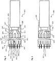
- FIG. 2 shows a plug-and-socket arrangement in a simplified side view.
- the arrangement shown comprises a socket 601 and a plug 605 of a data cable 603.
- the data cable 603 comprises four wires 607, 609, 611, 613.
- the two wires 607, 611 form a first wire pair.
- the wires 609, 613 form a second pair of wires.
- the first pair of wires may form a first channel, the second pair of wires may form a second channel for transmitting respectively first and second differential data signals.
- the plug 605 includes five electrical contact pins 615, 617, 619, 621, 623.
- the wire 607 is connected to the electrical contact pin 615.
- the wire 609 is connected to the electrical contact pin 617.
- the wire 611 is connected to the electrical contact pin 621.
- the wire 613 is connected to the electrical contact pin 623. So that means, that no core is connected to the fifth contact pin 619.
- the data cable 603 is a shielded data cable, so that the data cable 603 comprises a shield 625 in this respect, which is electrically connected via an electrical connection 627 with an outer housing 629 of the plug 605. That is, when the outer case 629 is grounded, the shield 625 is grounded.
- the four wires 607, 609, 611, 613 are also connected to the shield 625, they extend within the shield 625, so are not electrically connected to it.
- the bushing 601 includes five contact cups 631, 633, 635, 637, 639 that are configured to receive the five contact pins 615, 617, 619, 621, 623.
- Each of the five contact cups 631, 633, 635, 637, 639 comprises an electrical contact 641.
- the electrical contact pins 615, 617, 619, 621, 623 contact the contacts 641 when inserted.
- the contacts 641 of the two contact cups 637, 639 are analogous to those in FIG FIG. 1 shown arrangement with an actuator supply respectively connected to a physical interface via corresponding line sections. This is not shown here for clarity.
- the contacts 641 of the two contact cups 631, 633 are also analogous to those in FIG. 1 shown arrangement with a sensor / control supply and the physical interface connected via corresponding line sections. Again, this is not shown for the sake of clarity.
- the arrangement of the contact flaps and the electrical contact pins is such that in the inserted state, the electrical contact pins 615, 617 are accommodated in the contact flaps 631, 633.
- the electrical contact pins 621, 623 are received in the contact goblets 637, 639.
- the contact pin 619 is received in the contact cup 635.
- the contact cup 635 comprises an elastic contact cup portion 643, which is deflected by the insertion of the contact pin 619 from its rest position. This deflection is related to the paper level of the FIG. 2 up.
- a switching contact 645 is provided, which is contacted via an electrical contact 647. If, due to the insertion of the contact pin 619 into the contact cup 635, the contact cup section 643 moves upward in the direction of the switching contact 645, then the contact cup section 643 will contact it. Since the contact cup portion 643 is electrically conductive and is in electrical connection with the contact 641, an electric current flows when an electric voltage is applied to the contacts 647, 641, which is so provided according to an embodiment. This electrical current can be measured and is an indication that the data cable 603 comprises a fifth pin. In this respect, the switching devices of the input / output module can be closed. This is analogous to those associated with the FIG. 1 made statements.
- the switching contact 645 is not actuated by means of the contact cup portion 643. In this case, no electric current flows when a voltage is applied. This is a sign that the switching devices must remain open and must not be closed.
- FIG. 3 shows another plug-socket arrangement.
- FIG. 3 The arrangement shown is essentially analogous to that in FIG. 2 constructed arrangement constructed. Accordingly, reference is made to the relevant remarks. As a difference, no switching contact 645 comprising an electrical contact 647 is provided. In particular, the contact cup 635 does not include an elastic electrically conductive contact cup portion 643. Rather, in FIG. 3 provided that the plug 605 of in FIG. 3 The arrangement shown comprises an electrical resistance 701, which connects the electrical contact pin 619 with the outer housing 629, ie thus with the shield 625.
- the current waveform that is measured depends, in particular, on the type or type of electrical component used that connects the ground or shield of the data cable 603 to the fifth electrical contact pin 619. For example, if a capacitor is provided in place of the electrical resistor 701, another current waveform would be measured. For example, if a coil is provided instead of the resistor 701, then another electrical current waveform would be measured. Thus, it can therefore be determined based on a measured current profile, which electrical component it is. In particular, properties of the electrical components used can be determined via the measured current profile. Such properties are, for example, an inductance value at an inductance, a capacitance value at a capacitor, or a resistance value at a resistor.
- different electrical properties of the electrical components used encode a data cable length.
- these properties may encode operating parameters of the input / output module.
- plugs can thus be detected in an advantageous manner, which data cable is plugged, so that it can be decided whether a supply voltage should be forwarded to the remote participants or not.
- FIG. 4 shows a different plug-and-socket arrangement in a simplified sectional view.
- FIG. 4 shows a socket 801 comprising four contact cups 807.
- the socket 801 is placed with its housing to ground 805, generally to an electrical reference contact.
- the electrical contacts of the contact cups 807 are not shown for clarity.
- a plug 803 which is complementary to the socket 801 thus comprises four electrical contact pins 809.
- FIG. 5 shows the in FIG. 3 shown socket-connector assembly in a simplified another view from the front.
- the particular arrangement of the contact flaps and the contact pins to one another is such that the contact flaps the contact pins be able to record.
- the arrangement of the contact calyxes such that these contact pins 809 of the plug 803 of FIG. 4 be able to record.
- the plug 803 of the FIG. 4 into the socket 601 of FIG. 5 fits.
- no electrical current will be measured when a corresponding measurement voltage is applied.
- the plug plugged into the socket 601 is a plug with four pins and not a plug with five pins. This is then a sign that the supply voltage must not be made available to the remote subscriber connected to the data cable.
- the plug 605 according to the in FIG. 5 shown arrangement can not be in the socket 801 according to FIG. 5 due to the fifth contact pin 619 FIG. 4 be plugged.
- the new plug So far as a plug comprising five pins is called the new plug and insofar the socket comprising five contact flaps is referred to as the new socket and insofar as a plug comprising only four pins is called the old plug and insofar as a socket comprising only four contact flaps as the old socket is called, the old plug fits into the new socket.
- the new plug does not fit in the old socket, but only in the new socket.
- the measuring method that is used to decide whether or not the supply voltage should be made available to the remote subscriber is in particular to be matched to the electrical component which connects the fifth contact pin to the shield.
- an electrical resistance it is provided in particular that a corresponding measurement voltage applied and the resulting current is measured.
- the current is measured in one embodiment by means of a single transistor, which turns on at an existing electrical resistance and thus amplifies the measured current to a switching signal for the switching devices.
- different values for the electrical resistance that is to say resistance values
- ADC analog-to-digital converter
- the following two measuring methods can be used, for example.
- a DC voltage is applied and the dynamic current flow at the switch-on torque is measured or monitored via the ADC so that the electrical component can be identified as an inductance L or as a capacitance C via the current profile.
- L or C can also be determined, so that further information can also be encoded here.
- a defined alternating voltage is applied and the dynamic current profile through the electrical component is measured.
- R, L and C can be identified.
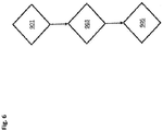
- FIG. 6 shows a flowchart of a method for operating an input / output module.
- the input / output module is, for example, the input / output module 3 according to FIG. 1 ,
- Ethernet In automation technology, various fieldbus protocols have established themselves on Ethernet with a data rate of 100 Mbit / s. Since Ethernet has meanwhile gained acceptance in the consumer sector with a data rate of 1 Gbit / s, it makes sense to also transmit fieldbus protocols with a data rate of 1 Gbit / s or 10 Gbit / s.
- a Gigabit Physics Standard Ethernet Attachment (1000-BASE-T) shows schematically in a simplified view the block diagram according to FIG. 7 ,
- the interface comprises a physical interface (also called PHY) 1001 and a transmitter and receiver unit 1003.
- PHY physical interface
- RJ45 plug 1005 is used, for example.
- the so-called "Reduced Gigabit Media Independent Interface (RGMII)" is usually used as the interface between the physical interface 1001 and the transmitter and receiver unit 1003. This interface is simply referred to as RGMII in the following.
- the RGMII transmits four bits in parallel at 250 Mbps.
- the interface between the physical interface 1001 and a transformer 1007, which is connected between the RJ45 plug 1005 and the physical interface 1001, or the interface on the cable is a signal in which, according to the PAM-5 method (PAM: Pulse amplitude modulation) via four pairs each five voltage levels with 125 Mbps are transmitted.
- PAM-5 method PAM: Pulse amplitude modulation
- the bifilar wires are used bidirectionally, with the receiver subtracting its transmit signal to receive the receive signal.
- the largest part of the cycle time is created by the physical interface 1001, which converts the four bits of the RGMII interface into the symbols of the PAM-5 method.
- the PAM-5 method is thus used to transmit signals or data between the RJ45 plug 1005 and the transformer 1007 or between the transformer 1007 and the PHY 1001, respectively.
- a physical connection comprises a switch by means of which the physical interface can be bridged. This advantageously allows the same physical interface to be used for both standard Gbit physics and for a simpler shorter-range transmission technique.
- Such a second physical connection is realized in order to connect participants who have the same voltage potential, via a simple contact or plug connection with as few contacts.
- the signals are transmitted bitwise only via two connections per direction. Only transmitters and receivers are required for this, which reduces hardware costs on the one hand and lead time on the other hand.
- the switchable physical interface is, for example, according to the in the FIG. 8 realized block diagram realized.
- a switch 1101 is provided, which is designed for example as a high-frequency switch. Furthermore, a line is formed by this switch 1101, which connects the switch 1101 to the transmitter and receiver unit 1003.
- the switch 1101 has two switching states. In the first switching state, the switch 1101 connects the transformer 1007 to the physical interface 1001. In the second switching state, the switch 1101 connects the transformer 1007 directly to the transmitter and receiver unit 1003. That is to say that in the in FIG. 8 a switch 1101 is integrated, with which the lines to the transformer 1007 either to the physical interface 1001 or directly to the transmitter and receiver unit 1003 can be switched. By means of the switch 1101 can thus be bridged advantageously the PHY 1001.
- a data transmission method between the switch 1101 and the transmitter and receiver unit 1003 may be performed by, for example, the "Special Transfer Method (STM)".
- STM Specific Transfer Method
- the user 1201 sends a first telegram 1205 to the subscriber 1203.
- the telegram 1205 may be, for example, a SimplePhysicReq telegram.
- the subscriber 1201 stores the transmission time t1_1 of the telegram 1205.
- the subscriber 1203 If the subscriber 1203 receives the telegram 1205, the subscriber 1203 stores the reception time t2_1 of the telegram 1205. The subscriber 1203 sends another telegram 1207 at the time t3_1, which is configured, for example, as a SimplePhysicRes telegram, back to the subscriber 1201. This telegram 1207 includes times t2_1 and t3_1.
- the subscriber 1201 receives the telegram 1207 and stores the reception time t4_1 of the telegram 1207.
- the subscriber 1203 transmits a telegram 1205, for example a SimplePhysicReq telegram, to the subscriber 1201 in analogy to a time t1_2 and stores the transmission time t1_2 of the telegram 1205. If the subscriber 1201 receives the telegram 1205, the subscriber 1201 stores the reception time t2_2 of the telegram 1205. The subscriber 1201 sends at time t3_2 another telegram 1207, which is formed for example as a SimplePhysicRes telegram, back to the subscriber 1203. This telegram 1207 includes the times t2_2 and t3_2. The subscriber 1203 receives the telegram 1207 and stores the reception time t4_2 of the telegram 1207.
- a telegram 1205 for example a SimplePhysicReq telegram
- Both subscribers 1201, 1203 now each have four times t1_1 to t4_1 and t1_2 to t4_2, respectively.
- Both subscribers 1201, 1203 determine or calculate a distance between themselves and the other subscriber based on their respective determined travel time.
- subscribers 1201, 1203 communicate therewith. Both subscribers 1201, 1203 switch to the simple transmission method. For both participants 1201, 1203 comprise a switchable connection according to the block diagram of FIG. 8 , If the distance is above one of the allowable distance for the easy transfer, it will not switch.
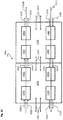
- FIG. 10 shows a block diagram of a GBus 1301.
- the GBus is a pluggable physical connection with two subscribers, which can be designed as input / output module, for example, with six lines, for example six wires, of which one transmission pair (pair of wires) per transmission line and a third pair of lines (third pair) for a voltage transmission is used.
- the GBus 1301 according to the block diagram of FIG. 10 is structured as follows:
- Two subscribers 1201, 1203 are connected to each other via two wire pairs comprising two wires 1315 and two wires 1313, respectively.
- a third pair of wires comprising two wires 1307 is represented symbolically by means of double arrows and likewise connects the two users 1201, 1203 and is used for a voltage supply.
- a first transmission direction from the subscriber 1201 to the subscriber 1203 is shown symbolically by an arrow with the reference symbol 1309.
- the transmission direction 1311 opposite from this transmission direction 1309 from the subscriber 1203 to the subscriber 1201 is shown symbolically by an arrow with the corresponding reference numeral 1311.
- the wires for a data transmission according to the transmission direction 1309 are symbolic with arrows with the reference numerals 1313 shown.
- Cores of the wire pair for data transmission according to the transmission direction 1311 are symbolically represented by arrows with the reference numeral 1315.
- subscribers 1201, 1203 For each direction of transmission 1309, 1311, subscribers 1201, 1203 include transmitter 1305 and receiver 1303. Signal transmission is done bitwise according to the SerDes method (SerDes: serializer / deserializer), where 8 bits are transmitted as 10 bits encoded at 1.25 GHz.
- SerDes serializer / deserializer
- FIG. 11 shows by way of example a block diagram of a GBus converter 1401.
- a converter 1401 is according to FIG. 11 provided that implements either a switchable physical connection or the standard GBit connection on GBus.
- converter 1401 includes two standard GBit and one GBus connection.
- FIG. 12 a switchable GBus converter 1501 is shown, the two switches 1101 analogous to FIG. 8 includes to bridge the physical interface 1001.
- Arrows shown symbolically symbolize a data transmission direction respectively a voltage transmission direction (in the double arrows 1307).
- a switchable connection (formed by the switch 1101) which can switch between a faster physical transmission at a lower range and a standard Ethernet GBit (10 Gbit / s or more) according to the connected subscribers.
- the switch 1101 described in connection with the above embodiments is the input / output module 3 of FIG Fig. 1 provided there according to the block diagrams of Fig. 8 and 12 to bridge the physical interface 391.
Landscapes
- Engineering & Computer Science (AREA)
- Theoretical Computer Science (AREA)
- Physics & Mathematics (AREA)
- General Engineering & Computer Science (AREA)
- General Physics & Mathematics (AREA)
- Computer Networks & Wireless Communication (AREA)
- Signal Processing (AREA)
- Computer Hardware Design (AREA)
- Mathematical Physics (AREA)
- Computing Systems (AREA)
- Details Of Connecting Devices For Male And Female Coupling (AREA)
- Testing Of Short-Circuits, Discontinuities, Leakage, Or Incorrect Line Connections (AREA)
Claims (15)
- Module d'entrée/sortie (3) pour un système de bus (1), comprenant :- une première source de tension continue (34) et une deuxième source de tension continue (35),- une interface physique (391), un premier transmetteur (392), un deuxième transmetteur (393), un premier sous-ensemble inductif (385), un deuxième sous-ensemble inductif (385), un premier sous-ensemble capacitif (386), un deuxième sous-ensemble capacitif (386), un premier dispositif de commutation (507) et un deuxième dispositif de commutation (509),- une prise (37) qui possède cinq flûtes à contact,- les cinq flûtes à contact comportant respectivement un contact électrique (641),- la première source de tension continue (34) pouvant être reliée électriquement à un contact électrique (641) parmi deux des cinq flûtes à contact par le biais du premier sous-ensemble inductif (385) au moyen du premier dispositif de commutation (507),- la deuxième source de tension continue (35) pouvant être reliée électriquement à un contact électrique (641) parmi deux autres des cinq flûtes à contact par le biais du deuxième sous-ensemble inductif (385) au moyen du deuxième dispositif de commutation (509),- l'interface physique (391) étant reliée électriquement aux contacts électriques (641) respectifs de deux des cinq flûtes à contact par le biais du premier transmetteur (392) et par le biais du premier sous-ensemble capacitif (386) afin d'appliquer un premier signal de données différentiel aux deux contacts électriques (641) des deux parmi les cinq flûtes à contact,- l'interface physique (391) étant reliée électriquement aux contacts électriques (641) respectifs des deux autres des cinq flûtes à contact par le biais du deuxième transmetteur (393) et par le biais du deuxième sous-ensemble capacitif (386) afin d'appliquer un deuxième signal de données différentiel aux deux contacts électriques (641) des deux autres des cinq flûtes à contact, et- un dispositif de mesure (205) destiné à détecter une fiche (605) d'un câble de données (4) à quatre conducteurs, lequel est configuré pour détecter, en présence d'une fiche (605) insérée dans la prise (37), si la fiche (605) comporte quatre ou cinq broches de contact électriques qui sont respectivement insérées dans l'une des flûtes à contact et qui sont reliées électriquement avec le contact électrique (641) respectif des flûtes à contact,- le dispositif de mesure (205) étant configuré pour fermer le premier et le deuxième dispositif de commutation (507, 509) exclusivement dans le cas d'une détection de cinq broches de contact électriques en vue d'appliquer, par le biais des contacts électriques (641) respectifs des flûtes à contact, une tension d'alimentation respective des deux sources de tension continue (34, 35) aux broches de contact insérées correspondantes de la fiche (605) insérée dans la prise (37).
- Module d'entrée/sortie (3) selon la revendication 1, le dispositif de mesure (205) étant configuré pour appliquer une tension de mesure électrique entre le contact électrique (641) de la cinquième flûte à contact, laquelle est différente des deux et des deux autres parmi les cinq flûtes à contact, et un contact de référence (513) électrique et pour mesurer un courant électrique qui circule entre le contact de référence (513) et le contact électrique (641) de la cinquième flûte à contact, le contact de référence électrique (513) étant isolé du contact électrique (641) de la cinquième flûte à contact, le dispositif de mesure (205) étant configuré pour fermer les deux dispositifs de commutation (507, 509) lorsqu'un courant électrique circulant entre le contact de référence (513) électrique et le contact électrique (641) de la cinquième flûte à contact est mesuré alors que la tension de mesure électrique est appliquée.
- Module d'entrée/sortie (3) selon la revendication 2, le dispositif de mesure (205) comprenant un transistor qui est configuré pour commuter à l'état passant en présence d'un courant électrique qui circule entre le contact de référence (513) électrique et le contact électrique (641) de la cinquième flûte à contact, le dispositif de mesure (205) étant configuré pour détecter une commutation à l'état passant du transistor et pour fermer les deux dispositifs de commutation (507, 509) en cas de détection d'une commutation à l'état passant du transistor.
- Module d'entrée/sortie (3) selon la revendication 2 ou 3, le dispositif de mesure (205) étant configuré pour déterminer, en se basant sur la tension de mesure appliquée et sur le courant électrique mesuré, le type de composant électrique (525) intégré dans la fiche (605) qui a établi une liaison électrique entre le contact de référence (513) électrique et le contact électrique (641) de la cinquième flûte de contact, le dispositif de mesure (205) étant notamment configuré pour déterminer une propriété électrique du composant électrique (525), le composant électrique étant notamment le câble de données (4) attaché.
- Module d'entrée/sortie (3) selon l'une des revendications précédentes, le dispositif de mesure (205) comprenant un contact de commutation électrique (645) et le contact électrique (641) de la cinquième flûte de contact, laquelle est différente des deux et des deux autres parmi les cinq flûtes à contact, est monté mobile, de sorte que lors d'une insertion d'une broche de contact électrique de la fiche (605) dans la cinquième flûte de contact, la broche de contact électrique insérée dans la cinquième flûte de contact déplace le contact électrique (643) monté mobile, de sorte que celui-ci actionne le contact de commutation électrique (645), le dispositif de mesure (205) étant configuré pour fermer les deux dispositifs de commutation (507, 509) lorsque le contact de commutation électrique (645) est actionné.
- Module d'entrée/sortie (3) selon l'une des revendications précédentes, le dispositif de mesure (205) étant configuré pour contrôler par le biais du contact électrique (641) de la cinquième flûte de contact, laquelle est différente des deux et des deux autres parmi les cinq flûtes à contact, si une mémoire programmable est intégrée dans la fiche (605) en tant que composant électrique (525) et pour fermer les deux dispositifs de commutation (507, 509) en se basant sur le contrôle.
- Procédé pour faire fonctionner un module d'entrée/sortie (3) selon l'une des revendications précédentes, comprenant les étapes suivantes :- détection (901), au moyen du dispositif de mesure (205) en présence d'une fiche (605) insérée dans la prise (37), si la fiche (605) comporte quatre ou cinq broches de contact électriques, lesquelles sont respectivement insérées dans l'une des flûtes à contact et sont reliées électriquement au contact électrique (641) respectif des flûtes à contact,- fermeture (903) des deux dispositifs de commutation (507, 509) au moyen du dispositif de mesure (205) exclusivement dans le cas d'une détection de cinq broches de contact électriques de sorte que, du fait des dispositifs de commutation (507, 509) fermés, une tension d'alimentation respective des deux sources de tension continue (34, 35) est appliquée (905) par le biais des contacts électriques (641) respectifs des flûtes à contact aux broches de contact insérées correspondantes de la fiche (605) insérée dans la prise (37).
- Procédé selon la revendication 7 en référence au module d'entrée/sortie (3) rapporté à la revendication 2, comprenant en outré :- application, au moyen du dispositif de mesure (205), d'une tension de mesure électrique entre le contact électrique (641) de la cinquième flûte de contact, laquelle est différente des deux et des deux autres parmi les cinq flûtes à contact, et un contact de référence (513) électrique et- mesure, au moyen du dispositif de mesure (205), déterminant si un courant électrique circule entre le contact de référence (513) et le contact électrique (641) de la cinquième flûte de contact,- fermeture, au moyen du dispositif de mesure (205), des deux dispositifs de commutation (507, 509) lorsqu'un courant électrique circulant entre le contact de référence (513) électrique et le contact électrique (641) de la cinquième flûte à contact est mesuré alors que la tension de mesure électrique est appliquée.
- Procédé selon la revendication 7 ou 8 en référence au module d'entrée/sortie (3) rapporté à la revendication 3, comprenant en outré :- fermeture, au moyen du dispositif de mesure (205), des deux dispositifs de commutation (507, 509) lorsque le dispositif de mesure (205) détecte une commutation à l'état passant du transistor.
- Procédé selon l'une des revendications 7 à 9 en référence au module d'entrée/sortie (3) rapporté à la revendication 4, comprenant en outré :détermination, au moyen du dispositif de mesure (205) et en se basant sur la tension de mesure appliquée et sur le courant électrique mesuré, du type de composant électrique (525) intégré dans la fiche (605) qui a établi une liaison électrique entre le contact de référence (513) électrique et le contact électrique (641) de la cinquième flûte de contact, une propriété électrique du composant électrique (525) étant notamment déterminée, le composant électrique (525) étant notamment le câble de données (4) attaché.
- Procédé selon l'une des revendications 7 à 10 en référence au module d'entrée/sortie (3) rapporté à la revendication 5, comprenant en outré :- fermeture des deux dispositifs de commutation (507, 509) au moyen du dispositif de mesure (205) lorsque le contact de commutation électrique (645) est actionné.
- Procédé selon l'une des revendications 7 à 11 en référence au module d'entrée/sortie (3) rapporté à la revendication 6, comprenant en outre :- contrôle, au moyen du dispositif de mesure (205) et par le biais du contact électrique (641) de la cinquième flûte de contact, laquelle est différente des deux et des deux autres parmi les cinq flûtes à contact, déterminant si une mémoire programmable est intégrée dans la fiche (605) en tant que composant électrique (525)- fermeture des deux dispositifs de commutation (507, 509) au moyen du dispositif de mesure (205) en se basant sur le contrôle.
- Câble de données (4) pour un module d'entrée/sortie (3) pour un système de bus (1) selon l'une des revendications 1 à 6, comprenant :deux paires de fils, une fiche (605) comportant cinq broches de contact électriques et un blindage, quatre des cinq broches de contact électriques étant reliées électriquement respectivement à l'un des fils des deux paires de fils, au moins un composant électrique (525) étant branché entre la cinquième broche de contact et le blindage, l'au moins un composant électrique (525) étant choisi dans le groupe de composants électriques (525) suivant : résistance, inductance, condensateur, diode, mémoire programmable, etles propriétés électriques du composant électrique codant une longueur du câble de données et/ou des paramètres de fonctionnement du module d'entrée/sortie, une propriété du câble de données (4) étant notamment enregistrée dans la mémoire programmable.
- Système de bus (1), comprenant un module d'entrée/sortie (3) selon l'une des revendications 1 à 8 et un câble de données (4) selon la revendication 13.
- Programme informatique, comprenant un code de programme destiné à mettre en oeuvre le procédé selon l'une des revendications 7 à 12 lorsque le programme informatique est exécuté sur un ordinateur, notamment sur le module d'entrée/sortie (3) selon l'une des revendications 1 à 6.
Applications Claiming Priority (2)
| Application Number | Priority Date | Filing Date | Title |
|---|---|---|---|
| DE102015116800.6A DE102015116800B3 (de) | 2015-10-02 | 2015-10-02 | Eingabe-/Ausgabemodul für ein Bussystem |
| PCT/EP2016/073123 WO2017055355A1 (fr) | 2015-10-02 | 2016-09-28 | Bus d'entrée/sortie pour un système de bus |
Publications (2)
| Publication Number | Publication Date |
|---|---|
| EP3195525A1 EP3195525A1 (fr) | 2017-07-26 |
| EP3195525B1 true EP3195525B1 (fr) | 2018-01-17 |
Family
ID=57018139
Family Applications (1)
| Application Number | Title | Priority Date | Filing Date |
|---|---|---|---|
| EP16774486.1A Active EP3195525B1 (fr) | 2015-10-02 | 2016-09-28 | Bus d'entrée/sortie pour un système de bus |
Country Status (5)
| Country | Link |
|---|---|
| US (1) | US10614013B2 (fr) |
| EP (1) | EP3195525B1 (fr) |
| CN (1) | CN107113181B (fr) |
| DE (1) | DE102015116800B3 (fr) |
| WO (1) | WO2017055355A1 (fr) |
Families Citing this family (15)
| Publication number | Priority date | Publication date | Assignee | Title |
|---|---|---|---|---|
| US11797469B2 (en) | 2013-05-07 | 2023-10-24 | Snap-On Incorporated | Method and system of using USB user interface in electronic torque wrench |
| US10231254B2 (en) * | 2016-08-05 | 2019-03-12 | Nokia Technologies Oy | 5G cloud RAN method for symbol by symbol bit streaming |
| US10080215B2 (en) * | 2016-08-05 | 2018-09-18 | Nokia Technologies Oy | Transportation of user plane data across a split fronthaul interface |
| US10630293B2 (en) * | 2017-03-31 | 2020-04-21 | Adanced Micro Devices, Inc. | High speed transmitter |
| DE102017219001B3 (de) * | 2017-10-24 | 2019-03-07 | Festo Ag & Co. Kg | Kommunikationsteilnehmer und Kommunikationssystem |
| DE102017127983A1 (de) * | 2017-11-27 | 2019-05-29 | Beckhoff Automation Gmbh | Sicherungsmodul und feldbussystem mit sicherungsmodul |
| US10867504B2 (en) * | 2019-04-25 | 2020-12-15 | Baker Hughes Oilfield Operations Llc | Monitoring of marshalling cabinet wiring |
| CN110176699B (zh) * | 2019-06-24 | 2024-02-13 | 中国电子科技集团公司第三十四研究所 | 一种单芯电缆恒流供电系统的海底分支器及使用方法 |
| DE102020121752A1 (de) * | 2020-08-19 | 2022-02-24 | Turck Holding Gmbh | Elektrischer Steckverbinder |
| CN112685340B (zh) * | 2020-12-28 | 2024-07-19 | 深圳市合信自动化技术有限公司 | 一种自动启动EtherCat冗余功能的方法及装置 |
| CN115548790A (zh) * | 2021-06-30 | 2022-12-30 | 施耐德电气工业公司 | 连接器、安装定向检测方法和显示系统 |
| DE102021121996A1 (de) * | 2021-08-25 | 2023-03-02 | Zf Cv Systems Global Gmbh | Vorrichtung zur Überprüfung der Funktion einer Kabelabschirmung einer drahtgebundenen Kommunikationsverbindung zwischen zwei Kommunikationspartnern, elektronische Verarbeitungseinheit und Fahrzeug |
| DE102023000951A1 (de) | 2022-04-11 | 2023-10-12 | Sew-Eurodrive Gmbh & Co Kg | Bussystem und Verfahren zum Betrieb eines Bussystems |
| DE102023001538A1 (de) | 2022-05-02 | 2023-11-02 | Sew-Eurodrive Gmbh & Co Kg | Bussystem für ein Antriebssystem |
| DE102023123139A1 (de) | 2023-08-29 | 2025-03-06 | Turck Holding Gmbh | Device zum Betreiben in einem Netzwerk, Automatisierungssystem und Verfahren zum Betrieb des Automatisierungssystems |
Family Cites Families (12)
| Publication number | Priority date | Publication date | Assignee | Title |
|---|---|---|---|---|
| US6218930B1 (en) | 1999-03-10 | 2001-04-17 | Merlot Communications | Apparatus and method for remotely powering access equipment over a 10/100 switched ethernet network |
| DE10163393B4 (de) * | 2001-12-21 | 2013-01-10 | Werner Turck Gmbh & Co. Kg | Anschlusselement für einen Bus |
| DE102006011715B4 (de) * | 2006-03-14 | 2010-08-12 | Moeller Gmbh | Vorrichtung und Verfahren zur Messung einer ersten Spannung und einer zweiten Spannung mit einem Differenzspannungsmesser |
| JP4961999B2 (ja) * | 2006-12-25 | 2012-06-27 | 株式会社ニコン | 電子機器 |
| EP2210182A1 (fr) * | 2007-11-15 | 2010-07-28 | Nokia Corporation | Connexion d'alimentation entre des interfaces séries |
| US7855573B1 (en) * | 2009-12-14 | 2010-12-21 | Caterpillar Trimble Control Technologies Llc | Controller area network active bus terminator |
| CN103201800B (zh) * | 2010-09-30 | 2016-02-03 | 加布里埃尔专利技术有限责任公司 | 减少由传输导线和电缆中的电介质材料导致的信号失真的方法 |
| US8779786B2 (en) | 2011-10-18 | 2014-07-15 | Broadcom Corporation | Remote sensing of PD-side voltage in 4-pair PoE applications for estimating cable resistance |
| DE102011087828A1 (de) * | 2011-12-06 | 2013-06-06 | Continental Automotive Gmbh | Netzwerk-Komponente für ein Fahrzeug-Netzwerk und entsprechendes Fahrzeug-Netzwerk |
| US9537644B2 (en) * | 2012-02-23 | 2017-01-03 | Lattice Semiconductor Corporation | Transmitting multiple differential signals over a reduced number of physical channels |
| DE102013201106B4 (de) * | 2013-01-24 | 2014-12-11 | Smiths Heimann Gmbh | Busknoten und Bussystem sowie Verfahren zur Identifikation der Busknoten des Bussystems |
| JP6363189B2 (ja) * | 2013-07-18 | 2018-07-25 | フィリップス ライティング ホールディング ビー ヴィ | Dc電力分配システム |
-
2015
- 2015-10-02 DE DE102015116800.6A patent/DE102015116800B3/de not_active Withdrawn - After Issue
-
2016
- 2016-09-28 EP EP16774486.1A patent/EP3195525B1/fr active Active
- 2016-09-28 CN CN201680003433.XA patent/CN107113181B/zh active Active
- 2016-09-28 WO PCT/EP2016/073123 patent/WO2017055355A1/fr not_active Ceased
-
2017
- 2017-03-15 US US15/459,804 patent/US10614013B2/en active Active
Also Published As
| Publication number | Publication date |
|---|---|
| DE102015116800B3 (de) | 2016-12-29 |
| CN107113181A (zh) | 2017-08-29 |
| US20170185556A1 (en) | 2017-06-29 |
| US10614013B2 (en) | 2020-04-07 |
| EP3195525A1 (fr) | 2017-07-26 |
| CN107113181B (zh) | 2020-07-17 |
| WO2017055355A1 (fr) | 2017-04-06 |
Similar Documents
| Publication | Publication Date | Title |
|---|---|---|
| EP3195525B1 (fr) | Bus d'entrée/sortie pour un système de bus | |
| EP3338404B1 (fr) | Système de bus | |
| EP2000866B1 (fr) | Dispositif de surveillance destiné à la reconnaissance d'un adressage incorrect d'un esclave dans un système de bus de terrain | |
| EP3284210B1 (fr) | Système de bus comportant un module d'alimentation et un module de consommateur | |
| WO2019122208A1 (fr) | Station d'abonné pour un système de bus série et procédé pour envoyer un message dans un système de bus série | |
| WO2019174957A1 (fr) | Dispositif d'émission/réception pour un système de bus et procédé de réduction d'émissions filaires | |
| EP3766213B1 (fr) | Dispositif d'émission/réception pour un système de bus et procédé de réduction d'émissions filaires | |
| DE102016112362A1 (de) | Konzept zur Reichweitenverlängerung für eine kombinierte Daten- und Energieleitung | |
| DE102016109450A1 (de) | Konzept einer Absicherung einer Versorgungsspannung | |
| EP3744049A1 (fr) | Station d'abonné pour un système de bus en série et procédé pour l'envoi d'un message dans un système de bus en série | |
| DE102019200907A1 (de) | Teilnehmerstation für ein Bussystem und Verfahren zur Datenübertragung in einem Bussystem | |
| DE102005059012B4 (de) | ASI-Sytem zum Anschluß mehrerer Sensoren und/oder Aktuatoren an eine Steuerung | |
| DE102021207666A1 (de) | Sende-/Empfangseinrichtung und Verfahren für die Erkennung von Bussystem-Manipulation in einem seriellen Bussystem | |
| EP2348374B1 (fr) | Procédé de détection d'un adressage multiple défectueux d'un réseau fonctionnant selon le principe maître-esclave et un réseau à interface de capteur d'actionneur correspondant | |
| WO2019122212A1 (fr) | Station de participant au bus pour un système de bus série et procédé d'envoi d'un message dans un système de bus série | |
| WO2019122209A1 (fr) | Station d'abonné pour un système de bus en série et procédé d'émission d'un message dans un système de bus en série | |
| EP3744050A1 (fr) | Station de participant au bus pour un système de bus série et procédé d'envoi d'un message dans un système de bus série | |
| EP1334589B1 (fr) | Transmission de donnees | |
| DE102012202423A1 (de) | Erdschlusswächter für ein ASi-Sensor-Aktor-Netzwerk | |
| DE102016224959A1 (de) | Vorrichtung für ein Bussystem und Verfahren zur Dämpfung von Reflexionen bei einer Datenübertragung in einem Bussystem | |
| DE102007013379B4 (de) | Netzwerkabschluß zum Anschluß an eine Busleitung | |
| DE102024203863A1 (de) | Sende-/Empfangseinrichtung für eine Teilnehmerstation eines seriellen Bussystems und Verfahren zur Kommunikation mit differentiellen Signalen in einem seriellen Bussystem | |
| WO2025223737A1 (fr) | Dispositif émetteur-récepteur pour une station d'abonné d'un système de bus série et procédé de communication utilisant des signaux différentiels dans un système de bus série | |
| EP2683124A1 (fr) | Dispositif d'émission/réception et utilisation dans un système d'automatisation | |
| WO2025201678A1 (fr) | Procédé et systeme de transmission électrique de symboles |
Legal Events
| Date | Code | Title | Description |
|---|---|---|---|
| PUAI | Public reference made under article 153(3) epc to a published international application that has entered the european phase |
Free format text: ORIGINAL CODE: 0009012 |
|
| 17P | Request for examination filed |
Effective date: 20170418 |
|
| AK | Designated contracting states |
Kind code of ref document: A1 Designated state(s): AL AT BE BG CH CY CZ DE DK EE ES FI FR GB GR HR HU IE IS IT LI LT LU LV MC MK MT NL NO PL PT RO RS SE SI SK SM TR |
|
| AX | Request for extension of the european patent |
Extension state: BA ME |
|
| GRAP | Despatch of communication of intention to grant a patent |
Free format text: ORIGINAL CODE: EPIDOSNIGR1 |
|
| RIC1 | Information provided on ipc code assigned before grant |
Ipc: H04L 12/10 20060101AFI20170725BHEP Ipc: G06F 13/42 20060101ALI20170725BHEP Ipc: G06F 13/40 20060101ALI20170725BHEP Ipc: H01R 13/658 20110101ALI20170725BHEP Ipc: H04L 12/40 20060101ALI20170725BHEP Ipc: H01R 13/66 20060101ALI20170725BHEP Ipc: G01R 31/04 20060101ALI20170725BHEP Ipc: H01R 13/641 20060101ALI20170725BHEP Ipc: H01R 33/74 20060101ALI20170725BHEP |
|
| DAV | Request for validation of the european patent (deleted) | ||
| DAX | Request for extension of the european patent (deleted) | ||
| INTG | Intention to grant announced |
Effective date: 20170817 |
|
| GRAS | Grant fee paid |
Free format text: ORIGINAL CODE: EPIDOSNIGR3 |
|
| GRAA | (expected) grant |
Free format text: ORIGINAL CODE: 0009210 |
|
| AK | Designated contracting states |
Kind code of ref document: B1 Designated state(s): AL AT BE BG CH CY CZ DE DK EE ES FI FR GB GR HR HU IE IS IT LI LT LU LV MC MK MT NL NO PL PT RO RS SE SI SK SM TR |
|
| REG | Reference to a national code |
Ref country code: GB Ref legal event code: FG4D Free format text: NOT ENGLISH |
|
| REG | Reference to a national code |
Ref country code: CH Ref legal event code: EP |
|
| REG | Reference to a national code |
Ref country code: IE Ref legal event code: FG4D Free format text: LANGUAGE OF EP DOCUMENT: GERMAN |
|
| REG | Reference to a national code |
Ref country code: AT Ref legal event code: REF Ref document number: 965089 Country of ref document: AT Kind code of ref document: T Effective date: 20180215 |
|
| REG | Reference to a national code |
Ref country code: DE Ref legal event code: R096 Ref document number: 502016000472 Country of ref document: DE |
|
| REG | Reference to a national code |
Ref country code: NL Ref legal event code: MP Effective date: 20180117 |
|
| REG | Reference to a national code |
Ref country code: LT Ref legal event code: MG4D |
|
| PG25 | Lapsed in a contracting state [announced via postgrant information from national office to epo] |
Ref country code: NL Free format text: LAPSE BECAUSE OF FAILURE TO SUBMIT A TRANSLATION OF THE DESCRIPTION OR TO PAY THE FEE WITHIN THE PRESCRIBED TIME-LIMIT Effective date: 20180117 |
|
| PG25 | Lapsed in a contracting state [announced via postgrant information from national office to epo] |
Ref country code: NO Free format text: LAPSE BECAUSE OF FAILURE TO SUBMIT A TRANSLATION OF THE DESCRIPTION OR TO PAY THE FEE WITHIN THE PRESCRIBED TIME-LIMIT Effective date: 20180417 Ref country code: FI Free format text: LAPSE BECAUSE OF FAILURE TO SUBMIT A TRANSLATION OF THE DESCRIPTION OR TO PAY THE FEE WITHIN THE PRESCRIBED TIME-LIMIT Effective date: 20180117 Ref country code: LT Free format text: LAPSE BECAUSE OF FAILURE TO SUBMIT A TRANSLATION OF THE DESCRIPTION OR TO PAY THE FEE WITHIN THE PRESCRIBED TIME-LIMIT Effective date: 20180117 Ref country code: CY Free format text: LAPSE BECAUSE OF FAILURE TO SUBMIT A TRANSLATION OF THE DESCRIPTION OR TO PAY THE FEE WITHIN THE PRESCRIBED TIME-LIMIT Effective date: 20180117 Ref country code: HR Free format text: LAPSE BECAUSE OF FAILURE TO SUBMIT A TRANSLATION OF THE DESCRIPTION OR TO PAY THE FEE WITHIN THE PRESCRIBED TIME-LIMIT Effective date: 20180117 Ref country code: ES Free format text: LAPSE BECAUSE OF FAILURE TO SUBMIT A TRANSLATION OF THE DESCRIPTION OR TO PAY THE FEE WITHIN THE PRESCRIBED TIME-LIMIT Effective date: 20180117 |
|
| PG25 | Lapsed in a contracting state [announced via postgrant information from national office to epo] |
Ref country code: GR Free format text: LAPSE BECAUSE OF FAILURE TO SUBMIT A TRANSLATION OF THE DESCRIPTION OR TO PAY THE FEE WITHIN THE PRESCRIBED TIME-LIMIT Effective date: 20180418 Ref country code: BG Free format text: LAPSE BECAUSE OF FAILURE TO SUBMIT A TRANSLATION OF THE DESCRIPTION OR TO PAY THE FEE WITHIN THE PRESCRIBED TIME-LIMIT Effective date: 20180417 Ref country code: SE Free format text: LAPSE BECAUSE OF FAILURE TO SUBMIT A TRANSLATION OF THE DESCRIPTION OR TO PAY THE FEE WITHIN THE PRESCRIBED TIME-LIMIT Effective date: 20180117 Ref country code: IS Free format text: LAPSE BECAUSE OF FAILURE TO SUBMIT A TRANSLATION OF THE DESCRIPTION OR TO PAY THE FEE WITHIN THE PRESCRIBED TIME-LIMIT Effective date: 20180517 Ref country code: LV Free format text: LAPSE BECAUSE OF FAILURE TO SUBMIT A TRANSLATION OF THE DESCRIPTION OR TO PAY THE FEE WITHIN THE PRESCRIBED TIME-LIMIT Effective date: 20180117 Ref country code: RS Free format text: LAPSE BECAUSE OF FAILURE TO SUBMIT A TRANSLATION OF THE DESCRIPTION OR TO PAY THE FEE WITHIN THE PRESCRIBED TIME-LIMIT Effective date: 20180117 Ref country code: PL Free format text: LAPSE BECAUSE OF FAILURE TO SUBMIT A TRANSLATION OF THE DESCRIPTION OR TO PAY THE FEE WITHIN THE PRESCRIBED TIME-LIMIT Effective date: 20180117 |
|
| REG | Reference to a national code |
Ref country code: FR Ref legal event code: PLFP Year of fee payment: 3 |
|
| PG25 | Lapsed in a contracting state [announced via postgrant information from national office to epo] |
Ref country code: MT Free format text: LAPSE BECAUSE OF FAILURE TO SUBMIT A TRANSLATION OF THE DESCRIPTION OR TO PAY THE FEE WITHIN THE PRESCRIBED TIME-LIMIT Effective date: 20180117 |
|
| REG | Reference to a national code |
Ref country code: DE Ref legal event code: R097 Ref document number: 502016000472 Country of ref document: DE |
|
| PG25 | Lapsed in a contracting state [announced via postgrant information from national office to epo] |
Ref country code: AL Free format text: LAPSE BECAUSE OF FAILURE TO SUBMIT A TRANSLATION OF THE DESCRIPTION OR TO PAY THE FEE WITHIN THE PRESCRIBED TIME-LIMIT Effective date: 20180117 Ref country code: EE Free format text: LAPSE BECAUSE OF FAILURE TO SUBMIT A TRANSLATION OF THE DESCRIPTION OR TO PAY THE FEE WITHIN THE PRESCRIBED TIME-LIMIT Effective date: 20180117 |
|
| PLBE | No opposition filed within time limit |
Free format text: ORIGINAL CODE: 0009261 |
|
| STAA | Information on the status of an ep patent application or granted ep patent |
Free format text: STATUS: NO OPPOSITION FILED WITHIN TIME LIMIT |
|
| PG25 | Lapsed in a contracting state [announced via postgrant information from national office to epo] |
Ref country code: DK Free format text: LAPSE BECAUSE OF FAILURE TO SUBMIT A TRANSLATION OF THE DESCRIPTION OR TO PAY THE FEE WITHIN THE PRESCRIBED TIME-LIMIT Effective date: 20180117 Ref country code: SK Free format text: LAPSE BECAUSE OF FAILURE TO SUBMIT A TRANSLATION OF THE DESCRIPTION OR TO PAY THE FEE WITHIN THE PRESCRIBED TIME-LIMIT Effective date: 20180117 Ref country code: CZ Free format text: LAPSE BECAUSE OF FAILURE TO SUBMIT A TRANSLATION OF THE DESCRIPTION OR TO PAY THE FEE WITHIN THE PRESCRIBED TIME-LIMIT Effective date: 20180117 Ref country code: SM Free format text: LAPSE BECAUSE OF FAILURE TO SUBMIT A TRANSLATION OF THE DESCRIPTION OR TO PAY THE FEE WITHIN THE PRESCRIBED TIME-LIMIT Effective date: 20180117 |
|
| 26N | No opposition filed |
Effective date: 20181018 |
|
| PG25 | Lapsed in a contracting state [announced via postgrant information from national office to epo] |
Ref country code: MC Free format text: LAPSE BECAUSE OF FAILURE TO SUBMIT A TRANSLATION OF THE DESCRIPTION OR TO PAY THE FEE WITHIN THE PRESCRIBED TIME-LIMIT Effective date: 20180117 |
|
| REG | Reference to a national code |
Ref country code: BE Ref legal event code: MM Effective date: 20180930 |
|
| REG | Reference to a national code |
Ref country code: IE Ref legal event code: MM4A |
|
| PG25 | Lapsed in a contracting state [announced via postgrant information from national office to epo] |
Ref country code: LU Free format text: LAPSE BECAUSE OF NON-PAYMENT OF DUE FEES Effective date: 20180928 |
|
| PG25 | Lapsed in a contracting state [announced via postgrant information from national office to epo] |
Ref country code: IE Free format text: LAPSE BECAUSE OF NON-PAYMENT OF DUE FEES Effective date: 20180928 |
|
| PG25 | Lapsed in a contracting state [announced via postgrant information from national office to epo] |
Ref country code: BE Free format text: LAPSE BECAUSE OF NON-PAYMENT OF DUE FEES Effective date: 20180930 |
|
| PG25 | Lapsed in a contracting state [announced via postgrant information from national office to epo] |
Ref country code: TR Free format text: LAPSE BECAUSE OF FAILURE TO SUBMIT A TRANSLATION OF THE DESCRIPTION OR TO PAY THE FEE WITHIN THE PRESCRIBED TIME-LIMIT Effective date: 20180117 |
|
| PG25 | Lapsed in a contracting state [announced via postgrant information from national office to epo] |
Ref country code: PT Free format text: LAPSE BECAUSE OF FAILURE TO SUBMIT A TRANSLATION OF THE DESCRIPTION OR TO PAY THE FEE WITHIN THE PRESCRIBED TIME-LIMIT Effective date: 20180117 |
|
| PG25 | Lapsed in a contracting state [announced via postgrant information from national office to epo] |
Ref country code: RO Free format text: LAPSE BECAUSE OF FAILURE TO SUBMIT A TRANSLATION OF THE DESCRIPTION OR TO PAY THE FEE WITHIN THE PRESCRIBED TIME-LIMIT Effective date: 20180117 Ref country code: HU Free format text: LAPSE BECAUSE OF FAILURE TO SUBMIT A TRANSLATION OF THE DESCRIPTION OR TO PAY THE FEE WITHIN THE PRESCRIBED TIME-LIMIT; INVALID AB INITIO Effective date: 20160928 Ref country code: MK Free format text: LAPSE BECAUSE OF NON-PAYMENT OF DUE FEES Effective date: 20180117 |
|
| PG25 | Lapsed in a contracting state [announced via postgrant information from national office to epo] |
Ref country code: SI Free format text: LAPSE BECAUSE OF NON-PAYMENT OF DUE FEES Effective date: 20180928 |
|
| GBPC | Gb: european patent ceased through non-payment of renewal fee |
Effective date: 20200928 |
|
| PG25 | Lapsed in a contracting state [announced via postgrant information from national office to epo] |
Ref country code: GB Free format text: LAPSE BECAUSE OF NON-PAYMENT OF DUE FEES Effective date: 20200928 |
|
| REG | Reference to a national code |
Ref country code: CH Ref legal event code: U11 Free format text: ST27 STATUS EVENT CODE: U-0-0-U10-U11 (AS PROVIDED BY THE NATIONAL OFFICE) Effective date: 20251001 |
|
| PGFP | Annual fee paid to national office [announced via postgrant information from national office to epo] |
Ref country code: DE Payment date: 20250811 Year of fee payment: 10 |
|
| PGFP | Annual fee paid to national office [announced via postgrant information from national office to epo] |
Ref country code: FR Payment date: 20250926 Year of fee payment: 10 Ref country code: AT Payment date: 20250918 Year of fee payment: 10 |
|
| PGFP | Annual fee paid to national office [announced via postgrant information from national office to epo] |
Ref country code: IT Payment date: 20250930 Year of fee payment: 10 |
|
| PGFP | Annual fee paid to national office [announced via postgrant information from national office to epo] |
Ref country code: CH Payment date: 20251001 Year of fee payment: 10 |