EP3196172B1 - Dispositif à air refroidi pour tremper du verre. - Google Patents
Dispositif à air refroidi pour tremper du verre. Download PDFInfo
- Publication number
- EP3196172B1 EP3196172B1 EP16152099.4A EP16152099A EP3196172B1 EP 3196172 B1 EP3196172 B1 EP 3196172B1 EP 16152099 A EP16152099 A EP 16152099A EP 3196172 B1 EP3196172 B1 EP 3196172B1
- Authority
- EP
- European Patent Office
- Prior art keywords
- air
- pressure
- pressure air
- air supply
- low
- Prior art date
- Legal status (The legal status is an assumption and is not a legal conclusion. Google has not performed a legal analysis and makes no representation as to the accuracy of the status listed.)
- Active
Links
Images


Classifications
-
- C—CHEMISTRY; METALLURGY
- C03—GLASS; MINERAL OR SLAG WOOL
- C03B—MANUFACTURE, SHAPING, OR SUPPLEMENTARY PROCESSES
- C03B27/00—Tempering or quenching glass products
- C03B27/04—Tempering or quenching glass products using gas
- C03B27/0404—Nozzles, blow heads, blowing units or their arrangements, specially adapted for flat or bent glass sheets
Definitions
- the present invention relates to a cooling apparatus, particularly relates to a device utilizing air for tempered glass cooling.
- the existing devices utilizing air for tempered glass cooling mainly consists of a compressed air supply unit, an air duct and an air nozzle located on the air duct, wherein the compressed air supply unit is used for supplying high-pressure cold air to the air duct.
- the air nozzle is used for giving out cold air to the glasses that are to be processed, thereby performing tempered glass cooling.
- the air nozzles are usually circular holes. These air nozzles' performance has the disadvantage of uneven distribution of air pressure.
- the glass surface is susceptible to stress marks.
- CN2608497Y discloses a "slit-type air gate nozzle".
- This nozzle is configured as a slit type so that the air outflow is concentrated. The occurrence of uneven distribution of air pressure is avoided. The stress distribution of glasses is more uniform and reasonable.
- the following deficiencies still exist in this slit-type air gate nozzle: Since each air nozzle only includes one slit, each air nozzle can only form one wind band on glasses. Also, the wind bands are independent of each other. They cannot be connected together. If you want to link up the wind bands formed in each slit, it is necessary to configure closely arranged air nozzles, making the structure complicated.
- CN203960044U discloses a tempered glass air-cooling nozzle and an air duct comprising the same.
- a detailed piping arrangement of how air is supplied to air ducts and ejects out of the nozzles in a multiple air ducts application are not disclosed by this Chinese utility model.
- the present invention provides a device utilizing air for tempered glass cooling.
- this device utilizing air for tempered glass cooling two wind bands can be formed on each air nozzle.
- the air cooling effect is good, and the wind bands between adjacent air nozzles can be closely arranged.
- the inner cavity of the housing body is formed by an air inlet section, an air guiding section and an air outlet section connected in sequence.
- the embedded body is formed by connecting a tapered body and a separating body, wherein the tapered body matches with and fits inside the air guiding section; a space between an external wall of the tapered body and an air guiding section surface forms the tapered air guiding passage; a radial dimension of the air outlet section is bigger than the largest diameter of the air guiding section; the separating body matches with and fits on a top part of the air outlet section; the separating body forms the partition.
- the separating body matches between the separating body and the air outlet section achieves positioning function, so that the embedded body simply needs to be mounted into the inner cavity of the housing body, and then the tapered air guiding passage can be formed; also, the separating body forms the partition, thereby separating an exit of the tapered air guiding passage into the two arc-shaped air outlets, so that the separating body does not only serve a positioning function but also a separating function.
- a cross section of the air outlet section has a circular shape; outer side surfaces of the separating body are circular arc surfaces which match with the circular cross section of the air outlet section. This is advantageous to the matching and positioning between the separating body and the air outlet section.
- the tapered air guiding passage has the same cross sectional area at any of its cross sections.
- the purpose is to ensure stability of air volume and air pressure everywhere within the tapered air guiding passage, thereby ensuring that the air volume and air pressure blowing out from the arc-shaped air outlets are even.
- taper shape of the air guiding section and taper shape of the tapered body are different, wherein a width of the tapered air guiding passage at an end corresponding to a tip of the tapered body is wider. The width at another end of the tapered air guiding passage is narrower.
- a middle section between said end and said anther end of the tapered air guiding passage is a gradational transition between the wider width at said end and the narrower end at said another end.
- a taper of the air guiding section is 30-120 degrees; a taper of the tapered body is 35-150 degrees.
- a cross section of the air inlet section is in a circular shape; the tip of the tapered body projects into the air inlet section; the tip of the tapered body is made into a round head; a center of the tip coincides with a center line of the air inlet section.
- a shape that the two arc-shaped air outlets of each air nozzle project onto a glass surface along an air-outflow direction is in a bracket shape (i.e. " () " shape); a plurality of “ () " shapes projected by a plurality of air nozzles are connected in sequence, this can form a continuous cooling wind band enhancing the cooling effect.
- the high-pressure air duct and the low-pressure air duct connect with each other at a side wall corresponding to the air-outflow end face.
- a middle of the air-outflow end face is a horizontal section.
- the air nozzles are provided on the horizontal section; two sides of the middle of the air-outflow end face are sloping sections respectively, the air exits are provided on the sloping sections.
- the compressed air supply unit supplies compressed air to the air ducts.
- the compressed air in each air duct enters into the air nozzles.
- the device utilizing air for tempered glass cooling according to the present invention has the following beneficial effects:
- the device utilizing air for tempered glass cooling of the present invention comprises a compressed air supply unit, air ducts 12 connecting to the compressed air supply unit, and air nozzles 15 located on the air ducts 12.
- each of the air nozzles 15 comprises a housing body 1 and an embedded body 2 located in the housing body 1, wherein an inner cavity 1-1 for mounting the embedded body 2 is provided inside the housing body 1, a tapered air guiding passage 3 gradually widening outward is formed between an external wall of the embedded body 2 and the inner cavity 1-1 surface.
- Two arc-shaped air outlets 4 opposing each other are formed at a distal end of the tapered air guiding passage 3.
- a partition is arranged between opposing ends of the two arc-shaped air outlets 4 for separating the two arc-shaped air outlets 4.
- the inner cavity 1-1 of the housing body 1 is formed by an air inlet section 1-3, an air guiding section 1-2 and an air outlet section 1-4 sequentially connected to one another, wherein a cross section of the air inlet section 1-3 is circular.
- the air guiding section 1-2 is tapered.
- a cross section of the air outlet section 1-4 is also circular.
- the radial dimension of the air outlet section 1-4 is bigger than the longest diameter of the air guiding section 1-2; connection threads 1-6 are provided at one end of the housing body 1 corresponding to the air inlet section 1-3, the connection threads 1-6 are used for connecting the air nozzle 15 onto a respective air duct 23.
- the embedded body 2 is formed by connecting a tapered body 2-1 and a separating body 2-2, wherein the tapered body 2-1 matches with and fitted inside the air guiding section 1-2.
- a space between the external wall of the tapered body 2-1 and the air guiding section 1-2 surface forms the tapered air guiding passage 3.
- the separating body 2-2 matches with and fitted within the air outlet section 1-4.
- the separating body 2-2 spans across a top surface of the tapered body 2-1.
- the outer side surfaces of the separating body 2-2 are circular arc surfaces which matches with the wall surface of the air outlet section 1-4, and a bottom surface of the separating body 2-2 is attached to a bottom surface of the air outlet section 1-4; by matching the separating body 2-2 and the air outlet section 1-4, a positioning function is achieved, so that the embedded body 2 simply needs to be mounted into the inner cavity 1-1 of the housing body 1, and then the tapered air guiding passage 3 can be formed; also, the separating body 2-2 forms the partition, thereby separating the exit of the tapered air guiding passage 3 into two arc-shaped air outlets 4, so that this separating body 2-2 does not only serve a positioning function but also a separating function.
- an edge of a top part of the air outlet section 1-4 is provided with a chamfer 1-5.
- the tapered air guiding passage 3 has the same cross sectional area in any of its cross sections.
- the purpose is to ensure the stability of air volume and air pressure everywhere within the tapered air guiding passage 3, thereby ensuring that the air volume and air pressure blowing from the arc-shaped air outlets 4 are even.
- the taper shape of the air guiding section 1-2 and the taper shape of the tapered body 2-1 are different, wherein the width of the tapered air guiding passage 3 at the end corresponding to the tip of the tapered body 2-1 is wider. The width at another end is narrower.
- the middle section is a gradational transition between the wider width at said end and the narrower end at said another end.
- the tapered air guiding passage 3 has the same cross sectional area in any of its cross sections; specifically, the taper of the air guiding section 1-2 is 47 degrees; the taper of the tapered body 2-1 is 50 degrees.
- the tapered body 2-1 is provided with a cylindrical section 2-3 in the part connecting with the separating body 2-2.
- the cylindrical section 2-3 is provided so that the dimension of the largest diameter section of the cylindrical section 2-3 can be measured.
- the cylindrical section 2-3 it is not easy to measure.
- the length of this cylindrical section 2-3 is set to be about 0.3mm. Since this length is small, it has no impact on wind direction.
- the tip of the tapered body 2-1 projects into the air inlet section 1-3; this tip of the tapered body 2-1 is made into a round head; a center of this tip coincides with a center line of the air inlet section 1-3. This allows the air entering the air inlet section 1-3 to be evenly distributed to the tapered air guiding passage 3, ensuring the stability of air volume and air pressure everywhere within the tapered air guiding passage 3.
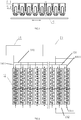
- each of the air ducts 12 comprises a high-pressure air duct 5 located at an inner side and a low-pressure air duct 6 located at an outer side.
- a center of an air-outflow end face of each air duct 12 is provided with a plurality of said air nozzles 15 arranged along a longitudinal direction of the air duct 12.
- the air nozzles 15 is in communication with an internal passage 5-1 of the high-pressure air duct 5.
- the two arc-shaped air outlets 4 of each air nozzle 15 are arranged along a direction that is perpendicular to the longitudinal direction of the air duct 12; both sides of the air nozzle 15 are respectively provided with a plurality of air exits 6-2 arranged along the longitudinal direction of the air duct 12, the air exits 6-2 are in communication with the internal passage 6-1 of the low-pressure air duct 6.
- the compressed air supply unit comprises a high-pressure air supply device 13 and a low-pressure air supply device 14, wherein the high-pressure air supply device 13 is connected to the internal passage 5-1 of each high-pressure air duct 5 through air supply lines.
- the high-pressure air supply device 13 comprises components such as an air compressor, an air storage tank, an air purification can and the air supply lines, the high-pressure air supply device 13 is used for supplying high-pressure air into each high-pressure air duct 5.
- the air supply lines of the high-pressure air supply device 13 comprises a first high-pressure air supply line 131 and a second high-pressure air supply line 132 connected in series: each of the high-pressure air supply line 131 and the second high-pressure air supply line 132 comprises a plurality of high-pressure air supply branches 1311 connected in series; the high-pressure air supply branches 1311 of the first high-pressure air supply line 131 are each connected respectively with one end of the high-pressure air duct 5 of each air duct 12; the high-pressure air supply branches 1311 of the second high-pressure air supply line 132 are each connected respectively with another end of the high-pressure air duct 5 of each air duct 12.
- the high-pressure air enters the internal passage 5-1 of each high-pressure air duct 5 from both ends of a corresponding air duct 12; the low-pressure air supply device 14 is connected to the internal passage 6-1 of each low-pressure air duct 6 through an air supply line.
- the low-pressure air supply device 14 comprises components such as an air blower, an air box, an air purification can and the air supply line, the low-pressure air supply device 14 is used for supplying low-pressure air to each low-pressure air duct 6.
- the air supply line is a low-pressure air supply line 141;
- the low-pressure air supply line comprises a plurality of low-pressure air supply branches 1411 connected in series;
- the low-pressure air supply branches 1411 of the low-pressure air supply line 141 are each connected respectively with one end of the low-pressure air duct 6 of each air duct 12. Therefore, the low-pressure air enters the internal passage 6-1 of each low-pressure air duct 6 from one end of each air duct 12.
- the high-pressure air in the above-mentioned high-pressure air duct 5 has great pressure but small volume when blowing out from the air nozzles 15;
- the low-pressure air in the low-pressure air duct 6 has small pressure but high volume when blowing out from the air exits 6-2.
- the device utilizing air for tempered glass cooling comprises a plurality of air ducts 12. These air ducts 12 are arranged along the movement direction of the tampered glass 9. During operation, the tempered glass 9 is subject to a large amount of high-pressure air sending out from the air nozzles 15 and the low-pressure air sending out from the air exits 6-2 to achieve cooling effect.
- the high-pressure air duct 5 and the low-pressure air duct 6 connect with each other at a side wall corresponding to the air-outflow end face.
- a middle of this air-outflow end face is a horizontal section 7.
- the air nozzles 15 are provided on this horizontal section 7; the two sides of the middle of this air-outflow end face are sloping sections 8 respectively, the air exits 6-2 are provided on the sloping sections 8.
- the housing body 1 in the air nozzle 15 is partially formed as a one whole piece with the air-outflow end face of the high-pressure air duct 5.
- the inner cavity 1-1 of the air nozzle 15 is provided within a wall body of the high-pressure air duct 5 corresponding to the air-outflow end face.
- the inner cavity 1-1 of the air nozzle 15 communicates with the internal passage 5-1 of the high-pressure air duct 5.
- the high-pressure air duct 5 and the low-pressure air duct 6 are made by extrusion process.
- the inner cavity 1-1 is obtained by a numerical control process.
- the air nozzle 15 configured as above can eliminate the procedures of manufacturing an independent housing body 1 and assembling the housing body 1, thereby saving costs.
- a shape that the two arc-shaped air outlets 4 of each air nozzle 15 project onto a glass 9 surface is in a bracket shape (i.e. " () " shape); a plurality of “ () " shapes projected by a plurality of air nozzles 15 are connected in sequence, achievable by setting the distance between the air nozzles 15 and the taper of the tapered air guiding section 3.
- the air exits 6-2 are located on both sides of the air nozzles 15.
- the air-outflow direction of one row of air exits 6-2 forms an included angle of about about 45° with the air-outflow direction of another row of air exits 6-2.
- the projections of the shapes of the two rows of air exits 6-2 on the glass 9 surface are located on both sides of the " () " shape projection respectively.
- high-pressure air blows out from the air nozzles 15 at the middle of the air-outflow end face, and low-pressure air blows out from the air exits 6-2 at both sides of the middle of the air-outflow end face.
- the two types of cooling air can be mixed together or used separately.
- the working principle of the device utilizing air for tempered glass cooling according to the present invention is as follows: With reference to FIGS. 1, 2 and 15 , during operation, many air ducts 12 span across the top of the glass 9 along a width direction of the glass 9.
- the high-pressure air supply device 13 supplies high-pressure air into the internal passage 5-1 of each high-pressure air duct 5 through air supply lines.
- the low-pressure air supply device 14 supplies low-pressure air into the internal passage 6-1 of each low-pressure air duct 6 through air supply lines; wherein the high-pressure air is blown out from each air nozzle 15.
- the compressed air flows forward in a gradual widening angle, and is then divided into two streams discharging out from the two arc-shaped air outlets 4 respectively under the separation of the partition, forming two arc-shaped wind bands with uniform pressure and uniform speed that hit against the glass to be rapidly cooled so as to perform uniform cooling of the glass surface.
- each air duct 12 the high-pressure air blown out from the air nozzles 15 forms a continuous wind band 10 of high-pressure cooling air; low-pressure air is blown out from the air exits; the low-pressure air blown out from the air exits 6-2 in each air duct 12 forms two wind bands 11 of low-pressure cooling air located at both sides of the wind band 10 of high-pressure cooling air on the glass surface.
- the glass 9 at high temperature moves back and forth below the air ducts 12 for rapid cooling by the above-mentioned wind band 10 of high-pressure cooling air and wind bands 11 of low-pressure cooling air.
Landscapes
- Chemical & Material Sciences (AREA)
- Physics & Mathematics (AREA)
- Thermal Sciences (AREA)
- Engineering & Computer Science (AREA)
- Materials Engineering (AREA)
- Organic Chemistry (AREA)
- Re-Forming, After-Treatment, Cutting And Transporting Of Glass Products (AREA)
Claims (9)
- Dispositif utilisant de l'air pour refroidir un verre trempé, comprenant une unité d'alimentation d'air comprimé, des conduites d'air (12) qui sont reliées à l'unité d'alimentation d'air comprimé, et des buses d'air (15) situées sur les conduites d'air (12), dans lequel
chacune des buses d'air (15) comprend un corps de boîtier (1) et un corps incorporé (2) situé dans le corps de boîtier (1), dans lequel un côté intérieur du corps de boîtier (1) est muni d'une cavité interne (1-1) pour monter le corps incorporé (2), un passage de guidage d'air fuselé (3) s'élargissant progressivement vers l'extérieur est formé entre une paroi externe du corps incorporé (2) et une surface de cavité interne ; une extrémité distale du passage de guidage d'air fuselé (3) forme deux sorties d'air en forme d'arc (4) opposées l'une à l'autre ; une cloison est disposée entre les extrémités opposées des deux sorties d'air en forme d'arc (4) pour séparer les deux sorties d'air en forme d'arc ;
chacune des conduites d'air (12) comprend une conduite d'air à haute pression (5) située au niveau d'un côté intérieur et une conduite d'air à basse pression (6) située au niveau d'un côté extérieur ; un centre d'une face d'extrémité d'échappement d'air de chaque conduite d'air (12) est fourni avec une pluralité desdites buses d'air (15) agencées le long d'une direction longitudinale de la conduite d'air (12) ; les buses d'air (15) sont en communication avec un passage interne (5-1) de la conduite d'air à haute pression (5) ; les deux sorties d'air en forme d'arc (4) de chaque buse d'air (15) sont agencées le long d'une direction qui est perpendiculaire à la direction longitudinale de la conduite d'air (12) ; les deux côtés de la buse d'air (15) sont respectivement munis d'une pluralité de sorties d'air (6-2) agencées le long de la direction longitudinale de la conduite d'air, les sorties d'air (6-2) sont en communication avec un passage interne (6-1) de la conduite d'air à basse pression (6) ;
l'unité d'alimentation d'air comprimé comprend un dispositif d'alimentation d'air à haute pression (13) et un dispositif d'alimentation d'air à basse pression (14), le dispositif d'alimentation d'air à haute pression (13) est relié au passage interne (5-1) de chaque conduite d'air à pression élevée (5) par l'intermédiaire des lignes d'alimentation d'air ; le dispositif d'alimentation d'air à haute pression (13) comprend un compresseur d'air, une cuve de stockage d'air, une boîte de purification d'air et des lignes d'alimentation d'air ; le dispositif d'alimentation d'air à haute pression (13) est utilisé pour alimenter de l'air à haute pression dans chaque conduite d'air à haute pression (5) ;
le dispositif d'alimentation d'air à basse pression (14) est relié au passage interne (6-1) de chaque conduite d'air à haute pression (6) par l'intermédiaire d'une ligne d'alimentation d'air ; le dispositif d'alimentation d'air à basse pression (14) comprend une souffleuse d'air, une boîte à vent, une boîte de purification d'air et la ligne d'alimentation d'air ; le dispositif d'alimentation d'air à basse pression (14) est utilisé pour alimenter de l'air à basse pression vers chaque conduite d'air à basse pression (6) ;
dans lequel
les lignes d'alimentation d'air du dispositif d'alimentation d'air à haute pression (13) comprennent une première ligne d'alimentation d'air à haute pression (131) et une seconde ligne d'alimentation d'air à haute pression (132) reliées en série ; chacune de la ligne d'alimentation d'air à haute pression (131) et de la seconde ligne d'alimentation d'air à haute pression (132) comprend une pluralité de branches d'alimentation d'air à haute pression (1311) reliées en série ; les branches d'alimentation d'air à haute pression (1311) de la première ligne d'alimentation d'air à haute pression (131) sont chacune reliées respectivement à une extrémité de la conduite d'air à haute pression (5) de chaque conduite d'air (12) ; les branches d'alimentation d'air à haute pression (1311) de la seconde ligne d'alimentation d'air à haute pression (132) sont chacune reliées respectivement à une autre extrémité de la conduite d'air à haute pression (5) de chaque conduite d'air (12), de sorte que l'air à haute pression entre dans le passage interne (5-1) de chaque conduite d'air à haute pression (5) à partir des deux extrémités de chaque conduite d'air (12) ;
la ligne d'alimentation d'air du dispositif d'alimentation d'air à basse pression (14) est une ligne d'alimentation d'air à basse pression (141) ; la ligne d'alimentation d'air à basse pression (141) comprend une pluralité de branches d'alimentation d'air à basse pression (1311) reliées en série ; les branches d'alimentation d'air à basse pression (1411) de la ligne d'alimentation d'air à basse pression (141) sont chacune reliées respectivement à une extrémité de la conduite d'air à basse pression (6) de chaque conduite d'air (12), de sorte que l'air à basse pression entre dans le passage interne (6-1) de chaque conduite d'air à basse pression (6) à partir d'une extrémité de chaque conduite d'air (12). - Dispositif utilisant de l'air pour refroidir un verre trempé selon la revendication 1, dans lequel la cavité interne (1-1) du corps de boitier (1) est formée par une section d'entrée d'air (1-3), une section de guidage d'air (1-2) et une section de sortie d'air (1-4) reliées séquentiellement ; le corps incorporé (2) est formé en reliant un corps fuselé (2-1) et un corps de séparation (2-2), dans lequel le corps fuselé (2-1) correspond à et s'intègre dans une section de guidage d'air (1-2) ; un espace entre une paroi externe du corps fuselé (2-1) et une surface de la section de guidage d'air forme le passage de guidage d'air fuselé (3) ; une dimension radiale de la section de sortie d'air (1-4) est plus grande que le diamètre le plus grand de la section de guidage d'air (1-2) ; le corps de séparation (2-2) correspond à et s'intègre sur une partie supérieure de la section de sortie d'air (1-4) ; le corps de séparation (2-2) forme la cloison.
- Dispositif utilisant de l'air pour refroidir un verre trempé selon la revendication 2, dans lequel une section transversale de la section de sortie d'air (1-4) a une forme circulaire ; les surfaces du côté extérieur du corps de séparation (2-2) sont des surfaces en arc circulaires qui correspondent à la section transversale circulaire de la section de sortie d'air (1-4).
- Dispositif utilisant de l'air pour refroidir un verre trempé selon la revendication 2, dans lequel le passage de guidage d'air fuselé (3) a une même surface transversale au niveau de n'importe laquelle de ses sections transversales.
- Dispositif utilisant de l'air pour refroidir un verre trempé selon la revendication 4, dans lequel une conicité de la section de guidage d'air (1-2) est de 30 à 120 degrés ; une conicité du corps fuselé (2-1) est de 35 à 150 degrés.
- Dispositif utilisant de l'air pour refroidir un verre trempé selon la revendication 2, dans lequel une section transversale de la section d'entrée d'air (1-3) est de forme circulaire ; une pointe du corps fuselé (2-1) se projette dans la section d'entrée d'air (1-3) ; la pointe du corps fuselé (2-1) se présente sous la forme d'une tête ronde ; un centre de la pointe coïncide avec une ligne centrale de la section d'entrée d'air (1-3).
- Dispositif utilisant de l'air pour refroidir un verre trempé selon la revendication 1, dans lequel le corps de boitier dans la buse d'air (15) est formé sous forme de pièce unique avec la conduite d'air à haute pression (5) ; une cavité interne de la buse d'air (15) communique avec le passage interne (5-1) de la conduite d'air à haute pression (5).
- Dispositif utilisant de l'air pour refroidir un verre trempé selon la revendication 1, dans lequel une forme que les deux sorties d'air en forme d'arc (4) de chaque buse d'air (15) projette sur une surface de verre dans une direction d'échappement d'air a la forme d'une paire de parenthèses ; de multiples paires de parenthèses projetées par une pluralité de buses d'air (15) sont reliées séquentiellement.
- Dispositif utilisant de l'air pour refroidir un verre trempé selon la revendication 1, dans lequel la conduite d'air à haute pression (5) et la conduite d'air à basse pression (6) sont reliées l'une à l'autre au niveau d'une paroi latérale correspondant à la face d'extrémité d'échappement d'air ; un milieu de la face d'extrémité d'échappement d'air est une section horizontale (7) ; les buses d'air (15) sont fournies sur la section horizontale (7) ; deux côtés du milieu de la face d'extrémité d'échappement d'air sont des sections en pente (8) respectivement, les sorties d'air (6-2) sont fournies sur les sections en pente (8).
Priority Applications (1)
| Application Number | Priority Date | Filing Date | Title |
|---|---|---|---|
| EP16152099.4A EP3196172B1 (fr) | 2016-01-20 | 2016-01-20 | Dispositif à air refroidi pour tremper du verre. |
Applications Claiming Priority (1)
| Application Number | Priority Date | Filing Date | Title |
|---|---|---|---|
| EP16152099.4A EP3196172B1 (fr) | 2016-01-20 | 2016-01-20 | Dispositif à air refroidi pour tremper du verre. |
Publications (2)
| Publication Number | Publication Date |
|---|---|
| EP3196172A1 EP3196172A1 (fr) | 2017-07-26 |
| EP3196172B1 true EP3196172B1 (fr) | 2018-10-17 |
Family
ID=55177872
Family Applications (1)
| Application Number | Title | Priority Date | Filing Date |
|---|---|---|---|
| EP16152099.4A Active EP3196172B1 (fr) | 2016-01-20 | 2016-01-20 | Dispositif à air refroidi pour tremper du verre. |
Country Status (1)
| Country | Link |
|---|---|
| EP (1) | EP3196172B1 (fr) |
Cited By (1)
| Publication number | Priority date | Publication date | Assignee | Title |
|---|---|---|---|---|
| US20210380461A1 (en) * | 2020-06-08 | 2021-12-09 | Glaston Finland Oy | Method and device for tempering glass sheets |
Families Citing this family (4)
| Publication number | Priority date | Publication date | Assignee | Title |
|---|---|---|---|---|
| JP6761103B2 (ja) * | 2016-07-21 | 2020-09-23 | サン−ゴバン グラス フランス | ガラスペインに熱的プレストレスを与えるためのブローボックスのためのノズルストリップ |
| CN109133595A (zh) * | 2018-10-13 | 2019-01-04 | 中航三鑫太阳能光电玻璃有限公司 | 一种薄玻璃风淬冷钢化装置 |
| CN114735929B (zh) * | 2022-05-23 | 2025-01-03 | 秦皇岛市运通玻璃机电技术有限公司 | 一种钢化玻璃弯曲成型装置及生产系统 |
| CN222205052U (zh) * | 2024-02-05 | 2024-12-20 | 洛阳兰迪玻璃机器股份有限公司 | 一种缝隙式吹风的风栅本体、风栅组及玻璃钢化设备 |
Family Cites Families (6)
| Publication number | Priority date | Publication date | Assignee | Title |
|---|---|---|---|---|
| US3293015A (en) * | 1961-09-22 | 1966-12-20 | Pittsburgh Plate Glass Co | Method and apparatus for tempering glass sheets on a gas support bed |
| FI90046C (fi) * | 1992-02-12 | 1993-12-27 | Tamglass Eng Oy | Munstycksarrangemang foer en haerdningsugn foer planglas |
| FI104422B (fi) * | 1998-06-30 | 2000-01-31 | Tamglass Ltd Oy | Menetelmä ja laite lasilevyjen karkaisemiseksi |
| CN2608497Y (zh) | 2003-03-26 | 2004-03-31 | 许涛 | 缝隙式风栅喷嘴 |
| CN203960044U (zh) * | 2014-06-04 | 2014-11-26 | 佛山市索奥斯玻璃技术有限公司 | 一种钢化玻璃风冷风嘴以及包含该风嘴的风管 |
| CN103992027B (zh) * | 2014-06-04 | 2016-08-24 | 佛山市索奥斯玻璃技术有限公司 | 一种钢化玻璃风冷风嘴以及包含该风嘴的风管 |
-
2016
- 2016-01-20 EP EP16152099.4A patent/EP3196172B1/fr active Active
Non-Patent Citations (1)
| Title |
|---|
| None * |
Cited By (1)
| Publication number | Priority date | Publication date | Assignee | Title |
|---|---|---|---|---|
| US20210380461A1 (en) * | 2020-06-08 | 2021-12-09 | Glaston Finland Oy | Method and device for tempering glass sheets |
Also Published As
| Publication number | Publication date |
|---|---|
| EP3196172A1 (fr) | 2017-07-26 |
Similar Documents
| Publication | Publication Date | Title |
|---|---|---|
| EP3196172B1 (fr) | Dispositif à air refroidi pour tremper du verre. | |
| CN103992027B (zh) | 一种钢化玻璃风冷风嘴以及包含该风嘴的风管 | |
| ITMI20100249U1 (it) | Dispositivo di scambio termico con sistema perfezionato di distribuzione del fluido refrigerante | |
| CA2521088A1 (fr) | Appareil et procede de formation de fibres | |
| BR0204695B1 (pt) | Bocal de pulverização assistido a ar e sistema de pulverização para dirigir um líquido refrigerante num aparelho de fundição de metal | |
| CN104624424A (zh) | 用于带钢冷却的气雾冷却装置 | |
| CN104174670B (zh) | 宽向可变流量的冷却集管 | |
| CN208292866U (zh) | 用于玻璃纤维直接无捻粗纱的拉丝成型装置 | |
| CN202380052U (zh) | 用于带材加热的输送喷箱 | |
| CN107588579A (zh) | 蒸发器及空调系统 | |
| EP3513661B1 (fr) | Structure de buse de jet en forme d'entonnoir allongée | |
| CN104476758A (zh) | 一种用于瓶胚成型的局部冷却机构 | |
| CN203960044U (zh) | 一种钢化玻璃风冷风嘴以及包含该风嘴的风管 | |
| CN212504573U (zh) | 一种玻璃钢化炉冷却风栅 | |
| CN101633557A (zh) | 一种玻璃钢化机组用冷却风栅 | |
| CN204052402U (zh) | 宽向可变流量的冷却集管 | |
| CN106440034B (zh) | 空调器室内机和空调器 | |
| CN111715708B (zh) | 一种用于线材吐丝盘条后均匀冷却装置及其冷却方法 | |
| CN103912949A (zh) | 一种新型纺丝冷却装置及纺丝冷却方法 | |
| KR100547477B1 (ko) | 강판냉각설비용 냉각헤더 | |
| KR101254597B1 (ko) | 원심 주조용 금형 내부 코팅용 분사노즐 | |
| CN208104223U (zh) | 一种新型钢化玻璃风帘装置 | |
| CN212315925U (zh) | 一种玻璃钢化炉分级静压风栅 | |
| CN117923774A (zh) | 一种玻璃钢化工艺中的缝隙式吹风方法及玻璃钢化设备 | |
| CN220597710U (zh) | 一种预冷型化纤纺丝组件 |
Legal Events
| Date | Code | Title | Description |
|---|---|---|---|
| PUAI | Public reference made under article 153(3) epc to a published international application that has entered the european phase |
Free format text: ORIGINAL CODE: 0009012 |
|
| STAA | Information on the status of an ep patent application or granted ep patent |
Free format text: STATUS: REQUEST FOR EXAMINATION WAS MADE |
|
| 17P | Request for examination filed |
Effective date: 20160329 |
|
| AK | Designated contracting states |
Kind code of ref document: A1 Designated state(s): AL AT BE BG CH CY CZ DE DK EE ES FI FR GB GR HR HU IE IS IT LI LT LU LV MC MK MT NL NO PL PT RO RS SE SI SK SM TR |
|
| AX | Request for extension of the european patent |
Extension state: BA ME |
|
| RIN1 | Information on inventor provided before grant (corrected) |
Inventor name: ZHOU, JUNSHAN |
|
| GRAP | Despatch of communication of intention to grant a patent |
Free format text: ORIGINAL CODE: EPIDOSNIGR1 |
|
| STAA | Information on the status of an ep patent application or granted ep patent |
Free format text: STATUS: GRANT OF PATENT IS INTENDED |
|
| INTG | Intention to grant announced |
Effective date: 20180709 |
|
| GRAS | Grant fee paid |
Free format text: ORIGINAL CODE: EPIDOSNIGR3 |
|
| GRAA | (expected) grant |
Free format text: ORIGINAL CODE: 0009210 |
|
| STAA | Information on the status of an ep patent application or granted ep patent |
Free format text: STATUS: THE PATENT HAS BEEN GRANTED |
|
| AK | Designated contracting states |
Kind code of ref document: B1 Designated state(s): AL AT BE BG CH CY CZ DE DK EE ES FI FR GB GR HR HU IE IS IT LI LT LU LV MC MK MT NL NO PL PT RO RS SE SI SK SM TR |
|
| REG | Reference to a national code |
Ref country code: GB Ref legal event code: FG4D |
|
| REG | Reference to a national code |
Ref country code: CH Ref legal event code: EP |
|
| REG | Reference to a national code |
Ref country code: IE Ref legal event code: FG4D |
|
| REG | Reference to a national code |
Ref country code: DE Ref legal event code: R096 Ref document number: 602016006337 Country of ref document: DE Ref country code: AT Ref legal event code: REF Ref document number: 1053798 Country of ref document: AT Kind code of ref document: T Effective date: 20181115 |
|
| REG | Reference to a national code |
Ref country code: NL Ref legal event code: MP Effective date: 20181017 |
|
| REG | Reference to a national code |
Ref country code: LT Ref legal event code: MG4D |
|
| REG | Reference to a national code |
Ref country code: AT Ref legal event code: MK05 Ref document number: 1053798 Country of ref document: AT Kind code of ref document: T Effective date: 20181017 |
|
| PG25 | Lapsed in a contracting state [announced via postgrant information from national office to epo] |
Ref country code: NL Free format text: LAPSE BECAUSE OF FAILURE TO SUBMIT A TRANSLATION OF THE DESCRIPTION OR TO PAY THE FEE WITHIN THE PRESCRIBED TIME-LIMIT Effective date: 20181017 |
|
| PGFP | Annual fee paid to national office [announced via postgrant information from national office to epo] |
Ref country code: LU Payment date: 20190122 Year of fee payment: 4 |
|
| PG25 | Lapsed in a contracting state [announced via postgrant information from national office to epo] |
Ref country code: FI Free format text: LAPSE BECAUSE OF FAILURE TO SUBMIT A TRANSLATION OF THE DESCRIPTION OR TO PAY THE FEE WITHIN THE PRESCRIBED TIME-LIMIT Effective date: 20181017 Ref country code: LV Free format text: LAPSE BECAUSE OF FAILURE TO SUBMIT A TRANSLATION OF THE DESCRIPTION OR TO PAY THE FEE WITHIN THE PRESCRIBED TIME-LIMIT Effective date: 20181017 Ref country code: HR Free format text: LAPSE BECAUSE OF FAILURE TO SUBMIT A TRANSLATION OF THE DESCRIPTION OR TO PAY THE FEE WITHIN THE PRESCRIBED TIME-LIMIT Effective date: 20181017 Ref country code: PL Free format text: LAPSE BECAUSE OF FAILURE TO SUBMIT A TRANSLATION OF THE DESCRIPTION OR TO PAY THE FEE WITHIN THE PRESCRIBED TIME-LIMIT Effective date: 20181017 Ref country code: AT Free format text: LAPSE BECAUSE OF FAILURE TO SUBMIT A TRANSLATION OF THE DESCRIPTION OR TO PAY THE FEE WITHIN THE PRESCRIBED TIME-LIMIT Effective date: 20181017 Ref country code: BG Free format text: LAPSE BECAUSE OF FAILURE TO SUBMIT A TRANSLATION OF THE DESCRIPTION OR TO PAY THE FEE WITHIN THE PRESCRIBED TIME-LIMIT Effective date: 20190117 Ref country code: NO Free format text: LAPSE BECAUSE OF FAILURE TO SUBMIT A TRANSLATION OF THE DESCRIPTION OR TO PAY THE FEE WITHIN THE PRESCRIBED TIME-LIMIT Effective date: 20190117 Ref country code: IS Free format text: LAPSE BECAUSE OF FAILURE TO SUBMIT A TRANSLATION OF THE DESCRIPTION OR TO PAY THE FEE WITHIN THE PRESCRIBED TIME-LIMIT Effective date: 20190217 Ref country code: LT Free format text: LAPSE BECAUSE OF FAILURE TO SUBMIT A TRANSLATION OF THE DESCRIPTION OR TO PAY THE FEE WITHIN THE PRESCRIBED TIME-LIMIT Effective date: 20181017 Ref country code: ES Free format text: LAPSE BECAUSE OF FAILURE TO SUBMIT A TRANSLATION OF THE DESCRIPTION OR TO PAY THE FEE WITHIN THE PRESCRIBED TIME-LIMIT Effective date: 20181017 |
|
| PGFP | Annual fee paid to national office [announced via postgrant information from national office to epo] |
Ref country code: NL Payment date: 20190121 Year of fee payment: 4 Ref country code: IE Payment date: 20190122 Year of fee payment: 4 |
|
| PG25 | Lapsed in a contracting state [announced via postgrant information from national office to epo] |
Ref country code: PT Free format text: LAPSE BECAUSE OF FAILURE TO SUBMIT A TRANSLATION OF THE DESCRIPTION OR TO PAY THE FEE WITHIN THE PRESCRIBED TIME-LIMIT Effective date: 20190217 Ref country code: GR Free format text: LAPSE BECAUSE OF FAILURE TO SUBMIT A TRANSLATION OF THE DESCRIPTION OR TO PAY THE FEE WITHIN THE PRESCRIBED TIME-LIMIT Effective date: 20190118 Ref country code: RS Free format text: LAPSE BECAUSE OF FAILURE TO SUBMIT A TRANSLATION OF THE DESCRIPTION OR TO PAY THE FEE WITHIN THE PRESCRIBED TIME-LIMIT Effective date: 20181017 Ref country code: SE Free format text: LAPSE BECAUSE OF FAILURE TO SUBMIT A TRANSLATION OF THE DESCRIPTION OR TO PAY THE FEE WITHIN THE PRESCRIBED TIME-LIMIT Effective date: 20181017 Ref country code: AL Free format text: LAPSE BECAUSE OF FAILURE TO SUBMIT A TRANSLATION OF THE DESCRIPTION OR TO PAY THE FEE WITHIN THE PRESCRIBED TIME-LIMIT Effective date: 20181017 |
|
| REG | Reference to a national code |
Ref country code: DE Ref legal event code: R097 Ref document number: 602016006337 Country of ref document: DE |
|
| PG25 | Lapsed in a contracting state [announced via postgrant information from national office to epo] |
Ref country code: IT Free format text: LAPSE BECAUSE OF FAILURE TO SUBMIT A TRANSLATION OF THE DESCRIPTION OR TO PAY THE FEE WITHIN THE PRESCRIBED TIME-LIMIT Effective date: 20181017 Ref country code: CZ Free format text: LAPSE BECAUSE OF FAILURE TO SUBMIT A TRANSLATION OF THE DESCRIPTION OR TO PAY THE FEE WITHIN THE PRESCRIBED TIME-LIMIT Effective date: 20181017 Ref country code: DK Free format text: LAPSE BECAUSE OF FAILURE TO SUBMIT A TRANSLATION OF THE DESCRIPTION OR TO PAY THE FEE WITHIN THE PRESCRIBED TIME-LIMIT Effective date: 20181017 |
|
| PLBE | No opposition filed within time limit |
Free format text: ORIGINAL CODE: 0009261 |
|
| STAA | Information on the status of an ep patent application or granted ep patent |
Free format text: STATUS: NO OPPOSITION FILED WITHIN TIME LIMIT |
|
| PG25 | Lapsed in a contracting state [announced via postgrant information from national office to epo] |
Ref country code: SM Free format text: LAPSE BECAUSE OF FAILURE TO SUBMIT A TRANSLATION OF THE DESCRIPTION OR TO PAY THE FEE WITHIN THE PRESCRIBED TIME-LIMIT Effective date: 20181017 Ref country code: EE Free format text: LAPSE BECAUSE OF FAILURE TO SUBMIT A TRANSLATION OF THE DESCRIPTION OR TO PAY THE FEE WITHIN THE PRESCRIBED TIME-LIMIT Effective date: 20181017 Ref country code: SK Free format text: LAPSE BECAUSE OF FAILURE TO SUBMIT A TRANSLATION OF THE DESCRIPTION OR TO PAY THE FEE WITHIN THE PRESCRIBED TIME-LIMIT Effective date: 20181017 Ref country code: RO Free format text: LAPSE BECAUSE OF FAILURE TO SUBMIT A TRANSLATION OF THE DESCRIPTION OR TO PAY THE FEE WITHIN THE PRESCRIBED TIME-LIMIT Effective date: 20181017 |
|
| 26N | No opposition filed |
Effective date: 20190718 |
|
| REG | Reference to a national code |
Ref country code: BE Ref legal event code: MM Effective date: 20190131 |
|
| PG25 | Lapsed in a contracting state [announced via postgrant information from national office to epo] |
Ref country code: SI Free format text: LAPSE BECAUSE OF FAILURE TO SUBMIT A TRANSLATION OF THE DESCRIPTION OR TO PAY THE FEE WITHIN THE PRESCRIBED TIME-LIMIT Effective date: 20181017 |
|
| PG25 | Lapsed in a contracting state [announced via postgrant information from national office to epo] |
Ref country code: BE Free format text: LAPSE BECAUSE OF NON-PAYMENT OF DUE FEES Effective date: 20190131 |
|
| PG25 | Lapsed in a contracting state [announced via postgrant information from national office to epo] |
Ref country code: TR Free format text: LAPSE BECAUSE OF FAILURE TO SUBMIT A TRANSLATION OF THE DESCRIPTION OR TO PAY THE FEE WITHIN THE PRESCRIBED TIME-LIMIT Effective date: 20181017 |
|
| PG25 | Lapsed in a contracting state [announced via postgrant information from national office to epo] |
Ref country code: MT Free format text: LAPSE BECAUSE OF NON-PAYMENT OF DUE FEES Effective date: 20190120 |
|
| PG25 | Lapsed in a contracting state [announced via postgrant information from national office to epo] |
Ref country code: MC Free format text: LAPSE BECAUSE OF NON-PAYMENT OF DUE FEES Effective date: 20200131 |
|
| PG25 | Lapsed in a contracting state [announced via postgrant information from national office to epo] |
Ref country code: LU Free format text: LAPSE BECAUSE OF NON-PAYMENT OF DUE FEES Effective date: 20200120 |
|
| PG25 | Lapsed in a contracting state [announced via postgrant information from national office to epo] |
Ref country code: IE Free format text: LAPSE BECAUSE OF NON-PAYMENT OF DUE FEES Effective date: 20200120 |
|
| PG25 | Lapsed in a contracting state [announced via postgrant information from national office to epo] |
Ref country code: CY Free format text: LAPSE BECAUSE OF FAILURE TO SUBMIT A TRANSLATION OF THE DESCRIPTION OR TO PAY THE FEE WITHIN THE PRESCRIBED TIME-LIMIT Effective date: 20181017 |
|
| PG25 | Lapsed in a contracting state [announced via postgrant information from national office to epo] |
Ref country code: HU Free format text: LAPSE BECAUSE OF FAILURE TO SUBMIT A TRANSLATION OF THE DESCRIPTION OR TO PAY THE FEE WITHIN THE PRESCRIBED TIME-LIMIT; INVALID AB INITIO Effective date: 20160120 |
|
| PG25 | Lapsed in a contracting state [announced via postgrant information from national office to epo] |
Ref country code: MK Free format text: LAPSE BECAUSE OF FAILURE TO SUBMIT A TRANSLATION OF THE DESCRIPTION OR TO PAY THE FEE WITHIN THE PRESCRIBED TIME-LIMIT Effective date: 20181017 |
|
| PGFP | Annual fee paid to national office [announced via postgrant information from national office to epo] |
Ref country code: CH Payment date: 20250201 Year of fee payment: 10 |
|
| PGFP | Annual fee paid to national office [announced via postgrant information from national office to epo] |
Ref country code: GB Payment date: 20251222 Year of fee payment: 11 |
|
| REG | Reference to a national code |
Ref country code: CH Ref legal event code: U11 Free format text: ST27 STATUS EVENT CODE: U-0-0-U10-U11 (AS PROVIDED BY THE NATIONAL OFFICE) Effective date: 20260201 |
|
| PGFP | Annual fee paid to national office [announced via postgrant information from national office to epo] |
Ref country code: DE Payment date: 20260121 Year of fee payment: 11 |
|
| PGFP | Annual fee paid to national office [announced via postgrant information from national office to epo] |
Ref country code: FR Payment date: 20260123 Year of fee payment: 11 |