EP3197607B1 - Plaque distributrice, dispositif de stockage, agencement de cartouche, appareil de distribution et leur utilisation - Google Patents
Plaque distributrice, dispositif de stockage, agencement de cartouche, appareil de distribution et leur utilisation Download PDFInfo
- Publication number
- EP3197607B1 EP3197607B1 EP15763637.4A EP15763637A EP3197607B1 EP 3197607 B1 EP3197607 B1 EP 3197607B1 EP 15763637 A EP15763637 A EP 15763637A EP 3197607 B1 EP3197607 B1 EP 3197607B1
- Authority
- EP
- European Patent Office
- Prior art keywords
- inlet
- storage container
- head plate
- outlet
- passage
- Prior art date
- Legal status (The legal status is an assumption and is not a legal conclusion. Google has not performed a legal analysis and makes no representation as to the accuracy of the status listed.)
- Active
Links
Images


Classifications
-
- B—PERFORMING OPERATIONS; TRANSPORTING
- B05—SPRAYING OR ATOMISING IN GENERAL; APPLYING FLUENT MATERIALS TO SURFACES, IN GENERAL
- B05C—APPARATUS FOR APPLYING FLUENT MATERIALS TO SURFACES, IN GENERAL
- B05C17/00—Hand tools or apparatus using hand held tools, for applying liquids or other fluent materials to, for spreading applied liquids or other fluent materials on, or for partially removing applied liquids or other fluent materials from, surfaces
- B05C17/005—Hand tools or apparatus using hand held tools, for applying liquids or other fluent materials to, for spreading applied liquids or other fluent materials on, or for partially removing applied liquids or other fluent materials from, surfaces for discharging material from a reservoir or container located in or on the hand tool through an outlet orifice by pressure without using surface contacting members like pads or brushes
- B05C17/00503—Details of the outlet element
- B05C17/00506—Means for connecting the outlet element to, or for disconnecting it from, the hand tool or its container
-
- B—PERFORMING OPERATIONS; TRANSPORTING
- B05—SPRAYING OR ATOMISING IN GENERAL; APPLYING FLUENT MATERIALS TO SURFACES, IN GENERAL
- B05C—APPARATUS FOR APPLYING FLUENT MATERIALS TO SURFACES, IN GENERAL
- B05C17/00—Hand tools or apparatus using hand held tools, for applying liquids or other fluent materials to, for spreading applied liquids or other fluent materials on, or for partially removing applied liquids or other fluent materials from, surfaces
- B05C17/005—Hand tools or apparatus using hand held tools, for applying liquids or other fluent materials to, for spreading applied liquids or other fluent materials on, or for partially removing applied liquids or other fluent materials from, surfaces for discharging material from a reservoir or container located in or on the hand tool through an outlet orifice by pressure without using surface contacting members like pads or brushes
- B05C17/00553—Hand tools or apparatus using hand held tools, for applying liquids or other fluent materials to, for spreading applied liquids or other fluent materials on, or for partially removing applied liquids or other fluent materials from, surfaces for discharging material from a reservoir or container located in or on the hand tool through an outlet orifice by pressure without using surface contacting members like pads or brushes with means allowing the stock of material to consist of at least two different components
Definitions
- the present invention relates to a cartridge arrangement, to a dispensing apparatus comprising the cartridge arrangement and a mixer device, and the usage of the cartridge arrangement, and the dispensing apparatus.
- the present invention relates to a cartridge arrangement for a dispensing apparatus for dispensing at least two flowable components, to a dispensing apparatus comprising for dispensing at least two flowable components using the cartridge arrangement, and their usage.
- a static or dynamic mixer on the one hand and plural storage containers on the other hand - are used in a variety of technical fields.
- the field of storing, mixing, and/or dispensing at least two flowable components in particular at least one of a sealant and an adhesive and/or for at least one of installing, fixing, gluing, sealing, and repairing a window, in particular a wind shield or wind screen of a vehicle, in particular in a car, is of high interest, too.
- the individual components usually have to remain separated from each other until the intended usage is begun. Upon use, the components are mixed and dispensed so that e.g. hardening can subsequently take place by a chemical reaction.
- Such mixers are often designed for single use because in general cleaning is difficult after hardening or after any other chemical reaction of the components involved.
- Storage container devices for storing and supplying the flowable components on the one hand and the mixer device on the other hand therefore often attached to a mediating means such as a head plate.
- head plates are - besides the mixers - are often part of a dispensing apparatus which further includes cartridges or other storage chambers for storing and supplying the respective components.
- the individual components are dispensed from the chambers by means of a plunger or by means of a drivable piston, in order to move the components into the mixer.
- the components are intimately mixed and exit the mixer through an outlet opening thereof as a homogeneous mixture of the involved components.
- the chambers can be designed, for example, as rigid cartridges which are inserted directly into the dispensing apparatus.
- the cartridges can, for example, each have a piston as a base which is moved in the cartridge by exerting pressure to dispense the respective component.
- the cartridges are inserted into a support cartridge of the dispensing apparatus. Pressure is exerted on them by a plunger or by a piston. Provision can be made in this respect that the thin-walled cartridge collapses on dispensing within the support cartridge.
- US 4,981,241 relates to a dual dispenser cartridge, having two interlocked storages cylinders, separated by double walls, arranged axially parallel side-by-side, and each comprising one front end discharging opening, wherein both discharging openings are located next to each other on the common center line of both storage cylinders.
- the dual dispenser cartridge comprises a transition member, positioned ahead of the two storage cylinders.
- a permanent, axial push-fit connection between the transition member and the two storage cylinders is accomplished by means of a snap lock. This push-fit connection, however, does not provide a secure engagement against rotation but merely an axially snap-in connection.
- Document DE 296 03 416 U1 relates to a cartridge for two-component materials. If a handle is actuated, foil bags are opened via cutting elements so that the material is introduced in a mixer. These cutting elements cannot establish a secure engagement with the flexible foil bag so that, again, a rotation is not securely blocked.
- Document EP 2 520 360 A1 discloses a mixer for mixing at least two flowable components and a dispensing apparatus, wherein first and second containers for storing and supplying first and second flowable components are connected with their outlet passages to cooperating inlet passages of the mixer.
- the coupling elements between the cartridges or storage containers on the one hand and those of the head plate on the other hand often have a circular geometry. Therefore, it may be possible that even after having coupled a cartridge or a storage container with its opening region - in particular an outlet - to the opening region of the mixer - in particular to an inlet - there remains a risk in the already coupled state of an inadvertent relative rotational motion be-tween the storage container or the cartridge during operation. This is in particular a risk in case that a piston with a self-cutting thread is used for driving the supply process for one or plural of the flowable components.
- the object underlying the present invention is solved by a cartridge arrangement according to independent claim 1, by a dispensing apparatus according to claim 16, and their usage defined according to independent claim 17.
- a cartridge arrangement for a dispensing apparatus for dispensing at least two flowable components comprising a head plate device is provided.
- the head plate device comprises at least two separate outlet openings for respectively dispensing the at least two flowable components and at least two separate inlet passages through which the at least two flowable components can be introduced and flowed through separately from one another to a respective one of the outlet openings.
- Each of said inlet passages of the head plate device is designed for - preferably sealing - cooperation with one respective outlet passage of storage container device.
- At least one of the inlet passages of the head plate device comprises an inlet opening region of essentially circularly shaped cross-section with at least one of an inner periphery and an outer periphery.
- At least one of the inner periphery and the outer periphery comprises at least one engaging element. The at least one engaging element extends radially from the respective inner or outer periphery.
- the provided engaging elements may additionally or alternatively help an easy and reliable attachment of a storage container device on the head plate, e.g. by means of a snap, lock, latch, or click into place action. Thereby, an axial motion between attached storage container devices and the head plate and thus an unintended separation can be suppressed.
- the engaging element (engaging elements) is (are) configured to allow (at least to a certain extent) axial movement between the storage container device and the head plate (in a coupled state).
- the engaging element (engaging elements) is (are) configured to allow separation of the storage container device and the head plate (only) by an axial movement.
- the engaging element is (are) adapted to hinder rotational movement (block rotational movement) between the storage container device and head plate and allow an axial movement between these parts (optionally until complete separation), in their coupled state.
- storage container device and head plate may be connected by a press-fit.
- connection and separation of storage container device and head plate may be very simple and reliable.
- the engaging element (the engaging elements) hinders (hinder) a rotational movement, which can be sufficient to avoid a decoupling of storage container device and head plate.
- a head plate or head plate device in the sense of the present invention is an element and in particular a plate to which storage containers for storing and supplying a component can be or are attached.
- the storage containers are attached and fixed to the head plate and the arrangement formed by the head plate and the storage containers attached and fixed thereto is offered and e.g. sold to an end consumer. Such an arrangement is called a cartridge arrangement.
- the head plate may also be referred to as an intermediate part or portion as in practice it is located between the attached storage containers and a mixer to which the components are fed for mixing.
- a storage container device may form a storage chamber by offering a space for directly receiving and storing a flowable component, thereby operating e.g. as self-supporting cartridge.
- a storage container device may form a storage chamber by offering a space for receiving a bellows type container, a foil type container, a collapsible cartridge or any other container, thereby operating as a supporting cartridge which only indirectly stores a flowable component.
- the storage container device in particular a cartridge may have rigid walls, in particular self-supporting walls.
- a plunger, a piston, in particular comprising a self-cutting thread,or any other suitable means for initiating the components' flow may be provided, even when they are not explicitly shown in the figures. Because of the underlying principle of sealing cooperation of the inlet passages of the mixer device with respect to outlet passages of the storage container device, this requires an engagement of the outlet passage of the storage container device with the engaging element located at or on the periphery of the inlet passage in question.
- the at least one engaging element is configured to engage with a cooperating and essentially complimentary engaging element of a corresponding outlet passage of a storage container device in a state where the inlet passage of the head plate device sealingly cooperates with the respective outlet passage of the storage container device.
- a snap, lock, latch, or click into place action and/or a form fit, a press fit, and/or a force fit thereof can be achieved.
- the head plate device has opposed first and second sides, wherein the at least two separate inlet passages are formed on one of the first and second sides, wherein the at least the at least two separate outlet openings are formed on the other one of the first and second sides, and wherein in particular the number of inlet passages is identical to the number of outlet openings.
- the present invention provides a cartridge arrangement for a dispensing apparatus with at least two storage containers which are configured for storing a flowable component.
- At least one of the storage container devices provides or comprises a storage chamber for storing a flowable component and an outlet passage through which the flowable component can be discharged.
- the outlet passage of the storage container device is designed for - preferably sealing - cooperation with a respective inlet passage of a head plate device.
- the outlet passage of the storage container device comprises an outlet opening region of essentially circularly shaped cross-section with at least one of an inner periphery and an outer periphery.
- At least one of the inner periphery and the outer periphery comprises at least one engaging element.
- the at least one engaging element extends radially from respective inner periphery or outer periphery.
- the at least one engaging element of the outlet passage of the storage container device is configured to engage with a cooperating and essentially complimentary engaging element of a corresponding inlet passage of a head plate device in a state where the outlet passage of the storage container device - preferably sealingly - cooperates with the respective inlet passage of the head plate device.
- a snap, lock, latch, or click into place action and/or a form fit, a press fit, and a force fit may be achieved.
- a plurality of engaging elements - i.e. at least two - may be provided, wherein a first fraction - i.e. least one - of the plurality engaging elements is configured for achieving said torque proof cooperation be-tween the inlet passage of the head plate device and the respective outlet passage of the storage container device, and wherein a second fraction - i.e. also at least one - of the plurality of engaging elements is configured for achieving an engagement between the inlet passage of the head plate device and the respective out-let passage of the storage container device thereby avoiding an axial movement and an inadvertent spatial separation thereof. Therefore, an advantageous combination of avoiding axial on rotational movement can be achieved.
- a central idea of the present invention is a configuration of the outlet passage of the storage container device and inlet passage of the head plate device so that a rotation, in their coupled state is avoided.
- an axial movement, in their coupled state may be possible.
- the corresponding engaging elements are configured so that a rotation is blocked, whereas an axial movement may be allowed.
- such an axial movement may be also blocked. If an axial movement is - in principle - possible, it may be restricted by certain press-fit (without, in particular, an additional form-fit).
- An engaging element may be formed as a male member protruding either from the inner periphery of the respective inlet or outlet opening region of the respective inlet or outlet passage and radially inwardly or from the outer periphery of the respective inlet or outlet opening region of the respective inlet or outlet passage and radially outwardly.
- an engaging element may be formed as a female member recessing either from the inner periphery of the respective inlet or outlet opening region of the respective inlet or outlet passage and radially outwardly or from the outer periphery of the respective inlet or outlet opening region of the respective inlet or outlet passage and radially inwardly.
- the provided engaging element may be formed as a male protrusion or as a female recess on the respective periphery of an inlet opening region of the inlet passages of a head plate device or of an outlet opening region of an outlet passage of a storage container device.
- a male member as a protrusion in each case protrudes from the periphery at which the protrusion is located: From an outer periphery the protrusion protrudes outwardly in a radial direction and from an inner periphery the protrusion protrudes inwardly in the radial direction.
- a male member may have a rectangular shape and be, preferably, arranged so that two sides of the rectangular shape are in contact with surrounding parts of the head plate device or storage container device, respectively.
- the female member may have a rectangular cross-section, wherein, preferably, two sides of the rectangular cross-section are open.
- a male member if located at the head plate device, may have a first end, facing in the direction of the head plate device and a second end facing in the direction of the storage container device, wherein the first end is in contact with the head plate device and the second end can be inserted into a corresponding female member of the storage container device.
- the engaging element is provided at the storage container device, it is preferred that the first end is free and the second end is in contact with the storage container device. Thereby, a simple and reliable blocking of rotation can be achieved.
- a female member if a female member is located at the head plate device, a first end of the female member (facing in the direction of the head plate device) may have a bottom, whereas a second end of the female member (facing in the direction of the storage container device) is free so that a corresponding male member may be inserted. If the female member is provided at the storage container device, the first end may be open and the second end may be closed by a bottom surface. Thereby, a simple and reliable blocking of rotation can be achieved.
- a female member as a recess located on a respective periphery of an inlet opening region of an inlet passage of a head plate device or of an outlet opening region of an outlet passage of a storage container device recesses on an outer periphery inwardly in radial direction, whereas a recess on an inner periphery recesses outwardly in the radial direction.
- any geometry for the engaging element formed at or on the periphery of the inlet opening region of the inlet passage of the head plate device and at or on the periphery of the outlet opening region of the outlet passage of the storage container device is suitable as far as (i) an engaging operation is possible and (ii) a rotational motion and thereby slippage of the coupled components can be avoided.
- the at least one engaging element is formed as one of (A) a fin element extending axially and/or circumferentially, (B) a slit extending axially and/or circumferentially, (C) an element with one of a polygonal, rectangular, triangular, semicircular and oval cross section in the axial direction each on the respective periphery and extending axially and/or circumferentially.
- a plurality of engaging elements may be provided on at least one of the inner periphery and the outer periphery of at least one of the inlet or outlet opening region of at least one of the inlet and the outlet passages of the head plate device and the storage container device.
- the plurality of engaging elements on a respective periphery of the inlet opening regions of the inlet passages may be formed as a sequence of alternating male and female structures.
- the sequence of alternating male or female structures may appear as an undulation or corrugation when be viewed along the symmetry axis of the underlying inlet opening region.
- individuals of pairs of adjacent engaging elements of the plurality of engaging elements on a respective periphery may be positioned directly adjacent to and in direct contact with each other.
- individuals of pairs of adjacent engaging elements of the plurality of engaging elements on a respective periphery are positioned on a respective periphery, with a gap element between them, formed by a free portion of the respective periphery.
- An intended exertion of form-fit, press-fit or force-fit may be achieved based on the shape of the at least one engaging element on the respective periphery of the respective opening region of the respective passage.
- the shape of a protruding engaging element may provide a tapered configuration with at least one of a reduced height in the radial direction and a reduced width in the circumferential direction, each towards the respective opening region or the opening as such.
- a tapered shape with at least one of a reduced height in radial direction and a reduced width in circumferential direction each towards the respective inlet or outlet opening may be provided.
- a tapered shape with at least one of an increased depth in radial direction and an increased width in circumferential direction each towards the respective inlet or outlet opening may be provided.
- the provision of the engaging element and in particular its shape and/or its position and orientation on the respective periphery may be used as a mechanical coding in order to define a particular assignment of an inlet passage with its inlet opening region to a certain kind of outlet passage and the respective outlet opening region.
- Each of the at least two storage container devices may be filled with material of one of the at least two flowable components.
- the dispensing apparatus comprises a cartridge arrangement according to the present invention, i.e. as defined in any of the appended claims 1 to 15.
- the storage container device or the respective chamber has at least one outlet passage for one of the components.
- the apparatus comprises a mixer device which is attachable or attached to the cartridge arrangement and which is configured for receiving from the cartridge arrangement the at least two flowable components, for mixing the at least two flowable components, and for dispensing the at least two flowable components in a mixed state.
- An involved mixer may be a dynamic mixer having a rotatable mixing element or a static mixer having a static mixing element.
- the cartridge arrangement and the dispensing apparatus are used for storing, mixing, and/or dispensing at least two flowable components, in particular at least one of a sealant and an adhesive and/or for at least one of installing, fixing, gluing, sealing, and repairing a window, in particular a wind shield or wind screen of a vehicle, in particular in a car.
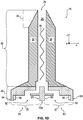
- Figs. 1A and 1B are schematic and cross-sectional side-views of an embodiment of a head plate device 45 before and in cooperation with respective storage container devices.
- Figs. 1C and 1D are schematic and cross-sectional side-views of an embodiment of a head plate device 45 before and in cooperation with a mixer or mixer device10.
- the mixer device 10 is formed by a mixer housing 20 which comprises in an upper part in Figs. 1C , D a mixing part or portion 40 and in the lower part of Fig. 1C , D an intermediate part or portion 45.
- the mixing part 40 of the housing 20 comprises in its interior 25 a mixing element 30.
- This mixing element 30 may be or form a static mixer or a dynamic mixer.
- the mixer housing 20 forms a tip or tip portion 26 with an outlet opening 24 for dispensing the mixture formed within the interior 25 of the mixer device 10 by mixing the at least two flowable components 11, 12.
- the shown head plate device 45 is configured for being coupled on its second or upper side 45b with the mixer device 10; thus, respective engaging elements - as for the attachment of the cartridge container devices 90 - or cooperating threadings or any other means be provided.
- the shown head plate device 45 is configured for being coupled on its first or lower side 45a with a plurality of storage container devices 90 offering respective storage chambers 91, 92 which are not shown here.
- the head plate 45 comprises first and second inlet passages 50 and 60, respectively, which are separated from each other and which - after attachment of the mixer device 10 - may join into the interior 25 or mixing passage 25 of the mixer device 10 where the mixing element 30 is situated.
- the lower part of the head plate device 45 forms the first and second inlet opening regions 51 and 61, respectively, with its first and second inlet openings 52 and 62, respectively.
- the first and second inlet opening regions 51 and 61 comprise inner and outer peripheries 53, 63 and 54, 64, respectively.
- each inner periphery 53 and 63 comprises an engaging element 56, 66 which - in this particular case - protrudes from the inner periphery 53, 63 radially inside. Moreover, a first end of the engaging elements 56, 66 facing in the direction of the head plate device 45, contacts the head plate device 45, whereas a second end facing the in the direction of the respective storage container device 90, is free so that it can be inserted into a corresponding element on the storage container device 90. Thereby, the engaging elements 56, 66 block a rotation between the head casing device and the respective storage container device 90 but allow an axial movement between these two parts.
- the first and second inlet opening regions 51, 61 and the respective openings 52, 62 have a circular or circular cylindrical geometry which in this particular case is given by a symmetry axis which is parallel to the symmetry axis of the mixer 10 as such.
- Figs. 1A to 1D two inlet opening regions 51, 61 are provided, therefore, the mixer 10 of Figs. 1A to 1D is adapted for being used with two storage container devices 90 offering storage chambers 91, 92.
- the number of two storage container devices 90 and therefore the number of two inlet openings 51, 61 is not mandatory as this situation demonstrates the minimum only. At least two inlet openings 51, 61 for two storage container devices 90 to be connected thereto have to be provided.
- Figs. 2A and 2B demonstrate the usage of the head plate device 45, the mixer device 10, and the storage container devices 90 of Figs. 1A to 1D in cooperation, wherein the two storage container devices 90 offer, provide or receive storage chambers 91 and 92.
- Figs. 2A and 2B describe situations before and after having attached the storage container devices 90 with its outlet passages 70 and 80 to the inlet passages 50 and 60 presented by the head plate device 45.
- Each of the storage container devices 90 and the offered storage chambers 91 and 92 are designed in order to store in their interior a first flowable component 11 and a second flowable component 12, respectively.
- the storage container devices 90 and in particular their outlet passages 80 and 90 are configured to cooperate with the inlet passages 50 and 60, respectively, of the mixer device 10 and in particular to have means for engaging with the engaging elements 56 and 66 formed on the inner periphery 53, 63 of the first and second inlet opening regions 51 and 61 of the mixer device 10.
- the outlet passages 70 and 80 of the storage container devices 90 in their outlet opening regions 71, 81 comprise - at suitable locations - respective engaging elements 76, 86 which are not shown in Figs. 2A and 2B and which are essentially complementary to some extent to the underlying engaging element 56 and 66 located at the first and second inlet opening regions 51 and 61 of the head plate device 45.
- the engagement of the engaging elements 56, 76 on the one hand and 66, 86 on the other hand ensure a torque-free and rotation-free positioning and cooperation of the storage container devices 90 and the offered first and second storage chambers 91, 92 with their first and second outlet passages 70 and 80 in or at the respective first and second inlet passages 50 and 60 of the mixer device 10 in order to enable a reliable operation of the dispensing apparatus 1 according to the present invention.
- an axial movement between the head plate device 45 and the storage container devices 90 may be suppressed in order to reduce the risk of inadvertently losing the attachment between these components; this may be achieved by the same or by different engaging elements 56, 66, 76, 86, 96, 97.
- Figs. 3A and 3B show different views of a head plate device 45 and functioning as an intermediate portion between the mixer device 10 and the storage container devices 90 in a dispensing apparatus 1 according to the present invention.
- Fig. 3A gives a schematic and cross-sectional side-view
- Fig. 3B gives a schematic plan view from below.
- Figs. 3A and 3B show the provision of a plain first inlet passage 50, i.e. an inlet passage without having any engaging element.
- the second inlet passage 60 is provided with a plurality of first engaging elements 66 which are formed as a sequence of circumferentially arranged recesses on an inner periphery 63 of the second inlet opening region 61 of the second inlet passage 60.
- the first engaging elements 66 yield a torque-free attachment to a respective storage container device 90 to the head plate device 45.
- a second engaging element 96 is provided which is formed as an annular recess running around the inner periphery 63 of the second inlet opening region 61 of the second inlet passage 60.
- the second engaging element 96 yields suppression of axial movement between of the attached storage container device 90 with respect to the head plate device 45. This is elucidated in more detail in connection with Figs. 5D and 5E .
- the engaging elements 66 extend in a tapered manner with an increasing width in the circumferential direction. This can also be seen in more detail in Fig. 4 described below.
- Fig. 4 shows in more detail and in enlarged form the second inlet passage 60 with its second inlet opening region 61 and its second inlet opening 62 as such, wherein at the inner periphery 63 of the second inlet opening region 61 the alternating sequence of recesses as engaging elements 66 is shown which recess from the inner periphery 63 radially inwardly into the inner periphery 63. Gap elements 67 are also shown.
- an application in the field of storing, mixing, and/or dispensing at least two flowable components, in particular at least one of a sealant and an adhesive and/or for at least one of installing, fixing, gluing, sealing, and repairing a window, in particular a wind shield or wind screen of a vehicle, in particular in a car is supported.
- inlet passage 60 shown in Fig. 4 and in Figs. 3A and 3B on right hand side may be configured for having attached by click into place action a first storage container 90 comprising an reaction accelerator - e.g. water - and the other inlet passage 50 shown on the left hand side of Figs. 3A and 3B may be configured for having attached thereto a second storage container 90, e.g. being formed as a sausage bag to be attached by glueing.
- a first storage container 90 comprising an reaction accelerator - e.g. water -
- the other inlet passage 50 shown on the left hand side of Figs. 3A and 3B may be configured for having attached thereto a second storage container 90, e.g. being formed as a sausage bag to be attached by glueing.
- cartridge arrangement 100 shown in Figs. 1A to 1D may be such, that a filled small cartridge as a storage container device 90 is clicked into the head plate 45 on the right hand side seen in Figs. 3A, 3B and 4 .
- the sausage bag as a second storage container device 90 is glued into the head plate 45 on the other (larger) side shown on the left of Figs. 3A and 3B .
- This will may be a product for an any end user.
- the user will insert the cartridge into a dispensing apparatus 1 also by attaching mixer device 10.
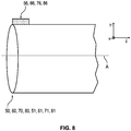
- Figs. 5A to 5C give a schematic side-view, a schematic cross-sectional side-view and a perspective and three-dimensional side-view from above, respectively, showing an embodiment of a storage container device 90 offering a storage chamber 91, 92.
- the storage container device 90 described in Figs. 5A to 5C is formed by a cylindrical tubular member forming a storage chamber 91, 92 for a respective first or second flowable component 11, 12.
- the first and second components are not indicated in these Figures.
- the storage container device 90 shows a first/second outlet passage 70, 80 with respective first/second outlet opening region 71, 81 terminating in a respective first/second outlet opening 72, 82.
- Figs. 5D and 5E elucidate in more detail the so called a snap, lock, latch, or click into place action for attaching a cartridge container device 90 having as an engaging element 97 an annular rim running on the outer periphery 74, 84.
- the corresponding inner periphery 53, 63 of head plate device 45 has as an engaging element 96 an annular recess 96 running on or within said inner periphery 53, 63.
- Engaging element 96 and 97 have complimentary shapes in order to achieve cooperation and the required snap, lock, latch, or click into place action for attaching the cartridge container device 90 to the head plate.
- Elasticity and/or a resilient nature of one or both of the cooperating engaging elements 96 and 97 might be helpful, too, for supporting their action.
- the outer periphery 74, 84 of the outlet passage 70, 80 of the storage container device 90 comprises male protruding engaging elements 76, 86 which protrude outwardly from the outer periphery 74, 84, whereas the inner periphery 73, 83 does not carry any engaging element.
- FIGs. 6 and 7A to 7D as well as 8 elucidate different aspects of the geometry, the orientation and the position of an engaging element 56, 66, 76, 86 with respect to the inner periphery 53, 63, 73, 83 or outer periphery 54, 64, 74, 84 of a first/second inlet/outlet passage 50, 60, 70, 80 and its first/second inlet/outlet opening region 51, 61, 71, 81 and its respective first/second inlet/outlet opening 52, 62, 72, 82.
- Each of the inlet and/or outlet passages 50, 60, 70, 80 has an essentially circular geometry with a symmetry axis A.
- Figs. 6 and 7A to 7D as well as 8 all apply to inlet passages 50, 60 of a head plate device 45 and to outlet passages 70, 80 of a storage container device 90.
- the provided engaging element 56, 66, 76, 86 is formed as a protrusion on the outer periphery 54, 64, 74, 84 of the respective opening region 51, 61, 71, 81.
- the protrusion protrudes from the outer periphery 54, 64, 74, 84 outwardly away from the symmetry axis A.
- the engaging element 56, 66, 76, 86 is formed as a male protrusion on the inner periphery 53, 63, 73, 83 protruding radially inwardly toward the symmetry axis A.
- female recesses are provided as engaging elements 56, 66, 76, 86, either recessing from the inner periphery 53, 63, 73, 83 radially outwardly away from the symmetry axis A and on outer periphery 54, 64, 74, 84 radially inwardly towards the symmetry axis A.
- FIG. 8 demonstrates a possible location of the engaging element 56, 66, 76, 86 in the front portion of the first and second inlet/outlet opening regions 51, 61, 71, 81 in the direction of the symmetry axis A.
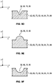
- FIGS. 9A to 9F demonstrate by means of schematic and cross-sectional side-views possible shapes of engaging elements 56, 66, 76, 86.
- Figs. 9A , C, E indicate the provision of male protruding engaging elements 56, 66, 76, 86 which have a rectangular, triangular or semi-circular cross-section and which extend from a respective periphery 53, 54, 63, 64, 73, 74, 83, 84.
- FIGs. 9B , D, F demonstrate the provision of engaging elements 56, 66,76, 86 in the form of female recesses which recess from the respective periphery 53, 54, 63, 64, 73, 74, 83, 84.
- Figs. 10A to D demonstrate by means of schematic and cross-sectional side-views how first and second inlet and outlet passage 50, 60; 70, 80 can be connected to each other.
- the outer periphery 54, 64 of an inlet passage 50, 60 of a head plate device 45 cooperates and comes into mechanic contact with the inner periphery 73, 83 of an inlet passage 70, 80 of a storage container device 90.
- FIG. 10B shows that the inner periphery 53, 63 of an inlet passage 50, 60 of a head plate device 10 cooperates with and comes into mechanic contact with a respective outer periphery 74, 84 of an outlet passage 70, 80 of a storage container device 90.
- Figs. 10C and 10D demonstrate that the outlet passage 70, 80 of a storage container device 90 or the inlet passage 50, 60 of a head plate device 10 may be formed with a recess in order to receive the rim formed by the corresponding inlet passage 50, 60 or outlet passage 70, 80, in which case both of the outer periphery 54, 64 or 74, 84 and the inner periphery 53, 63 or 73, 83 either of the inlet passage 50, 60 or the outlet passage 70, 80, respectively, may be provided with respective engaging elements 56, 66, 76, 86.
- Figs. 11A and 11B schematically demonstrate that the respective engaging elements 56, 66, 76, 86 may be positioned with a separated gap element 57, 67, 77, 87 between them as shown in Fig 11A or in direct contact with each other without having the space, separation or gap element 57, 67, 77, 87 between them as shown in Fig 11B .
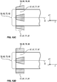
- Figs. 12A to 12D demonstrate different possible radial and circumferential extensions for the engaging elements 56, 66, 76, 86 by means of which a tapered structure or configuration is realized and a form-fit, press-fit or force-fit can be obtained.
- Fig. 12A shows the most simple case where the engaging element 56, 66, 76, 86 has in both the radial direction and the circumferential direction a constant dimension, i.e. a constant width in the circumferential direction and its constant height in the radial direction. Between the respective engaging elements 56, 66, 76, 86 a respective gap, spacing or gap element 57, 67, 77, 87 is provided.
- the width of the engaging elements 56, 66, 76, 86 in the circumferential direction is constant, whereas in the radial direction the height of the engaging element 56, 66, 76, 86 decreases in the direction towards the opening 52, 62, 72, 82.
- Fig. 12C shows a combination of the embodiments of Figs. 12B and 12D .
- the height of the engaging element 56, 66, 76, 86 in the radial direction as well as the width of the engaging element 56, 66, 76, 86 in the circumferential direction both decrease from their maximum value at the distal position from the opening 52, 62, 72, 82 to a minimum value in the direction towards the opening 52, 62, 72, 82.
- Fig. 12C or Fig. 12D provide for a self-alignment during the coupling process of the elements to be coupled due to the tapered shape provided by the non-constant width of the engagement elements. This effect is most prominent, if the respective cooperating male and female elements have corresponding tapered shapes.
Landscapes
- Engineering & Computer Science (AREA)
- Mechanical Engineering (AREA)
- Containers And Packaging Bodies Having A Special Means To Remove Contents (AREA)
- Package Specialized In Special Use (AREA)
Claims (17)
- Agencement de cartouche (100) pour un appareil de distribution (1) permettant la distribution d'au moins deux éléments fluidifiables (11, 12), comprenant :- un dispositif de plaque de tête (45) comprenant :-- au moins deux ouvertures d'évacuation distinctes (98, 99) permettant respectivement la distribution des au moins deux éléments fluidifiables (11, 12), et-- au moins deux passages d'admission distincts (50, 60) à travers lesquels les au moins deux éléments fluidifiables (11, 12) peuvent être introduits et amenés à circuler séparément l'un de l'autre vers l'une respective des ouvertures d'évacuation (98, 99),
dans lequel :-- chacun desdits passages d'admission (50, 60) du dispositif de plaque de tête (45) est conçu pour coopérer, de préférence de manière étanche, avec un passage d'évacuation (70, 80) respectif d'un dispositif de récipient de stockage (90),-- au moins l'un des passages d'admission (50, 60) du dispositif de plaque de tête (45) comprend une région d'ouverture d'admission (51, 61) à section transversale de forme sensiblement circulaire présentant au moins une périphérie interne (53, 63) et une périphérie externe (54, 64),-- au moins l'une de la périphérie interne (53, 63) et de la périphérie externe (54, 64) comprend au moins un élément d'entrée en prise (56, 66, 96), et-- l'au moins un élément d'entrée en prise (56, 66, 96) s'étend radialement depuis la périphérie interne (53, 63) ou la périphérie externe (54, 64) respective,et- au moins deux dispositifs de récipient de stockage (90) pour recevoir ou pour fournir une chambre (91, 92) respective pour un élément respectif des au moins deux éléments fluidifiables (11, 12), au moins l'un des dispositifs de récipient de stockage (90) comprenant :-- une chambre de stockage (91, 92) pour stocker un élément fluidifiable (11, 12) et-- un passage d'évacuation (70, 80) à travers lequel l'élément fluidifiable (11, 12) peut être déchargé,
dans lequel :-- le passage d'évacuation (70, 80) du dispositif de récipient de stockage (90) est conçu pour coopérer, de préférence de manière étanche, avec un passage d'admission (50, 60) respectif du dispositif de plaque de tête (45),-- le passage d'évacuation (70, 80) du dispositif de récipient de stockage (90) comprend une région d'ouverture d'évacuation (71, 81) à section transversale de forme sensiblement circulaire présentant au moins une périphérie interne (73, 83) et une périphérie externe (74, 84),-- au moins l'une de la périphérie interne (73, 83) et de la périphérie externe (74, 84) comprend au moins un élément d'entrée en prise (76, 86, 97), et-- l'au moins un élément d'entrée en prise (76, 86, 97) s'étend radialement depuis la périphérie interne (73, 83) ou la périphérie externe (74, 84) respective,- caractérisé en ce que l'au moins un élément d'entrée en prise (56, 66, 96) du dispositif de plaque de tête est configuré pour entrer en prise avec l'élément d'entrée en prise coopérant et sensiblement complémentaire (76, 86, 97) du passage d'évacuation (70, 80) correspondant du dispositif de récipient de stockage (90) dans un état où le passage d'admission (50, 60) du dispositif de plaque de tête (45), de préférence de manière étanche, coopère avec le passage d'évacuation (70, 80) respectif du dispositif de récipient de stockage (90), assurant ainsi une coopération résistant au couple entre le passage d'admission (50, 60) du dispositif de plaque de tête (45) et le passage d'évacuation (70, 80) respectif du dispositif de récipient de stockage (90) en empêchant au moins un mouvement de rotation autour d'un axe de symétrie (A) respectif sous-jacent à la section transversale de forme sensiblement circulaire de la périphérie interne (53, 63) et de la périphérie externe (54, 64) du passage d'admission (50, 60) du dispositif de plaque de tête (45). - Agencement de cartouche (100) selon la revendication 1, dans lequel l'au moins un élément d'entrée en prise (56, 66, 96) du dispositif de plaque de tête est configuré pour entrer en prise avec l'élément d'entrée en prise coopérant et sensiblement complémentaire (76, 86, 97) du passage d'évacuation (70, 80) correspondant du dispositif de récipient de stockage (90) dans un état où le passage d'admission (50, 60) du dispositif de plaque de tête (45), de préférence de manière étanche, coopère avec le passage d'évacuation (70, 80) respectif du dispositif de récipient de stockage (90), garantissant ainsi au moins l'un des points suivants :(i) un claquement, un verrouillage, un blocage ou un enclenchement,(ii) une liaison de forme,(iii) un ajustement serré, et(iv) une liaison de force.
- Agencement de cartouche (100) selon l'une quelconque des revendications précédentes, dans lequel le dispositif de plaque de tête (45) comprend des premier et second côtés opposés (45a, 45b),- dans lequel les au moins deux passages d'admission distincts (50, 60) sont formés sur l'un des premier et second côtés (45a, 45b),- dans lequel les au moins deux ouvertures d'évacuation distinctes (98, 99) sont formées sur l'autre des premier et second côtés (45b, 45a), et- dans lequel, en particulier, le nombre de passages d'admission (50, 60) est identique au nombre d'ouvertures d'évacuation (98, 99).
- Agencement de cartouche (100) selon l'une quelconque des revendications précédentes,- dans lequel une pluralité d'éléments d'entrée en prise (56, 66, 76, 86, 96, 96) est prévue,- dans lequel une première fraction de la pluralité d'éléments d'entrée en prise (56, 66, 76, 86, 96, 97) est configurée pour réaliser ladite coopération résistant au couple entre le passage d'admission (50, 60) du dispositif de plaque de tête (45) et le passage d'évacuation (70, 80) respectif du dispositif de récipient de stockage (90), et- dans lequel une seconde fraction de la pluralité d'éléments d'entrée en prise (56, 66, 76, 86, 96, 97) est configurée pour réaliser une prise entre le passage d'admission (50, 60) du dispositif de plaque de tête (45) et le passage d'évacuation (70, 80) respectif du dispositif de récipient de stockage (90), évitant ainsi un mouvement axial et une séparation spatiale par inadvertance de ceux-ci.
- Agencement de cartouche (100) selon l'une quelconque des revendications précédentes, dans lequel l'au moins un élément d'entrée en prise (56, 66, 76, 86, 96, 97) respectif est formé comme un élément mâle faisant saillie soit depuis la périphérie interne (53, 63, 73, 83) de la région d'ouverture d'admission ou d'évacuation (51, 61 ; 71, 81) respective du passage d'admission ou d'évacuation (50, 60 ; 70, 80) respectif radialement vers l'intérieur soit depuis la périphérie externe (54, 64, 74, 84) de la région d'ouverture d'admission ou d'évacuation (51, 61 ; 71, 81) respective du passage d'admission ou d'évacuation (50, 60 ; 70, 80) respectif radialement vers l'extérieur.
- Agencement de cartouche (100) selon l'une quelconque des revendications précédentes, dans lequel l'au moins un élément d'entrée en prise (56, 66, 76, 86, 96, 97) respectif est formé comme un élément femelle s'enfonçant soit depuis la périphérie interne (53, 63, 73, 83) de la région d'ouverture d'admission ou d'évacuation (51, 61 ; 71, 81) respective du passage d'admission ou d'évacuation (50, 60 ; 70, 80) respectif radialement vers l'extérieur soit depuis la périphérie externe (54, 64, 74, 84) de la région d'ouverture d'admission ou d'évacuation (51, 61 ; 71, 81) respective du passage d'admission ou d'évacuation (50, 60, 70, 80) respectif radialement vers l'intérieur.
- Agencement de cartouche (100) selon l'une quelconque des revendications précédentes, dans lequel l'au moins un élément d'entrée en prise (56, 66, 76, 86, 96, 97) respectif est formé comme ou comprend au moins l'un des éléments suivants :(A) un élément à ailettes s'étendant axialement et/ou circonférentiellement par rapport à la région d'ouverture d'admission ou d'évacuation (51, 61 ; 71, 81) respective,(B) une fente s'étendant axialement et/ou circonférentiellement par rapport à la région d'ouverture d'admission ou d'évacuation (51, 61 ; 71, 81) respective,(C) un élément ayant une section transversale polygonale, rectangulaire, triangulaire, semi-circulaire ou ovale dans la direction axiale, chacune sur la périphérie respective (53, 63, 54, 64) et s'étendant axialement et/ou circonférentiellement par rapport à la région d'ouverture d'admission ou d'évacuation (51, 61 ; 71, 81) respective,(D) un élément élastique et/ou solide s'étendant axialement et/ou circonférentiellement par rapport à la région d'ouverture d'admission ou d'évacuation (51, 61 ; 71, 81) respective,(E) un élément élastique s'étendant axialement et/ou circonférentiellement et configuré pour un mouvement élastique dans une direction radiale perpendiculaire à une direction axiale et/ou à une direction circonférentielle par rapport à la région d'ouverture d'admission ou d'évacuation (51, 61 ; 71, 81) respective.
- Agencement de cartouche (100) selon l'une quelconque des revendications précédentes, dans lequel une pluralité d'éléments d'entrée en prise (56, 66, 76, 86, 96, 97) est prévue sur au moins l'une de la périphérie interne (53, 63, 73, 83) et de la périphérie externe (54, 64, 74, 84) d'au moins l'une des régions d'ouverture d'admission ou d'évacuation (51, 61, 71, 81) d'au moins l'un des passages d'admission et d'évacuation (50, 60).
- Agencement de cartouche (100) Dispositif (45, 90) selon la revendication 8, dans lequel chacun de la pluralité d'éléments d'entrée en prise (56, 66, 76, 86, 96, 97) est formé avec une forme sensiblement identique.
- Agencement de cartouche (100) selon la revendication 8 ou 9, dans lequel la pluralité d'éléments d'entrée en prise (56, 66, 76, 86, 96, 97) sur une périphérie (53, 54, 63, 64, 73, 74, 83, 84) respective est une séquence de structures mâles et femelles alternées.
- Agencement de cartouche (100) selon la revendication 8 à 10, dans lequel des éléments individuels de paires d'éléments d'entrée en prise adjacents (56, 66, 76, 86, 96, 97) de la pluralité d'éléments d'entrée en prise (56, 66, 76, 86, 96, 97) sur une périphérie (53, 54, 63, 64, 73, 74, 83, 84) respective sont positionnés directement adjacents et en contact direct les uns avec les autres.
- Agencement de cartouche (100) selon la revendication 8 à 11, dans lequel des éléments individuels de paires d'éléments d'entrée en prise adjacents (56, 66, 76, 86, 96, 97) de la pluralité d'éléments d'entrée en prise (56, 66, 76, 86) sur une périphérie (53, 54, 63, 64, 73, 74, 83, 84) respective sont positionnés sur une périphérie (53, 54, 63, 64, 73, 74, 83, 84) respective avec un élément d'espacement (57, 67, 77, 87) entre eux formé par une partie libre de la périphérie (53, 54, 63, 64, 73, 74, 83, 84) respective.
- Agencement de cartouche (100) selon l'une quelconque des revendications précédentes, dans lequel l'au moins un élément d'entrée en prise (56, 66, 76, 86, 96, 97) respectif sur une périphérie (53, 54, 63, 64, 73, 74, 83, 84) respective a une forme conçue pour réaliser une liaison de forme, un ajustement serré ou une liaison de force, de préférence - dans le cas d'un élément mâle - en ayant une forme conique avec au moins l'une d'une hauteur réduite dans la direction radiale et d'une largeur réduite dans la direction circonférentielle chacune vers l'ouverture d'admission ou d'évacuation (52, 62 ; 72, 82) respective et - dans le cas d'un élément femelle - en ayant une forme conique avec au moins l'une d'une profondeur accrue dans la direction radiale et d'une largeur accrue dans la direction circonférentielle, chacune vers l'ouverture d'admission ou d'évacuation (52, 62 ; 72, 82) respective.
- Agencement de cartouche (100) Dispositif (10, 90) selon l'une quelconque des revendications précédentes, dans lequel l'au moins un élément d'entrée en prise (56, 66, 76, 86, 96, 97) respectif est configuré pour permettre un codage mécanique par sa forme, sa position et/ou son orientation sur la périphérie respective (53, 54, 63, 64, 73, 74, 83, 84).
- Agencement de cartouche (100) selon l'une quelconque des revendications précédentes, dans lequel chacun des au moins deux dispositifs de récipient de stockage (90) est rempli de matériau d'un des au moins deux éléments fluidifiables (11, 12).
- Appareil de distribution (1) destiné à distribuer au moins deux éléments fluidifiables (11, 12), comprenant :- un dispositif de cartouche (100) selon l'une quelconque des revendications précédentes et- un dispositif mélangeur (10),dans lequel le dispositif mélangeur (10) peut être attaché ou est attaché à l'agencement de cartouche (100) et est configuré pour recevoir de l'agencement de cartouche (100) les au moins deux éléments fluidifiables (11, 12), pour mélanger les au moins deux éléments fluidifiables (11, 12), et pour les distribuer dans un état mélangé.
- Utilisation de l'agencement de cartouche (100) selon l'une quelconque des revendications 1 à 15, et/ou de l'appareil de distribution (1) selon la revendication 16 pour stocker, mélanger et/ou distribuer au moins deux éléments fluidifiables (11, 12), en particulier au moins l'un d'un produit d'étanchéité et d'un adhésif et/ou pour au moins l'une de l'installation, de la fixation, du collage, de l'étanchéification et de la réparation d'une fenêtre, en particulier d'un pare-brise ou d'un un paravent d'un véhicule, en particulier d'une voiture.
Applications Claiming Priority (2)
| Application Number | Priority Date | Filing Date | Title |
|---|---|---|---|
| EP14185972 | 2014-09-23 | ||
| PCT/EP2015/071511 WO2016046098A1 (fr) | 2014-09-23 | 2015-09-18 | Dispositif de plaque de tête, dispositif de récipient de stockage, agencement de cartouche, appareil de distribution et leur utilisation |
Publications (2)
| Publication Number | Publication Date |
|---|---|
| EP3197607A1 EP3197607A1 (fr) | 2017-08-02 |
| EP3197607B1 true EP3197607B1 (fr) | 2021-10-20 |
Family
ID=51609968
Family Applications (1)
| Application Number | Title | Priority Date | Filing Date |
|---|---|---|---|
| EP15763637.4A Active EP3197607B1 (fr) | 2014-09-23 | 2015-09-18 | Plaque distributrice, dispositif de stockage, agencement de cartouche, appareil de distribution et leur utilisation |
Country Status (5)
| Country | Link |
|---|---|
| US (1) | US10562064B2 (fr) |
| EP (1) | EP3197607B1 (fr) |
| CN (1) | CN107107093A (fr) |
| ES (1) | ES2902002T3 (fr) |
| WO (1) | WO2016046098A1 (fr) |
Families Citing this family (4)
| Publication number | Priority date | Publication date | Assignee | Title |
|---|---|---|---|---|
| EP3263483A1 (fr) * | 2016-07-01 | 2018-01-03 | Sulzer Mixpac AG | Cartouche, noyau, moule et procédé de fabrication d'une cartouche |
| CN113165007A (zh) * | 2018-07-16 | 2021-07-23 | 塞姆产品股份有限公司 | 组合物涂抹器尖端和仪器 |
| EP3632575A1 (fr) * | 2018-10-02 | 2020-04-08 | Sulzer Mixpac AG | Piston de cartouche réutilisable |
| EP4186814A1 (fr) * | 2021-11-30 | 2023-05-31 | Hilti Aktiengesellschaft | Cartouche pour un dispositif d'extrusion |
Family Cites Families (58)
| Publication number | Priority date | Publication date | Assignee | Title |
|---|---|---|---|---|
| US3390814A (en) * | 1965-09-24 | 1968-07-02 | Chem Dev Corp | Mixing device |
| US3323682A (en) * | 1965-10-06 | 1967-06-06 | Chem Dev Corp | Disposable cartridge for gun-type dispensers |
| DE3705741A1 (de) * | 1987-02-23 | 1988-09-01 | Hilti Ag | Abgabevorrichtung fuer fliessfaehige massen |
| EP0294672B1 (fr) * | 1987-06-10 | 1992-08-12 | Wilhelm A. Keller | Cartouche double pour mélange à deux composants |
| US5161715A (en) * | 1991-03-25 | 1992-11-10 | Giannuzzi Anthony C | Double-barreled epoxy injection gun |
| DK68991D0 (da) * | 1991-04-17 | 1991-04-17 | Novo Nordisk As | Manifold |
| AU1812392A (en) * | 1991-07-12 | 1993-01-14 | Minnesota Mining And Manufacturing Company | Bottle keying system |
| SK94894A3 (en) * | 1992-02-14 | 1995-06-07 | Hugo Nilsson | Closed packing |
| EP0600138B1 (fr) * | 1992-11-30 | 1997-04-16 | Wilhelm A. Keller | Cartouche avec au moins un cylindre de stockage et un mélangeur |
| GB9401439D0 (en) | 1994-01-26 | 1994-03-23 | Ciba Geigy Ag | Apparatus |
| DE19500782A1 (de) * | 1995-01-13 | 1996-07-18 | Bayer Ag | Vorrichtung zum Mischen und Ausbringen einer Formmasse |
| DE29501255U1 (de) * | 1995-01-27 | 1995-03-09 | Hilti Ag, Schaan | Folienbeutelpackung mit Folienbeutel und Bodenteil |
| US5918772A (en) * | 1995-03-13 | 1999-07-06 | Wilhelm A. Keller | Bayonet fastening device for the attachment of an accessory to a multiple component cartridge or dispensing device |
| US5530531A (en) * | 1995-03-15 | 1996-06-25 | Hewlett-Packard Company | Multiple cartridge keying apparatus |
| DE29603416U1 (de) | 1996-02-24 | 1996-04-18 | Upat GmbH & Co., 79312 Emmendingen | Kartusche für Zweikomponentenmassen |
| US5819988A (en) * | 1997-04-01 | 1998-10-13 | Sawhney; Ravi K. | Double-barreled syringe with detachable locking mixing tip |
| US6065645A (en) * | 1997-04-01 | 2000-05-23 | Discus Dental Impressions, Inc. | Double-barreled syringe with detachable locking mixing tip |
| DE29818499U1 (de) * | 1998-10-16 | 2000-03-02 | Espe Dental Ag | Mischer für Mehrkomponentenpasten |
| DE29819661U1 (de) * | 1998-11-04 | 1999-02-25 | Kress-Elektrik GmbH & Co Elektromotorenfabrik, 72406 Bisingen | Vorrichtung zum Auspressen und dosierten Abgeben von fließfähigen Mehrkomponenten |
| WO2000061457A1 (fr) * | 1999-04-12 | 2000-10-19 | Kettenbach Gmbh & Co. Kg | Feuille d'emballage pour substance pateuse |
| DE50005652D1 (de) * | 1999-07-02 | 2004-04-22 | Kettenbach Gmbh & Co Kg A | Folienverpackung für eine pastöse Substanz |
| EP1083005A3 (fr) * | 1999-08-11 | 2004-12-15 | Tah Industries, Inc. | Buse de mélange pour mélanger statique et configuration de la zone de liaison d'accesoires |
| US6443612B1 (en) * | 1999-12-02 | 2002-09-03 | Wilhelm A. Keller | Dynamic mixer |
| DE10019893C2 (de) * | 2000-04-20 | 2003-05-28 | 3M Espe Ag | Vorrichtung in Form eines dynamischen Mischers oder einer Kartuschenfront und deren Verwendung |
| EP1186554B1 (fr) * | 2000-09-05 | 2004-08-18 | Steinel GmbH & Co. KG | Cartouche de distribution de colle |
| GB2390086A (en) | 2002-06-10 | 2003-12-31 | Montgomery Daniel & Son Ltd | Tamper evident anti-refill closure |
| CA2517014C (fr) * | 2003-03-06 | 2012-07-17 | Dentsply International Inc. | Extremite de distribution et de melange |
| CA2466825C (fr) * | 2003-05-30 | 2011-04-19 | Hilti Aktiengesellschaft | Attache rapide |
| JP4323486B2 (ja) * | 2003-06-09 | 2009-09-02 | ティーエイエイチ インダストリーズ インコーポレイテッド | 2液カートリッジアセンブリー |
| WO2006005213A1 (fr) * | 2004-07-08 | 2006-01-19 | Mixpac Systems Ag | Dispositif de decharge a usage unique |
| ATE507009T1 (de) * | 2005-12-29 | 2011-05-15 | Sulzer Mixpac Ag | Abgabevorrichtung für den einmaligen gebrauch |
| CN101023905A (zh) | 2006-02-20 | 2007-08-29 | 陈庆昌 | 区分容器内装物使用对象的装置及区分方法 |
| EP1989004B1 (fr) * | 2006-03-01 | 2019-04-03 | Sulzer Mixpac AG | Seringue double en deux parties |
| FR2901255B1 (fr) * | 2006-05-16 | 2010-12-10 | Lindal France | Valve a deux voies |
| DE102007000066A1 (de) * | 2007-02-01 | 2008-09-18 | Hilti Aktiengesellschaft | Gebinde mit einer Beutelpackung und einem Kopfteil |
| DE102007007474B3 (de) | 2007-02-15 | 2008-02-28 | Bernd Hansen | Behältnis |
| DE102007000802A1 (de) * | 2007-10-01 | 2009-04-02 | Hilti Aktiengesellschaft | Foliengebinde mit nebeneinander angeordneten Folienbeutelkammern |
| DE102008001658A1 (de) * | 2008-05-08 | 2009-11-12 | Hilti Aktiengesellschaft | Foliengebinde mit nebeneinander angeordneten Folienbeuteln |
| DE102008040738A1 (de) * | 2008-07-25 | 2010-01-28 | Hilti Aktiengesellschaft | Foliengebinde |
| CH699398A1 (de) * | 2008-08-22 | 2010-02-26 | Medmix Systems Ag | Anschlussstück für Austragvorrichtung. |
| EP2328483B1 (fr) * | 2008-09-22 | 2017-01-11 | Medmix Systems AG | Raccord doté d'un élément de mélange pour système d'extraction |
| CN102665803A (zh) * | 2009-09-22 | 2012-09-12 | 药物混合系统股份公司 | 具有可移动活塞的密封容器 |
| CN201506523U (zh) | 2009-09-30 | 2010-06-16 | 中山市美捷时喷雾阀有限公司 | 一种锁瓶盖与瓶体的连接结构 |
| CH703164A1 (de) * | 2010-05-17 | 2011-11-30 | Medmix Systems Ag | Versiegelter Glasbehälter mit verschiebbarem Kolben. |
| CH703427A1 (de) * | 2010-07-12 | 2012-01-13 | Medmix Systems Ag | Kartuschendispenser mit Drehverriegelung. |
| EP2468416A1 (fr) * | 2010-12-24 | 2012-06-27 | Sika Technology AG | Dispositif d'application pour matières à plusieurs composants, ensemble de cartouche et unité d'emballage |
| CN102069945B (zh) | 2010-12-28 | 2012-12-19 | 深圳市金冠防伪科技有限公司 | 一种瓶盖的防伪方法、瓶盖及包括该瓶盖的包装容器瓶 |
| ES2503618T3 (es) * | 2011-05-02 | 2014-10-07 | Sulzer Mixpac Ag | Mezclador para mezclar al menos dos componentes fluidos así como dispositivo de descarga |
| WO2013078036A1 (fr) * | 2011-11-22 | 2013-05-30 | 3M Innovative Properties Company | Article et procédé de fermeture d'un récipient pliable |
| WO2013171030A1 (fr) * | 2012-05-14 | 2013-11-21 | Sulzer Mixpac Ag | Mélangeur à pulvérisation permettant de mélanger et de pulvériser deux composants fluides |
| US9289797B2 (en) * | 2012-11-06 | 2016-03-22 | Nordson Corporation | Dispensing assembly and method for assembling a dispenser and dispensing a fluid |
| EP2781253A1 (fr) * | 2013-03-20 | 2014-09-24 | Sulzer Mixpac AG | Pièce intermédiaire destinée à relier un élément d'extraction à un réservoir |
| EP2959861A1 (fr) * | 2014-06-23 | 2015-12-30 | Sulzer Mixpac AG | Seringues d'administration de produit multi-composant |
| US20170274414A1 (en) * | 2014-09-02 | 2017-09-28 | Sika Technology Ag | Application device for applying gel-like and/or paste-like compositions and application unit for an application device of this type |
| CN106714981A (zh) * | 2014-09-23 | 2017-05-24 | Sika技术股份公司 | 用于材料的施加装置 |
| CA161645S (en) * | 2014-09-23 | 2017-05-03 | Sika Tech Ag | Combined adapter with containers, a cartridge and a sausage foil pack |
| US20170297049A1 (en) * | 2014-09-23 | 2017-10-19 | Sika Technology Ag | Application device for multicomponent materials |
| EP3162433B1 (fr) * | 2015-10-30 | 2022-11-30 | medmix Switzerland AG | Melangeur statique |
-
2015
- 2015-09-18 EP EP15763637.4A patent/EP3197607B1/fr active Active
- 2015-09-18 WO PCT/EP2015/071511 patent/WO2016046098A1/fr not_active Ceased
- 2015-09-18 ES ES15763637T patent/ES2902002T3/es active Active
- 2015-09-18 US US15/513,807 patent/US10562064B2/en active Active
- 2015-09-18 CN CN201580051260.4A patent/CN107107093A/zh active Pending
Non-Patent Citations (1)
| Title |
|---|
| None * |
Also Published As
| Publication number | Publication date |
|---|---|
| EP3197607A1 (fr) | 2017-08-02 |
| WO2016046098A1 (fr) | 2016-03-31 |
| US10562064B2 (en) | 2020-02-18 |
| ES2902002T3 (es) | 2022-03-24 |
| CN107107093A (zh) | 2017-08-29 |
| US20180229260A1 (en) | 2018-08-16 |
Similar Documents
| Publication | Publication Date | Title |
|---|---|---|
| EP3197607B1 (fr) | Plaque distributrice, dispositif de stockage, agencement de cartouche, appareil de distribution et leur utilisation | |
| CN108463291B (zh) | 用于将分离式出口流体筒连接到单入口混合器的适配器和相关方法 | |
| US8286832B2 (en) | Dispensing device for single use | |
| CA2681178C (fr) | Ensemble de distribution equipe d'accessoires fixes amovibles | |
| EP3160380B1 (fr) | Seringues d'administration de produit multi-composant | |
| EP2200492B1 (fr) | Distributeur de liquide ménager pourvu d'un bec verseur à clé et recharge | |
| US20080083782A1 (en) | Multicomponent cartridge | |
| JP7033087B2 (ja) | 単一入口ミキサに分離出口流体カートリッジを接続するためのアダプタ、及び、その関連方法 | |
| EP2727655B1 (fr) | Ensemble de distribution et procédé utilisant un verrouillage par encliquetage entre un mélangeur et une cartouche | |
| US8033429B2 (en) | Dispensing device for single use | |
| RU2582397C2 (ru) | Миксер для смешивания по меньшей мере двух текучих компонентов и выдачное устройство | |
| US9550159B2 (en) | Mixer and dispensing device | |
| JP4236111B2 (ja) | 多室コンテナ・アセンブリ・システム | |
| EP2563524A1 (fr) | Appareil de mélange et de distribution de plusieurs composants pouvant s'écouler | |
| EP3283389B1 (fr) | Système de cartouche de fluide et procédé d'utilisation d'un système de cartouche de fluide | |
| JP3769058B2 (ja) | ミキサと多反応性成分分配装置との組立体及び整合結合方法 | |
| TW201313172A (zh) | 模組式泵 | |
| WO2006031480A2 (fr) | Cartouche a deux fluides concue pour stocker et distribuer des fluides dans des rapports inegaux | |
| WO2012011162A1 (fr) | Dispositif d'aérosol pour distribution d'une pluralité de liquides | |
| JP2020189693A (ja) | スポイト型異種内容物混合容器 | |
| CN114845816A (zh) | 用于制剂筒的阀系统 | |
| US20090277926A1 (en) | Foil container with foil bags arranged next to one another | |
| US8042926B2 (en) | Cartridge for an ejectable compound | |
| CN210417573U (zh) | 泵送式分配容器 | |
| EP1657183A2 (fr) | Moyen de rétention pour pistons |
Legal Events
| Date | Code | Title | Description |
|---|---|---|---|
| STAA | Information on the status of an ep patent application or granted ep patent |
Free format text: STATUS: THE INTERNATIONAL PUBLICATION HAS BEEN MADE |
|
| PUAI | Public reference made under article 153(3) epc to a published international application that has entered the european phase |
Free format text: ORIGINAL CODE: 0009012 |
|
| STAA | Information on the status of an ep patent application or granted ep patent |
Free format text: STATUS: REQUEST FOR EXAMINATION WAS MADE |
|
| 17P | Request for examination filed |
Effective date: 20170424 |
|
| AK | Designated contracting states |
Kind code of ref document: A1 Designated state(s): AL AT BE BG CH CY CZ DE DK EE ES FI FR GB GR HR HU IE IS IT LI LT LU LV MC MK MT NL NO PL PT RO RS SE SI SK SM TR |
|
| AX | Request for extension of the european patent |
Extension state: BA ME |
|
| DAV | Request for validation of the european patent (deleted) | ||
| DAX | Request for extension of the european patent (deleted) | ||
| STAA | Information on the status of an ep patent application or granted ep patent |
Free format text: STATUS: EXAMINATION IS IN PROGRESS |
|
| 17Q | First examination report despatched |
Effective date: 20200827 |
|
| GRAP | Despatch of communication of intention to grant a patent |
Free format text: ORIGINAL CODE: EPIDOSNIGR1 |
|
| STAA | Information on the status of an ep patent application or granted ep patent |
Free format text: STATUS: GRANT OF PATENT IS INTENDED |
|
| INTG | Intention to grant announced |
Effective date: 20210602 |
|
| GRAS | Grant fee paid |
Free format text: ORIGINAL CODE: EPIDOSNIGR3 |
|
| GRAA | (expected) grant |
Free format text: ORIGINAL CODE: 0009210 |
|
| STAA | Information on the status of an ep patent application or granted ep patent |
Free format text: STATUS: THE PATENT HAS BEEN GRANTED |
|
| AK | Designated contracting states |
Kind code of ref document: B1 Designated state(s): AL AT BE BG CH CY CZ DE DK EE ES FI FR GB GR HR HU IE IS IT LI LT LU LV MC MK MT NL NO PL PT RO RS SE SI SK SM TR |
|
| REG | Reference to a national code |
Ref country code: GB Ref legal event code: FG4D |
|
| REG | Reference to a national code |
Ref country code: CH Ref legal event code: EP |
|
| REG | Reference to a national code |
Ref country code: IE Ref legal event code: FG4D |
|
| REG | Reference to a national code |
Ref country code: DE Ref legal event code: R096 Ref document number: 602015074285 Country of ref document: DE |
|
| REG | Reference to a national code |
Ref country code: AT Ref legal event code: REF Ref document number: 1439478 Country of ref document: AT Kind code of ref document: T Effective date: 20211115 |
|
| REG | Reference to a national code |
Ref country code: LT Ref legal event code: MG9D |
|
| REG | Reference to a national code |
Ref country code: NL Ref legal event code: MP Effective date: 20211020 |
|
| REG | Reference to a national code |
Ref country code: AT Ref legal event code: MK05 Ref document number: 1439478 Country of ref document: AT Kind code of ref document: T Effective date: 20211020 |
|
| REG | Reference to a national code |
Ref country code: ES Ref legal event code: FG2A Ref document number: 2902002 Country of ref document: ES Kind code of ref document: T3 Effective date: 20220324 |
|
| PG25 | Lapsed in a contracting state [announced via postgrant information from national office to epo] |
Ref country code: RS Free format text: LAPSE BECAUSE OF FAILURE TO SUBMIT A TRANSLATION OF THE DESCRIPTION OR TO PAY THE FEE WITHIN THE PRESCRIBED TIME-LIMIT Effective date: 20211020 Ref country code: LT Free format text: LAPSE BECAUSE OF FAILURE TO SUBMIT A TRANSLATION OF THE DESCRIPTION OR TO PAY THE FEE WITHIN THE PRESCRIBED TIME-LIMIT Effective date: 20211020 Ref country code: FI Free format text: LAPSE BECAUSE OF FAILURE TO SUBMIT A TRANSLATION OF THE DESCRIPTION OR TO PAY THE FEE WITHIN THE PRESCRIBED TIME-LIMIT Effective date: 20211020 Ref country code: BG Free format text: LAPSE BECAUSE OF FAILURE TO SUBMIT A TRANSLATION OF THE DESCRIPTION OR TO PAY THE FEE WITHIN THE PRESCRIBED TIME-LIMIT Effective date: 20220120 Ref country code: AT Free format text: LAPSE BECAUSE OF FAILURE TO SUBMIT A TRANSLATION OF THE DESCRIPTION OR TO PAY THE FEE WITHIN THE PRESCRIBED TIME-LIMIT Effective date: 20211020 |
|
| PG25 | Lapsed in a contracting state [announced via postgrant information from national office to epo] |
Ref country code: IS Free format text: LAPSE BECAUSE OF FAILURE TO SUBMIT A TRANSLATION OF THE DESCRIPTION OR TO PAY THE FEE WITHIN THE PRESCRIBED TIME-LIMIT Effective date: 20220220 Ref country code: SE Free format text: LAPSE BECAUSE OF FAILURE TO SUBMIT A TRANSLATION OF THE DESCRIPTION OR TO PAY THE FEE WITHIN THE PRESCRIBED TIME-LIMIT Effective date: 20211020 Ref country code: PT Free format text: LAPSE BECAUSE OF FAILURE TO SUBMIT A TRANSLATION OF THE DESCRIPTION OR TO PAY THE FEE WITHIN THE PRESCRIBED TIME-LIMIT Effective date: 20220221 Ref country code: PL Free format text: LAPSE BECAUSE OF FAILURE TO SUBMIT A TRANSLATION OF THE DESCRIPTION OR TO PAY THE FEE WITHIN THE PRESCRIBED TIME-LIMIT Effective date: 20211020 Ref country code: NO Free format text: LAPSE BECAUSE OF FAILURE TO SUBMIT A TRANSLATION OF THE DESCRIPTION OR TO PAY THE FEE WITHIN THE PRESCRIBED TIME-LIMIT Effective date: 20220120 Ref country code: NL Free format text: LAPSE BECAUSE OF FAILURE TO SUBMIT A TRANSLATION OF THE DESCRIPTION OR TO PAY THE FEE WITHIN THE PRESCRIBED TIME-LIMIT Effective date: 20211020 Ref country code: LV Free format text: LAPSE BECAUSE OF FAILURE TO SUBMIT A TRANSLATION OF THE DESCRIPTION OR TO PAY THE FEE WITHIN THE PRESCRIBED TIME-LIMIT Effective date: 20211020 Ref country code: HR Free format text: LAPSE BECAUSE OF FAILURE TO SUBMIT A TRANSLATION OF THE DESCRIPTION OR TO PAY THE FEE WITHIN THE PRESCRIBED TIME-LIMIT Effective date: 20211020 Ref country code: GR Free format text: LAPSE BECAUSE OF FAILURE TO SUBMIT A TRANSLATION OF THE DESCRIPTION OR TO PAY THE FEE WITHIN THE PRESCRIBED TIME-LIMIT Effective date: 20220121 |
|
| REG | Reference to a national code |
Ref country code: DE Ref legal event code: R097 Ref document number: 602015074285 Country of ref document: DE |
|
| PG25 | Lapsed in a contracting state [announced via postgrant information from national office to epo] |
Ref country code: SM Free format text: LAPSE BECAUSE OF FAILURE TO SUBMIT A TRANSLATION OF THE DESCRIPTION OR TO PAY THE FEE WITHIN THE PRESCRIBED TIME-LIMIT Effective date: 20211020 Ref country code: SK Free format text: LAPSE BECAUSE OF FAILURE TO SUBMIT A TRANSLATION OF THE DESCRIPTION OR TO PAY THE FEE WITHIN THE PRESCRIBED TIME-LIMIT Effective date: 20211020 Ref country code: RO Free format text: LAPSE BECAUSE OF FAILURE TO SUBMIT A TRANSLATION OF THE DESCRIPTION OR TO PAY THE FEE WITHIN THE PRESCRIBED TIME-LIMIT Effective date: 20211020 Ref country code: EE Free format text: LAPSE BECAUSE OF FAILURE TO SUBMIT A TRANSLATION OF THE DESCRIPTION OR TO PAY THE FEE WITHIN THE PRESCRIBED TIME-LIMIT Effective date: 20211020 Ref country code: DK Free format text: LAPSE BECAUSE OF FAILURE TO SUBMIT A TRANSLATION OF THE DESCRIPTION OR TO PAY THE FEE WITHIN THE PRESCRIBED TIME-LIMIT Effective date: 20211020 Ref country code: CZ Free format text: LAPSE BECAUSE OF FAILURE TO SUBMIT A TRANSLATION OF THE DESCRIPTION OR TO PAY THE FEE WITHIN THE PRESCRIBED TIME-LIMIT Effective date: 20211020 |
|
| PLBE | No opposition filed within time limit |
Free format text: ORIGINAL CODE: 0009261 |
|
| STAA | Information on the status of an ep patent application or granted ep patent |
Free format text: STATUS: NO OPPOSITION FILED WITHIN TIME LIMIT |
|
| 26N | No opposition filed |
Effective date: 20220721 |
|
| PG25 | Lapsed in a contracting state [announced via postgrant information from national office to epo] |
Ref country code: AL Free format text: LAPSE BECAUSE OF FAILURE TO SUBMIT A TRANSLATION OF THE DESCRIPTION OR TO PAY THE FEE WITHIN THE PRESCRIBED TIME-LIMIT Effective date: 20211020 |
|
| PG25 | Lapsed in a contracting state [announced via postgrant information from national office to epo] |
Ref country code: SI Free format text: LAPSE BECAUSE OF FAILURE TO SUBMIT A TRANSLATION OF THE DESCRIPTION OR TO PAY THE FEE WITHIN THE PRESCRIBED TIME-LIMIT Effective date: 20211020 |
|
| PG25 | Lapsed in a contracting state [announced via postgrant information from national office to epo] |
Ref country code: MC Free format text: LAPSE BECAUSE OF FAILURE TO SUBMIT A TRANSLATION OF THE DESCRIPTION OR TO PAY THE FEE WITHIN THE PRESCRIBED TIME-LIMIT Effective date: 20211020 |
|
| REG | Reference to a national code |
Ref country code: CH Ref legal event code: PL |
|
| REG | Reference to a national code |
Ref country code: BE Ref legal event code: MM Effective date: 20220930 |
|
| PG25 | Lapsed in a contracting state [announced via postgrant information from national office to epo] |
Ref country code: LU Free format text: LAPSE BECAUSE OF NON-PAYMENT OF DUE FEES Effective date: 20220918 |
|
| PG25 | Lapsed in a contracting state [announced via postgrant information from national office to epo] |
Ref country code: LI Free format text: LAPSE BECAUSE OF NON-PAYMENT OF DUE FEES Effective date: 20220930 Ref country code: IE Free format text: LAPSE BECAUSE OF NON-PAYMENT OF DUE FEES Effective date: 20220918 Ref country code: CH Free format text: LAPSE BECAUSE OF NON-PAYMENT OF DUE FEES Effective date: 20220930 |
|
| PG25 | Lapsed in a contracting state [announced via postgrant information from national office to epo] |
Ref country code: BE Free format text: LAPSE BECAUSE OF NON-PAYMENT OF DUE FEES Effective date: 20220930 |
|
| PG25 | Lapsed in a contracting state [announced via postgrant information from national office to epo] |
Ref country code: HU Free format text: LAPSE BECAUSE OF FAILURE TO SUBMIT A TRANSLATION OF THE DESCRIPTION OR TO PAY THE FEE WITHIN THE PRESCRIBED TIME-LIMIT; INVALID AB INITIO Effective date: 20150918 |
|
| PG25 | Lapsed in a contracting state [announced via postgrant information from national office to epo] |
Ref country code: CY Free format text: LAPSE BECAUSE OF FAILURE TO SUBMIT A TRANSLATION OF THE DESCRIPTION OR TO PAY THE FEE WITHIN THE PRESCRIBED TIME-LIMIT Effective date: 20211020 |
|
| PG25 | Lapsed in a contracting state [announced via postgrant information from national office to epo] |
Ref country code: MK Free format text: LAPSE BECAUSE OF FAILURE TO SUBMIT A TRANSLATION OF THE DESCRIPTION OR TO PAY THE FEE WITHIN THE PRESCRIBED TIME-LIMIT Effective date: 20211020 |
|
| PG25 | Lapsed in a contracting state [announced via postgrant information from national office to epo] |
Ref country code: MT Free format text: LAPSE BECAUSE OF FAILURE TO SUBMIT A TRANSLATION OF THE DESCRIPTION OR TO PAY THE FEE WITHIN THE PRESCRIBED TIME-LIMIT Effective date: 20211020 |
|
| PGFP | Annual fee paid to national office [announced via postgrant information from national office to epo] |
Ref country code: DE Payment date: 20250820 Year of fee payment: 11 |
|
| PGFP | Annual fee paid to national office [announced via postgrant information from national office to epo] |
Ref country code: IT Payment date: 20250820 Year of fee payment: 11 |
|
| PGFP | Annual fee paid to national office [announced via postgrant information from national office to epo] |
Ref country code: GB Payment date: 20250820 Year of fee payment: 11 |
|
| PGFP | Annual fee paid to national office [announced via postgrant information from national office to epo] |
Ref country code: FR Payment date: 20250821 Year of fee payment: 11 |
|
| PG25 | Lapsed in a contracting state [announced via postgrant information from national office to epo] |
Ref country code: TR Free format text: LAPSE BECAUSE OF FAILURE TO SUBMIT A TRANSLATION OF THE DESCRIPTION OR TO PAY THE FEE WITHIN THE PRESCRIBED TIME-LIMIT Effective date: 20211020 |
|
| PGFP | Annual fee paid to national office [announced via postgrant information from national office to epo] |
Ref country code: ES Payment date: 20251001 Year of fee payment: 11 |