EP3208428A1 - Systeme d'etancheification en matiere composite en fibres a ceramique - Google Patents
Systeme d'etancheification en matiere composite en fibres a ceramique Download PDFInfo
- Publication number
- EP3208428A1 EP3208428A1 EP16156681.5A EP16156681A EP3208428A1 EP 3208428 A1 EP3208428 A1 EP 3208428A1 EP 16156681 A EP16156681 A EP 16156681A EP 3208428 A1 EP3208428 A1 EP 3208428A1
- Authority
- EP
- European Patent Office
- Prior art keywords
- component
- sealing
- wall
- recess
- elements
- Prior art date
- Legal status (The legal status is an assumption and is not a legal conclusion. Google has not performed a legal analysis and makes no representation as to the accuracy of the status listed.)
- Granted
Links
- 238000007789 sealing Methods 0.000 title claims abstract description 77
- 239000000835 fiber Substances 0.000 title claims abstract description 33
- 239000000919 ceramic Substances 0.000 title claims abstract description 25
- 239000002131 composite material Substances 0.000 title claims abstract description 15
- 239000004744 fabric Substances 0.000 claims abstract description 10
- 229910010293 ceramic material Inorganic materials 0.000 claims abstract description 3
- 238000005253 cladding Methods 0.000 claims description 39
- 238000005520 cutting process Methods 0.000 claims description 2
- 239000007789 gas Substances 0.000 description 23
- 239000002184 metal Substances 0.000 description 5
- 239000003795 chemical substances by application Substances 0.000 description 4
- 238000010276 construction Methods 0.000 description 3
- 239000011324 bead Substances 0.000 description 2
- 230000005540 biological transmission Effects 0.000 description 2
- 238000007667 floating Methods 0.000 description 2
- 239000008187 granular material Substances 0.000 description 2
- 238000004519 manufacturing process Methods 0.000 description 2
- 230000004308 accommodation Effects 0.000 description 1
- 230000008878 coupling Effects 0.000 description 1
- 238000010168 coupling process Methods 0.000 description 1
- 238000005859 coupling reaction Methods 0.000 description 1
- 238000006073 displacement reaction Methods 0.000 description 1
- 230000000694 effects Effects 0.000 description 1
- 238000005516 engineering process Methods 0.000 description 1
- 230000005484 gravity Effects 0.000 description 1
- 239000000463 material Substances 0.000 description 1
- 238000011089 mechanical engineering Methods 0.000 description 1
- 239000007769 metal material Substances 0.000 description 1
- 238000000034 method Methods 0.000 description 1
- 230000003014 reinforcing effect Effects 0.000 description 1
- 229920006395 saturated elastomer Polymers 0.000 description 1
- 239000000565 sealant Substances 0.000 description 1
- 238000004513 sizing Methods 0.000 description 1
- 230000000087 stabilizing effect Effects 0.000 description 1
- 238000003860 storage Methods 0.000 description 1
- 230000007704 transition Effects 0.000 description 1
Images


Classifications
-
- F—MECHANICAL ENGINEERING; LIGHTING; HEATING; WEAPONS; BLASTING
- F01—MACHINES OR ENGINES IN GENERAL; ENGINE PLANTS IN GENERAL; STEAM ENGINES
- F01D—NON-POSITIVE DISPLACEMENT MACHINES OR ENGINES, e.g. STEAM TURBINES
- F01D11/00—Preventing or minimising internal leakage of working-fluid, e.g. between stages
- F01D11/003—Preventing or minimising internal leakage of working-fluid, e.g. between stages by packing rings; Mechanical seals
-
- F—MECHANICAL ENGINEERING; LIGHTING; HEATING; WEAPONS; BLASTING
- F01—MACHINES OR ENGINES IN GENERAL; ENGINE PLANTS IN GENERAL; STEAM ENGINES
- F01D—NON-POSITIVE DISPLACEMENT MACHINES OR ENGINES, e.g. STEAM TURBINES
- F01D11/00—Preventing or minimising internal leakage of working-fluid, e.g. between stages
- F01D11/005—Sealing means between non relatively rotating elements
-
- F—MECHANICAL ENGINEERING; LIGHTING; HEATING; WEAPONS; BLASTING
- F01—MACHINES OR ENGINES IN GENERAL; ENGINE PLANTS IN GENERAL; STEAM ENGINES
- F01D—NON-POSITIVE DISPLACEMENT MACHINES OR ENGINES, e.g. STEAM TURBINES
- F01D25/00—Component parts, details, or accessories, not provided for in, or of interest apart from, other groups
- F01D25/24—Casings; Casing parts, e.g. diaphragms, casing fastenings
-
- F—MECHANICAL ENGINEERING; LIGHTING; HEATING; WEAPONS; BLASTING
- F16—ENGINEERING ELEMENTS AND UNITS; GENERAL MEASURES FOR PRODUCING AND MAINTAINING EFFECTIVE FUNCTIONING OF MACHINES OR INSTALLATIONS; THERMAL INSULATION IN GENERAL
- F16J—PISTONS; CYLINDERS; SEALINGS
- F16J15/00—Sealings
- F16J15/02—Sealings between relatively-stationary surfaces
- F16J15/06—Sealings between relatively-stationary surfaces with solid packing compressed between sealing surfaces
- F16J15/062—Sealings between relatively-stationary surfaces with solid packing compressed between sealing surfaces characterised by the geometry of the seat
-
- F—MECHANICAL ENGINEERING; LIGHTING; HEATING; WEAPONS; BLASTING
- F16—ENGINEERING ELEMENTS AND UNITS; GENERAL MEASURES FOR PRODUCING AND MAINTAINING EFFECTIVE FUNCTIONING OF MACHINES OR INSTALLATIONS; THERMAL INSULATION IN GENERAL
- F16J—PISTONS; CYLINDERS; SEALINGS
- F16J15/00—Sealings
- F16J15/02—Sealings between relatively-stationary surfaces
- F16J15/06—Sealings between relatively-stationary surfaces with solid packing compressed between sealing surfaces
- F16J15/08—Sealings between relatively-stationary surfaces with solid packing compressed between sealing surfaces with exclusively metal packing
- F16J15/0806—Sealings between relatively-stationary surfaces with solid packing compressed between sealing surfaces with exclusively metal packing characterised by material or surface treatment
- F16J15/0812—Sealings between relatively-stationary surfaces with solid packing compressed between sealing surfaces with exclusively metal packing characterised by material or surface treatment with a braided or knitted body
-
- F—MECHANICAL ENGINEERING; LIGHTING; HEATING; WEAPONS; BLASTING
- F16—ENGINEERING ELEMENTS AND UNITS; GENERAL MEASURES FOR PRODUCING AND MAINTAINING EFFECTIVE FUNCTIONING OF MACHINES OR INSTALLATIONS; THERMAL INSULATION IN GENERAL
- F16J—PISTONS; CYLINDERS; SEALINGS
- F16J15/00—Sealings
- F16J15/02—Sealings between relatively-stationary surfaces
- F16J15/06—Sealings between relatively-stationary surfaces with solid packing compressed between sealing surfaces
- F16J15/10—Sealings between relatively-stationary surfaces with solid packing compressed between sealing surfaces with non-metallic packing
- F16J15/102—Sealings between relatively-stationary surfaces with solid packing compressed between sealing surfaces with non-metallic packing characterised by material
-
- F—MECHANICAL ENGINEERING; LIGHTING; HEATING; WEAPONS; BLASTING
- F16—ENGINEERING ELEMENTS AND UNITS; GENERAL MEASURES FOR PRODUCING AND MAINTAINING EFFECTIVE FUNCTIONING OF MACHINES OR INSTALLATIONS; THERMAL INSULATION IN GENERAL
- F16J—PISTONS; CYLINDERS; SEALINGS
- F16J15/00—Sealings
- F16J15/02—Sealings between relatively-stationary surfaces
- F16J15/06—Sealings between relatively-stationary surfaces with solid packing compressed between sealing surfaces
- F16J15/10—Sealings between relatively-stationary surfaces with solid packing compressed between sealing surfaces with non-metallic packing
- F16J15/104—Sealings between relatively-stationary surfaces with solid packing compressed between sealing surfaces with non-metallic packing characterised by structure
-
- F—MECHANICAL ENGINEERING; LIGHTING; HEATING; WEAPONS; BLASTING
- F01—MACHINES OR ENGINES IN GENERAL; ENGINE PLANTS IN GENERAL; STEAM ENGINES
- F01D—NON-POSITIVE DISPLACEMENT MACHINES OR ENGINES, e.g. STEAM TURBINES
- F01D25/00—Component parts, details, or accessories, not provided for in, or of interest apart from, other groups
- F01D25/28—Supporting or mounting arrangements, e.g. for turbine casing
-
- F—MECHANICAL ENGINEERING; LIGHTING; HEATING; WEAPONS; BLASTING
- F02—COMBUSTION ENGINES; HOT-GAS OR COMBUSTION-PRODUCT ENGINE PLANTS
- F02C—GAS-TURBINE PLANTS; AIR INTAKES FOR JET-PROPULSION PLANTS; CONTROLLING FUEL SUPPLY IN AIR-BREATHING JET-PROPULSION PLANTS
- F02C7/00—Features, components parts, details or accessories, not provided for in, or of interest apart form groups F02C1/00 - F02C6/00; Air intakes for jet-propulsion plants
- F02C7/20—Mounting or supporting of plant; Accommodating heat expansion or creep
-
- F—MECHANICAL ENGINEERING; LIGHTING; HEATING; WEAPONS; BLASTING
- F05—INDEXING SCHEMES RELATING TO ENGINES OR PUMPS IN VARIOUS SUBCLASSES OF CLASSES F01-F04
- F05D—INDEXING SCHEME FOR ASPECTS RELATING TO NON-POSITIVE-DISPLACEMENT MACHINES OR ENGINES, GAS-TURBINES OR JET-PROPULSION PLANTS
- F05D2220/00—Application
- F05D2220/30—Application in turbines
- F05D2220/32—Application in turbines in gas turbines
- F05D2220/323—Application in turbines in gas turbines for aircraft propulsion, e.g. jet engines
-
- F—MECHANICAL ENGINEERING; LIGHTING; HEATING; WEAPONS; BLASTING
- F05—INDEXING SCHEMES RELATING TO ENGINES OR PUMPS IN VARIOUS SUBCLASSES OF CLASSES F01-F04
- F05D—INDEXING SCHEME FOR ASPECTS RELATING TO NON-POSITIVE-DISPLACEMENT MACHINES OR ENGINES, GAS-TURBINES OR JET-PROPULSION PLANTS
- F05D2240/00—Components
- F05D2240/60—Shafts
-
- F—MECHANICAL ENGINEERING; LIGHTING; HEATING; WEAPONS; BLASTING
- F05—INDEXING SCHEMES RELATING TO ENGINES OR PUMPS IN VARIOUS SUBCLASSES OF CLASSES F01-F04
- F05D—INDEXING SCHEME FOR ASPECTS RELATING TO NON-POSITIVE-DISPLACEMENT MACHINES OR ENGINES, GAS-TURBINES OR JET-PROPULSION PLANTS
- F05D2300/00—Materials; Properties thereof
- F05D2300/10—Metals, alloys or intermetallic compounds
-
- F—MECHANICAL ENGINEERING; LIGHTING; HEATING; WEAPONS; BLASTING
- F05—INDEXING SCHEMES RELATING TO ENGINES OR PUMPS IN VARIOUS SUBCLASSES OF CLASSES F01-F04
- F05D—INDEXING SCHEME FOR ASPECTS RELATING TO NON-POSITIVE-DISPLACEMENT MACHINES OR ENGINES, GAS-TURBINES OR JET-PROPULSION PLANTS
- F05D2300/00—Materials; Properties thereof
- F05D2300/60—Properties or characteristics given to material by treatment or manufacturing
- F05D2300/603—Composites; e.g. fibre-reinforced
- F05D2300/6033—Ceramic matrix composites [CMC]
-
- F—MECHANICAL ENGINEERING; LIGHTING; HEATING; WEAPONS; BLASTING
- F05—INDEXING SCHEMES RELATING TO ENGINES OR PUMPS IN VARIOUS SUBCLASSES OF CLASSES F01-F04
- F05D—INDEXING SCHEME FOR ASPECTS RELATING TO NON-POSITIVE-DISPLACEMENT MACHINES OR ENGINES, GAS-TURBINES OR JET-PROPULSION PLANTS
- F05D2300/00—Materials; Properties thereof
- F05D2300/60—Properties or characteristics given to material by treatment or manufacturing
- F05D2300/603—Composites; e.g. fibre-reinforced
- F05D2300/6034—Orientation of fibres, weaving, ply angle
-
- Y—GENERAL TAGGING OF NEW TECHNOLOGICAL DEVELOPMENTS; GENERAL TAGGING OF CROSS-SECTIONAL TECHNOLOGIES SPANNING OVER SEVERAL SECTIONS OF THE IPC; TECHNICAL SUBJECTS COVERED BY FORMER USPC CROSS-REFERENCE ART COLLECTIONS [XRACs] AND DIGESTS
- Y02—TECHNOLOGIES OR APPLICATIONS FOR MITIGATION OR ADAPTATION AGAINST CLIMATE CHANGE
- Y02T—CLIMATE CHANGE MITIGATION TECHNOLOGIES RELATED TO TRANSPORTATION
- Y02T50/00—Aeronautics or air transport
- Y02T50/60—Efficient propulsion technologies, e.g. for aircraft
Definitions
- the invention relates to a sealing assembly comprising a first component made at least in part from ceramic fiber composites, a second component made at least in part from ceramic fiber composites, a sealing element received between the first component and the second component, the sealing element is designed as a sealing strip, in particular as a fabric hose of metallic and / or ceramic materials.
- CMC ceramic fiber composite materials
- the object of the invention is to provide a solution for the additional sealing points.
- a sealing arrangement on the first component and / or on the second component at least one sealing element receiving recess is formed, wherein the recess has a sectional profile with a concave towards the sealing element inside portion, wherein the radius of curvature of the inner portion chosen is that it can be formed by means of continuous curved fibers of the ceramic fiber composite.
- the fibers can advantageously be oriented so that they lie substantially parallel to the cutting plane of the section profile.
- the sealing strip comprises a fabric tube with an elastic or / and deformable filling, wherein the filling is preferably formed of ceramic fibers extending in the longitudinal direction of the sealing strip.
- Such a sealing strip can be made in its dimensions so that it is suitable for the radius of curvature of the inner portion of the recess. Due to a suitable dimensioning, such a sealing strip can bridge relatively large gaps at the sealing point between the first component and the second component, so that a sufficient sealing of the two components is made possible. Due to the elastic or / and deformable filling, the sealing strip can optimally fit into the recess, so that a good sealing effect can be achieved.
- a subsequent flange portion is formed in the region of the recess of the respective first or second component at at least one edge of the recess.
- a respective flange portion along the edge may additionally extend in the vertical direction or in the horizontal direction.
- the flange portion may be formed with respect to a cross section through the recess as a particularly parallel extension of the edge or formed as a particular orthogonal extension of the edge.
- first and the second component are supported against one another by means of a flange section or by means of a plurality of flange sections.
- an expansion gap can be formed between the first component and the second component, which are arranged on one another.
- the recess of the first component and the recess of the second component may preferably be arranged opposite each other, so that the sealing strip is surrounded by the two recesses and received between the two recesses.
- the present invention further also relates to a turbine intermediate housing for a gas turbine, in particular an aircraft gas turbine, comprising: a plurality of circumferentially successively arranged outer wall elements; a plurality of circumferentially successively arranged inner wall elements, wherein the outer wall elements and the inner wall elements bound by the facing inner sides of a flow channel (20) for exhaust gas; a plurality of strut cladding members radially disposed between a respective outer wall member and a respective inner wall member, an outer shell surrounding the outer wall members and the inner wall members, and an annular support structure surrounding a bearing portion of a shaft of the gas turbine, particularly the shaft of the high pressure turbine, wherein the strut cladding members are formed in that they have a receiving space for receiving support elements extending from the annular support structure in a substantially radial direction to the outer housing through the flow channel so that exhaust gas flowing through the flow channel is directed around the support elements through the strut covering elements further comprising at least one sealing arrangement as described above, and wherein a respective
- the invention also relates to a gas turbine, in particular aircraft gas turbine, with such a turbine intermediate housing with a sealing arrangement according to the invention.
- Turbine intermediate housings of gas turbines are used in particular for the exhaust gases leaving the high-pressure turbine with the lowest possible aerodynamic losses of structural components and lines passing into the low-pressure turbine to lead.
- the turbine intermediate housing as a supporting structure accommodates at least one bearing of the shaft of the high-pressure turbine. A turbine intermediate housing is thus exposed during operation of the gas turbine high loads, in particular mechanical and thermal loads.
- CMC ceramic fiber composite materials
- metallic components have a lower usable strength compared to metallic components because of their unfavorable failure characteristics, so that in particular larger (flat) metal components should be divided into smaller CMC units.
- the outer wall elements or the inner wall elements are supported on different structural components of the turbine intermediate housing. This reduces or avoids the transfer of loads from adjacent components of the turbine intermediate housing or the gas turbine via the outer wall elements or the inner wall elements produced from CMC.
- FIG. 1 shows a simplified schematic sectional view of a turbine housing 10, hereinafter also referred to as TCF (turbine center frame) addressed.
- the TCF 10 is one in the FIG. 1 only schematically indicated shaft 12 of a gas turbine, in particular an aircraft gas turbine or a turbofan engine arranged.
- the longitudinal extent of the shaft assembly 12 is referred to below as the axial direction AR.
- the direction orthogonal thereto is subsequently addressed as a radial direction RR.
- the turbine intermediate housing 10 comprises an outer housing 14 lying radially on the outside.
- This outer housing 14 made of metal is connected by means of carrier elements 16 to a radially inner annular holding structure 18.
- a flow channel 20 is provided, can flow through the hot exhaust gases, in particular from the high-pressure turbine to the low-pressure turbine, which is indicated by the two arrows AG.
- the flow channel 20 is bounded by a plurality of circumferentially adjacent and radially outer outer wall elements 22 and by a plurality of circumferentially adjacent, radially inner wall elements 24 lying inside.
- the outer wall elements 22 are connected to the outer housing 14 by means of suitable connection arrangements 26.
- the outer wall elements 22 at its two axial ends hook-like projections 28 which are in engagement with corresponding counterparts 30 of the outer housing 14th
- the inner wall elements 24 are connected to the annular support structure 18 by means of suitable connection arrangements 32.
- the inner wall elements 24 have at their axial ends hook-like projections 34 which are received in corresponding counterparts 36 of the support structure 18.
- the support elements 16 which may also be referred to as support struts, extend in a substantially radial direction through the flow channel 20 as well as a respective respective inner wall element 24 and outer wall element 22.
- strut cladding elements 38 are provided which surround the support elements 16 in the region of the flow channel 20 and preferably have an aerodynamically optimized flow profile.
- the strut cladding elements 38 are received in respective openings in the outer wall elements 22 and the inner wall elements 24, wherein the strut cladding elements between the respective outer wall elements 22 and the respective inner wall elements 24 are mounted floating.
- the strut cladding elements 38 relative to the flow direction of the exhaust gas AG, have at their axially front end a projection 40, which extends in the axial direction AR into the receiving space for the carrier element 16 and is supported on the carrier element 16.
- This axial stop 40 secures the relative position of the strut cladding element 38 to the carrier element 16 during operation, when pressure forces act on an axial front side 42 of the strut cladding element 38 due to the hot exhaust gas AG.
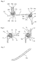
- FIG. 2 shows in a schematic perspective partial representation of an outer wall element 22 and an inserted into an opening 44 of the outer wall member 22 strut cladding element 38. From this illustration of FIG. 2 it is also possible to see the receiving space 46 formed by the strut cladding element 38, through which the carrier element 16 can extend ( Fig. 1 ). As already with reference to the FIG. 1 indicated, the outer wall member 22 in its axially front region (with respect to the flow direction of the exhaust gas), the hook-like fastening portion 28, wherein in the FIG. 2 no corresponding counterpart 30 of the outer housing 14 (FIG. FIG. 1 ) is shown. The axially rear end of the receiving plate 22 has a further hook-like fastening element 28 which is connected to a corresponding counterpart 30 of the outer housing.
- an outer wall element 22 applies analogously to an inner wall element 24, even if such is not included in a corresponding representation in the present application.
- the inner wall elements 24 also have an opening analogous to the opening 44 into which a radially lower end of the strut cladding element 38 can be received.
- FIG. 2 It should be noted that not all of the circumferentially adjacent outer wall members 22 have an opening 44 has, as there are usually fewer support elements 16 than outer wall elements 22 and inner wall elements 24. This is in particular also shown by the fact that there is an outer wall member 22 ', in which no opening 44 is provided.
- the outer wall elements 22, the inner wall elements 24 and the strut cladding elements 38 are made partially or entirely of ceramic fiber composites (CMC).
- CMC ceramic fiber composites
- FIG. 3 shows a partially sectioned schematic perspective view of the outer wall member 22 and the strut cladding element 38 received therein approximately along a section line III-III of FIG. 2 ,
- the strut cladding member 38 is received in the opening 44 of the outer wall member 22.
- the aperture 44 may preferably be bounded by a radially-facing bead or flange-like portion 48.
- the strut cladding member 38 and the outer wall member 22 are supported and sealed against each other by means of a trim seal assembly 50a.
- the trim seal assembly 50a includes a recess 52a formed on the strut trim member 38.
- the recess 52a is preferably designed in cross-section U-shaped or semicircular or arcuate.
- the recess 52a is arranged continuously around a wall 54 delimiting the receiving space 46.
- a sealing strip 56 can be inserted to seal the transition between strut cladding element 38 and outer wall element 22, the example of the FIG. 7 is schematically visible.
- Such a sealing strip is preferably designed as a fabric tube with a resilient or deformable filling.
- the filling can be formed from oriented in the longitudinal direction of the sealing strip 56 ceramic fibers. Alternatively, the filling may also include undirected shorter ceramic fibers, or some kind of ceramic granules or ceramic granules.
- the fabric hose may be made of a ceramic fabric or a metallic fabric.
- FIG. 3 described sealing arrangement 50a between the strut cladding element 38 and the outer wall member 22 may be performed in an analogous manner between the strut cladding element 38 and the inner wall member 24.
- FIG. 3 lying in front of 180 ° in the drawing plane, so that the FIG. 3 upside down, it could also be considered as a schematic representation of the arrangement of the strut cladding element 38 on an inner wall element 24.
- FIG. 4 shows the radially upper portion of the strut cladding element 38 in a simplified perspective view. Evident are the recess 52 a and the receiving space 46 bounding wall 54. From the FIG. 4 is also the most streamlined configuration of the strut cladding element 38 can be seen so that it can be flowed around with the least possible resistance of hot exhaust gas in the flow channel.
- FIG. 5 shows a simplified and schematic sectional view approximately corresponding to the section line VV of FIG. 2
- an outer wall sealing arrangement 50b is provided, which is provided between the adjacent outer wall elements 22 and 22 '.
- Such outer wall seal assembly 50b is also partially in the FIG. 3 can be seen and marked with the same reference numerals.
- the sealing arrangement 50b comprises a recess 52b or 52b 'formed in the outer wall element 22 or in the outer wall element 22', whereby this recess 52b, 52b 'is essentially U-shaped or semicircular or arcuate in cross-section.
- a sealing strand 56 FIG.
- the trim seal assembly 50a can also be seen with the recess 52a provided on the strut cover member 38 and the sealing strip 56 received therein.
- the outer wall member 22 rests with the edge portion 48, the opening 44.
- expansion gaps 58a and 58b are formed between adjacent outer wall elements 22, 22 'and between the outer wall element 22 and the strut cladding element 38, respectively.
- FIG. 6 shows by way of example two sealing arrangements 50 in a generalized form of illustration.
- Each sealing arrangement 50 comprises a first component 70 and a second component 72.
- a recess 52 is formed with an inner portion 74.
- a sealing strand 56 is received in the recess 52.
- the sealing strand 56 is applied to the curved or curved contour of the inner portion 74.
- the depressions 52 point in FIG. 6 each at its right edge on a flange portion 60 which can serve to support 50 acting forces of adjacent components in the region of the seal assembly.
- the flange portion 60 of the first member 70 may support a respective flange-like portion 76 of the second member 72.
- the embodiment with an angled flange portion 60 according to the left side of FIG. 6 is for example also for the flange portions 60b and 60b 'of the outer wall elements 22 and 22' of the FIG. 5 implemented.
- the two outer wall elements 22 and 22 ' form the first and the second component of a sealing arrangement.
- the strut covering element 38 forms the first component
- the outer wall element 22 forms the second component of a sealing arrangement with sealing strip 56.
- the flange portion 60a of the strut cladding member 38 is, as is apparent FIG. 4 can be seen, arranged circumferentially around the receiving space 46.
- the flange portion 60 a in a substantially radial direction with clearance (expansion gap 58 a) can be received in the opening 44 of the outer wall member 22.
- the flange section 60a can be supported on the bead or flange section 48 of the opening 44 during mechanical-thermal loading and associated expansion of the components connected to one another, so that the strut covering element 38 and the outer wall element 22 are supported on one another in this area and achieve a stabilizing effect overall becomes.
- the flange sections 60b and 60b ' have the expansion gaps 58b therebetween and, in the case of a mechanical-thermal load and with expansion of the outer wall elements 22 or 22', can bear on one another in order to support the forces occurring.
- the flange portions 60b and 60b ' also act as reinforcing ribs which give the outer wall member 22 or 22' more stability.
- FIG. 5 could also be the FIG. 5 rotated in the drawing plane by 180 °, so that it is upside down, which could get a basic picture of the situation with interior wall elements.
- sealing strip 56 is deformable in the transverse direction, manufacturing tolerances or necessary clearance existing between the outer wall elements 22 or between the inner wall elements 24 or between the strut lining elements and the wall elements can nevertheless be sufficiently and reliably sealed (see, for example, deformed sealing strip 56 of the sealing arrangement 50a in FIG. 5 ).
- the sealing strands used adapt in shape to the thermal-mechanical conditions when the different components expand during operation of the gas turbine.
- weight can be saved as compared to a conventional metal construction as well as higher gas temperatures. Since more individual outer wall elements or inner wall elements must be arranged together and sealed against each other to form the entire outer wall or the entire inner wall, the deformable sealing strands with a relatively large diameter can be advantageously used.
- seal assembly 50 in particular with reference to a turbine intermediate housing has been explained in more detail for the use and the use of the seal assembly is not a restriction. Rather, such a seal arrangement in other components of a turbine, in particular aircraft gas turbine, an aircraft, a vehicle, another machine or device can be used.
- the presented seal arrangement can be used in particular wherever metallic components are to be replaced by a plurality of CMC components and the CMC component must be sealed against each other.
- the sealing arrangement presented here also allows a floating storage of components.
Landscapes
- Engineering & Computer Science (AREA)
- General Engineering & Computer Science (AREA)
- Mechanical Engineering (AREA)
- Physics & Mathematics (AREA)
- Geometry (AREA)
- Gasket Seals (AREA)
- Turbine Rotor Nozzle Sealing (AREA)
Priority Applications (3)
| Application Number | Priority Date | Filing Date | Title |
|---|---|---|---|
| EP16156681.5A EP3208428B1 (fr) | 2016-02-22 | 2016-02-22 | Agencement d'étanchéification en matériaux composites à fibres ceramiques |
| ES16156681T ES2797731T3 (es) | 2016-02-22 | 2016-02-22 | Estructura de sellado de materiales compuestos de fibra cerámica |
| US15/433,385 US10151209B2 (en) | 2016-02-22 | 2017-02-15 | Sealing system made of ceramic fiber composite materials |
Applications Claiming Priority (1)
| Application Number | Priority Date | Filing Date | Title |
|---|---|---|---|
| EP16156681.5A EP3208428B1 (fr) | 2016-02-22 | 2016-02-22 | Agencement d'étanchéification en matériaux composites à fibres ceramiques |
Publications (2)
| Publication Number | Publication Date |
|---|---|
| EP3208428A1 true EP3208428A1 (fr) | 2017-08-23 |
| EP3208428B1 EP3208428B1 (fr) | 2020-04-01 |
Family
ID=55446632
Family Applications (1)
| Application Number | Title | Priority Date | Filing Date |
|---|---|---|---|
| EP16156681.5A Not-in-force EP3208428B1 (fr) | 2016-02-22 | 2016-02-22 | Agencement d'étanchéification en matériaux composites à fibres ceramiques |
Country Status (3)
| Country | Link |
|---|---|
| US (1) | US10151209B2 (fr) |
| EP (1) | EP3208428B1 (fr) |
| ES (1) | ES2797731T3 (fr) |
Families Citing this family (7)
| Publication number | Priority date | Publication date | Assignee | Title |
|---|---|---|---|---|
| US9759079B2 (en) | 2015-05-28 | 2017-09-12 | Rolls-Royce Corporation | Split line flow path seals |
| ES2723623T3 (es) * | 2016-02-22 | 2019-08-29 | MTU Aero Engines AG | Carcasa intermedia de turbinas de materiales compuestos de fibra cerámica |
| GB201612293D0 (en) * | 2016-07-15 | 2016-08-31 | Rolls Royce Plc | Assembly for supprting an annulus |
| US10718226B2 (en) | 2017-11-21 | 2020-07-21 | Rolls-Royce Corporation | Ceramic matrix composite component assembly and seal |
| US11319827B2 (en) | 2019-04-01 | 2022-05-03 | Raytheon Technologies Corporation | Intersegment seal for blade outer air seal |
| US11629615B2 (en) * | 2021-05-27 | 2023-04-18 | Pratt & Withney Canada Corp. | Strut reinforcing structure for a turbine exhaust case |
| US11655758B1 (en) * | 2022-03-31 | 2023-05-23 | Raytheon Technologies Corporation | CMC vane mate face flanges with through-ply seal slots |
Citations (4)
| Publication number | Priority date | Publication date | Assignee | Title |
|---|---|---|---|---|
| GB2271396A (en) * | 1992-10-09 | 1994-04-13 | Rolls Royce Plc | Multi-layer seal member |
| EP2412929A1 (fr) * | 2009-03-26 | 2012-02-01 | IHI Corporation | Ensemble aube de stator de turbine cmc |
| EP2784272A2 (fr) * | 2013-03-28 | 2014-10-01 | Rolls-Royce plc | Segment d'étanchéité d'une turbine à gaz à materiau composite de matrice céramique |
| WO2015157751A1 (fr) * | 2014-04-11 | 2015-10-15 | General Electric Company | Ensemble de carénage de cadre central de turbine |
Family Cites Families (11)
| Publication number | Priority date | Publication date | Assignee | Title |
|---|---|---|---|---|
| US2420104A (en) * | 1943-07-22 | 1947-05-06 | Maytag Co | Seal guard ring |
| US5082293A (en) * | 1990-11-09 | 1992-01-21 | The United States Of America As Represented By The Administrator Of The National Aeronautics And Space Administration | High temperature, flexible, fiber-preform seal |
| US5630700A (en) | 1996-04-26 | 1997-05-20 | General Electric Company | Floating vane turbine nozzle |
| US6464456B2 (en) | 2001-03-07 | 2002-10-15 | General Electric Company | Turbine vane assembly including a low ductility vane |
| US6655913B2 (en) | 2002-01-15 | 2003-12-02 | General Electric Company | Composite tubular woven seal for an inner compressor discharge case |
| US7600970B2 (en) | 2005-12-08 | 2009-10-13 | General Electric Company | Ceramic matrix composite vane seals |
| US9175573B2 (en) | 2012-11-28 | 2015-11-03 | General Electric Company | Dovetail attachment seal for a turbomachine |
| EP2964889B1 (fr) | 2013-03-04 | 2017-10-18 | Rolls-Royce North American Technologies, Inc. | Compartimentation d'un flux de refroidissement dans une structure comprenant un composant cmc |
| US10969103B2 (en) * | 2013-08-15 | 2021-04-06 | Raytheon Technologies Corporation | Protective panel and frame therefor |
| US10371011B2 (en) * | 2014-05-08 | 2019-08-06 | United Technologies Corporation | Integral ceramic matrix composite fastener with polymer rigidization |
| US10538013B2 (en) * | 2014-05-08 | 2020-01-21 | United Technologies Corporation | Integral ceramic matrix composite fastener with non-polymer rigidization |
-
2016
- 2016-02-22 ES ES16156681T patent/ES2797731T3/es active Active
- 2016-02-22 EP EP16156681.5A patent/EP3208428B1/fr not_active Not-in-force
-
2017
- 2017-02-15 US US15/433,385 patent/US10151209B2/en active Active
Patent Citations (4)
| Publication number | Priority date | Publication date | Assignee | Title |
|---|---|---|---|---|
| GB2271396A (en) * | 1992-10-09 | 1994-04-13 | Rolls Royce Plc | Multi-layer seal member |
| EP2412929A1 (fr) * | 2009-03-26 | 2012-02-01 | IHI Corporation | Ensemble aube de stator de turbine cmc |
| EP2784272A2 (fr) * | 2013-03-28 | 2014-10-01 | Rolls-Royce plc | Segment d'étanchéité d'une turbine à gaz à materiau composite de matrice céramique |
| WO2015157751A1 (fr) * | 2014-04-11 | 2015-10-15 | General Electric Company | Ensemble de carénage de cadre central de turbine |
Also Published As
| Publication number | Publication date |
|---|---|
| US20170241282A1 (en) | 2017-08-24 |
| US10151209B2 (en) | 2018-12-11 |
| ES2797731T3 (es) | 2020-12-03 |
| EP3208428B1 (fr) | 2020-04-01 |
Similar Documents
| Publication | Publication Date | Title |
|---|---|---|
| EP3208433B1 (fr) | Carter intermédiaire de turbine en matière composite à fibres céramiques | |
| EP3208428B1 (fr) | Agencement d'étanchéification en matériaux composites à fibres ceramiques | |
| DE69523545T2 (de) | Verstärkungrahmen für Gasturbinenbrennkammerendstück | |
| CH697788A2 (de) | Mantelhalterungsvorrichtung für Gasturbinen. | |
| EP3199758B1 (fr) | Rotor dans une turbine à gaz de type blisk (disque à aubes) ou bling (bague à aubes) | |
| DE2407960A1 (de) | Statorschaufel und halterung dafuer | |
| CH711981A2 (de) | Kühlsystem für eine mehrwandige Schaufel. | |
| DE102015201782A1 (de) | Leitschaufelring für eine Strömungsmaschine | |
| WO2012072384A1 (fr) | Turbomachine comportant une structure d'étanchéité entre des pièces tournantes et des pièces fixes ainsi que procédé de fabrication de ladite structure d'étanchéité | |
| WO2010086005A2 (fr) | Turbocompresseur à gaz d'échappement pour un moteur à combustion interne | |
| DE102013005167B3 (de) | Abgasturbolader | |
| EP2824288B1 (fr) | Moteur à turbine | |
| EP2762684B1 (fr) | Support d'étanchéité à base d'aluminure de titane pour une turbomachine | |
| DE102014212174A1 (de) | Bürstendichtungssystem zum Abdichten eines Spalts zwischen relativ zueinander bewegbaren Bauteilen einer Strömungsmaschine | |
| EP2394028B1 (fr) | Dispositif d'étanchéité sur l'arbre à aubes d'un étage de rotor d'une turbomachine axiale et son utilisation | |
| EP3287608B1 (fr) | Bague intérieure d'une couronne d'aubes directrices d'une turbomachine | |
| EP3208426B1 (fr) | Segment d'aube directrice pour turbomachine | |
| DE102008020732A1 (de) | Ladeeinrichtung | |
| DE102020126284A1 (de) | Gleitlagerung, sowie eine mit der Gleitlagerung ausgestattete Gondel für eine Windkraftanlage und eine Windkraftanlage | |
| EP2857721B1 (fr) | Système de joint balai destiné à étanchéifier une fente entre des composants mobiles les uns par rapport aux autres d'une turbine à gaz thermique | |
| DE102010003594A1 (de) | Turbinenschaufel mit einem Schwingungsdämpfungselement | |
| EP3293369B1 (fr) | Élément de revêtement pour carter intermédiaire de turbine | |
| CH714607B1 (de) | Verschalung für einen Turbolader und Turbolader. | |
| EP1707759B1 (fr) | Carter d'une turbomachine | |
| DE102015222834A1 (de) | Schaufelcluster mit Umfangssicherung |
Legal Events
| Date | Code | Title | Description |
|---|---|---|---|
| PUAI | Public reference made under article 153(3) epc to a published international application that has entered the european phase |
Free format text: ORIGINAL CODE: 0009012 |
|
| STAA | Information on the status of an ep patent application or granted ep patent |
Free format text: STATUS: THE APPLICATION HAS BEEN PUBLISHED |
|
| AK | Designated contracting states |
Kind code of ref document: A1 Designated state(s): AL AT BE BG CH CY CZ DE DK EE ES FI FR GB GR HR HU IE IS IT LI LT LU LV MC MK MT NL NO PL PT RO RS SE SI SK SM TR |
|
| AX | Request for extension of the european patent |
Extension state: BA ME |
|
| STAA | Information on the status of an ep patent application or granted ep patent |
Free format text: STATUS: REQUEST FOR EXAMINATION WAS MADE |
|
| 17P | Request for examination filed |
Effective date: 20180206 |
|
| RBV | Designated contracting states (corrected) |
Designated state(s): AL AT BE BG CH CY CZ DE DK EE ES FI FR GB GR HR HU IE IS IT LI LT LU LV MC MK MT NL NO PL PT RO RS SE SI SK SM TR |
|
| RIC1 | Information provided on ipc code assigned before grant |
Ipc: F01D 11/00 20060101AFI20190507BHEP Ipc: F16J 15/06 20060101ALI20190507BHEP |
|
| GRAP | Despatch of communication of intention to grant a patent |
Free format text: ORIGINAL CODE: EPIDOSNIGR1 |
|
| STAA | Information on the status of an ep patent application or granted ep patent |
Free format text: STATUS: GRANT OF PATENT IS INTENDED |
|
| INTG | Intention to grant announced |
Effective date: 20190927 |
|
| GRAS | Grant fee paid |
Free format text: ORIGINAL CODE: EPIDOSNIGR3 |
|
| GRAA | (expected) grant |
Free format text: ORIGINAL CODE: 0009210 |
|
| STAA | Information on the status of an ep patent application or granted ep patent |
Free format text: STATUS: THE PATENT HAS BEEN GRANTED |
|
| AK | Designated contracting states |
Kind code of ref document: B1 Designated state(s): AL AT BE BG CH CY CZ DE DK EE ES FI FR GB GR HR HU IE IS IT LI LT LU LV MC MK MT NL NO PL PT RO RS SE SI SK SM TR |
|
| REG | Reference to a national code |
Ref country code: GB Ref legal event code: FG4D Free format text: NOT ENGLISH |
|
| REG | Reference to a national code |
Ref country code: AT Ref legal event code: REF Ref document number: 1251583 Country of ref document: AT Kind code of ref document: T Effective date: 20200415 Ref country code: CH Ref legal event code: EP |
|
| REG | Reference to a national code |
Ref country code: DE Ref legal event code: R096 Ref document number: 502016009337 Country of ref document: DE |
|
| REG | Reference to a national code |
Ref country code: IE Ref legal event code: FG4D Free format text: LANGUAGE OF EP DOCUMENT: GERMAN |
|
| PG25 | Lapsed in a contracting state [announced via postgrant information from national office to epo] |
Ref country code: BG Free format text: LAPSE BECAUSE OF FAILURE TO SUBMIT A TRANSLATION OF THE DESCRIPTION OR TO PAY THE FEE WITHIN THE PRESCRIBED TIME-LIMIT Effective date: 20200701 |
|
| REG | Reference to a national code |
Ref country code: NL Ref legal event code: MP Effective date: 20200401 |
|
| REG | Reference to a national code |
Ref country code: LT Ref legal event code: MG4D |
|
| PG25 | Lapsed in a contracting state [announced via postgrant information from national office to epo] |
Ref country code: PT Free format text: LAPSE BECAUSE OF FAILURE TO SUBMIT A TRANSLATION OF THE DESCRIPTION OR TO PAY THE FEE WITHIN THE PRESCRIBED TIME-LIMIT Effective date: 20200817 Ref country code: CZ Free format text: LAPSE BECAUSE OF FAILURE TO SUBMIT A TRANSLATION OF THE DESCRIPTION OR TO PAY THE FEE WITHIN THE PRESCRIBED TIME-LIMIT Effective date: 20200401 Ref country code: FI Free format text: LAPSE BECAUSE OF FAILURE TO SUBMIT A TRANSLATION OF THE DESCRIPTION OR TO PAY THE FEE WITHIN THE PRESCRIBED TIME-LIMIT Effective date: 20200401 Ref country code: IS Free format text: LAPSE BECAUSE OF FAILURE TO SUBMIT A TRANSLATION OF THE DESCRIPTION OR TO PAY THE FEE WITHIN THE PRESCRIBED TIME-LIMIT Effective date: 20200801 Ref country code: GR Free format text: LAPSE BECAUSE OF FAILURE TO SUBMIT A TRANSLATION OF THE DESCRIPTION OR TO PAY THE FEE WITHIN THE PRESCRIBED TIME-LIMIT Effective date: 20200702 Ref country code: NO Free format text: LAPSE BECAUSE OF FAILURE TO SUBMIT A TRANSLATION OF THE DESCRIPTION OR TO PAY THE FEE WITHIN THE PRESCRIBED TIME-LIMIT Effective date: 20200701 Ref country code: LT Free format text: LAPSE BECAUSE OF FAILURE TO SUBMIT A TRANSLATION OF THE DESCRIPTION OR TO PAY THE FEE WITHIN THE PRESCRIBED TIME-LIMIT Effective date: 20200401 Ref country code: NL Free format text: LAPSE BECAUSE OF FAILURE TO SUBMIT A TRANSLATION OF THE DESCRIPTION OR TO PAY THE FEE WITHIN THE PRESCRIBED TIME-LIMIT Effective date: 20200401 Ref country code: SE Free format text: LAPSE BECAUSE OF FAILURE TO SUBMIT A TRANSLATION OF THE DESCRIPTION OR TO PAY THE FEE WITHIN THE PRESCRIBED TIME-LIMIT Effective date: 20200401 |
|
| PG25 | Lapsed in a contracting state [announced via postgrant information from national office to epo] |
Ref country code: RS Free format text: LAPSE BECAUSE OF FAILURE TO SUBMIT A TRANSLATION OF THE DESCRIPTION OR TO PAY THE FEE WITHIN THE PRESCRIBED TIME-LIMIT Effective date: 20200401 Ref country code: HR Free format text: LAPSE BECAUSE OF FAILURE TO SUBMIT A TRANSLATION OF THE DESCRIPTION OR TO PAY THE FEE WITHIN THE PRESCRIBED TIME-LIMIT Effective date: 20200401 Ref country code: LV Free format text: LAPSE BECAUSE OF FAILURE TO SUBMIT A TRANSLATION OF THE DESCRIPTION OR TO PAY THE FEE WITHIN THE PRESCRIBED TIME-LIMIT Effective date: 20200401 |
|
| REG | Reference to a national code |
Ref country code: ES Ref legal event code: FG2A Ref document number: 2797731 Country of ref document: ES Kind code of ref document: T3 Effective date: 20201203 |
|
| PG25 | Lapsed in a contracting state [announced via postgrant information from national office to epo] |
Ref country code: AL Free format text: LAPSE BECAUSE OF FAILURE TO SUBMIT A TRANSLATION OF THE DESCRIPTION OR TO PAY THE FEE WITHIN THE PRESCRIBED TIME-LIMIT Effective date: 20200401 |
|
| REG | Reference to a national code |
Ref country code: DE Ref legal event code: R097 Ref document number: 502016009337 Country of ref document: DE |
|
| PG25 | Lapsed in a contracting state [announced via postgrant information from national office to epo] |
Ref country code: EE Free format text: LAPSE BECAUSE OF FAILURE TO SUBMIT A TRANSLATION OF THE DESCRIPTION OR TO PAY THE FEE WITHIN THE PRESCRIBED TIME-LIMIT Effective date: 20200401 Ref country code: SM Free format text: LAPSE BECAUSE OF FAILURE TO SUBMIT A TRANSLATION OF THE DESCRIPTION OR TO PAY THE FEE WITHIN THE PRESCRIBED TIME-LIMIT Effective date: 20200401 Ref country code: DK Free format text: LAPSE BECAUSE OF FAILURE TO SUBMIT A TRANSLATION OF THE DESCRIPTION OR TO PAY THE FEE WITHIN THE PRESCRIBED TIME-LIMIT Effective date: 20200401 Ref country code: RO Free format text: LAPSE BECAUSE OF FAILURE TO SUBMIT A TRANSLATION OF THE DESCRIPTION OR TO PAY THE FEE WITHIN THE PRESCRIBED TIME-LIMIT Effective date: 20200401 Ref country code: IT Free format text: LAPSE BECAUSE OF FAILURE TO SUBMIT A TRANSLATION OF THE DESCRIPTION OR TO PAY THE FEE WITHIN THE PRESCRIBED TIME-LIMIT Effective date: 20200401 |
|
| PLBE | No opposition filed within time limit |
Free format text: ORIGINAL CODE: 0009261 |
|
| STAA | Information on the status of an ep patent application or granted ep patent |
Free format text: STATUS: NO OPPOSITION FILED WITHIN TIME LIMIT |
|
| PG25 | Lapsed in a contracting state [announced via postgrant information from national office to epo] |
Ref country code: SK Free format text: LAPSE BECAUSE OF FAILURE TO SUBMIT A TRANSLATION OF THE DESCRIPTION OR TO PAY THE FEE WITHIN THE PRESCRIBED TIME-LIMIT Effective date: 20200401 Ref country code: PL Free format text: LAPSE BECAUSE OF FAILURE TO SUBMIT A TRANSLATION OF THE DESCRIPTION OR TO PAY THE FEE WITHIN THE PRESCRIBED TIME-LIMIT Effective date: 20200401 |
|
| 26N | No opposition filed |
Effective date: 20210112 |
|
| PG25 | Lapsed in a contracting state [announced via postgrant information from national office to epo] |
Ref country code: SI Free format text: LAPSE BECAUSE OF FAILURE TO SUBMIT A TRANSLATION OF THE DESCRIPTION OR TO PAY THE FEE WITHIN THE PRESCRIBED TIME-LIMIT Effective date: 20200401 |
|
| PGFP | Annual fee paid to national office [announced via postgrant information from national office to epo] |
Ref country code: GB Payment date: 20210222 Year of fee payment: 6 |
|
| PG25 | Lapsed in a contracting state [announced via postgrant information from national office to epo] |
Ref country code: MC Free format text: LAPSE BECAUSE OF FAILURE TO SUBMIT A TRANSLATION OF THE DESCRIPTION OR TO PAY THE FEE WITHIN THE PRESCRIBED TIME-LIMIT Effective date: 20200401 |
|
| REG | Reference to a national code |
Ref country code: BE Ref legal event code: MM Effective date: 20210228 |
|
| PG25 | Lapsed in a contracting state [announced via postgrant information from national office to epo] |
Ref country code: LU Free format text: LAPSE BECAUSE OF NON-PAYMENT OF DUE FEES Effective date: 20210222 Ref country code: LI Free format text: LAPSE BECAUSE OF NON-PAYMENT OF DUE FEES Effective date: 20210228 Ref country code: CH Free format text: LAPSE BECAUSE OF NON-PAYMENT OF DUE FEES Effective date: 20210228 |
|
| PG25 | Lapsed in a contracting state [announced via postgrant information from national office to epo] |
Ref country code: IE Free format text: LAPSE BECAUSE OF NON-PAYMENT OF DUE FEES Effective date: 20210222 |
|
| REG | Reference to a national code |
Ref country code: AT Ref legal event code: MM01 Ref document number: 1251583 Country of ref document: AT Kind code of ref document: T Effective date: 20210222 |
|
| PG25 | Lapsed in a contracting state [announced via postgrant information from national office to epo] |
Ref country code: AT Free format text: LAPSE BECAUSE OF NON-PAYMENT OF DUE FEES Effective date: 20210222 |
|
| PGFP | Annual fee paid to national office [announced via postgrant information from national office to epo] |
Ref country code: DE Payment date: 20220217 Year of fee payment: 7 |
|
| PGFP | Annual fee paid to national office [announced via postgrant information from national office to epo] |
Ref country code: FR Payment date: 20220221 Year of fee payment: 7 Ref country code: ES Payment date: 20220318 Year of fee payment: 7 |
|
| PG25 | Lapsed in a contracting state [announced via postgrant information from national office to epo] |
Ref country code: BE Free format text: LAPSE BECAUSE OF NON-PAYMENT OF DUE FEES Effective date: 20210228 |
|
| GBPC | Gb: european patent ceased through non-payment of renewal fee |
Effective date: 20220222 |
|
| PG25 | Lapsed in a contracting state [announced via postgrant information from national office to epo] |
Ref country code: GB Free format text: LAPSE BECAUSE OF NON-PAYMENT OF DUE FEES Effective date: 20220222 |
|
| PG25 | Lapsed in a contracting state [announced via postgrant information from national office to epo] |
Ref country code: HU Free format text: LAPSE BECAUSE OF FAILURE TO SUBMIT A TRANSLATION OF THE DESCRIPTION OR TO PAY THE FEE WITHIN THE PRESCRIBED TIME-LIMIT; INVALID AB INITIO Effective date: 20160222 |
|
| PG25 | Lapsed in a contracting state [announced via postgrant information from national office to epo] |
Ref country code: CY Free format text: LAPSE BECAUSE OF FAILURE TO SUBMIT A TRANSLATION OF THE DESCRIPTION OR TO PAY THE FEE WITHIN THE PRESCRIBED TIME-LIMIT Effective date: 20200401 |
|
| REG | Reference to a national code |
Ref country code: DE Ref legal event code: R119 Ref document number: 502016009337 Country of ref document: DE |
|
| PG25 | Lapsed in a contracting state [announced via postgrant information from national office to epo] |
Ref country code: FR Free format text: LAPSE BECAUSE OF NON-PAYMENT OF DUE FEES Effective date: 20230228 Ref country code: DE Free format text: LAPSE BECAUSE OF NON-PAYMENT OF DUE FEES Effective date: 20230901 |
|
| REG | Reference to a national code |
Ref country code: ES Ref legal event code: FD2A Effective date: 20240405 |
|
| PG25 | Lapsed in a contracting state [announced via postgrant information from national office to epo] |
Ref country code: ES Free format text: LAPSE BECAUSE OF NON-PAYMENT OF DUE FEES Effective date: 20230223 |
|
| PG25 | Lapsed in a contracting state [announced via postgrant information from national office to epo] |
Ref country code: MK Free format text: LAPSE BECAUSE OF FAILURE TO SUBMIT A TRANSLATION OF THE DESCRIPTION OR TO PAY THE FEE WITHIN THE PRESCRIBED TIME-LIMIT Effective date: 20200401 Ref country code: ES Free format text: LAPSE BECAUSE OF NON-PAYMENT OF DUE FEES Effective date: 20230223 |
|
| PG25 | Lapsed in a contracting state [announced via postgrant information from national office to epo] |
Ref country code: TR Free format text: LAPSE BECAUSE OF FAILURE TO SUBMIT A TRANSLATION OF THE DESCRIPTION OR TO PAY THE FEE WITHIN THE PRESCRIBED TIME-LIMIT Effective date: 20200401 |
|
| PG25 | Lapsed in a contracting state [announced via postgrant information from national office to epo] |
Ref country code: MT Free format text: LAPSE BECAUSE OF FAILURE TO SUBMIT A TRANSLATION OF THE DESCRIPTION OR TO PAY THE FEE WITHIN THE PRESCRIBED TIME-LIMIT Effective date: 20200401 |