EP3209229B1 - Dispositif de fixation d'une tige sur un os - Google Patents
Dispositif de fixation d'une tige sur un os Download PDFInfo
- Publication number
- EP3209229B1 EP3209229B1 EP16770206.7A EP16770206A EP3209229B1 EP 3209229 B1 EP3209229 B1 EP 3209229B1 EP 16770206 A EP16770206 A EP 16770206A EP 3209229 B1 EP3209229 B1 EP 3209229B1
- Authority
- EP
- European Patent Office
- Prior art keywords
- tulip
- screw
- rod clamp
- accordance
- rod
- Prior art date
- Legal status (The legal status is an assumption and is not a legal conclusion. Google has not performed a legal analysis and makes no representation as to the accuracy of the status listed.)
- Active
Links
Images


Classifications
-
- A—HUMAN NECESSITIES
- A61—MEDICAL OR VETERINARY SCIENCE; HYGIENE
- A61B—DIAGNOSIS; SURGERY; IDENTIFICATION
- A61B17/00—Surgical instruments, devices or methods
- A61B17/56—Surgical instruments or methods for treatment of bones or joints; Devices specially adapted therefor
- A61B17/58—Surgical instruments or methods for treatment of bones or joints; Devices specially adapted therefor for osteosynthesis, e.g. bone plates, screws or setting implements
- A61B17/68—Internal fixation devices, including fasteners and spinal fixators, even if a part thereof projects from the skin
- A61B17/70—Spinal positioners or stabilisers, e.g. stabilisers comprising fluid filler in an implant
- A61B17/7001—Screws or hooks combined with longitudinal elements which do not contact vertebrae
- A61B17/7035—Screws or hooks, wherein a rod-clamping part and a bone-anchoring part can pivot relative to each other
- A61B17/7037—Screws or hooks, wherein a rod-clamping part and a bone-anchoring part can pivot relative to each other wherein pivoting is blocked when the rod is clamped
-
- A—HUMAN NECESSITIES
- A61—MEDICAL OR VETERINARY SCIENCE; HYGIENE
- A61B—DIAGNOSIS; SURGERY; IDENTIFICATION
- A61B17/00—Surgical instruments, devices or methods
- A61B17/56—Surgical instruments or methods for treatment of bones or joints; Devices specially adapted therefor
- A61B17/58—Surgical instruments or methods for treatment of bones or joints; Devices specially adapted therefor for osteosynthesis, e.g. bone plates, screws or setting implements
- A61B17/68—Internal fixation devices, including fasteners and spinal fixators, even if a part thereof projects from the skin
- A61B17/70—Spinal positioners or stabilisers, e.g. stabilisers comprising fluid filler in an implant
- A61B17/7001—Screws or hooks combined with longitudinal elements which do not contact vertebrae
- A61B17/7032—Screws or hooks with U-shaped head or back through which longitudinal rods pass
-
- A—HUMAN NECESSITIES
- A61—MEDICAL OR VETERINARY SCIENCE; HYGIENE
- A61B—DIAGNOSIS; SURGERY; IDENTIFICATION
- A61B17/00—Surgical instruments, devices or methods
- A61B17/56—Surgical instruments or methods for treatment of bones or joints; Devices specially adapted therefor
- A61B17/58—Surgical instruments or methods for treatment of bones or joints; Devices specially adapted therefor for osteosynthesis, e.g. bone plates, screws or setting implements
- A61B17/68—Internal fixation devices, including fasteners and spinal fixators, even if a part thereof projects from the skin
- A61B17/70—Spinal positioners or stabilisers, e.g. stabilisers comprising fluid filler in an implant
- A61B17/7074—Tools specially adapted for spinal fixation operations other than for bone removal or filler handling
- A61B17/7076—Tools specially adapted for spinal fixation operations other than for bone removal or filler handling for driving, positioning or assembling spinal clamps or bone anchors specially adapted for spinal fixation
-
- A—HUMAN NECESSITIES
- A61—MEDICAL OR VETERINARY SCIENCE; HYGIENE
- A61B—DIAGNOSIS; SURGERY; IDENTIFICATION
- A61B17/00—Surgical instruments, devices or methods
- A61B17/56—Surgical instruments or methods for treatment of bones or joints; Devices specially adapted therefor
- A61B17/58—Surgical instruments or methods for treatment of bones or joints; Devices specially adapted therefor for osteosynthesis, e.g. bone plates, screws or setting implements
- A61B17/68—Internal fixation devices, including fasteners and spinal fixators, even if a part thereof projects from the skin
- A61B17/84—Fasteners therefor or fasteners being internal fixation devices
- A61B17/86—Pins or screws or threaded wires; nuts therefor
- A61B17/8625—Shanks, i.e. parts contacting bone tissue
- A61B17/863—Shanks, i.e. parts contacting bone tissue with thread interrupted or changing its form along shank, other than constant taper
-
- A—HUMAN NECESSITIES
- A61—MEDICAL OR VETERINARY SCIENCE; HYGIENE
- A61B—DIAGNOSIS; SURGERY; IDENTIFICATION
- A61B17/00—Surgical instruments, devices or methods
- A61B17/56—Surgical instruments or methods for treatment of bones or joints; Devices specially adapted therefor
- A61B17/58—Surgical instruments or methods for treatment of bones or joints; Devices specially adapted therefor for osteosynthesis, e.g. bone plates, screws or setting implements
- A61B17/68—Internal fixation devices, including fasteners and spinal fixators, even if a part thereof projects from the skin
- A61B17/84—Fasteners therefor or fasteners being internal fixation devices
- A61B17/86—Pins or screws or threaded wires; nuts therefor
- A61B17/864—Pins or screws or threaded wires; nuts therefor hollow, e.g. with socket or cannulated
-
- A—HUMAN NECESSITIES
- A61—MEDICAL OR VETERINARY SCIENCE; HYGIENE
- A61B—DIAGNOSIS; SURGERY; IDENTIFICATION
- A61B90/00—Instruments, implements or accessories specially adapted for surgery or diagnosis and not covered by any of the groups A61B1/00 - A61B50/00, e.g. for luxation treatment or for protecting wound edges
- A61B90/03—Automatic limiting or abutting means, e.g. for safety
- A61B2090/037—Automatic limiting or abutting means, e.g. for safety with a frangible part, e.g. by reduced diameter
Definitions
- the invention relates to a device for fastening a rod to a bone according to the preamble of claim 1.
- the EP 2 363 086 A1 shows a transpedicular screw with a head 1 and a shaft provided with a screw thread, the head 1 being integral and rigidly connected to the shaft of the pedicle screw and the wall in the head 1 being interrupted by a diametrical slot through which the fastening or connecting rod 7 can extend.
- a "lower part" (lower part 3), which allows an orientation deviating from a right angle relative to the main axis - the pedicle screw - due to a partially cylindrical underside of the element 3 facing away from the connecting rod
- there is obviously no (rotational) degree of freedom since the side walls of part 3, like those of part 4, are obviously planar; nothing is said about this either.
- the diameter of the pressure element is reduced on at least one of its end faces compared to the inner diameter of the tulip.
- the lower part 3 of the D1 has its widest extent in the radial direction on its proximal end face.
- the invention is based on the object of further developing a device of the generic type in such a way that it enables further degrees of freedom and, in particular, a less stressful and less dangerous use for a patient.
- a rod clamp is provided between the latter and the (transverse) rod to be braced in the tulip head, which rod clamp can also be pivoted relative to the tensioning screw.
- the invention thus also includes a system of at least one device according to the invention and a (connecting) rod, in which the clamped rod between the tensioning screw and rod clamp is connected to each of the two at least via a contact line, possibly also over a large area, (but not only punctiform).
- a contact line possibly also over a large area, (but not only punctiform).
- a preferred embodiment of the device according to the invention is characterized in that the rod clamp and tensioning screw have spherical zones on both sides facing one another and oriented obliquely to a main axis (A), over which they can be pivoted relatively.
- the spherical zones are preferably formed in the jacket area of the tensioning screw and rod clamp.
- the clamping screw At its distal end of the end face, the clamping screw preferably has an annular end face in the form of a spherical zone (as a jacket of a spherical layer) and the rod clamp a corresponding proximal end face in the form of a spherical zone.
- Proximal denotes an area of the device facing an operator or user - axially - and, distally, an area of the device facing away from this and thus facing a patient or lying in this area of the device during use.
- a rod clamp adapter connecting the clamping screw and the rod clamp is provided, the rod clamp adapter being a ring part with proximal outwardly radially directed projections which engage in radial incisions in the clamping screw with play, in particular distal, also radially outwardly directed projections being given that engage in radial notches in the rod clamp.
- a radial annular groove is formed as an undercut proximally behind the end face of the clamping screw.
- a rod clamp for the rod to be clamped points to her The proximal end facing the clamping screw has an end face which also runs obliquely to a main longitudinal axis and corresponds to the end face.
- the rod clamp is also provided with a radial annular groove on the inside of its jacket. Radially outwardly formed projections of the annular rod clamp adapter engage in the annular groove in order to secure the rod clamp on the clamping screw against falling out.
- the tensioning screw and the rod clamp have undercuts reaching behind one another, whereby a pivotable connection between the tensioning screw and the rod clamp is provided.
- the undercut of the clamping screw is formed by an annular projection and / or that the undercut of the rod clamp is formed on more than two elastic fingers arranged around the circumference.
- the number of rings and undercuts on these is preferably four to eight.
- the clamping screw has an inner cone which tapers away from the undercut. This ensures that even with a non-axial alignment, i.e. pivoting or tilting between the tensioning screw and the rod clamp, there is always a fixed radial position between the two parts, since the area of the rod clamp moving towards the proximal or tapered area of the inner cone of the tensioning screw is due to the tapered conical design is pressed to the side and the opposite in the enlarged or distal area of the recess of the clamping screw corresponding to the side in this area also rests on the circumferential wall of the clamping screw.
- the rod clamp has a part-circular recess on its side facing away from the clamping screw.
- a partially circular recess has an axis of symmetry perpendicular to the main axis of symmetry of the tensioning clamp and, in the case of an axially elongated arrangement, the same with the axis of symmetry of the tensioning screw.
- the part-circular recess of the rod clamp can therefore encompass the rod over part of its circumference.
- the tensioning screw has an asymmetrical thread, in particular a flank of the thread of the tensioning screw that is directed proximally to the tightening direction below an angle of less than or equal to 5 °, in particular less than or equal to 3 ° or not equal to 0 °, to a radial plane to the axis of symmetry of the clamping screw and / or a flank of the thread of the clamping screw directed in the tightening direction (distal) extends at an angle other than 90 ° to the
- the axis of symmetry of the clamping screw preferably by 30 °, extends to a radial plane.
- the flanks are directed proximally to the vertical longitudinal axis of the screw.
- the clamping screw has a multiple rotationally symmetrical (non-cylindrical) recess on its side facing away from the rod clamp.
- a complementary screw tool for screwing the screw into the tulip of the device can thus engage with this proximal, non-cylindrical recess of the clamping screw.
- Another embodiment of the invention is characterized in that the pressure element is tiltably mounted in the tulip.
- the diameter of the pressure element is reduced on at least one of its end faces compared to the inner diameter of the tulip, so that the pressure element can be tilted within the tulip.
- the pressure element of the tulip tapers from its distal to its proximal end face, so that there is a radial clearance proximally between the inner wall of the tulip and the outer wall of the pressure element or that the inner wall of the tulip extends from the height of the proximal to the height of the distal end face of the pressure element expanded while ensuring a radial play between the pressure element and tulip at the level of the distal end face of the pressure element.
- the pressure element that is distally opposite the rod clamp and clamps the rod between it and itself in connection or relationship to the interior of the surrounding tulip is designed and / or supported such that the pressure element also enables and supports the alignment of the clamped rod made possible by the clamping device not disabled.
- a fastening device has a pedicle screw, a pressure element and a tulip. It also has a tensioning device with a tensioning screw and a rod clamp. All of these parts are cannulated, i.e. they have an axially extending central cavity.
- the tulip holds the pedicle screw and, after screwing the latter into a bone, serves to support a rod.
- the tulip is therefore a deposit of rods and is also referred to as such.
- the tulip is proximally connected to a tulip extension via a predetermined breaking point.
- Tulip and tulip extension have an internal thread extending over both and in the wall of both diametrically opposite elongated holes.
- the pedicle screw has a pedicle screw shaft with a self-tapping pedicle thread and, at the proximal end, a pedicle screw head which is surrounded by the tulip.
- a pressure element for the rod is arranged as an abutment in the distal area of the tulip.
- the screw shaft of the pedicle screw has a double thread, in particular a proximal area of the screw shaft is designed as a quadruple thread, preferably over a length of a quarter of the pedicle screw shaft. This results in a better hold of the screw in the bone.
- a double thread has two screw threads. These are twisted into one another.
- the transition from screw thread projection or serration to the screw shaft is rounded off with a finite radius of curvature of the transition. This increases the stability of the screw and prevents the screw flanks from breaking off.
- the pedicle screw shaft is provided with openings around a jacket to its inner lumen.
- Pasty masses such as bone cement, in particular, can be introduced through a lumen of the screw and openings. It is essential that the breakthroughs are present in the distal area of the screw so that they can be removed after the Screw lie within the vertebral body (and not in the bone area) so that cement can then be introduced through this into the interior of the vertebral body for fixation.
- An external thread of the clamping screw is matched to an internal thread of the tulip.
- a rod inserted in the tulip is clamped between the rod clamp, which encompasses it from the proximal side and on which the clamping screw acts, and the distal pressure element, by means of which the rod can be clamped at angles equal to or not equal to 90 °, in particular to the device axis .
- clamping screw thread At the proximal end of the clamping screw there is a multiple, non-cylindrical recess for positive engagement with a screwing tool to transmit a torque to the clamping screw.
- the outside of the clamping screw is provided with an asymmetrical clamping screw thread, in particular in the form of a special buttress thread.
- the tensioning screw has proximally behind its distal end face an annular projection in the form of an inner cone extending proximally from the distal end face, which is connected via an undercut proximally to an inner cone tapering the lumen of the tensioning screw in the proximal direction, which radially at the distal end area of the recess of the tensioning screw has a larger diameter than the recess.
- the rod clamp has a number of circumferentially juxtaposed and proximally and radially inwardly directed elastic fingers with radially outwardly pointing noses which cooperate with the undercuts of the clamping screw in that the noses engage with their undercuts in the undercut of the clamping screw formed by the annular projection.
- the distal end face of the rod clamp has a partially cylindrical clamping recess for receiving the transverse rod.
- a polyaxial pressure element has a partially cylindrical recess on its proximal side for partially embracing or receiving the rod, while another hemispherical or dome-shaped recess is provided on the distal end face of the pressure element in order to grasp a spherical screw head of the pedicle screw.
- the pressure element - distal compared to the rod - has a jacket which tapers from its distal end to the proximal end, so that a gap is formed between this and the inner wall of the tulip. This enables the pressure element to be tilted within the tulip in relation to an axially formed central position.
- the partially cylindrical recess has a radius of curvature such that rods with different diameters, such as between 5 mm and 6 mm, can be used.
- the pressure element has pressure surfaces on its outside for transverse screws that can be screwed in radially from the outside through the tulip for fixing the pressure element inside the tulip.
- the polyaxial pedicle screw has a spherical pedicle screw head which can be pivoted in all directions without restriction in the spherical recess on the distal area of the polyaxial pressure element.
- the screw head and thus the pedicle screw 2 is held captively in the tulip by means of the pressure element, since at its distal end it has an opening that is narrowed in relation to the diameter of the screw head.
- a monoaxial pressure element has a flat, frustoconical distal end face facing the screw head of the pedicle screw, with a conical ring-shaped peripheral edge which surrounds a central opening.
- the pressure element and pedicle screw can be rotated relative to one another, but always remain monoaxially aligned along an axis that corresponds to the axis of the tulip and the clamping screw screwed into it.
- the inner wall of the tulip has a step and, proximally behind this, an expansion which tapers monoaxially in the proximal direction.
- the screw head extends proximally up to this step into the tulip.
- the - monoaxial - The pressure element only begins there distally and has a smaller diameter than the extension of the tulip at its distal end, so that there is a certain lateral play and so the monoaxial pressure element in the tulip can be tilted slightly in order to allow the clamping device not to hinder the eccentric alignment of the rod, but rather to accommodate and enable it.
- a monoaxial pedicle screw has at its proximal end a - monoaxial - pedicle screw head which can be pivoted accordingly.
- the screw head has a cylindrical jacket and a flat, proximal end-face recess with an edge which is likewise conical-ring-shaped and adapted to the peripheral edge of the pressure element.
- the clamping device with the rod clamp allows tilted arrangements of the connecting rod to be adjusted by corresponding pivoting movement of the rod clamp and the pressure element, which on the one hand reduces the stress on the fastening device and on the other hand at least considerably reduces the stress on the patient; the stability of the fastening device, in particular its long-term stability, are significantly increased as a result. Due to the variability of the alignment of the cross bar in the device, the stability of the structure is thus improved.
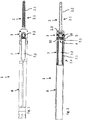
- Fig. 1 shows a fastening device 1 with a - polyaxial - pedicle screw 2 and a tulip 3.
- the device 1 has a main axis A in its longitudinal direction. It also has a clamping device 4 with a clamping screw 5 and a rod clamp 6, which in section in the Fig. 2 and especially too Fig. 3 are shown. All of these parts are cannulated, ie they have an axially extending central cavity.
- proximal denotes an area of the device 1 facing a surgeon or user - axially - and distally an area of the device 1 facing away from the latter and thus facing a patient or lying in this area of the device 1 during use.
- the tulip 3 holds the pedicle screw 2 and, after screwing the latter into a bone, in particular a vertebra, serves to support a rod 10 ( Fig. 2 , 3 ) which extends in particular in the direction of the spine or a long bone or in the direction of a flat bone and which is also held by further tulips with pedicle screws on another bone / vertebra or another location, e.g. a long bone, and the bones / vertebrae so can fix.
- the tulip 3 is thus a rod deposit and is also referred to as such.
- the tulip 3 is initially connected to a tulip extension 7 via a predetermined breaking point 7.3.
- the predetermined breaking point 7.3 has a radially reduced cross section or a reduced wall thickness.
- the latter has an external thread (not shown) for connection to an extension shaft 8 having a corresponding internal thread.
- the tulip 3 and the tulip extension 7 are cannulated like the extension shaft 8.
- Tulip 3 and tulip extension 7 have an internal thread 3.1, 7.1 extending over both of them. Further extend in the distal area of the tulip extension 7 and in the proximal area of the tulip 3 in the wall of both diametrically opposed elongated holes 3.2, 7.2, which extend axially over most of the tulip extension 7 and over approximately half of the tulip 3.
- the pedicle screw 2 has a pedicle screw shaft 2.1 with a self-tapping pedicle thread 2.2. At the proximal end of the pedicle screw 2, a pedicle screw head 2.3 is formed, which is encompassed by the tulip 3 ( Figs. 1 to 3 ).
- a pressure element 9 is arranged, the mode of operation of which is described below.
- the illustrated pedicle screw 2 has a double thread, ie two screw threads S1, S2 ( Fig. 15 ).
- the pedicle screw 2 can also have a single thread or a multiple thread (other than two).
- the pedicle screw shaft 2.1 is provided with openings 2.4 in a jacket 2.5 to an inner lumen 2.6 of the pedicle screw 2.
- the lumen 2.6 axially penetrates the entire pedicle screw 2. Liquids and / or in particular pasty materials such as cleaning fluids or bone cement can be introduced through the lumen 2.6 and the openings 2.4.
- An external thread 5.2 of a clamping screw 5 is matched to an internal thread 3.1 of the tulip 3 (described in more detail below).
- a rod 10 clamped in the tulip 3 can be seen (in section), which is clamped between the rod clamp 6 which engages around it from the proximal side and which the clamping screw 5 acts on, and the distal pressure element 9.
- the clamping of the rod 10 will be discussed further below.
- the Fig. 3a shows a section through the device 1 according to the invention with a rod 10 at an angle not equal to 90 ° to the device axis - how such an alignment is made possible by the configuration of the individual elements described below.
- the tensioning screw 5 ( Fig. 3 , 3a ) has an axial axis of symmetry that coincides with the main axis A.
- At the proximal At the end of the clamping screw 5 there is a multiple, non-cylindrical recess 5.1 which provides a screw tool (screwdriver, not shown) with a form-fitting engagement for transmitting a torque to the clamping screw 5.
- the recess 5.1 can be designed as a square or polygon, in particular also as a Torx profile.
- the outside of the tensioning screw 5 is provided with the asymmetrical tensioning screw thread 5.2, the tightening direction F being directed distally.
- the clamping screw thread 5.2 is designed as a buttress thread.
- Other thread types, in particular other asymmetrical thread types, are also possible.
- flanks 5.3, 5.4 are inclined in the same direction from the inside to the outside in the proximal direction with respect to (perpendicular to the axis) radial planes, namely the distally directed flank 5.3 of a tooth body here by 30 ° and proximally directed flank 5.4 of the screw thread by 3 °, so that the flank angle (between the two flanks) is 27 °.
- a buttress thread is highly resilient to forces acting against the tightening direction.
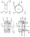
- the clamping screw 5 in this first embodiment has Fig. 3 an annular end face 5.9 in the form of a spherical zone (a spherical layer as a jacket) running obliquely from the outside distally and proximally on the inside to the axis A. Proximally behind this a radial annular groove 5.10 is formed as an undercut.
- a rod clamp 6 for the rod 10 to be clamped has its facing towards the clamping screw 6 proximal end has an end face 6.7 which also runs obliquely to the axis A and corresponds to the end face 5.9.
- the rod clamp 6 is also provided with a radial annular groove 6.8 on the inside of its jacket.
- annular rod clamp adapter (6a) In the annular grooves 5.10, 6.8 - here four - radially outwardly directed projections 6a.1 and 6a.2 of an annular rod clamp adapter (6a), which are not evenly arranged over the circumference, engage in order to secure the rod clamp 6 on the tensioning screw 5 against falling out .
- the rod clamp adapter is preferably welded to the rod clamp 6.
- Fig. 5 shows a clamping screw 5 of the second embodiment of the clamping device 4 in an axial longitudinal section.
- 3a is the clamping screw described, reference is made to the description there.
- the clamping screw 5 has proximally behind its distal end face an annular projection in the form of an inner cone that extends proximally from the distal end face, to which a lumen 5.7 of the clamping screw 5 is connected proximally via an undercut 5.6, which tapers in the proximal direction and which axially at the distal end area the recess 5.1 of the clamping screw 5 ends and there has a larger radial diameter than the recess 5.1.
- the rod clamp 6 is also ring-shaped with a lumen ( Fig. 6 ) and provided on its distal end face with a bore 6.1 which extends axially over approximately half the height of the rod clamp 6 and has a constant radial cross section.
- the rod clamp 6 has a row of side by side in the circumferential direction and in the proximal direction and radially inwardly directed elastic fingers 6.2, which at their end region have radially outwardly pointing noses 6.3, which form undercuts 6.4.
- the axial axis of symmetry S ′ of the rod clamp 6 coincides with the axis of symmetry S of the clamping screw 5. The interaction of the clamping screw 5 with the rod clamp 6 will be discussed further below.
- the distal end of the rod clamp 6 has a partially cylindrical clamping recess 6.5 for receiving the transverse rod 10 ( Fig. 7 ).
- the rod clamp 6 has approaches 6.6 on both sides in the direction of one axis of symmetry of the partially cylindrical recess 6.5.
- Fig. 8 shows the clamping device 4 with the clamping screw 5 and rod clamp 6 plugged together.
- the clamping screw 5 and the rod clamp 6 were moved axially towards one another so that the lugs 6.3 of the rod clamp 15 initially come into contact with the conical annular projection 5.5 of the clamping screw 5.
- the fingers 6.2 With further axial movement, the fingers 6.2 are pressed radially inward by the conical flank of the annular projection 5.5, which allows a further relative axial movement. If the lugs 6.3 of the fingers 6.2 reach the undercut 5.6 beyond the annular projection 5.5, the lugs 6.3 with undercuts 6.4 snap into the undercut 5.6 of the clamping screw 5 formed by the annular projection 5.5.
- Figures 8 and 9 show sectional views rotated by 90 ° to each other.
- a tilting movement of the rod clamp 6 is in the Clamping screw 5 possible, as shown in the Figures 10 and 11 is shown with a tilt angle of about 6 ° to the axis of symmetry S of the clamping screw 5. Due to the design of the proximally tapering inner cone 5.8, even in the tilted position of the rod clamp 6, its lugs 6.3 are in contact with the inner wall of the inner cone 5.8. In this way, the radial fixing of the rod clamp 6 is ensured in the axially aligned and tilted position.
- Fig. 11 shows an axial section of the clamping device 4 rotated by 90 ° Fig. 10 .
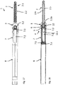
- the Figs. 1 to 4 show - as I said - a polyaxial configuration of the fastening device 1.
- This also has a polyaxial pressure element 9 ( Fig. 12-14 ) and this described pedicle screw 2 with a spherical screw head 2.3 ( Figures 15, 16 ) on.
- the polyaxial pressure element 9 ( Fig. 12-14 ) has a partially cylindrical recess 9.1 on its proximal side for partially embracing or receiving the rod 10, while a further hemispherical or dome-shaped recess 9.2 is provided on the distal end face of the pressure element 9 in order to grasp the spherical screw head 2.3 of the pedicle screw 2 .
- the pressure element 9, which is distal in relation to the rod 10, has a jacket 9.4 which tapers from its distal end to the proximal end, so that a gap 9.5 is formed between it and the inner wall of the tulip 3 (in particular Fig. 3 ).
- the pressure element 9 can assume a tilted orientation made possible by the described clamping device 4 of the rod 10 and be clamped in this, namely in an angular offset with respect to the orientation of the opposing elongated holes 3.2 in the walls of the tulip 3, i.e. also in an orientation tilted relative to the axis perpendicular.
- the clamping device 4 enables such tilted orientations of the rod 10 and does not hinder them.
- the partially cylindrical recess 9.1 has a larger radius of curvature than that in the Fig. 3 rod 10 shown. This results in a play 9.6 perpendicular to the extension of the rod 10 at the proximal opening of the pressure element 9 approximately halfway up the rod 10. This allows rods 10 with different diameters to be used in the same fastening device 1. If the rod shown has, for example, a diameter of 5.5 mm, as it is used and customary by most people and the cylindrical recess has a diameter of 6 mm, a rod with a diameter of 6 mm can also be used, for example, for strong, especially young people People, for whom a rod with a diameter of 5.5 mm often does not have the necessary strength.
- two opposite, recessed pressure surfaces 9.3 are provided in the distal area for transverse screws 3.5 that can be screwed in radially from the outside through the tulip 3 to fix the pressure element 9 inside the tulip 3.
- the polyaxial pedicle screw 2 itself is in the Figures 15 and 16 and has - as already stated above - the spherical pedicle screw head 2.3.
- the pedicle screw head 2.3 can be pivoted in all directions in the dome-shaped recess 9.2 on the distal area of the polyaxial pressure element 9.
- the screw head 2.3 and thus the pedicle screw 2 is held captively in the tulip 3 by means of the pressure element 9, since at its distal end 3.3 it has an opening that is narrower than the diameter of the screw head ( Fig. 1-4 ).
- a monoaxial device of the Fig. 17 In a monoaxial device of the Fig. 17
- the clamping device 4 with clamping screw 5 and rod clamp 6 is the same as in the previously described polyaxial fastening device. Only a - monoaxial - pedicle screw head 2.3a of the pedicle screw 2 and a - monoaxial - pressure element 9a, which are shown in an enlarged view in FIGS Figures 19-24 are shown.
- FIGS 17 to 19 show a monoaxial fastening device 1 in side view ( Fig. 17 ) or longitudinal section ( Fig. 18 , 19th ).
- the same parts and features are generally denoted by the same reference numerals as in the polyaxial configuration of FIG Figures 1 to 16 , which is also referred to. The different versions are explained below.
- the tulip 3 with the monoaxial pressure element 9 can be seen distal of the clamped transverse rod 10.
- the pressure element 9 holds the pedicle screw head 2.3a, while the pedicle screw 2 itself is screwed into a vertebral body and is fixed (not shown).
- Proximal of the transverse rod 10 the clamping screw 5 screwed in along the internal thread 7.1 of the tulip extension 7 in the screwing direction F and acting on the rod clamp 6 is located in the tulip 3 with the aid of a turning tool (not shown). This takes - here - a tilted position and can thus hold the transverse rod 10 vertically in a polyaxial extension direction.
- the monoaxial pressure element 9a like the polyaxial pressure element 9, has a proximal, partially cylindrical recess 9.1 for partially receiving the rod 10, but unlike the screw head 2.3a of the pedicle screw 2, a flat, frustoconical distal end face 9a.2 with a conical annular peripheral edge 9a.3 surrounding a central opening 9a.4 ( Figures 20-22 ).
- the inner wall of the tulip 3 has a step 3.7 and, proximally behind this, an enlargement 3.8 which tapers monoaxially in the proximal direction.
- the screw head 9a extends proximally up to this step 3.7 into the tulip 3.
- the - monoaxial - pressure element 9a begins distally only there and has a smaller diameter than the extension 3.8 at its distal end, so that there is a certain lateral play there and the monoaxial pressure element 9a in the tulip 3 can also be tilted slightly in order to achieve an eccentric alignment of the rod permitted by the clamping device 4, as shown in FIG Fig. 4 , is shown for the polyaxial device 1, not to hinder, but rather to accommodate and enable.
- the Fig. 22 shows the monoaxial pressure element 9a in a perspective view; the recess 9.1, which is wider than the transverse frame of the rod 10, allows the rod 10 to be fixed eccentrically.
- the pedicle screw 2 as in particular in the Fig. 18 , 23 and 24 is shown, has at its proximal end a - monoaxial pedicle screw head 2.3a, which can be pivoted accordingly.
- the screw head 2.3a has a cylindrical jacket 2.5 and a flat, proximal end-face recess 2.5a, which has an edge 2.6a which is also conical ring-shaped and is adapted to the peripheral edge 9a.3 ( Fig. 19 , 24 ).
- the illustrated pedicle screw 2 has a quadruple thread 2.2.1 in the proximal area of the screw shaft 2.1 over about a quarter of the length of the thread or screw shaft 2.1.
- Such a configuration can also be used for a polyaxial pedicle screw according to FIGS Figs. 1 to 4 , 15, 16 be provided.
Landscapes
- Health & Medical Sciences (AREA)
- Orthopedic Medicine & Surgery (AREA)
- Life Sciences & Earth Sciences (AREA)
- Surgery (AREA)
- Neurology (AREA)
- Heart & Thoracic Surgery (AREA)
- Engineering & Computer Science (AREA)
- Biomedical Technology (AREA)
- Nuclear Medicine, Radiotherapy & Molecular Imaging (AREA)
- Medical Informatics (AREA)
- Molecular Biology (AREA)
- Animal Behavior & Ethology (AREA)
- General Health & Medical Sciences (AREA)
- Public Health (AREA)
- Veterinary Medicine (AREA)
- Surgical Instruments (AREA)
- Farming Of Fish And Shellfish (AREA)
Claims (15)
- Dispositif (1) de fixation d'une tige sur un os, avec une vis pédiculaire (2), une tulipe (3) la maintenant, une vis de serrage (5), un serre-tige (6) pouvant pivoter par rapport à la vis de serrage (5), un élément de compression (9, 9a) disposé dans la tulipe (3) en vis-à-vis par rapport au serre-tige (6), caractérisé en ce que l'élément de compression (9, 9a) a une enveloppe se rétrécissant depuis son extrémité distale vers son extrémité proximale, de sorte qu'entre celle-ci et la paroi intérieure de la tulipe (3), une fente soit formée qui permette un basculement de l'élément de compression (9, 9a) à l'intérieur de la tulipe (3) par rapport à une position centrale réalisée dans le plan axial.
- Dispositif selon la revendication 1, caractérisé en ce que le serre-tige (6) peut être pivoté par rapport à la vis de serrage (5) via des zones sphériques (6.7, 5.9) bilatérales orientées de façon oblique par rapport à un axe principal (A) et orientées l'une vers l'autre.
- Dispositif selon la revendication 1 ou 2, caractérisé en ce que la vis de serrage (5) et le serre-tige (6) comportent des détourés arrière (5.6, 6.4) s'imbriquant l'un l'autre par l'arrière, le détouré arrière (5.6) de la vis de serrage (5) étant notamment formé par une saillie annulaire (5.5).
- Dispositif selon la revendication 3, caractérisé en ce que les détourés arrière (6.4) du serre-tige (6) sont formés par des doigts (6.2) élastiques disposés sur toute la périphérie, avec des becs (6.3).
- Dispositif selon l'une quelconque des revendications 3 ou 4, caractérisé en ce que les vis de serrage (5) comportent un cône intérieur (5.8) se rétrécissant dans la direction proximale à partir du détouré arrière (5.6).
- Dispositif selon la revendication 1 ou 2, caractérisé par la présence d'un adaptateur de serre-tige (6a) reliant la vis de serrage (5) et le serre-tige (6), le serre-tige (6) et l'adaptateur de serre-tige (6a) étant notamment soudés entre eux.
- Dispositif selon la revendication 6, caractérisé en ce que l'adaptateur de serre-tige (6a) est une partie annulaire avec des saillies proximales orientées vers l'extérieur dans le plan proximal qui s'engrènent avec du jeu dans les entailles radiales dans la vis de serrage (5), des saillies distales également orientées vers l'extérieur dans le plan radial, des saillies distales du serre-tige (6) également orientées vers l'extérieur dans le plan radial étant notamment prévues, ces saillies s'imbriquant dans les entailles radiales du serre-tige (6), le serre-tige (6) et l'adaptateur de serre-tige (6a) étant notamment soudés entre eux.
- Dispositif selon l'une quelconque des revendications précédentes, caractérisé en ce que le serre-tige (6) comporte sur son côté opposé à la vis de serrage (5) un évidement de serrage (6.5) en forme de cercle partiel et/ou que la vis de serrage (5) comporte un filetage de vis (5.2) asymétrique.
- Dispositif selon la revendication 8, caractérisé en ce qu'un flanc (5.4), orienté dans la direction de vissage à bloc (F) dans le plan proximal, du filetage (5.2) de la vis de serrage (5) s'étend selon un angle inférieur ou égal à 5°, notamment inférieur ou égal à 3°, jusqu'à un plan radial par rapport à l'axe de symétrie (S) de la vis de serrage (5).
- Dispositif selon la revendication 8, caractérisé en ce qu'un flanc (5.3), orienté distalement dans une direction de vissage à bloc (F), du filetage (5.2) de la vis de serrage (5) s'étend selon un angle différent de 90° par rapport à l'axe de symétrie (S) de la vis de serrage (5), de préférence de 30°, par rapport à un plan radial.
- Dispositif selon l'une quelconque des revendications précédentes, caractérisé en ce que la vis de serrage (5) comporte sur son côté opposé au serre-tige (6) un renfoncement (5.1) multiple ou non cylindrique.
- Dispositif selon l'une quelconque des revendications précédentes, caractérisé en ce que l'élément de compression (9, 9a) est disposé de façon à pouvoir basculer dans la tulipe (3).
- Dispositif selon la revendication 12, caractérisé en ce que le diamètre de l'élément de compression (9, 9a) est réduit au niveau d'au moins un de ses côtés avant par rapport au diamètre intérieur de la tulipe (3), de sorte que l'élément de compression (9, 9a) puisse basculer à l'intérieur de la tulipe (3).
- Dispositif selon l'une quelconque des revendications 12 ou 13, caractérisé en ce que l'élément de compression (9) de la tulipe (3) se rétrécit depuis son côté distal vers son côté avant, de façon à obtenir dans le plan proximal un jeu radial (9.6) entre la paroi intérieure de la tulipe (3) et l'enveloppe (9.4) de l'élément de compression (9) ou que la paroi intérieure de la tulipe (3) s'élargit depuis la hauteur du côté avant proximal jusqu'à la hauteur du côté avant distal de l'élément de compression (9a) en garantissant un jeu radial (9.6) entre l'élément de compression (9a) et la tulipe (3) jusqu'à atteindre la hauteur du côté avant distal de l'élément de compression (9a).
- Dispositif selon l'une quelconque des revendications précédentes, caractérisé en ce que la tige de vis (2.1) de la vis pédiculaire (2) comporte un double filetage (2.2), une zone proximale de la tige de vis (2.1) étant notamment réalisée sous la forme d'un quadruple filetage (2.2.1), de préférence sur une longueur d'un quart de la tige de vis pédiculaire (2.1).
Applications Claiming Priority (3)
| Application Number | Priority Date | Filing Date | Title |
|---|---|---|---|
| DE102015012909.0A DE102015012909A1 (de) | 2015-10-06 | 2015-10-06 | Vorrichtung zum Befestigen eines Stabs an einem Knochen |
| DE202016004114 | 2016-06-30 | ||
| PCT/EP2016/001479 WO2017059941A1 (fr) | 2015-10-06 | 2016-09-01 | Dispositif de fixation d'une tige sur un os |
Publications (2)
| Publication Number | Publication Date |
|---|---|
| EP3209229A1 EP3209229A1 (fr) | 2017-08-30 |
| EP3209229B1 true EP3209229B1 (fr) | 2021-07-28 |
Family
ID=56985578
Family Applications (1)
| Application Number | Title | Priority Date | Filing Date |
|---|---|---|---|
| EP16770206.7A Active EP3209229B1 (fr) | 2015-10-06 | 2016-09-01 | Dispositif de fixation d'une tige sur un os |
Country Status (8)
| Country | Link |
|---|---|
| US (1) | US10667846B2 (fr) |
| EP (1) | EP3209229B1 (fr) |
| JP (1) | JP6967290B2 (fr) |
| KR (1) | KR102612013B1 (fr) |
| CN (1) | CN108135640B (fr) |
| DE (1) | DE202016005347U1 (fr) |
| ES (1) | ES2891826T3 (fr) |
| WO (1) | WO2017059941A1 (fr) |
Families Citing this family (5)
| Publication number | Priority date | Publication date | Assignee | Title |
|---|---|---|---|---|
| US9980753B2 (en) * | 2009-06-15 | 2018-05-29 | Roger P Jackson | pivotal anchor with snap-in-place insert having rotation blocking extensions |
| JP2012529969A (ja) * | 2008-08-01 | 2012-11-29 | ロジャー・ピー・ジャクソン | スリーブ付き張力付与りコードを備える長手方向接続部材 |
| WO2012128825A1 (fr) * | 2011-03-24 | 2012-09-27 | Jackson Roger P | Ancrage osseux polyaxial avec articulation composée et tige enclipsable |
| US20220133360A1 (en) * | 2019-02-27 | 2022-05-05 | Lenkbar Llc | Spinal Fixation Assembly |
| DE102023126213B4 (de) * | 2023-09-27 | 2025-04-30 | SRH Wald-Klinikum Gera GmbH | Schraube zur Anordnung in einem Wirbelkörper einer Wirbelsäule |
Family Cites Families (21)
| Publication number | Priority date | Publication date | Assignee | Title |
|---|---|---|---|---|
| CH685850A5 (de) * | 1990-11-26 | 1995-10-31 | Synthes Ag | Verankerungseinrichtung |
| DE59301618D1 (de) * | 1992-06-04 | 1996-03-28 | Synthes Ag | Osteosynthetisches Befestigungselement |
| DE29710484U1 (de) * | 1997-06-16 | 1998-10-15 | Howmedica GmbH, 24232 Schönkirchen | Aufnahmeteil für ein Haltebauteil eines Wirbelsäulenimplantats |
| FR2829014B1 (fr) * | 2001-09-03 | 2005-04-08 | Stryker Spine | Systeme d'osteosynthese rachidienne comprenant un patin d'appui |
| US6692500B2 (en) * | 2001-10-15 | 2004-02-17 | Gary Jack Reed | Orthopedic stabilization device and method |
| US7766915B2 (en) * | 2004-02-27 | 2010-08-03 | Jackson Roger P | Dynamic fixation assemblies with inner core and outer coil-like member |
| US7951172B2 (en) | 2005-03-04 | 2011-05-31 | Depuy Spine Sarl | Constrained motion bone screw assembly |
| US7722651B2 (en) * | 2005-10-21 | 2010-05-25 | Depuy Spine, Inc. | Adjustable bone screw assembly |
| US8062340B2 (en) | 2006-08-16 | 2011-11-22 | Pioneer Surgical Technology, Inc. | Spinal rod anchor device and method |
| ES2453196T3 (es) * | 2006-08-24 | 2014-04-04 | Biedermann Technologies Gmbh & Co. Kg | Dispositivo de anclaje óseo |
| WO2008118295A2 (fr) * | 2007-03-26 | 2008-10-02 | Laszlo Garamszegi | Ensemble de vis pédiculaire à chargement par la partie inférieure |
| FR2925288B1 (fr) * | 2007-12-21 | 2010-01-15 | Michel Timoteo | Dispositif de connexion pivotant pour vis d'osteosynthese rachidienne |
| EP2355732B1 (fr) * | 2008-09-12 | 2015-07-29 | Synthes GmbH | Outil de réduction de tige pour la colonne vertébrale |
| CZ2010154A3 (cs) * | 2010-03-03 | 2011-09-14 | Šrámek@Jirí | Transpedikulární úhlove stabilní repozicní šroub s aretacním mechanismem uvnitr hlavy šroubu |
| US8961569B2 (en) * | 2010-10-04 | 2015-02-24 | Genesys Spine | Locking pedicle screw devices, methods, and systems |
| WO2012051576A2 (fr) | 2010-10-15 | 2012-04-19 | Phygen, Llc | Ensemble vis de fixation |
| CN202161400U (zh) * | 2011-07-26 | 2012-03-14 | 山东威高骨科材料有限公司 | 一种动态稳定椎弓根钉 |
| WO2013106217A1 (fr) * | 2012-01-10 | 2013-07-18 | Jackson, Roger, P. | Fermetures à départs multiples pour implants ouverts |
| US9358046B2 (en) * | 2012-12-31 | 2016-06-07 | Globus Medical, Inc. | Rod coupling system and devices and methods of making and using the same |
| US8852239B2 (en) * | 2013-02-15 | 2014-10-07 | Roger P Jackson | Sagittal angle screw with integral shank and receiver |
| US9968378B1 (en) * | 2015-07-22 | 2018-05-15 | University Of South Florida | Adaptation sphere saddle |
-
2016
- 2016-09-01 US US15/766,179 patent/US10667846B2/en active Active
- 2016-09-01 ES ES16770206T patent/ES2891826T3/es active Active
- 2016-09-01 DE DE202016005347.8U patent/DE202016005347U1/de not_active Expired - Lifetime
- 2016-09-01 CN CN201680058479.1A patent/CN108135640B/zh active Active
- 2016-09-01 KR KR1020187009464A patent/KR102612013B1/ko active Active
- 2016-09-01 WO PCT/EP2016/001479 patent/WO2017059941A1/fr not_active Ceased
- 2016-09-01 EP EP16770206.7A patent/EP3209229B1/fr active Active
- 2016-09-01 JP JP2018509574A patent/JP6967290B2/ja active Active
Non-Patent Citations (1)
| Title |
|---|
| None * |
Also Published As
| Publication number | Publication date |
|---|---|
| DE202016005347U1 (de) | 2016-10-07 |
| KR20180066068A (ko) | 2018-06-18 |
| ES2891826T3 (es) | 2022-01-31 |
| US10667846B2 (en) | 2020-06-02 |
| KR102612013B1 (ko) | 2023-12-12 |
| CN108135640A (zh) | 2018-06-08 |
| JP2018531638A (ja) | 2018-11-01 |
| CN108135640B (zh) | 2021-11-09 |
| EP3209229A1 (fr) | 2017-08-30 |
| JP6967290B2 (ja) | 2021-11-17 |
| US20180296250A1 (en) | 2018-10-18 |
| WO2017059941A1 (fr) | 2017-04-13 |
Similar Documents
| Publication | Publication Date | Title |
|---|---|---|
| EP3117787B1 (fr) | Vis pediculaire avec tulipe | |
| EP0671151B1 (fr) | Dispositif d'ostéosynthèse | |
| EP1274354B1 (fr) | Dispositif permettant la connexion articulee de deux corps | |
| EP1261288B1 (fr) | Element de connexion pour barres de stabilisation d'os ou de vertebres | |
| DE102005042766B4 (de) | Plattenloch einer Knochenplatte für die Osteosynthese | |
| EP1615598B1 (fr) | Dispositif de spondylodese | |
| EP1579816B1 (fr) | Elément d'ancrage et dispositif de stabilisation dynamique pour vertèbres ou os. | |
| EP0153546B1 (fr) | Fixation pour immobiliser des fragments d'os | |
| EP2802294B1 (fr) | Vis de verrouillage intramédullaire d'ostéosynthèse en chirurgie du pied pour la fixation de l'articulation basale du gros orteil | |
| EP3209229B1 (fr) | Dispositif de fixation d'une tige sur un os | |
| EP1545357B1 (fr) | Système pour l'ostéosynthèse | |
| EP2515779A1 (fr) | Système de plaques osseuses pour ostéosynthèse | |
| WO1999059492A1 (fr) | Implant osteosynthetique dote d'un assemblage articule encastre | |
| EP1460952A1 (fr) | Dispositif permettant de relier deux pieces a la maniere d'une articulation spherique | |
| EP1667592A1 (fr) | Element amortisseur | |
| EP2844169B1 (fr) | Système à plaque osseuse pour l'ostéosynthèse | |
| DE4330837A1 (de) | Pedikelschraube und Fixateur interne | |
| EP1935360A1 (fr) | Implant de plaque, en particulier pour l'application sur une colonne vertébrale, doté d'un système de fermeture à vis | |
| DE19945611B4 (de) | Proximaler Humerusnagel | |
| DE10328307A1 (de) | Wirbelkörperprothese | |
| DE4113083C2 (de) | Ringfixateur für die Osteosynthese | |
| DE202009012270U1 (de) | Knochenplattenverschraubung | |
| DE102005015496A1 (de) | Osteosyntheseimplantat mit Durchführung mit Gewinde | |
| DE102015012909A1 (de) | Vorrichtung zum Befestigen eines Stabs an einem Knochen | |
| DE4409242C2 (de) | Osteosynthesevorrichtung |
Legal Events
| Date | Code | Title | Description |
|---|---|---|---|
| STAA | Information on the status of an ep patent application or granted ep patent |
Free format text: STATUS: UNKNOWN |
|
| STAA | Information on the status of an ep patent application or granted ep patent |
Free format text: STATUS: THE INTERNATIONAL PUBLICATION HAS BEEN MADE |
|
| PUAI | Public reference made under article 153(3) epc to a published international application that has entered the european phase |
Free format text: ORIGINAL CODE: 0009012 |
|
| STAA | Information on the status of an ep patent application or granted ep patent |
Free format text: STATUS: REQUEST FOR EXAMINATION WAS MADE |
|
| 17P | Request for examination filed |
Effective date: 20170526 |
|
| AK | Designated contracting states |
Kind code of ref document: A1 Designated state(s): AL AT BE BG CH CY CZ DE DK EE ES FI FR GB GR HR HU IE IS IT LI LT LU LV MC MK MT NL NO PL PT RO RS SE SI SK SM TR |
|
| AX | Request for extension of the european patent |
Extension state: BA ME |
|
| DAV | Request for validation of the european patent (deleted) | ||
| DAX | Request for extension of the european patent (deleted) | ||
| STAA | Information on the status of an ep patent application or granted ep patent |
Free format text: STATUS: EXAMINATION IS IN PROGRESS |
|
| 17Q | First examination report despatched |
Effective date: 20201102 |
|
| GRAP | Despatch of communication of intention to grant a patent |
Free format text: ORIGINAL CODE: EPIDOSNIGR1 |
|
| STAA | Information on the status of an ep patent application or granted ep patent |
Free format text: STATUS: GRANT OF PATENT IS INTENDED |
|
| INTG | Intention to grant announced |
Effective date: 20210302 |
|
| GRAS | Grant fee paid |
Free format text: ORIGINAL CODE: EPIDOSNIGR3 |
|
| GRAA | (expected) grant |
Free format text: ORIGINAL CODE: 0009210 |
|
| STAA | Information on the status of an ep patent application or granted ep patent |
Free format text: STATUS: THE PATENT HAS BEEN GRANTED |
|
| AK | Designated contracting states |
Kind code of ref document: B1 Designated state(s): AL AT BE BG CH CY CZ DE DK EE ES FI FR GB GR HR HU IE IS IT LI LT LU LV MC MK MT NL NO PL PT RO RS SE SI SK SM TR |
|
| REG | Reference to a national code |
Ref country code: GB Ref legal event code: FG4D Free format text: NOT ENGLISH |
|
| REG | Reference to a national code |
Ref country code: CH Ref legal event code: EP |
|
| REG | Reference to a national code |
Ref country code: DE Ref legal event code: R096 Ref document number: 502016013505 Country of ref document: DE |
|
| REG | Reference to a national code |
Ref country code: AT Ref legal event code: REF Ref document number: 1413996 Country of ref document: AT Kind code of ref document: T Effective date: 20210815 |
|
| REG | Reference to a national code |
Ref country code: IE Ref legal event code: FG4D Free format text: LANGUAGE OF EP DOCUMENT: GERMAN |
|
| REG | Reference to a national code |
Ref country code: NL Ref legal event code: FP |
|
| REG | Reference to a national code |
Ref country code: SE Ref legal event code: TRGR |
|
| REG | Reference to a national code |
Ref country code: LT Ref legal event code: MG9D |
|
| PG25 | Lapsed in a contracting state [announced via postgrant information from national office to epo] |
Ref country code: RS Free format text: LAPSE BECAUSE OF FAILURE TO SUBMIT A TRANSLATION OF THE DESCRIPTION OR TO PAY THE FEE WITHIN THE PRESCRIBED TIME-LIMIT Effective date: 20210728 Ref country code: HR Free format text: LAPSE BECAUSE OF FAILURE TO SUBMIT A TRANSLATION OF THE DESCRIPTION OR TO PAY THE FEE WITHIN THE PRESCRIBED TIME-LIMIT Effective date: 20210728 Ref country code: FI Free format text: LAPSE BECAUSE OF FAILURE TO SUBMIT A TRANSLATION OF THE DESCRIPTION OR TO PAY THE FEE WITHIN THE PRESCRIBED TIME-LIMIT Effective date: 20210728 Ref country code: NO Free format text: LAPSE BECAUSE OF FAILURE TO SUBMIT A TRANSLATION OF THE DESCRIPTION OR TO PAY THE FEE WITHIN THE PRESCRIBED TIME-LIMIT Effective date: 20211028 Ref country code: PT Free format text: LAPSE BECAUSE OF FAILURE TO SUBMIT A TRANSLATION OF THE DESCRIPTION OR TO PAY THE FEE WITHIN THE PRESCRIBED TIME-LIMIT Effective date: 20211129 Ref country code: LT Free format text: LAPSE BECAUSE OF FAILURE TO SUBMIT A TRANSLATION OF THE DESCRIPTION OR TO PAY THE FEE WITHIN THE PRESCRIBED TIME-LIMIT Effective date: 20210728 Ref country code: BG Free format text: LAPSE BECAUSE OF FAILURE TO SUBMIT A TRANSLATION OF THE DESCRIPTION OR TO PAY THE FEE WITHIN THE PRESCRIBED TIME-LIMIT Effective date: 20211028 |
|
| REG | Reference to a national code |
Ref country code: ES Ref legal event code: FG2A Ref document number: 2891826 Country of ref document: ES Kind code of ref document: T3 Effective date: 20220131 |
|
| PG25 | Lapsed in a contracting state [announced via postgrant information from national office to epo] |
Ref country code: PL Free format text: LAPSE BECAUSE OF FAILURE TO SUBMIT A TRANSLATION OF THE DESCRIPTION OR TO PAY THE FEE WITHIN THE PRESCRIBED TIME-LIMIT Effective date: 20210728 Ref country code: LV Free format text: LAPSE BECAUSE OF FAILURE TO SUBMIT A TRANSLATION OF THE DESCRIPTION OR TO PAY THE FEE WITHIN THE PRESCRIBED TIME-LIMIT Effective date: 20210728 Ref country code: GR Free format text: LAPSE BECAUSE OF FAILURE TO SUBMIT A TRANSLATION OF THE DESCRIPTION OR TO PAY THE FEE WITHIN THE PRESCRIBED TIME-LIMIT Effective date: 20211029 |
|
| PG25 | Lapsed in a contracting state [announced via postgrant information from national office to epo] |
Ref country code: DK Free format text: LAPSE BECAUSE OF FAILURE TO SUBMIT A TRANSLATION OF THE DESCRIPTION OR TO PAY THE FEE WITHIN THE PRESCRIBED TIME-LIMIT Effective date: 20210728 |
|
| REG | Reference to a national code |
Ref country code: DE Ref legal event code: R097 Ref document number: 502016013505 Country of ref document: DE |
|
| PG25 | Lapsed in a contracting state [announced via postgrant information from national office to epo] |
Ref country code: SM Free format text: LAPSE BECAUSE OF FAILURE TO SUBMIT A TRANSLATION OF THE DESCRIPTION OR TO PAY THE FEE WITHIN THE PRESCRIBED TIME-LIMIT Effective date: 20210728 Ref country code: SK Free format text: LAPSE BECAUSE OF FAILURE TO SUBMIT A TRANSLATION OF THE DESCRIPTION OR TO PAY THE FEE WITHIN THE PRESCRIBED TIME-LIMIT Effective date: 20210728 Ref country code: RO Free format text: LAPSE BECAUSE OF FAILURE TO SUBMIT A TRANSLATION OF THE DESCRIPTION OR TO PAY THE FEE WITHIN THE PRESCRIBED TIME-LIMIT Effective date: 20210728 Ref country code: MC Free format text: LAPSE BECAUSE OF FAILURE TO SUBMIT A TRANSLATION OF THE DESCRIPTION OR TO PAY THE FEE WITHIN THE PRESCRIBED TIME-LIMIT Effective date: 20210728 Ref country code: EE Free format text: LAPSE BECAUSE OF FAILURE TO SUBMIT A TRANSLATION OF THE DESCRIPTION OR TO PAY THE FEE WITHIN THE PRESCRIBED TIME-LIMIT Effective date: 20210728 Ref country code: CZ Free format text: LAPSE BECAUSE OF FAILURE TO SUBMIT A TRANSLATION OF THE DESCRIPTION OR TO PAY THE FEE WITHIN THE PRESCRIBED TIME-LIMIT Effective date: 20210728 Ref country code: AL Free format text: LAPSE BECAUSE OF FAILURE TO SUBMIT A TRANSLATION OF THE DESCRIPTION OR TO PAY THE FEE WITHIN THE PRESCRIBED TIME-LIMIT Effective date: 20210728 |
|
| PLBE | No opposition filed within time limit |
Free format text: ORIGINAL CODE: 0009261 |
|
| STAA | Information on the status of an ep patent application or granted ep patent |
Free format text: STATUS: NO OPPOSITION FILED WITHIN TIME LIMIT |
|
| 26N | No opposition filed |
Effective date: 20220429 |
|
| PG25 | Lapsed in a contracting state [announced via postgrant information from national office to epo] |
Ref country code: LU Free format text: LAPSE BECAUSE OF NON-PAYMENT OF DUE FEES Effective date: 20210901 |
|
| PG25 | Lapsed in a contracting state [announced via postgrant information from national office to epo] |
Ref country code: HU Free format text: LAPSE BECAUSE OF FAILURE TO SUBMIT A TRANSLATION OF THE DESCRIPTION OR TO PAY THE FEE WITHIN THE PRESCRIBED TIME-LIMIT; INVALID AB INITIO Effective date: 20160901 |
|
| PG25 | Lapsed in a contracting state [announced via postgrant information from national office to epo] |
Ref country code: CY Free format text: LAPSE BECAUSE OF FAILURE TO SUBMIT A TRANSLATION OF THE DESCRIPTION OR TO PAY THE FEE WITHIN THE PRESCRIBED TIME-LIMIT Effective date: 20210728 |
|
| PG25 | Lapsed in a contracting state [announced via postgrant information from national office to epo] |
Ref country code: MK Free format text: LAPSE BECAUSE OF FAILURE TO SUBMIT A TRANSLATION OF THE DESCRIPTION OR TO PAY THE FEE WITHIN THE PRESCRIBED TIME-LIMIT Effective date: 20210728 |
|
| PG25 | Lapsed in a contracting state [announced via postgrant information from national office to epo] |
Ref country code: MT Free format text: LAPSE BECAUSE OF FAILURE TO SUBMIT A TRANSLATION OF THE DESCRIPTION OR TO PAY THE FEE WITHIN THE PRESCRIBED TIME-LIMIT Effective date: 20210728 |
|
| PGFP | Annual fee paid to national office [announced via postgrant information from national office to epo] |
Ref country code: IE Payment date: 20240919 Year of fee payment: 9 |
|
| PGFP | Annual fee paid to national office [announced via postgrant information from national office to epo] |
Ref country code: BE Payment date: 20240920 Year of fee payment: 9 |
|
| PGFP | Annual fee paid to national office [announced via postgrant information from national office to epo] |
Ref country code: NL Payment date: 20240920 Year of fee payment: 9 |
|
| PGFP | Annual fee paid to national office [announced via postgrant information from national office to epo] |
Ref country code: AT Payment date: 20240918 Year of fee payment: 9 |
|
| PGFP | Annual fee paid to national office [announced via postgrant information from national office to epo] |
Ref country code: SE Payment date: 20240923 Year of fee payment: 9 |
|
| PGFP | Annual fee paid to national office [announced via postgrant information from national office to epo] |
Ref country code: CH Payment date: 20241001 Year of fee payment: 9 |
|
| PGFP | Annual fee paid to national office [announced via postgrant information from national office to epo] |
Ref country code: DE Payment date: 20250918 Year of fee payment: 10 |
|
| PGFP | Annual fee paid to national office [announced via postgrant information from national office to epo] |
Ref country code: IT Payment date: 20250924 Year of fee payment: 10 |
|
| PGFP | Annual fee paid to national office [announced via postgrant information from national office to epo] |
Ref country code: GB Payment date: 20250929 Year of fee payment: 10 |
|
| PGFP | Annual fee paid to national office [announced via postgrant information from national office to epo] |
Ref country code: FR Payment date: 20250922 Year of fee payment: 10 |
|
| PG25 | Lapsed in a contracting state [announced via postgrant information from national office to epo] |
Ref country code: TR Free format text: LAPSE BECAUSE OF FAILURE TO SUBMIT A TRANSLATION OF THE DESCRIPTION OR TO PAY THE FEE WITHIN THE PRESCRIBED TIME-LIMIT Effective date: 20210728 |
|
| PGFP | Annual fee paid to national office [announced via postgrant information from national office to epo] |
Ref country code: ES Payment date: 20251020 Year of fee payment: 10 |