EP3211293B1 - Dispositif de dissipation thermique pour un dispositif lumineux d'un véhicule automobile - Google Patents
Dispositif de dissipation thermique pour un dispositif lumineux d'un véhicule automobile Download PDFInfo
- Publication number
- EP3211293B1 EP3211293B1 EP17156709.2A EP17156709A EP3211293B1 EP 3211293 B1 EP3211293 B1 EP 3211293B1 EP 17156709 A EP17156709 A EP 17156709A EP 3211293 B1 EP3211293 B1 EP 3211293B1
- Authority
- EP
- European Patent Office
- Prior art keywords
- printed circuit
- metal support
- crimping
- heat dissipation
- support
- Prior art date
- Legal status (The legal status is an assumption and is not a legal conclusion. Google has not performed a legal analysis and makes no representation as to the accuracy of the status listed.)
- Active
Links
Images
Classifications
-
- F—MECHANICAL ENGINEERING; LIGHTING; HEATING; WEAPONS; BLASTING
- F21—LIGHTING
- F21S—NON-PORTABLE LIGHTING DEVICES; SYSTEMS THEREOF; VEHICLE LIGHTING DEVICES SPECIALLY ADAPTED FOR VEHICLE EXTERIORS
- F21S45/00—Arrangements within vehicle lighting devices specially adapted for vehicle exteriors, for purposes other than emission or distribution of light
- F21S45/40—Cooling of lighting devices
- F21S45/47—Passive cooling, e.g. using fins, thermal conductive elements or openings
-
- F—MECHANICAL ENGINEERING; LIGHTING; HEATING; WEAPONS; BLASTING
- F21—LIGHTING
- F21S—NON-PORTABLE LIGHTING DEVICES; SYSTEMS THEREOF; VEHICLE LIGHTING DEVICES SPECIALLY ADAPTED FOR VEHICLE EXTERIORS
- F21S41/00—Illuminating devices specially adapted for vehicle exteriors, e.g. headlamps
- F21S41/10—Illuminating devices specially adapted for vehicle exteriors, e.g. headlamps characterised by the light source
- F21S41/19—Attachment of light sources or lamp holders
- F21S41/192—Details of lamp holders, terminals or connectors
-
- F—MECHANICAL ENGINEERING; LIGHTING; HEATING; WEAPONS; BLASTING
- F21—LIGHTING
- F21S—NON-PORTABLE LIGHTING DEVICES; SYSTEMS THEREOF; VEHICLE LIGHTING DEVICES SPECIALLY ADAPTED FOR VEHICLE EXTERIORS
- F21S45/00—Arrangements within vehicle lighting devices specially adapted for vehicle exteriors, for purposes other than emission or distribution of light
- F21S45/40—Cooling of lighting devices
- F21S45/49—Attachment of the cooling means
-
- F—MECHANICAL ENGINEERING; LIGHTING; HEATING; WEAPONS; BLASTING
- F21—LIGHTING
- F21S—NON-PORTABLE LIGHTING DEVICES; SYSTEMS THEREOF; VEHICLE LIGHTING DEVICES SPECIALLY ADAPTED FOR VEHICLE EXTERIORS
- F21S45/00—Arrangements within vehicle lighting devices specially adapted for vehicle exteriors, for purposes other than emission or distribution of light
- F21S45/50—Waterproofing
-
- F—MECHANICAL ENGINEERING; LIGHTING; HEATING; WEAPONS; BLASTING
- F21—LIGHTING
- F21V—FUNCTIONAL FEATURES OR DETAILS OF LIGHTING DEVICES OR SYSTEMS THEREOF; STRUCTURAL COMBINATIONS OF LIGHTING DEVICES WITH OTHER ARTICLES, NOT OTHERWISE PROVIDED FOR
- F21V17/00—Fastening of component parts of lighting devices, e.g. shades, globes, refractors, reflectors, filters, screens, grids or protective cages
- F21V17/10—Fastening of component parts of lighting devices, e.g. shades, globes, refractors, reflectors, filters, screens, grids or protective cages characterised by specific fastening means or way of fastening
- F21V17/14—Bayonet-type fastening
-
- F—MECHANICAL ENGINEERING; LIGHTING; HEATING; WEAPONS; BLASTING
- F21—LIGHTING
- F21V—FUNCTIONAL FEATURES OR DETAILS OF LIGHTING DEVICES OR SYSTEMS THEREOF; STRUCTURAL COMBINATIONS OF LIGHTING DEVICES WITH OTHER ARTICLES, NOT OTHERWISE PROVIDED FOR
- F21V19/00—Fastening of light sources or lamp holders
- F21V19/001—Fastening of light sources or lamp holders the light sources being semiconductors devices, e.g. LEDs
- F21V19/003—Fastening of light source holders, e.g. of circuit boards or substrates holding light sources
- F21V19/005—Fastening of light source holders, e.g. of circuit boards or substrates holding light sources by permanent fixing means, e.g. gluing, riveting or embedding in a potting compound
-
- F—MECHANICAL ENGINEERING; LIGHTING; HEATING; WEAPONS; BLASTING
- F21—LIGHTING
- F21V—FUNCTIONAL FEATURES OR DETAILS OF LIGHTING DEVICES OR SYSTEMS THEREOF; STRUCTURAL COMBINATIONS OF LIGHTING DEVICES WITH OTHER ARTICLES, NOT OTHERWISE PROVIDED FOR
- F21V29/00—Protecting lighting devices from thermal damage; Cooling or heating arrangements specially adapted for lighting devices or systems
- F21V29/50—Cooling arrangements
- F21V29/502—Cooling arrangements characterised by the adaptation for cooling of specific components
- F21V29/508—Cooling arrangements characterised by the adaptation for cooling of specific components of electrical circuits
-
- F—MECHANICAL ENGINEERING; LIGHTING; HEATING; WEAPONS; BLASTING
- F21—LIGHTING
- F21Y—INDEXING SCHEME ASSOCIATED WITH SUBCLASSES F21K, F21L, F21S and F21V, RELATING TO THE FORM OR THE KIND OF THE LIGHT SOURCES OR OF THE COLOUR OF THE LIGHT EMITTED
- F21Y2115/00—Light-generating elements of semiconductor light sources
- F21Y2115/10—Light-emitting diodes [LED]
Definitions
- the invention relates to the field of lighting and light signaling of motor vehicles.
- the invention relates to a luminous device for a vehicle comprising a heat dissipation device and its mechanical attachment to a printed circuit.
- LED is a semiconductor component, which, when traversed by an electric current of a predetermined intensity, emits light rays.
- a luminous flux of a predetermined intensity generally related to the intensity of the electric current passing through the LED, can then be measured.
- LED technology makes it possible on the one hand to reduce the electrical energy requirements of lighting and/or signaling devices, and on the other hand it allows vehicle manufacturers to create interesting and individual optical signatures.
- a plurality of LEDs can for example be arranged along a curvilinear outline.
- WO 2014/056834 A1 describes a known luminous device comprising a heat dissipation device on which a printed circuit is fixed.
- the LEDs are on a printed circuit which is advantageously connected to means for powering the LEDs.
- the circuit board is usually covered with a case.
- heat dissipation elements are fashioned from Aluminum, which is a relatively expensive material.
- the use of thick sheets with the aim of obtaining, by stamping, pins of an adequate height to hold a printed circuit therefore generates on the one hand a cost and on the other hand a significant weight.
- a significant sheet thickness is required in order to be able to extract a pin of adequate dimensions by stamping.
- the object of the invention is to overcome at least one of the problems posed by the prior art.
- the subject of the invention is a luminous device as defined in claim 1.
- the heat dissipation device comprises a metal support comprising at least one support portion of generally flat shape and at least one crimping pin intended to fix a printed circuit of the luminous device on said support.
- the heat dissipation device is remarkable in that said pin is fixed in a sealed manner to a first face of the support by brazing.
- the fixing of the pin is preferably carried out on the support portion of generally planar shape.
- the metal support is generally flat in shape.
- the metal support may have a thickness which is less than the height of the pin measured with respect to said first face of the support.
- the printed circuit may be of the molded printed circuit, MID (“moulded interconnect device”) type.
- the printed circuit may be of the flexible printed circuit type, FPCB (“Flexible Printed Circuit Board”).
- the pin may preferably have a length, corresponding to its height relative to the support to which it is fixed, which is greater than the thickness of the printed circuit that it is intended to fix to the support.
- the support can preferably have a thickness of less than 2.5 mm.
- the metal support may preferably be aluminum.
- the support and the pin can be made of identical materials.
- the support and the pin can be made of different metallic materials.
- Cooling fins can preferably be fixed to a second face of the support by brazing. Alternatively, cooling fins can be fixed to the first face of the support by brazing.
- a clearance is preserved between the peg and the face of the metal support, in order to avoid possible degradation of the solder during subsequent crimping of the peg.
- the crimping step comprises, according to the invention, a step of bringing at least one electrical track of the printed circuit into electrical contact with the crimping pin, in order to connect said electrical track to the electrical ground potential.
- the printed circuit may comprise at least one light source of the light device. It may for example be a light source with a semiconductor element such as a light emitting diode, LED.
- the printed circuit may alternatively comprise a circuit for controlling the supply of at least one light source of the light device.
- the numbers 100, 200 describe for example a dissipation device in two different embodiments in accordance with the invention.
- the brazing of metals is a permanent assembly process known per se in the state of the art, which makes it possible to establish a metallic continuity between the joined parts.
- the brazing mechanism is atomic diffusion/migration on either side of the edges to be joined, obtained by heat action. Unlike welding, the joined edges are not melted during the brazing process.
- brazing is carried out using a filler metal or a brazing product, the melting temperature of which is lower than that of the parts to be assembled.
- the choice of such a material is within the reach of those skilled in the art.
- an alloy of aluminum and silicon can for example be used as filler metal.
- the melting temperature of such an alloy is between 570°C and 625°C.
- the parts to be assembled can be made of different metals or of the same metal.
- the brazing temperature is lower than the melting temperature of the parts to be assembled, but higher than the melting temperature of the filler metal.
- Brazing makes it possible to produce tight joints between the assembled parts, the final assembly having metallurgical and thermal continuity.
- the assembly of multiple parts can also be carried out in parallel in a furnace.
- local heat input can be used to make a brazed joint.
- the parts to be assembled should preferably be clean and free of surface oxides, in order to guarantee the brazing effect.
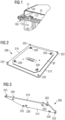
- FIG. 1 shows a thermal device 100 according to the invention for a light device of a motor vehicle.
- the light device further comprises a printed circuit 10 which supports a power supply control circuit for light sources, for example light-emitting diodes LED.
- the power supply control circuit generally involves a converter circuit and produces heat.
- the figure also shows a housing 12 which covers the printed circuit, and which makes a tight seal with the edge of the heat dissipation device.
- the printed circuit comprises an opening through which passes a crimping pin 120 fixed to a portion of the face 112 of the support 110 of the heat dissipation device, said surface portion being generally planar.
- the crimping pin is fixed to the support 110 by brazing. It is used to maintain the printed circuit in a predetermined position by the location of the pins and the corresponding openings of the printed circuit.
- the opposite face 114 of the support 110 can accommodate cooling fins 130 in order to increase the surface of the heat dissipation device which is in contact with the ambient air, thus facilitating the exchange of heat .
- the fins are advantageously fixed to the support 110 by brazing.
- a support 110 of a small thickness either less than 2.5 mm, less than 1.5 mm, or for example 1 mm.
- the height of the pins 120 on the side 112 is chosen independently of the thickness of the support or of the piece of aluminum sheet 110.
- the height of the pins 120 must be large enough for the pins to pass through the openings provided in the circuit printed and stand out to allow the fixing of the printed circuit by crimping the pins.
- the height of the pins 120 can for example be at least 2.5 mm relative to the face 112 of the support 110.
- the base thereof In order to be able to carry out the crimping, during which a significant mechanical stress is applied to the pin, the base thereof must be aligned with the plane of the support 110.
- FIG. 2 shows a preferred embodiment of the heat dissipation device 200 according to the invention.
- the face 212 which supports the printed circuit 20 is shown.
- Crimping pegs 220 have been attached to the generally planar support 210. These pegs are used to hold the printed circuit in a predetermined position, passing through openings in the printed circuit provided for this purpose, before being crimped.
- a second set of crimping pins 222 is provided to fix thereto a casing which can cover the printed circuit in a sealed manner.
- picture 3 shows the same embodiment as the figure 2 , however the opposite face 214 of device 200 is shown.
- the pegs 220, 222 in this embodiment pass through an opening in the support 210 and comprise a shoulder which rests on a face 214 of the support 210.
- This arrangement facilitates the alignment of the pegs with respect to the flat support 210. Pins having a shoulder at one end are inserted into the openings of the support 210 provided for this purpose until the shoulder comes into contact with the face 214. In this position the pins are oriented perpendicularly relative to the support and can be brazed to assemble the parts in question.
- the crimping of the pins can advantageously create electrical contact between the upper face of the printed circuit, which does not face the support 110, 210 of the device, and the heat dissipation device itself, which represents usually zero electric potential or ground.
- an electrical track of the circuit includes the edges of an opening in the printed circuit through which one of the crimping pins passes, this contact is used to connect the electrical track in question to ground potential.
Landscapes
- Engineering & Computer Science (AREA)
- General Engineering & Computer Science (AREA)
- Cooling Or The Like Of Semiconductors Or Solid State Devices (AREA)
- Cooling Or The Like Of Electrical Apparatus (AREA)
- Non-Portable Lighting Devices Or Systems Thereof (AREA)
- Arrangement Of Elements, Cooling, Sealing, Or The Like Of Lighting Devices (AREA)
Description
- L'invention a trait au domaine de l'éclairage et de la signalisation lumineuse des véhicules automobiles. En particulier, l'invention concerne un dispositif lumineux pour véhicule comprenant un dispositif de dissipation thermique et sa fixation mécanique à un circuit imprimé.
- Dans le domaine de l'éclairage et de la signalisation lumineuse des véhicules automobiles, il devient de plus en plus courant d'avoir recours à des sources lumineuses de type diode électroluminescente, LED. Une LED est un composant semi-conducteur, qui, lorsqu'il est parcouru par un courant électrique d'une intensité prédéterminée, émet des rayons lumineux. Un flux lumineux d'une intensité prédéterminée, généralement en rapport avec l'intensité du courant électrique qui traverse la LED, peut alors être mesuré. La technologie des LEDs permet d'une part de réduire les besoins d'énergie électrique des dispositifs d'éclairage et/ou de signalisation, et d'autre part elle permet aux constructeurs de véhicules de créer des signatures optiques intéressantes et individuelles. Une pluralité de LEDs peut par exemple être disposée le long d'un contour curviligne.
- Le document
WO 2014/056834 A1 décrit un dispositif lumineux connu comprenant un dispositif de dissipation thermique sur lequel un circuit imprimé est fixé. - Il est connu de disposer les LEDs sur un circuit imprimé qui est avantageusement relié à des moyens d'alimentation électrique des LEDs. Afin de protéger les composants du circuit imprimé, le circuit imprimé est généralement recouvert d'un boîtier. Pour pouvoir évacuer la chaleur produite lors du fonctionnement des LEDs, il est également connu de disposer le circuit imprimé qui les supporte, ou un circuit imprimé qui supporte un circuit de pilotage de l'alimentation électrique des LEDs, directement sur un élément dissipateur de chaleur, par exemple un radiateur métallique.
- Afin de fixer un circuit imprimé sur une plaque métallique d'un radiateur, il est connu de prévoir des ouvertures ou trous dans le substrat du circuit imprimé. Des pions sur la plaque métallique peuvent traverser les trous afin de maintenir le circuit imprimé dans une position prédéterminée. De manière connue, les pions sont venus de matière avec la plaque métallique du radiateur en question. Ceci est réalisé en utilisant un outil d'emboutissage qui permet de déformer la plaque pour en faire ressortir un pion. Evidemment, la hauteur d'un tel pion ne peut pas être supérieure à l'épaisseur de la plaque de laquelle le pion est ressorti par emboutissage. La hauteur du pion nécessaire à maintenir le circuit imprimé en position est dépendant de la hauteur du circuit imprimé. Elle peut par exemple être d'au moins 2,5 mm. Cette hauteur correspond donc à l'épaisseur minimale que la plaque métallique ou tôle doit présenter avant d'être emboutie. Typiquement, les éléments de dissipation de chaleur sont façonnés en Aluminium, qui est un matériel relativement coûteux. L'utilisation de tôles épaisses dans le but d'obtenir par emboutissage des pions d'une hauteur adéquate à la tenue d'un circuit imprimé engendre donc d'une part un coût et d'autre part un poids importants. Comme il est nécessaire d'obtenir un pion d'une hauteur plus grande que celle du circuit imprimé, il faut une épaisseur de tôle importante pour en pouvoir sortir un pion de dimensions adéquates par emboutissage.
- L'invention a pour objectif de pallier à au moins un des problèmes posés par l'art antérieur.
- L'invention a pour objet un dispositif lumineux tel que défini dans la revendication 1. Le dispositif de dissipation thermique comprend un support métallique comprenant au moins une portion de support de forme généralement plane et au moins un pion de sertissage destiné à fixer un circuit imprimé du dispositif lumineux sur ledit support. Le dispositif de dissipation thermique est remarquable en ce que ledit pion est fixé de manière étanche sur une première face du support par brasage.
- La fixation du pion est de préférence réalisée sur la portion de support de forme généralement plane.
- Selon l'invention, le support métallique est de forme généralement plane.
- De préférence, le support métallique peut avoir une épaisseur qui est inférieure à la hauteur du pion mesurée par rapport à ladite première face du support.
- Le circuit imprimé peut être du type circuit imprimé moule, MID (« moulded interconnect device »).
- Le circuit imprimé peut être du type circuit imprimé flexible, FPCB (« Flexible Printed Circuit Board »).
- Le pion peut de préférence avoir une longueur, correspondant à sa hauteur par rapport au support auquel il est fixé, qui est supérieure à l'épaisseur du circuit imprimé qu'il est destiné à fixer au support.
- Le support peut de préférence avoir une épaisseur inférieure à 2.5 mm.
- Le support métallique peut de préférence être en en aluminium.
- De préférence, le support et le pion peuvent être en matériaux identiques. De manière alternative, le support et le pion peuvent être en matériaux métalliques différents.
- Des ailettes de refroidissement peuvent de préférence être fixées sur une deuxième face du support par brasage. Alternativement, des ailettes de refroidissement peuvent être fixées sur la première face du support par brasage.
- De préférence, la fixation d'au moins un pion de sertissage destiné à fixer un circuit imprimé d'un dispositif lumineux d'un véhicule automobile sur un support métallique se fait par un procédé qui comprend les étapes suivantes :
- alignement de manière généralement parallèle de la surface de base du pion avec une face du support métallique ;
- apport d'un matériau de brasage entre la base du pion et la face du support métallique ;
- brasage à une température inférieure aux températures de fusion du pion et du support métallique.
- De préférence, lors de l'étape d'alignement un jeu est préservé entre le pion et la face du support métallique, afin d'éviter une dégradation éventuelle de la brasure lors d'un sertissage ultérieur du pion.
- L'invention a pour objet un procédé d'assemblage selon la revendication 7. Le procédé d'assemblage comprend les étapes suivantes :
- alignement d'au moins une ouverture dans le support du circuit imprimé par rapport à au moins un pion de sertissage du dispositif de dissipation thermique ;
- pose du circuit imprimé sur le support du dispositif de dissipation thermique, de façon à ce que le pion de sertissage passe à travers ladite ouverture ;
- sertissage du pion pour fixer le circuit imprimé sur le dispositif de dissipation thermique.
- L'étape de sertissage comprend, selon l'invention, une étape de mise en contact électrique d'au moins une piste électrique du circuit imprimé avec le pion de sertissage, afin de relier ladite piste électrique au potentiel électrique de masse.
- De préférence, le circuit imprimé peut comprendre au moins une source lumineuse du dispositif lumineux. Il peut par exemple s'agir d'une source lumineuse à élément semiconducteur telle qu'une diode électroluminescente, LED. Le circuit imprimé peut alternativement comprendre un circuit de pilotage de l'alimentation d'au moins une source lumineuse du dispositif lumineux.
- En utilisant les mesures de l'invention, il devient possible proposer des solutions de fixation d'un circuit imprimé sur une plaque métallique d'un élément dissipateur de chaleur, qui engendrent des tôles amincies par rapport aux solutions connues dans l'état de l'art. En fixant des pions de sertissage à une tôle mince par brasage, il est possible de proposer des pions dont la hauteur est indépendante de l'épaisseur de la tôle, tout en maintenant l'étanchéité du joint entre le pion et la tôle. Il en résulte une réduction conséquente de l'épaisseur de la tôle, ce qui engendre des gains en termes de poids et de coûts. En plus, la fixation par sertissage permet une reprise du potentiel de masse par un circuit électrique du circuit imprimé.
- D'autres caractéristiques et avantages de la présente invention seront mieux compris à l'aide de la description exemplaire et des dessins parmi lesquels :
- la
figure 1 est une illustration schématique en perspective d'une coupe latérale à travers un composant d'un dispositif lumineux pour un véhicule automobile, comprenant un dispositif selon l'invention dans un mode de réalisation préférentiel; - la
figure 2 est une illustration schématique en perspective d'un mode de réalisation préférentiel du dispositif selon l'invention vu d'une première face, montrant également un circuit imprimé; - la
figure 3 est une illustration schématique en perspective d'un mode de réalisation préférentiel du dispositif selon l'invention vu d'une deuxième face, du côté opposé à la face illustrée par lafigure 2 . - Dans la description qui suit, des numéros de référence similaires seront utilisés pour décrire des concepts similaires à travers des modes de réalisation différents de l'invention. Ainsi, les numéros 100, 200 décrivent par exemple un dispositif de dissipation dans deux modes de réalisation différents conformes à l'invention.
- Sauf indication spécifique du contraire, des caractéristiques techniques décrites en détails pour un mode de réalisation donné peuvent être combinés aux caractéristiques techniques décrites dans le contexte d'autres modes de réalisation décrits à titre exemplaire et non limitatif.
- Le brasage des métaux est un procédé d'assemblage permanent connu en soi dans l'état de l'art, qui permet établir une continuité métallique entre les pièces réunies. Le mécanisme du brasage est la diffusion /migration atomique de part et d'autre des bords à assembler, obtenue par action calorique. Contrairement au soudage, les bords assemblés ne sont pas fondus lors du procédé de brasage. Typiquement, le brasage est réalisé à l'aide d'un métal d'apport ou d'un produit de brasage, dont la température de fusion est inférieure à celle des pièces à assembler. Le choix d'un tel matériau est à la portée de l'homme du métier. Pour le brasage de pièces en Aluminium, un alliage d'Aluminium et de Silicium peut par exemple être utilisé comme métal d'apport. La température de fusion d'un tel alliage se situe entre 570°C et 625 °C. Les pièces à assembler peuvent être constitués de métaux différents ou d'un même métal. La température de brasage est inférieure à la température de fusion des pièces à assembler, mais supérieure à la température de fusion du métal d'apport.
- Le brasage permet de réaliser des joints étanches entre les pièces assemblées, l'assemblage final présentant une continuité métallurgique et thermique. L'assemblage de pièces multiples peut en outre être réalisé en parallèle dans un four. Alternativement, un apport calorifique local peut être utilisé pour réaliser un assemblage par brasage. De manière connue, les pièces à assembler doivent de préférence être propres et dépourvues d'oxydes en surface, afin de garantir l'effet de brasage.
- La
figure 1 montre un dispositif thermique 100 selon l'invention pour un dispositif lumineux d'un véhicule automobile. Le dispositif lumineux comprend en outre un circuit imprimé 10 qui supporte un circuit de pilotage de l'alimentation de sources lumineuses, par exemple de diodes électroluminescentes LED. Le circuit de pilotage de l'alimentation fait en général intervenir un circuit convertisseur et produit de la chaleur. La figure montre également un boîtier 12 qui recouvre le circuit imprimé, et qui réalise un joint étanche avec le bord du dispositif de dissipation thermique. Le circuit imprimé comprend une ouverture à travers de laquelle passe un pion de sertissage 120 fixé sur une portion de la face 112 du support 110 du dispositif de dissipation thermique, ladite portion de surface étant généralement plane. Le pion de sertissage est fixé au support 110 par brasage. Il sert à maintenir le circuit imprimé dans une position prédéterminée par l'emplacement du/des pions et des ouvertures correspondantes du circuit imprimé. - Comme indiqué sur la
figure 1 , la face opposée 114 du support 110, ou alternativement la face 112, peut héberger des ailettes de refroidissement 130 afin d'augmenter la surface du dispositif de dissipation thermique qui est au contact avec l'air ambiant, facilitant ainsi l'échange de chaleur. Les ailettes sont avantageusement fixées au support 110 par brasage. - Afin de faciliter l'échange thermique de la première face 112 qui dans l'exemple montré supporte la source de chaleur, vers la deuxième face 114 qui supporte les ailettes de refroidissement, il est avantageux de prévoir un support 110 d'une épaisseur faible, soit inférieure à 2.5 mm, inférieure à 1.5 mm, ou par exemple de 1 mm. La hauteur des pions 120 du côté 112 est choisie de manière indépendante de l'épaisseur du support ou du morceau de tôle en Aluminium 110. La hauteur des pions 120 doit être suffisamment importante pour que les pions passent à travers les ouvertures prévues dans le circuit imprimé et ressortent pour permettre la fixation du circuit imprimé par sertissage des pions. La hauteur des pions 120 peut par exemple être d'au moins 2.5 mm par rapport à la face 112 du support 110. Afin de pouvoir réaliser le sertissage, lors duquel une importante contrainte mécanique est appliquée sur le pion, la base de celui-ci doit être alignée au plan du support 110.
- La
figure 2 montre un mode de réalisation préférentiel du dispositif de dissipation thermique 200 selon l'invention. La face 212 qui supporte le circuit imprimé 20 est montrée. Des pions de sertissage 220 ont été fixés au support généralement plan 210. Ces pions servent à maintenir le circuit imprimé dans une position prédéterminée, en passant par des ouvertures du circuit imprimé prévues à cet effet, avant d'être sertis. Dans ce mode de réalisation, un deuxième jeu de pions de sertissage 222 est prévu pour y fixer un boîtier qui peut recouvrir le circuit imprimé de manière étanche. Lafigure 3 montre le même mode de réalisation que lafigure 2 , cependant la face opposée 214 du dispositif 200 est illustrée. Il y est apparent que les pions 220, 222 dans ce mode de réalisation traversent une ouverture dans le support 210 et comprennent une épaule qui vient s'appuyer sur a face 214 du support 210. Cet arrangement facilite l'alignement des pions par rapport au support plan 210. Des pions ayant un épaulement à une extrémité sont insérés dans les ouvertures du support 210 prévues à cet effet jusqu'à ce que l'épaulement vienne en contact avec la face 214. Dans cette position les pions sont orientés de manière perpendiculaire par rapport au support et peuvent être brasés pour réaliser l'assemblage des pièces en question. - Il va de soi que la forme et les dimensions des pions et/ou du support du dispositif de dissipation thermique peuvent être adaptées selon les besoins d'une application spécifique visée sans pour autant sortir du cadre de la présente invention.
- Dans tous les modes de réalisation, le sertissage des pions peut avantageusement créer un contact électrique entre la face supérieure du circuit imprimé, qui ne fait pas face au support 110, 210 du dispositif, et le dispositif de dissipation thermique lui-même, qui représente en général le potentiel électrique zéro ou la masse. Lorsqu'une piste électrique du circuit comprend les bords d'une ouverture du circuit imprimé par laquelle un des pions de sertissage passe, ce contact sert à relier la piste électrique en question au potentiel de la masse.
Claims (7)
- Dispositif lumineux pour véhicule automobile comprenant :- un circuit imprimé (10) qui supporte un circuit de pilotage de l'alimentation de sources lumineuses ; et- un dispositif de dissipation thermique (100,200) comprenant :• un support métallique (110,210) comprenant au moins une portion de support de forme généralement plane ; et• au moins un pion de sertissage (120,220) étant fixé sur une première face (112,212) du support métallique (110,210)caractérisé en ce que le pion de sertissage (120, 220) est fixé par brasage de manière à réaliser un joint étanche entre le pion de sertissage (120, 220) et le support métallique (110, 210) ; eten ce que le circuit imprimé (10,20) est fixé sur le support métallique (110,210) par l'intermédiaire du pion de sertissage (120,220).
- Dispositif lumineux selon la revendication 1, caractérisé en ce que le support métallique (110,210) a une épaisseur qui est inférieure à la hauteur du pion de sertissage (120,220) mesurée par rapport à ladite première face (112,212) du support métallique (110,210).
- Dispositif lumineux selon une des revendications 1 ou 2, caractérisé en ce que le support métallique (110,210) a une épaisseur inférieure à 2.5 mm.
- Dispositif lumineux selon une des revendications 1 à 3, caractérisé en ce que le support métallique (110,210) est en aluminium.
- Dispositif lumineux selon une des revendications 1 à 4, caractérisé en ce que le support métallique (110,210) et le pion de sertissage (120,220) sont en matériaux identiques.
- Dispositif lumineux selon une des revendications 1 à 5, caractérisé en ce que des ailettes de refroidissement (130) sont fixées sur une deuxième face (114) du support métallique (110,210) par brasage.
- Procédé d'assemblage du circuit imprimé (10,20) sur le dispositif de dissipation thermique (100,200) du dispositif lumineux pour véhicule automobile selon une des revendications 1 à 6, caractérisé en ce que le procédé comprend les étapes suivantes :- alignement d'au moins une ouverture du circuit imprimé (10,20) par rapport à au moins un pion de sertissage (120,220) du dispositif de dissipation thermique (100,200) ;- pose du circuit imprimé (10,20) sur le support métallique (110,210) du dispositif de dissipation thermique (100,200), de façon à ce que le pion de sertissage (120,220) passe à travers ladite ouverture ;- sertissage (120,220) du pion pour fixer le circuit imprimé (10,20) sur le dispositif de dissipation thermique (100,200), l'étape de sertissage (120,220) comprenant l'étape de mise en contact électrique d'au moins une piste électrique du circuit imprimé (10,20) avec le pion de sertissage (120,220), afin de relier ladite piste électrique au potentiel électrique de masse.
Applications Claiming Priority (1)
| Application Number | Priority Date | Filing Date | Title |
|---|---|---|---|
| FR1651471A FR3048062B1 (fr) | 2016-02-23 | 2016-02-23 | Dispositif de dissipation thermique pour un dispositif lumineux d'un vehicule automobile |
Publications (2)
| Publication Number | Publication Date |
|---|---|
| EP3211293A1 EP3211293A1 (fr) | 2017-08-30 |
| EP3211293B1 true EP3211293B1 (fr) | 2023-04-05 |
Family
ID=55953251
Family Applications (1)
| Application Number | Title | Priority Date | Filing Date |
|---|---|---|---|
| EP17156709.2A Active EP3211293B1 (fr) | 2016-02-23 | 2017-02-17 | Dispositif de dissipation thermique pour un dispositif lumineux d'un véhicule automobile |
Country Status (4)
| Country | Link |
|---|---|
| US (1) | US20170241618A1 (fr) |
| EP (1) | EP3211293B1 (fr) |
| CN (1) | CN107101179B (fr) |
| FR (1) | FR3048062B1 (fr) |
Families Citing this family (4)
| Publication number | Priority date | Publication date | Assignee | Title |
|---|---|---|---|---|
| FR3074881B1 (fr) * | 2017-12-07 | 2025-08-01 | Valeo Vision | Module lumineux pour vehicule automobile |
| DE102018009292A1 (de) | 2018-11-26 | 2020-05-28 | Harting Ag | Elektrooptische Baugruppe mit Wärmeabführung sowie Verfahren zur Herstellung einer solchen Baugruppe |
| FR3104678B1 (fr) | 2019-12-11 | 2021-12-10 | Valeo Vision | Dispositif lumineux d’un véhicule automobile |
| CN119713177A (zh) * | 2023-09-28 | 2025-03-28 | 市光法雷奥(佛山)汽车照明系统有限公司 | 出光模块、车灯组件和机动车辆 |
Family Cites Families (15)
| Publication number | Priority date | Publication date | Assignee | Title |
|---|---|---|---|---|
| US5676305A (en) * | 1996-04-18 | 1997-10-14 | Motorola, Inc. | Method to achieve regulated force contact in pin transfer deposition of liquidus substances |
| US6749105B2 (en) * | 2002-03-21 | 2004-06-15 | Motorola, Inc. | Method and apparatus for securing a metallic substrate to a metallic housing |
| JP2006128652A (ja) * | 2004-09-29 | 2006-05-18 | Furukawa Electric Co Ltd:The | 発光部品搭載フラットケーブルの固定構造 |
| DE102007002838A1 (de) * | 2006-09-08 | 2008-03-27 | Robert Bosch Gmbh | LED-Modul mit Montagemittel umfassenden Kühlkörpern |
| CN201215138Y (zh) * | 2008-04-28 | 2009-04-01 | 江苏希西维轴承有限公司 | 无油自润滑轴承 |
| CN101530947B (zh) * | 2009-04-08 | 2012-07-04 | 西安交通大学 | 一种搅拌摩擦钎焊制备双金属复合板的方法 |
| CN101907909A (zh) * | 2009-06-05 | 2010-12-08 | 鸿富锦精密工业(深圳)有限公司 | 具有固定孔的主板 |
| JP5054148B2 (ja) * | 2010-04-14 | 2012-10-24 | 株式会社日本自動車部品総合研究所 | 車両用前照灯 |
| KR101823677B1 (ko) * | 2011-04-21 | 2018-01-30 | 엘지이노텍 주식회사 | 엘이디 조명장치 |
| KR102172743B1 (ko) * | 2012-05-29 | 2020-11-02 | 이치코 고교가부시키가이샤 | 차량용 등기구의 반도체형 광원의 광원 유닛, 차량용 등기구 |
| DE102012218538A1 (de) * | 2012-10-11 | 2014-04-17 | Arnold & Richter Cine Technik Gmbh & Co. Betriebs Kg | Verfahren zur Herstellung einer Lichterzeugungseinheit |
| CN202905712U (zh) * | 2012-10-16 | 2013-04-24 | 孔明 | 一种具有金属隔板的焊接板 |
| US9153886B2 (en) * | 2012-10-26 | 2015-10-06 | Continental Automotive Systems, Inc. | Pin header assembly and method of forming the same |
| FR3004787B1 (fr) * | 2013-04-19 | 2017-09-08 | Valeo Vision | Organe de refroidissement et dispositif d'eclairage ou de signalisation de vehicule automobile comprenant un tel organe |
| FR3022867B1 (fr) * | 2014-06-30 | 2016-07-15 | Valeo Vision | Dispositif lumineux pour vehicule automobile a moyens d'assemblage perfectionnes |
-
2016
- 2016-02-23 FR FR1651471A patent/FR3048062B1/fr active Active
-
2017
- 2017-02-17 EP EP17156709.2A patent/EP3211293B1/fr active Active
- 2017-02-21 CN CN201710093057.4A patent/CN107101179B/zh active Active
- 2017-02-23 US US15/440,174 patent/US20170241618A1/en not_active Abandoned
Also Published As
| Publication number | Publication date |
|---|---|
| CN107101179B (zh) | 2021-12-03 |
| EP3211293A1 (fr) | 2017-08-30 |
| CN107101179A (zh) | 2017-08-29 |
| FR3048062A1 (fr) | 2017-08-25 |
| FR3048062B1 (fr) | 2018-03-09 |
| US20170241618A1 (en) | 2017-08-24 |
Similar Documents
| Publication | Publication Date | Title |
|---|---|---|
| EP2306599B1 (fr) | Support pour source lumineuse de module d'éclairage | |
| EP3211293B1 (fr) | Dispositif de dissipation thermique pour un dispositif lumineux d'un véhicule automobile | |
| EP3073180B1 (fr) | Support de led avec surface de réception et connexion électrique par pontage | |
| EP1860707B1 (fr) | Composant de dissipation thermique et dispositif d'éclairage et/ou de signalisation à diode équipé d'un tel composant | |
| EP1981315B1 (fr) | Support électronique flexible équipé, supportant au moins une diode électroluminescente, et projecteur de véhicule automobile associé | |
| EP3002511B1 (fr) | Dispositif à composant semi-conducteur monté sur un dissipateur de chaleur, procédé de montage, et dispositif d'éclairage pour véhicule automobile comportant un tel dispositif | |
| FR3048153B1 (fr) | Module lumineux pour un vehicule automobile avec reprise de masse | |
| FR2994788A1 (fr) | Module d'eclairage comprenant un dispositif de commande maintenu de maniere amovible sur un support | |
| FR3041080A1 (fr) | Dispositif de dissipation thermique pour un module lumineux de vehicule automobile | |
| EP2730837A1 (fr) | Module d'éclairage avec des dissipateurs distincts fixés sur la même carte de circuit imprimé | |
| FR3055401A1 (fr) | Module lumineux de vehicule automobile a organe de refroidissement | |
| FR3026226A1 (fr) | Plaque de circuit | |
| FR2862424A1 (fr) | Dispositif de refroidissement d'un composant electrique et procede de fabrication de ce dispositif | |
| FR2923286A3 (fr) | Dispositif d'eclairage | |
| FR3041211A1 (fr) | Dispositif de pilotage de l’alimentation electrique d’une source lumineuse pour un dispositif d’eclairage de vehicule automobile | |
| EP3270040B1 (fr) | Module lumineux pour vehicule automobile | |
| EP4062259A1 (fr) | Calculateur embarqué avec interposeur sur la puce microprocesseur | |
| WO2015044359A1 (fr) | Fixation d'une optique secondaire sur un récepteur photovoltaïque | |
| FR3065114A1 (fr) | Dispositif electrique et procede d'assemblage du dispositif electrique | |
| FR3082920A1 (fr) | Module optique comprenant une carte electronique avec une puce electronique | |
| FR3137439A1 (fr) | Dispositif de signalisation de véhicule automobile | |
| WO2020053190A1 (fr) | Système lumineux pour véhicule | |
| FR3093397A1 (fr) | Boitier de module électronique avec organe de de dissipation thermique. | |
| FR2841729A3 (fr) | Agencement avec composants electriques | |
| FR3085739A1 (fr) | Module lumineux pour projecteur de vehicule automobile |
Legal Events
| Date | Code | Title | Description |
|---|---|---|---|
| PUAI | Public reference made under article 153(3) epc to a published international application that has entered the european phase |
Free format text: ORIGINAL CODE: 0009012 |
|
| STAA | Information on the status of an ep patent application or granted ep patent |
Free format text: STATUS: THE APPLICATION HAS BEEN PUBLISHED |
|
| AK | Designated contracting states |
Kind code of ref document: A1 Designated state(s): AL AT BE BG CH CY CZ DE DK EE ES FI FR GB GR HR HU IE IS IT LI LT LU LV MC MK MT NL NO PL PT RO RS SE SI SK SM TR |
|
| AX | Request for extension of the european patent |
Extension state: BA ME |
|
| STAA | Information on the status of an ep patent application or granted ep patent |
Free format text: STATUS: REQUEST FOR EXAMINATION WAS MADE |
|
| 17P | Request for examination filed |
Effective date: 20180221 |
|
| RBV | Designated contracting states (corrected) |
Designated state(s): AL AT BE BG CH CY CZ DE DK EE ES FI FR GB GR HR HU IE IS IT LI LT LU LV MC MK MT NL NO PL PT RO RS SE SI SK SM TR |
|
| STAA | Information on the status of an ep patent application or granted ep patent |
Free format text: STATUS: EXAMINATION IS IN PROGRESS |
|
| 17Q | First examination report despatched |
Effective date: 20210426 |
|
| REG | Reference to a national code |
Ref country code: DE Ref legal event code: R079 Ref document number: 602017067374 Country of ref document: DE Free format text: PREVIOUS MAIN CLASS: F21S0008100000 Ipc: F21S0045500000 |
|
| GRAP | Despatch of communication of intention to grant a patent |
Free format text: ORIGINAL CODE: EPIDOSNIGR1 |
|
| STAA | Information on the status of an ep patent application or granted ep patent |
Free format text: STATUS: GRANT OF PATENT IS INTENDED |
|
| RIC1 | Information provided on ipc code assigned before grant |
Ipc: F21S 45/49 20180101ALI20220920BHEP Ipc: F21S 45/47 20180101ALI20220920BHEP Ipc: F21S 41/19 20180101ALI20220920BHEP Ipc: F21S 45/50 20180101AFI20220920BHEP |
|
| INTG | Intention to grant announced |
Effective date: 20221021 |
|
| GRAS | Grant fee paid |
Free format text: ORIGINAL CODE: EPIDOSNIGR3 |
|
| GRAA | (expected) grant |
Free format text: ORIGINAL CODE: 0009210 |
|
| STAA | Information on the status of an ep patent application or granted ep patent |
Free format text: STATUS: THE PATENT HAS BEEN GRANTED |
|
| AK | Designated contracting states |
Kind code of ref document: B1 Designated state(s): AL AT BE BG CH CY CZ DE DK EE ES FI FR GB GR HR HU IE IS IT LI LT LU LV MC MK MT NL NO PL PT RO RS SE SI SK SM TR |
|
| REG | Reference to a national code |
Ref country code: GB Ref legal event code: FG4D Free format text: NOT ENGLISH |
|
| REG | Reference to a national code |
Ref country code: CH Ref legal event code: EP |
|
| REG | Reference to a national code |
Ref country code: AT Ref legal event code: REF Ref document number: 1558485 Country of ref document: AT Kind code of ref document: T Effective date: 20230415 |
|
| REG | Reference to a national code |
Ref country code: DE Ref legal event code: R096 Ref document number: 602017067374 Country of ref document: DE |
|
| REG | Reference to a national code |
Ref country code: IE Ref legal event code: FG4D Free format text: LANGUAGE OF EP DOCUMENT: FRENCH |
|
| P01 | Opt-out of the competence of the unified patent court (upc) registered |
Effective date: 20230528 |
|
| REG | Reference to a national code |
Ref country code: LT Ref legal event code: MG9D |
|
| REG | Reference to a national code |
Ref country code: NL Ref legal event code: MP Effective date: 20230405 |
|
| REG | Reference to a national code |
Ref country code: AT Ref legal event code: MK05 Ref document number: 1558485 Country of ref document: AT Kind code of ref document: T Effective date: 20230405 |
|
| PG25 | Lapsed in a contracting state [announced via postgrant information from national office to epo] |
Ref country code: NL Free format text: LAPSE BECAUSE OF FAILURE TO SUBMIT A TRANSLATION OF THE DESCRIPTION OR TO PAY THE FEE WITHIN THE PRESCRIBED TIME-LIMIT Effective date: 20230405 |
|
| PG25 | Lapsed in a contracting state [announced via postgrant information from national office to epo] |
Ref country code: SE Free format text: LAPSE BECAUSE OF FAILURE TO SUBMIT A TRANSLATION OF THE DESCRIPTION OR TO PAY THE FEE WITHIN THE PRESCRIBED TIME-LIMIT Effective date: 20230405 Ref country code: PT Free format text: LAPSE BECAUSE OF FAILURE TO SUBMIT A TRANSLATION OF THE DESCRIPTION OR TO PAY THE FEE WITHIN THE PRESCRIBED TIME-LIMIT Effective date: 20230807 Ref country code: NO Free format text: LAPSE BECAUSE OF FAILURE TO SUBMIT A TRANSLATION OF THE DESCRIPTION OR TO PAY THE FEE WITHIN THE PRESCRIBED TIME-LIMIT Effective date: 20230705 Ref country code: ES Free format text: LAPSE BECAUSE OF FAILURE TO SUBMIT A TRANSLATION OF THE DESCRIPTION OR TO PAY THE FEE WITHIN THE PRESCRIBED TIME-LIMIT Effective date: 20230405 Ref country code: AT Free format text: LAPSE BECAUSE OF FAILURE TO SUBMIT A TRANSLATION OF THE DESCRIPTION OR TO PAY THE FEE WITHIN THE PRESCRIBED TIME-LIMIT Effective date: 20230405 |
|
| PG25 | Lapsed in a contracting state [announced via postgrant information from national office to epo] |
Ref country code: RS Free format text: LAPSE BECAUSE OF FAILURE TO SUBMIT A TRANSLATION OF THE DESCRIPTION OR TO PAY THE FEE WITHIN THE PRESCRIBED TIME-LIMIT Effective date: 20230405 Ref country code: PL Free format text: LAPSE BECAUSE OF FAILURE TO SUBMIT A TRANSLATION OF THE DESCRIPTION OR TO PAY THE FEE WITHIN THE PRESCRIBED TIME-LIMIT Effective date: 20230405 Ref country code: LV Free format text: LAPSE BECAUSE OF FAILURE TO SUBMIT A TRANSLATION OF THE DESCRIPTION OR TO PAY THE FEE WITHIN THE PRESCRIBED TIME-LIMIT Effective date: 20230405 Ref country code: LT Free format text: LAPSE BECAUSE OF FAILURE TO SUBMIT A TRANSLATION OF THE DESCRIPTION OR TO PAY THE FEE WITHIN THE PRESCRIBED TIME-LIMIT Effective date: 20230405 Ref country code: IS Free format text: LAPSE BECAUSE OF FAILURE TO SUBMIT A TRANSLATION OF THE DESCRIPTION OR TO PAY THE FEE WITHIN THE PRESCRIBED TIME-LIMIT Effective date: 20230805 Ref country code: HR Free format text: LAPSE BECAUSE OF FAILURE TO SUBMIT A TRANSLATION OF THE DESCRIPTION OR TO PAY THE FEE WITHIN THE PRESCRIBED TIME-LIMIT Effective date: 20230405 Ref country code: GR Free format text: LAPSE BECAUSE OF FAILURE TO SUBMIT A TRANSLATION OF THE DESCRIPTION OR TO PAY THE FEE WITHIN THE PRESCRIBED TIME-LIMIT Effective date: 20230706 Ref country code: AL Free format text: LAPSE BECAUSE OF FAILURE TO SUBMIT A TRANSLATION OF THE DESCRIPTION OR TO PAY THE FEE WITHIN THE PRESCRIBED TIME-LIMIT Effective date: 20230405 |
|
| PG25 | Lapsed in a contracting state [announced via postgrant information from national office to epo] |
Ref country code: FI Free format text: LAPSE BECAUSE OF FAILURE TO SUBMIT A TRANSLATION OF THE DESCRIPTION OR TO PAY THE FEE WITHIN THE PRESCRIBED TIME-LIMIT Effective date: 20230405 |
|
| REG | Reference to a national code |
Ref country code: DE Ref legal event code: R097 Ref document number: 602017067374 Country of ref document: DE |
|
| PG25 | Lapsed in a contracting state [announced via postgrant information from national office to epo] |
Ref country code: SK Free format text: LAPSE BECAUSE OF FAILURE TO SUBMIT A TRANSLATION OF THE DESCRIPTION OR TO PAY THE FEE WITHIN THE PRESCRIBED TIME-LIMIT Effective date: 20230405 |
|
| PG25 | Lapsed in a contracting state [announced via postgrant information from national office to epo] |
Ref country code: SM Free format text: LAPSE BECAUSE OF FAILURE TO SUBMIT A TRANSLATION OF THE DESCRIPTION OR TO PAY THE FEE WITHIN THE PRESCRIBED TIME-LIMIT Effective date: 20230405 Ref country code: SK Free format text: LAPSE BECAUSE OF FAILURE TO SUBMIT A TRANSLATION OF THE DESCRIPTION OR TO PAY THE FEE WITHIN THE PRESCRIBED TIME-LIMIT Effective date: 20230405 Ref country code: RO Free format text: LAPSE BECAUSE OF FAILURE TO SUBMIT A TRANSLATION OF THE DESCRIPTION OR TO PAY THE FEE WITHIN THE PRESCRIBED TIME-LIMIT Effective date: 20230405 Ref country code: EE Free format text: LAPSE BECAUSE OF FAILURE TO SUBMIT A TRANSLATION OF THE DESCRIPTION OR TO PAY THE FEE WITHIN THE PRESCRIBED TIME-LIMIT Effective date: 20230405 Ref country code: DK Free format text: LAPSE BECAUSE OF FAILURE TO SUBMIT A TRANSLATION OF THE DESCRIPTION OR TO PAY THE FEE WITHIN THE PRESCRIBED TIME-LIMIT Effective date: 20230405 Ref country code: CZ Free format text: LAPSE BECAUSE OF FAILURE TO SUBMIT A TRANSLATION OF THE DESCRIPTION OR TO PAY THE FEE WITHIN THE PRESCRIBED TIME-LIMIT Effective date: 20230405 |
|
| PLBE | No opposition filed within time limit |
Free format text: ORIGINAL CODE: 0009261 |
|
| STAA | Information on the status of an ep patent application or granted ep patent |
Free format text: STATUS: NO OPPOSITION FILED WITHIN TIME LIMIT |
|
| 26N | No opposition filed |
Effective date: 20240108 |
|
| PG25 | Lapsed in a contracting state [announced via postgrant information from national office to epo] |
Ref country code: SI Free format text: LAPSE BECAUSE OF FAILURE TO SUBMIT A TRANSLATION OF THE DESCRIPTION OR TO PAY THE FEE WITHIN THE PRESCRIBED TIME-LIMIT Effective date: 20230405 |
|
| PG25 | Lapsed in a contracting state [announced via postgrant information from national office to epo] |
Ref country code: SI Free format text: LAPSE BECAUSE OF FAILURE TO SUBMIT A TRANSLATION OF THE DESCRIPTION OR TO PAY THE FEE WITHIN THE PRESCRIBED TIME-LIMIT Effective date: 20230405 Ref country code: IT Free format text: LAPSE BECAUSE OF FAILURE TO SUBMIT A TRANSLATION OF THE DESCRIPTION OR TO PAY THE FEE WITHIN THE PRESCRIBED TIME-LIMIT Effective date: 20230405 |
|
| PG25 | Lapsed in a contracting state [announced via postgrant information from national office to epo] |
Ref country code: MC Free format text: LAPSE BECAUSE OF FAILURE TO SUBMIT A TRANSLATION OF THE DESCRIPTION OR TO PAY THE FEE WITHIN THE PRESCRIBED TIME-LIMIT Effective date: 20230405 |
|
| REG | Reference to a national code |
Ref country code: CH Ref legal event code: PL |
|
| PG25 | Lapsed in a contracting state [announced via postgrant information from national office to epo] |
Ref country code: LU Free format text: LAPSE BECAUSE OF NON-PAYMENT OF DUE FEES Effective date: 20240217 |
|
| PG25 | Lapsed in a contracting state [announced via postgrant information from national office to epo] |
Ref country code: CH Free format text: LAPSE BECAUSE OF NON-PAYMENT OF DUE FEES Effective date: 20240229 |
|
| GBPC | Gb: european patent ceased through non-payment of renewal fee |
Effective date: 20240217 |
|
| PG25 | Lapsed in a contracting state [announced via postgrant information from national office to epo] |
Ref country code: LU Free format text: LAPSE BECAUSE OF NON-PAYMENT OF DUE FEES Effective date: 20240217 Ref country code: CH Free format text: LAPSE BECAUSE OF NON-PAYMENT OF DUE FEES Effective date: 20240229 |
|
| PG25 | Lapsed in a contracting state [announced via postgrant information from national office to epo] |
Ref country code: BG Free format text: LAPSE BECAUSE OF FAILURE TO SUBMIT A TRANSLATION OF THE DESCRIPTION OR TO PAY THE FEE WITHIN THE PRESCRIBED TIME-LIMIT Effective date: 20230405 |
|
| PG25 | Lapsed in a contracting state [announced via postgrant information from national office to epo] |
Ref country code: BG Free format text: LAPSE BECAUSE OF FAILURE TO SUBMIT A TRANSLATION OF THE DESCRIPTION OR TO PAY THE FEE WITHIN THE PRESCRIBED TIME-LIMIT Effective date: 20230405 |
|
| REG | Reference to a national code |
Ref country code: BE Ref legal event code: MM Effective date: 20240229 |
|
| PG25 | Lapsed in a contracting state [announced via postgrant information from national office to epo] |
Ref country code: BE Free format text: LAPSE BECAUSE OF NON-PAYMENT OF DUE FEES Effective date: 20240229 |
|
| PG25 | Lapsed in a contracting state [announced via postgrant information from national office to epo] |
Ref country code: GB Free format text: LAPSE BECAUSE OF NON-PAYMENT OF DUE FEES Effective date: 20240217 |
|
| PG25 | Lapsed in a contracting state [announced via postgrant information from national office to epo] |
Ref country code: IE Free format text: LAPSE BECAUSE OF NON-PAYMENT OF DUE FEES Effective date: 20240217 |
|
| PG25 | Lapsed in a contracting state [announced via postgrant information from national office to epo] |
Ref country code: IE Free format text: LAPSE BECAUSE OF NON-PAYMENT OF DUE FEES Effective date: 20240217 Ref country code: GB Free format text: LAPSE BECAUSE OF NON-PAYMENT OF DUE FEES Effective date: 20240217 Ref country code: BE Free format text: LAPSE BECAUSE OF NON-PAYMENT OF DUE FEES Effective date: 20240229 |
|
| PG25 | Lapsed in a contracting state [announced via postgrant information from national office to epo] |
Ref country code: CY Free format text: LAPSE BECAUSE OF FAILURE TO SUBMIT A TRANSLATION OF THE DESCRIPTION OR TO PAY THE FEE WITHIN THE PRESCRIBED TIME-LIMIT; INVALID AB INITIO Effective date: 20170217 |
|
| PG25 | Lapsed in a contracting state [announced via postgrant information from national office to epo] |
Ref country code: HU Free format text: LAPSE BECAUSE OF FAILURE TO SUBMIT A TRANSLATION OF THE DESCRIPTION OR TO PAY THE FEE WITHIN THE PRESCRIBED TIME-LIMIT; INVALID AB INITIO Effective date: 20170217 |
|
| PG25 | Lapsed in a contracting state [announced via postgrant information from national office to epo] |
Ref country code: TR Free format text: LAPSE BECAUSE OF FAILURE TO SUBMIT A TRANSLATION OF THE DESCRIPTION OR TO PAY THE FEE WITHIN THE PRESCRIBED TIME-LIMIT Effective date: 20230405 |
|
| PGFP | Annual fee paid to national office [announced via postgrant information from national office to epo] |
Ref country code: DE Payment date: 20260206 Year of fee payment: 10 |
|
| PGFP | Annual fee paid to national office [announced via postgrant information from national office to epo] |
Ref country code: FR Payment date: 20260227 Year of fee payment: 10 |