EP3217071B1 - Projecteur pour pose encastree ou en saillie au plafond - Google Patents
Projecteur pour pose encastree ou en saillie au plafond Download PDFInfo
- Publication number
- EP3217071B1 EP3217071B1 EP16159993.1A EP16159993A EP3217071B1 EP 3217071 B1 EP3217071 B1 EP 3217071B1 EP 16159993 A EP16159993 A EP 16159993A EP 3217071 B1 EP3217071 B1 EP 3217071B1
- Authority
- EP
- European Patent Office
- Prior art keywords
- carrier
- slider
- built
- spotlight
- rotation
- Prior art date
- Legal status (The legal status is an assumption and is not a legal conclusion. Google has not performed a legal analysis and makes no representation as to the accuracy of the status listed.)
- Not-in-force
Links
- 238000009434 installation Methods 0.000 title description 3
- 238000000034 method Methods 0.000 claims description 4
- 238000003825 pressing Methods 0.000 claims description 3
- 238000002955 isolation Methods 0.000 description 4
- 238000001514 detection method Methods 0.000 description 2
- 238000004519 manufacturing process Methods 0.000 description 2
- 230000001419 dependent effect Effects 0.000 description 1
- 230000009977 dual effect Effects 0.000 description 1
- 239000000428 dust Substances 0.000 description 1
- 238000003780 insertion Methods 0.000 description 1
- 230000037431 insertion Effects 0.000 description 1
Images


Classifications
-
- F—MECHANICAL ENGINEERING; LIGHTING; HEATING; WEAPONS; BLASTING
- F21—LIGHTING
- F21V—FUNCTIONAL FEATURES OR DETAILS OF LIGHTING DEVICES OR SYSTEMS THEREOF; STRUCTURAL COMBINATIONS OF LIGHTING DEVICES WITH OTHER ARTICLES, NOT OTHERWISE PROVIDED FOR
- F21V21/00—Supporting, suspending, or attaching arrangements for lighting devices; Hand grips
- F21V21/14—Adjustable mountings
- F21V21/30—Pivoted housings or frames
-
- F—MECHANICAL ENGINEERING; LIGHTING; HEATING; WEAPONS; BLASTING
- F21—LIGHTING
- F21S—NON-PORTABLE LIGHTING DEVICES; SYSTEMS THEREOF; VEHICLE LIGHTING DEVICES SPECIALLY ADAPTED FOR VEHICLE EXTERIORS
- F21S8/00—Lighting devices intended for fixed installation
- F21S8/02—Lighting devices intended for fixed installation of recess-mounted type, e.g. downlighters
- F21S8/026—Lighting devices intended for fixed installation of recess-mounted type, e.g. downlighters intended to be recessed in a ceiling or like overhead structure, e.g. suspended ceiling
Definitions
- the present invention relates to a recessed spotlight for recessed ceiling or ceiling mounting with the features of the preamble of claim 1 and a mounting method for mounting such recessed downlight in or on a ceiling.
- Such a recessed spotlight goes out of the US 2,716,185 out.
- a locking device for the common rotation of the first, second and third part of the carrier in the form of a screw 43 is provided (see. Fig. 4 ).
- the screw is screwed in until it presses on the part 12 sufficiently strong to rotate relative to the part 28. Due to the reaction force of this pressing force, the part 28 is pressed against the part 32 via a spring 41, which serves as an abutment for the screw 43, so that finally all the parts are made rotatable relative to each other. Therefore, all rotational positions of the parts must be correctly set with each other before the determination can be made.
- several similar recessed spotlights to be mounted with a defined orientation of their bulbs to each other this is very tedious.
- This recessed spotlight has a three-part support for a luminous means, wherein a socket for the luminous means is arranged on a first component of the support and wherein this first component is arranged rotatably about a horizontal axis on a second component of the support. This second component is in turn arranged rotatably about a vertical axis on a third component of the carrier, wherein a slider is provided for the rotational detection of the first and second component.
- a slide guided on a guide as a locking device, which is movable in a first locking position, in which the slider rotatably relative to each other via a first locking means the first and second part, allows only the first and the second part of the carrier to bring in a desired rotational position and then to rotate each other.
- the third part of the carrier can still be rotated in the first locking position relative to the first and second part of the carrier, wherein it is provided that the slider is movable to a second locking position, in which the slider via the first locking means the first and second part relative rotationally fixed to each other and rotatably via a second locking means the third part relative to the first and second part.
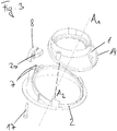
- the illustrated embodiment of a recessed spotlight 4 according to the invention for the ceiling installation has a three-part support for a lighting means, wherein in or on a first part 1 of the support a socket 5 (see. Fig. 2c ) is arranged for the lighting means and the first part 1 of the carrier about a first axis of rotation A 1 is rotatably arranged on a second part 2 of the carrier.
- the second part 2 of the carrier is arranged rotatably about a second axis of rotation A 2 on a third part 3 of the carrier.
- the second axis of rotation A 2 extends obliquely to the first axis of rotation A 1 .
- the second axis of rotation A 2 In mounting position in a horizontally extending ceiling, the second axis of rotation A 2 extends vertically and the first axis of rotation A 1 extends at an angle to the vertical.
- This slider 8 is movable into a first locking position, in which it rotates about a first locking means the first and second part 1, 2 relative to each other. Starting from the first locking position, the slider 8 is movable to a second locking position, in which it rotates about the first locking means the first and second part 1, 2 of the carrier still relative to each other and relative to a second locking means the third part 3 of the carrier relative to the first and second part 1, 2 of the carrier rotationally fixed.
- first scale 11 is particularly useful if the same angular position of the first relative to the second part 1, 2 of the carrier is to be set for a plurality of identical recessed spotlights 4.
- the first locking means may be formed as arranged on the slide 8 projection 9 and the locking device may have a ring gear 14, in which the projection 9 engages in the first locking position and so the first and the second part 1, 2 rotatably relative to each other.
- the second locking means may be formed as arranged on the slide 8 contact surface 10 which presses in the second locking position against the third part 3 and so the third part 3 relative to the first and second part 1, 2 rotationally fixed.
- a moving means 17 is provided for moving the slider 8 at least from the first to the second locking position.
- the moving means 17 is formed as a threaded pin or screw, and cooperates with a arranged in the slider 8 thread.
- the guide 7 is preferably arranged on the second part 2 of the carrier. In the exemplary embodiment shown, it has grooves which interact with webs 20 arranged on the slide 8.
- the slider 8 rests in a rest position on a surface provided with projections of the second part 2 and a rotation of the first part 1 of the carrier about the first axis of rotation A 1 a Noise generated.
- This is an audible signal to the operator, which facilitates his adjustment, especially when the view is obstructed on the recessed light 4.
- the projections are formed as a toothed rim 14.
- the ring gear 14 thus has a dual function, namely, on the one hand allows the engagement of the slider 8 in the first locking position and on the other hand, it acts together with a slide 8 arranged on the projection 9 as an acoustic signal generating device.
- Fig. 1 can be seen (from top to bottom): a heat sink 6 to dissipate the heat generated by the lamp, a reflector 13, by which light generated by the light source is deflected downward, the first part 1 of the carrier with sprocket 14, the second part 2 of Carrier with slide 8, the third part 3 of the carrier, one of the holder in the cover serving sleeve 15 which is provided with mounting springs 12 which engage behind the ceiling after insertion of the recessed spotlight 4 in an opening arranged in a ceiling and so the recessed spotlight 4th Can hold on the ceiling and a cover 16, which prevents the ingress of dust.
- Fig. 3 is the first axis of rotation A 1 recognizable, which forms an angle with the second axis of rotation A 2 .
- the actuating means 17 for the slider 8 is parallel to the second axis of rotation A 2 .
- a guide 7 for the slide 8 has two grooves, in which arranged on the slide 8 webs 20 engage.
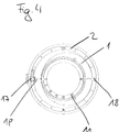
- Fig. 4 shows a disposed on the first part 1 of the carrier first scale 11.
- a arranged on the second part 2 of the carrier mark 19 shows the selected rotational position of the first part 1 of the carrier relative to the second part 2 of the carrier (here 0 °).
- On the second part 2 of the carrier a second scale 19 is arranged.
- the fastening means 17 shows the selected rotational position of the second part 2 of the carrier relative to the third part 3 of the carrier (here 0 °).
- Fig. 5 shows the slider 8. Visible is an opening 21 for the actuating means 17.
- the wall of the opening 21 may have a thread for the actuating means 17.
- a threaded nut is arranged (this can be poured in the manufacture of the slide 8 with or pressed after the manufacture of the slide 8 in the opening 21).
- the slider 8 has in its upper region a nose formed as a projection 9, which engages in the first locking position in the arranged on the first part 1 of the carrier ring gear 14 (see. Fig. 6b ) and thus produces a positive rotation between the first and second part 1, 2 of the carrier.
- the slider 8 has in its lower region a contact surface 10 which presses in the second locking position on the third part 3 of the carrier (see. Fig. 6c ) and thus produces a non-positive (frictional) rotation lock between the third and second part 3, 2 of the carrier.
- Fig. 6a to 6c show the stepwise locking of the individual parts 1, 2, 3 of the carrier to each other:
- the slide 8 is so far above that the projection 9 engages slightly in the ring gear 14. This position can be factory set.
- the slider 8 has along the guide 7 still game 8 for a slight further movement upwards.
- the teeth of the ring gear press the projection 9 and thus the slider 8 upwards, which is associated with a clearly audible acoustic signal ("click").
- a user turns the actuating means 17, z. B. with a screwdriver, the slider 8 moves along the guide 7 down and the projection 9 so far immersed in the sprocket 14, that he the sprocket fourteenth determines ( Fig. 6b ).
- the first locking position is reached.
- the contact surface 10 does not press on the third part 3 of the carrier and this can be rotated freely.
- a user turns the actuating means 17, z. B. with a screwdriver, the slider 8 moves further along the guide 7 down until the contact surface 10 rests on the third part 3 of the carrier and presses against it. The second locking position is reached.
Landscapes
- Engineering & Computer Science (AREA)
- General Engineering & Computer Science (AREA)
- Arrangement Of Elements, Cooling, Sealing, Or The Like Of Lighting Devices (AREA)
- Non-Portable Lighting Devices Or Systems Thereof (AREA)
Claims (11)
- Spot encastrable (4) destiné à être posé de manière encastrée ou en saillie au plafond, avec un support au moins en trois parties pour une lampe, dans lequel une douille (5) pour la lampe est disposée dans ou au niveau d'une première partie (1) du support et la première partie (1) du support est disposée au niveau d'une deuxième partie (2) du support de manière à pouvoir tourner autour d'un premier axe de rotation (A1), et la deuxième partie (2) du support est disposée au niveau d'une troisième partie (3) du support de manière à pouvoir tourner autour d'un deuxième axe de rotation (A2), dans lequel le deuxième axe de rotation (A2) s'étend de manière inclinée par rapport au premier axe de rotation (A1) et dans lequel un dispositif d'immobilisation servant à l'immobilisation en rotation au moins de la première et de la deuxième partie (1, 2) l'une par rapport à l'autre est prévu, dans lequel le dispositif d'immobilisation présente un coulisseau (8) guidé le long d'un guidage (7), qui peut être déplacé dans une première position d'immobilisation, dans laquelle le coulisseau (8) immobilise en rotation l'une par rapport à l'autre la première et la deuxième partie (1, 2) par l'intermédiaire d'un premier moyen d'immobilisation, caractérisé en ce que la troisième partie (3) du support peut être tournée encore par rapport à la première et à la deuxième partie (1, 2) du support dans la première position d'immobilisation, et dans lequel le coulisseau (8) peut être déplacé dans une deuxième position d'immobilisation, dans laquelle le coulisseau (8) immobilise en rotation la première et la deuxième partie (1, 2) l'une par rapport à l'autre par l'intermédiaire du premier moyen d'immobilisation et immobilise en rotation la troisième partie (3) par rapport à la première et à la deuxième partie (1, 2) par l'intermédiaire d'un deuxième moyen d'immobilisation.
- Spot encastrable selon la revendication précédente, dans lequel le premier moyen d'immobilisation est réalisé sous la forme d'une partie faisant saillie (9) disposée au niveau du coulisseau (8) et le dispositif d'immobilisation présente une couronne dentée (14), avec laquelle la partie faisant saillie (9) vient en prise dans la première position d'immobilisation et immobilise ainsi en rotation la première et la deuxième partie (1, 2) l'une par rapport à l'autre.
- Spot encastrable selon au moins l'une quelconque des revendications précédentes, dans lequel le deuxième moyen d'immobilisation est réalisé sous la forme d'une surface de compression (10) disposée au niveau du coulisseau (8), laquelle exerce une pression dans la deuxième position d'immobilisation contre la troisième partie (3) et immobilise ainsi en rotation la troisième partie (3) par rapport à la première et à la deuxième partie (1, 2).
- Spot encastrable selon au moins l'une quelconque des revendications précédentes, dans lequel est prévu un moyen de déplacement (17) servant à déplacer le coulisseau (8) au moins depuis la première dans la deuxième position d'immobilisation.
- Spot encastrable selon la revendication précédente, dans lequel le moyen de déplacement (17) est disposé au niveau de la troisième partie (3) du support.
- Spot encastrable selon au moins l'une quelconque des deux revendications précédentes, dans lequel le moyen de déplacement (17) est réalisé sous la forme d'une tige filetée ou d'une vis, et coopère avec un filetage disposé dans le coulisseau (8).
- Spot encastrable selon au moins l'une quelconque des revendications précédentes, dans lequel le guidage (7) est disposé au niveau de la deuxième partie (2) du support.
- Spot encastrable selon au moins l'une quelconque des revendications précédentes, dans lequel le coulisseau (8) repose dans une position de repos au niveau d'une surface, pourvue de parties faisant saillie, de la deuxième partie (2) et génère un bruit dans le cas d'une rotation de la première partie (1) du support autour du premier axe de rotation (A1), dans lequel de préférence les parties faisant saillie sont réalisées sous la forme d'une couronne dentée (14) selon la revendication 3.
- Spot encastrable selon au moins l'une quelconque des revendications précédentes, dans lequel une première graduation (11) pour le déplacement en rotation autour du premier axe de rotation (A1) est disposée au niveau du côté, tourné vers la lampe, de la première partie (1) du support.
- Spot encastrable selon au moins l'une quelconque des revendications précédentes, dans lequel une deuxième graduation (18) pour le déplacement en rotation autour du deuxième axe de rotation (A2) est disposée au niveau du côté, tourné vers la lampe, de la troisième partie (3) du support.
- Procédé de montage servant à monter un spot encastrable (4) selon au moins l'une quelconque des revendications précédentes dans ou au niveau d'un plafond, dans lequel une position en rotation souhaitée de la première partie (1) du support par rapport à la deuxième partie (2) du support est réglée avant le montage du spot encastrable (4) dans ou au niveau du plafond et immédiatement après le coulisseau (8) est déplacé dans la première position d'immobilisation et dans lequel une position en rotation souhaitée de la troisième partie (3) du support est immédiatement après réglée par rapport à la deuxième partie (2) du support avant ou après le montage du spot encastrable (4) dans ou au niveau du plafond, et le coulisseau (8) est déplacé immédiatement après dans la deuxième position d'immobilisation.
Priority Applications (1)
| Application Number | Priority Date | Filing Date | Title |
|---|---|---|---|
| EP16159993.1A EP3217071B1 (fr) | 2016-03-11 | 2016-03-11 | Projecteur pour pose encastree ou en saillie au plafond |
Applications Claiming Priority (1)
| Application Number | Priority Date | Filing Date | Title |
|---|---|---|---|
| EP16159993.1A EP3217071B1 (fr) | 2016-03-11 | 2016-03-11 | Projecteur pour pose encastree ou en saillie au plafond |
Publications (2)
| Publication Number | Publication Date |
|---|---|
| EP3217071A1 EP3217071A1 (fr) | 2017-09-13 |
| EP3217071B1 true EP3217071B1 (fr) | 2018-06-27 |
Family
ID=55646286
Family Applications (1)
| Application Number | Title | Priority Date | Filing Date |
|---|---|---|---|
| EP16159993.1A Not-in-force EP3217071B1 (fr) | 2016-03-11 | 2016-03-11 | Projecteur pour pose encastree ou en saillie au plafond |
Country Status (1)
| Country | Link |
|---|---|
| EP (1) | EP3217071B1 (fr) |
Cited By (1)
| Publication number | Priority date | Publication date | Assignee | Title |
|---|---|---|---|---|
| EP4481266A1 (fr) * | 2023-06-19 | 2024-12-25 | RIDI Leuchten GmbH | Luminaire encastré |
Families Citing this family (2)
| Publication number | Priority date | Publication date | Assignee | Title |
|---|---|---|---|---|
| CN107726132B (zh) * | 2017-10-09 | 2024-04-02 | 广东艾罗照明科技股份有限公司 | 一种射灯 |
| DE102018001652B4 (de) * | 2018-03-02 | 2019-10-02 | H4X E.U. | Leuchte |
Family Cites Families (4)
| Publication number | Priority date | Publication date | Assignee | Title |
|---|---|---|---|---|
| US2716185A (en) | 1950-04-25 | 1955-08-23 | Rambusch Decorating Company | Recessed lighting equipment |
| US7434967B2 (en) * | 2005-02-25 | 2008-10-14 | Genlyte Thomas Group, Llc | Worm gear drive aiming and locking mechanism |
| EP2314909B1 (fr) * | 2009-10-22 | 2012-04-18 | Antares Iluminación, S.A. | Dispositif d'éclairage |
| US8960976B2 (en) * | 2012-12-04 | 2015-02-24 | Vision Motor Sports, Inc. | Mounting apparatus for adjustably positioning a lighting device |
-
2016
- 2016-03-11 EP EP16159993.1A patent/EP3217071B1/fr not_active Not-in-force
Non-Patent Citations (1)
| Title |
|---|
| None * |
Cited By (1)
| Publication number | Priority date | Publication date | Assignee | Title |
|---|---|---|---|---|
| EP4481266A1 (fr) * | 2023-06-19 | 2024-12-25 | RIDI Leuchten GmbH | Luminaire encastré |
Also Published As
| Publication number | Publication date |
|---|---|
| EP3217071A1 (fr) | 2017-09-13 |
Similar Documents
| Publication | Publication Date | Title |
|---|---|---|
| EP2539629B1 (fr) | Lampe intégrée comportant un corps de base et un réflecteur en forme de dôme | |
| DE102012221412B4 (de) | Einbauleuchte | |
| EP2093478A1 (fr) | Lampe intégrée | |
| EP3217071B1 (fr) | Projecteur pour pose encastree ou en saillie au plafond | |
| EP2796780B1 (fr) | Luminaire doté d'une caractéristique de rayonnement lumineux réglable | |
| EP3209933B1 (fr) | Plafonnier à spots lumineux | |
| EP2929234B1 (fr) | Luminaire encastre dans un plan | |
| EP2363634B1 (fr) | Lampe à DEL encastrée, notamment plafonnière | |
| DE102014205663B4 (de) | Halteanordnung für ein Funktionsbauteil einer Beleuchtungsvorrichtung, sowie Beleuchtungsvorrichtung | |
| DE202012104544U1 (de) | Deckeneinbauleuchte | |
| DE4121576C2 (de) | Leuchte mit verstellbarer Lampe | |
| DE3244516C2 (de) | Vorrichtung zur lösbaren Verbindung des Geräteträgers mit der Schiene einer Leuchte für Leuchtstofflampen | |
| EP4174889B1 (fr) | Appareil d'installation électrique éclairé, tel que commutateur ou palpeur | |
| EP3209934B1 (fr) | Plafonnier à spots lumineux | |
| DE102014200998B4 (de) | Verstelleinrichtung für einen Strahler einer Leuchte sowie Leuchte mit selbiger | |
| EP2602542B1 (fr) | Dispositif d'éclairage | |
| EP3446031B1 (fr) | Appareil d'éclairage d'armoire de distribution pourvu d'une platine à source lumineuse réglable | |
| DE19757698A1 (de) | Vorrichtung zum Einbau von Schaltern in eine Bedienblende eines Haushaltsgeräts | |
| EP2184746A2 (fr) | Appareil de réglage électromécanique doté d'un axe rotatif | |
| EP2138763A2 (fr) | Projecteur et systéme rail conducteur pour un tel projecteur | |
| EP3396234B1 (fr) | Dispositif d'éclairage | |
| EP2711622B1 (fr) | Lampe dotée d'une protection contre le contact | |
| EP2146140B1 (fr) | Dispositif d'éclairage réglable | |
| DE102013009848B4 (de) | Vorrichtung zur Lagesicherung und Befestigung einer kreisförmigen Abdeck- oder Streuscheibe in einem kreisringförmigen Halteteil, insbesondere für Leuchtenkörper | |
| DE9116516U1 (de) | Leuchte, insbesondere Möbelleuchte |
Legal Events
| Date | Code | Title | Description |
|---|---|---|---|
| PUAI | Public reference made under article 153(3) epc to a published international application that has entered the european phase |
Free format text: ORIGINAL CODE: 0009012 |
|
| STAA | Information on the status of an ep patent application or granted ep patent |
Free format text: STATUS: REQUEST FOR EXAMINATION WAS MADE |
|
| 17P | Request for examination filed |
Effective date: 20170329 |
|
| AK | Designated contracting states |
Kind code of ref document: A1 Designated state(s): AL AT BE BG CH CY CZ DE DK EE ES FI FR GB GR HR HU IE IS IT LI LT LU LV MC MK MT NL NO PL PT RO RS SE SI SK SM TR |
|
| AX | Request for extension of the european patent |
Extension state: BA ME |
|
| RIC1 | Information provided on ipc code assigned before grant |
Ipc: F21V 21/30 20060101ALI20170929BHEP Ipc: F21S 8/02 20060101AFI20170929BHEP |
|
| GRAP | Despatch of communication of intention to grant a patent |
Free format text: ORIGINAL CODE: EPIDOSNIGR1 |
|
| STAA | Information on the status of an ep patent application or granted ep patent |
Free format text: STATUS: GRANT OF PATENT IS INTENDED |
|
| INTG | Intention to grant announced |
Effective date: 20171115 |
|
| GRAS | Grant fee paid |
Free format text: ORIGINAL CODE: EPIDOSNIGR3 |
|
| GRAA | (expected) grant |
Free format text: ORIGINAL CODE: 0009210 |
|
| STAA | Information on the status of an ep patent application or granted ep patent |
Free format text: STATUS: THE PATENT HAS BEEN GRANTED |
|
| AK | Designated contracting states |
Kind code of ref document: B1 Designated state(s): AL AT BE BG CH CY CZ DE DK EE ES FI FR GB GR HR HU IE IS IT LI LT LU LV MC MK MT NL NO PL PT RO RS SE SI SK SM TR |
|
| REG | Reference to a national code |
Ref country code: GB Ref legal event code: FG4D Free format text: NOT ENGLISH |
|
| REG | Reference to a national code |
Ref country code: AT Ref legal event code: REF Ref document number: 1012655 Country of ref document: AT Kind code of ref document: T Effective date: 20180715 |
|
| REG | Reference to a national code |
Ref country code: IE Ref legal event code: FG4D Free format text: LANGUAGE OF EP DOCUMENT: GERMAN |
|
| REG | Reference to a national code |
Ref country code: DE Ref legal event code: R096 Ref document number: 502016001320 Country of ref document: DE |
|
| REG | Reference to a national code |
Ref country code: CH Ref legal event code: NV Representative=s name: ISLER AND PEDRAZZINI AG, CH |
|
| PG25 | Lapsed in a contracting state [announced via postgrant information from national office to epo] |
Ref country code: FI Free format text: LAPSE BECAUSE OF FAILURE TO SUBMIT A TRANSLATION OF THE DESCRIPTION OR TO PAY THE FEE WITHIN THE PRESCRIBED TIME-LIMIT Effective date: 20180627 Ref country code: BG Free format text: LAPSE BECAUSE OF FAILURE TO SUBMIT A TRANSLATION OF THE DESCRIPTION OR TO PAY THE FEE WITHIN THE PRESCRIBED TIME-LIMIT Effective date: 20180927 Ref country code: NO Free format text: LAPSE BECAUSE OF FAILURE TO SUBMIT A TRANSLATION OF THE DESCRIPTION OR TO PAY THE FEE WITHIN THE PRESCRIBED TIME-LIMIT Effective date: 20180927 Ref country code: SE Free format text: LAPSE BECAUSE OF FAILURE TO SUBMIT A TRANSLATION OF THE DESCRIPTION OR TO PAY THE FEE WITHIN THE PRESCRIBED TIME-LIMIT Effective date: 20180627 Ref country code: LT Free format text: LAPSE BECAUSE OF FAILURE TO SUBMIT A TRANSLATION OF THE DESCRIPTION OR TO PAY THE FEE WITHIN THE PRESCRIBED TIME-LIMIT Effective date: 20180627 |
|
| REG | Reference to a national code |
Ref country code: NL Ref legal event code: MP Effective date: 20180627 |
|
| REG | Reference to a national code |
Ref country code: LT Ref legal event code: MG4D |
|
| PG25 | Lapsed in a contracting state [announced via postgrant information from national office to epo] |
Ref country code: LV Free format text: LAPSE BECAUSE OF FAILURE TO SUBMIT A TRANSLATION OF THE DESCRIPTION OR TO PAY THE FEE WITHIN THE PRESCRIBED TIME-LIMIT Effective date: 20180627 Ref country code: RS Free format text: LAPSE BECAUSE OF FAILURE TO SUBMIT A TRANSLATION OF THE DESCRIPTION OR TO PAY THE FEE WITHIN THE PRESCRIBED TIME-LIMIT Effective date: 20180627 Ref country code: HR Free format text: LAPSE BECAUSE OF FAILURE TO SUBMIT A TRANSLATION OF THE DESCRIPTION OR TO PAY THE FEE WITHIN THE PRESCRIBED TIME-LIMIT Effective date: 20180627 Ref country code: GR Free format text: LAPSE BECAUSE OF FAILURE TO SUBMIT A TRANSLATION OF THE DESCRIPTION OR TO PAY THE FEE WITHIN THE PRESCRIBED TIME-LIMIT Effective date: 20180928 |
|
| PG25 | Lapsed in a contracting state [announced via postgrant information from national office to epo] |
Ref country code: NL Free format text: LAPSE BECAUSE OF FAILURE TO SUBMIT A TRANSLATION OF THE DESCRIPTION OR TO PAY THE FEE WITHIN THE PRESCRIBED TIME-LIMIT Effective date: 20180627 |
|
| PG25 | Lapsed in a contracting state [announced via postgrant information from national office to epo] |
Ref country code: RO Free format text: LAPSE BECAUSE OF FAILURE TO SUBMIT A TRANSLATION OF THE DESCRIPTION OR TO PAY THE FEE WITHIN THE PRESCRIBED TIME-LIMIT Effective date: 20180627 Ref country code: IS Free format text: LAPSE BECAUSE OF FAILURE TO SUBMIT A TRANSLATION OF THE DESCRIPTION OR TO PAY THE FEE WITHIN THE PRESCRIBED TIME-LIMIT Effective date: 20181027 Ref country code: EE Free format text: LAPSE BECAUSE OF FAILURE TO SUBMIT A TRANSLATION OF THE DESCRIPTION OR TO PAY THE FEE WITHIN THE PRESCRIBED TIME-LIMIT Effective date: 20180627 Ref country code: CZ Free format text: LAPSE BECAUSE OF FAILURE TO SUBMIT A TRANSLATION OF THE DESCRIPTION OR TO PAY THE FEE WITHIN THE PRESCRIBED TIME-LIMIT Effective date: 20180627 Ref country code: SK Free format text: LAPSE BECAUSE OF FAILURE TO SUBMIT A TRANSLATION OF THE DESCRIPTION OR TO PAY THE FEE WITHIN THE PRESCRIBED TIME-LIMIT Effective date: 20180627 Ref country code: PL Free format text: LAPSE BECAUSE OF FAILURE TO SUBMIT A TRANSLATION OF THE DESCRIPTION OR TO PAY THE FEE WITHIN THE PRESCRIBED TIME-LIMIT Effective date: 20180627 |
|
| PG25 | Lapsed in a contracting state [announced via postgrant information from national office to epo] |
Ref country code: SM Free format text: LAPSE BECAUSE OF FAILURE TO SUBMIT A TRANSLATION OF THE DESCRIPTION OR TO PAY THE FEE WITHIN THE PRESCRIBED TIME-LIMIT Effective date: 20180627 Ref country code: IT Free format text: LAPSE BECAUSE OF FAILURE TO SUBMIT A TRANSLATION OF THE DESCRIPTION OR TO PAY THE FEE WITHIN THE PRESCRIBED TIME-LIMIT Effective date: 20180627 Ref country code: ES Free format text: LAPSE BECAUSE OF FAILURE TO SUBMIT A TRANSLATION OF THE DESCRIPTION OR TO PAY THE FEE WITHIN THE PRESCRIBED TIME-LIMIT Effective date: 20180627 |
|
| REG | Reference to a national code |
Ref country code: DE Ref legal event code: R097 Ref document number: 502016001320 Country of ref document: DE |
|
| PLBE | No opposition filed within time limit |
Free format text: ORIGINAL CODE: 0009261 |
|
| STAA | Information on the status of an ep patent application or granted ep patent |
Free format text: STATUS: NO OPPOSITION FILED WITHIN TIME LIMIT |
|
| PG25 | Lapsed in a contracting state [announced via postgrant information from national office to epo] |
Ref country code: DK Free format text: LAPSE BECAUSE OF FAILURE TO SUBMIT A TRANSLATION OF THE DESCRIPTION OR TO PAY THE FEE WITHIN THE PRESCRIBED TIME-LIMIT Effective date: 20180627 |
|
| 26N | No opposition filed |
Effective date: 20190328 |
|
| PG25 | Lapsed in a contracting state [announced via postgrant information from national office to epo] |
Ref country code: SI Free format text: LAPSE BECAUSE OF FAILURE TO SUBMIT A TRANSLATION OF THE DESCRIPTION OR TO PAY THE FEE WITHIN THE PRESCRIBED TIME-LIMIT Effective date: 20180627 |
|
| PG25 | Lapsed in a contracting state [announced via postgrant information from national office to epo] |
Ref country code: MC Free format text: LAPSE BECAUSE OF FAILURE TO SUBMIT A TRANSLATION OF THE DESCRIPTION OR TO PAY THE FEE WITHIN THE PRESCRIBED TIME-LIMIT Effective date: 20180627 |
|
| PG25 | Lapsed in a contracting state [announced via postgrant information from national office to epo] |
Ref country code: AL Free format text: LAPSE BECAUSE OF FAILURE TO SUBMIT A TRANSLATION OF THE DESCRIPTION OR TO PAY THE FEE WITHIN THE PRESCRIBED TIME-LIMIT Effective date: 20180627 Ref country code: LU Free format text: LAPSE BECAUSE OF NON-PAYMENT OF DUE FEES Effective date: 20190311 |
|
| REG | Reference to a national code |
Ref country code: BE Ref legal event code: MM Effective date: 20190331 |
|
| PG25 | Lapsed in a contracting state [announced via postgrant information from national office to epo] |
Ref country code: IE Free format text: LAPSE BECAUSE OF NON-PAYMENT OF DUE FEES Effective date: 20190311 |
|
| PG25 | Lapsed in a contracting state [announced via postgrant information from national office to epo] |
Ref country code: BE Free format text: LAPSE BECAUSE OF NON-PAYMENT OF DUE FEES Effective date: 20190331 |
|
| PG25 | Lapsed in a contracting state [announced via postgrant information from national office to epo] |
Ref country code: TR Free format text: LAPSE BECAUSE OF FAILURE TO SUBMIT A TRANSLATION OF THE DESCRIPTION OR TO PAY THE FEE WITHIN THE PRESCRIBED TIME-LIMIT Effective date: 20180627 |
|
| PG25 | Lapsed in a contracting state [announced via postgrant information from national office to epo] |
Ref country code: MT Free format text: LAPSE BECAUSE OF FAILURE TO SUBMIT A TRANSLATION OF THE DESCRIPTION OR TO PAY THE FEE WITHIN THE PRESCRIBED TIME-LIMIT Effective date: 20180627 Ref country code: PT Free format text: LAPSE BECAUSE OF FAILURE TO SUBMIT A TRANSLATION OF THE DESCRIPTION OR TO PAY THE FEE WITHIN THE PRESCRIBED TIME-LIMIT Effective date: 20181029 |
|
| PG25 | Lapsed in a contracting state [announced via postgrant information from national office to epo] |
Ref country code: CY Free format text: LAPSE BECAUSE OF FAILURE TO SUBMIT A TRANSLATION OF THE DESCRIPTION OR TO PAY THE FEE WITHIN THE PRESCRIBED TIME-LIMIT Effective date: 20180627 |
|
| PG25 | Lapsed in a contracting state [announced via postgrant information from national office to epo] |
Ref country code: HU Free format text: LAPSE BECAUSE OF FAILURE TO SUBMIT A TRANSLATION OF THE DESCRIPTION OR TO PAY THE FEE WITHIN THE PRESCRIBED TIME-LIMIT; INVALID AB INITIO Effective date: 20160311 |
|
| PGFP | Annual fee paid to national office [announced via postgrant information from national office to epo] |
Ref country code: GB Payment date: 20220314 Year of fee payment: 7 Ref country code: CH Payment date: 20220321 Year of fee payment: 7 Ref country code: AT Payment date: 20220323 Year of fee payment: 7 |
|
| PGFP | Annual fee paid to national office [announced via postgrant information from national office to epo] |
Ref country code: FR Payment date: 20220331 Year of fee payment: 7 |
|
| PG25 | Lapsed in a contracting state [announced via postgrant information from national office to epo] |
Ref country code: MK Free format text: LAPSE BECAUSE OF FAILURE TO SUBMIT A TRANSLATION OF THE DESCRIPTION OR TO PAY THE FEE WITHIN THE PRESCRIBED TIME-LIMIT Effective date: 20180627 |
|
| PGFP | Annual fee paid to national office [announced via postgrant information from national office to epo] |
Ref country code: DE Payment date: 20220406 Year of fee payment: 7 |
|
| REG | Reference to a national code |
Ref country code: DE Ref legal event code: R119 Ref document number: 502016001320 Country of ref document: DE |
|
| REG | Reference to a national code |
Ref country code: CH Ref legal event code: PL |
|
| REG | Reference to a national code |
Ref country code: AT Ref legal event code: MM01 Ref document number: 1012655 Country of ref document: AT Kind code of ref document: T Effective date: 20230311 |
|
| GBPC | Gb: european patent ceased through non-payment of renewal fee |
Effective date: 20230311 |
|
| PG25 | Lapsed in a contracting state [announced via postgrant information from national office to epo] |
Ref country code: GB Free format text: LAPSE BECAUSE OF NON-PAYMENT OF DUE FEES Effective date: 20230311 |
|
| PG25 | Lapsed in a contracting state [announced via postgrant information from national office to epo] |
Ref country code: LI Free format text: LAPSE BECAUSE OF NON-PAYMENT OF DUE FEES Effective date: 20230331 Ref country code: GB Free format text: LAPSE BECAUSE OF NON-PAYMENT OF DUE FEES Effective date: 20230311 Ref country code: FR Free format text: LAPSE BECAUSE OF NON-PAYMENT OF DUE FEES Effective date: 20230331 Ref country code: DE Free format text: LAPSE BECAUSE OF NON-PAYMENT OF DUE FEES Effective date: 20231003 Ref country code: CH Free format text: LAPSE BECAUSE OF NON-PAYMENT OF DUE FEES Effective date: 20230331 Ref country code: AT Free format text: LAPSE BECAUSE OF NON-PAYMENT OF DUE FEES Effective date: 20230311 |