EP3217090B1 - Improved adapter for supporting and electrically connecting a lighting apparatus to an electrified track and lighting unit using the same - Google Patents
Improved adapter for supporting and electrically connecting a lighting apparatus to an electrified track and lighting unit using the same Download PDFInfo
- Publication number
- EP3217090B1 EP3217090B1 EP17159913.7A EP17159913A EP3217090B1 EP 3217090 B1 EP3217090 B1 EP 3217090B1 EP 17159913 A EP17159913 A EP 17159913A EP 3217090 B1 EP3217090 B1 EP 3217090B1
- Authority
- EP
- European Patent Office
- Prior art keywords
- box
- adapter
- lighting apparatus
- configuration
- extraction
- Prior art date
- Legal status (The legal status is an assumption and is not a legal conclusion. Google has not performed a legal analysis and makes no representation as to the accuracy of the status listed.)
- Active
Links
Images


Classifications
-
- F—MECHANICAL ENGINEERING; LIGHTING; HEATING; WEAPONS; BLASTING
- F21—LIGHTING
- F21V—FUNCTIONAL FEATURES OR DETAILS OF LIGHTING DEVICES OR SYSTEMS THEREOF; STRUCTURAL COMBINATIONS OF LIGHTING DEVICES WITH OTHER ARTICLES, NOT OTHERWISE PROVIDED FOR
- F21V21/00—Supporting, suspending, or attaching arrangements for lighting devices; Hand grips
- F21V21/34—Supporting elements displaceable along a guiding element
- F21V21/35—Supporting elements displaceable along a guiding element with direct electrical contact between the supporting element and electric conductors running along the guiding element
-
- F—MECHANICAL ENGINEERING; LIGHTING; HEATING; WEAPONS; BLASTING
- F21—LIGHTING
- F21S—NON-PORTABLE LIGHTING DEVICES; SYSTEMS THEREOF; VEHICLE LIGHTING DEVICES SPECIALLY ADAPTED FOR VEHICLE EXTERIORS
- F21S8/00—Lighting devices intended for fixed installation
- F21S8/03—Lighting devices intended for fixed installation of surface-mounted type
- F21S8/038—Lighting devices intended for fixed installation of surface-mounted type intended to be mounted on a light track
-
- H—ELECTRICITY
- H01—ELECTRIC ELEMENTS
- H01R—ELECTRICALLY-CONDUCTIVE CONNECTIONS; STRUCTURAL ASSOCIATIONS OF A PLURALITY OF MUTUALLY-INSULATED ELECTRICAL CONNECTING ELEMENTS; COUPLING DEVICES; CURRENT COLLECTORS
- H01R25/00—Coupling parts adapted for simultaneous co-operation with two or more identical counterparts, e.g. for distributing energy to two or more circuits
- H01R25/14—Rails or bus-bars constructed so that the counterparts can be connected thereto at any point along their length
- H01R25/142—Their counterparts
-
- F—MECHANICAL ENGINEERING; LIGHTING; HEATING; WEAPONS; BLASTING
- F21—LIGHTING
- F21V—FUNCTIONAL FEATURES OR DETAILS OF LIGHTING DEVICES OR SYSTEMS THEREOF; STRUCTURAL COMBINATIONS OF LIGHTING DEVICES WITH OTHER ARTICLES, NOT OTHERWISE PROVIDED FOR
- F21V23/00—Arrangement of electric circuit elements in or on lighting devices
- F21V23/06—Arrangement of electric circuit elements in or on lighting devices the elements being coupling devices, e.g. connectors
-
- F—MECHANICAL ENGINEERING; LIGHTING; HEATING; WEAPONS; BLASTING
- F21—LIGHTING
- F21Y—INDEXING SCHEME ASSOCIATED WITH SUBCLASSES F21K, F21L, F21S and F21V, RELATING TO THE FORM OR THE KIND OF THE LIGHT SOURCES OR OF THE COLOUR OF THE LIGHT EMITTED
- F21Y2101/00—Point-like light sources
-
- F—MECHANICAL ENGINEERING; LIGHTING; HEATING; WEAPONS; BLASTING
- F21—LIGHTING
- F21Y—INDEXING SCHEME ASSOCIATED WITH SUBCLASSES F21K, F21L, F21S and F21V, RELATING TO THE FORM OR THE KIND OF THE LIGHT SOURCES OR OF THE COLOUR OF THE LIGHT EMITTED
- F21Y2103/00—Elongate light sources, e.g. fluorescent tubes
- F21Y2103/10—Elongate light sources, e.g. fluorescent tubes comprising a linear array of point-like light-generating elements
-
- F—MECHANICAL ENGINEERING; LIGHTING; HEATING; WEAPONS; BLASTING
- F21—LIGHTING
- F21Y—INDEXING SCHEME ASSOCIATED WITH SUBCLASSES F21K, F21L, F21S and F21V, RELATING TO THE FORM OR THE KIND OF THE LIGHT SOURCES OR OF THE COLOUR OF THE LIGHT EMITTED
- F21Y2115/00—Light-generating elements of semiconductor light sources
- F21Y2115/10—Light-emitting diodes [LED]
Definitions
- the present invention relates to an improved adapter for supporting and electrically connecting a lighting apparatus to an electrified track, particularly suitable for the support and the electrical connection of elongated lighting apparatus or linear lighting apparatus.
- the present invention also relates to a lighting unit employing said adapter.
- the electrified track system for supporting and connecting lighting apparatus is designed for lighting specific points or limited areas, respectively, for example by means of spotlights or downlights.
- this system offers a high degree of flexibility in relation to the number and position of the lighting apparatus that can be connected, allowing them to be easily moved, added or removed.
- Components are known for attaching and electrically connecting the spotlights to the electrified track, which have the dual function of ensuring the electrical and mechanical connection between the electrified track and the spotlight, also known as electromechanical support and connection adapters.
- Known adapters are provided with a system for attaching to the track usually involving a double insert operation into the track and subsequent locking by turning levers that at the same time cause the extraction of both suspension flaps and of the electrical contacts.
- An example of one such adapter, according to the preamble of claim 1, is disclosed in document DE 3812586 A1 .
- adapters of known type are not able to offer such a result.
- the space that is necessary in order for the installer to be able to mount the known adapters in the track such as the space that allows the lever to turn, and the encumbrance of the adapters themselves, are two factors which, on the one hand, affect the continuity of light, creating shaded areas between one apparatus and the other due to the presence of the adapter and the space required for the fixing operations and on the other hand, they do not offer an optimal result in terms of size reduction and miniaturization of the solutions, in that once installed the devices do not adhere perfectly to the track.
- the Applicant has therefore felt the need to make an adapter for supporting and electrically connecting a lighting apparatus to an electrified track especially designed for the installation of linear lighting apparatus, thus not being subject to the above drawbacks.
- the problem underlying the present invention is to devise an adapter for supporting and electrically connecting a lighting apparatus to an electrified track that allows imparting to a set of linear lighting apparatus installed on the track the effect of a single body without discontinuity or, in other words, light without interruption or shaded areas.
- one object of the present invention is to make an adapter for supporting and electrically connecting a lighting apparatus to an electrified track that allows installing linear lighting apparatus in perfect adherence to both the electrified track and to any adjacent lighting apparatus, in case of continuous row installation.
- one object of the present invention is to devise an adapter for supporting and electrically connecting a lighting apparatus to an electrified track that simplifies installation by obtaining the insertion into the track as well as the extraction of the suspension flaps and electrical contacts substantially with a single action.
- the invention therefore relates to an adapter for supporting and electrically connecting a lighting apparatus to an electrified track, comprising a box-like body at whose interior a mechanism is housed for extracting and retracting at least one electrical contact such that the box-like body is able to assume a first compact configuration, wherein the at least one electrical contact is substantially housed inside the box-like body, and a second configuration wherein the at least one electrical contact is at least partially extracted from the box-like body, the box-like body being associated with at least one interface element for coupling to a lightning apparatus and is characterized in that the interface element is movable between a first extracted configuration and a second retracted configuration with respect to the box-like body, wherein the retraction and extraction movements respectively determine the passage of the box-like body from its first compact configuration to its second extracted configuration and vice versa.
- the Applicant has found that due to the particular conformation of the interface element to the lighting apparatus and its interaction with the insertion and retraction mechanism of at least one electrical contact, it is possible to mount the adapter into the electrified track and electrically connect it substantially with a single action. Installation operations therefore become quicker and easier.
- This feature also allows, on the one hand, making the electrified tracks without providing appropriate spaces for moving the controls for the extraction of the electrical contacts and/or any suspension flaps. On the other hand, it allows housing substantially the entire adapter within the electrified track. This makes it possible to install the lighting apparatus substantially without shaded areas or interruptions, in the case of installation of a plurality of lighting apparatus in a row, thus obtaining the effect of a single body without discontinuity.
- the invention relates to a lighting unit comprising a lighting apparatus preferably of the linear type, provided with a support element and with at least one light source constrained to the same, and an adapter for supporting and electrically connecting the lighting apparatus to an electrified track and is characterized in that the adapter is of the type described above.
- the lighting unit according to the invention achieves the technical effects described above in relation to the adapter for supporting and electrically connecting a lighting apparatus to an electrified track.
- the present invention may have at least one of the following preferred features; the latter may in particular be combined with each other as desired to meet specific application requirements.
- the at least one interface element comprises a cam that cooperates with the extraction and retraction mechanism and determines the actuation thereof.
- the extraction and retraction mechanism comprises a support element that carries the electrical contacts on a first side and a projection on a second side transverse to the first.
- the projection is engaged in the cam such that a first translational movement in retraction and extraction of the at least one interface element with respect to the box-like body determines a second translational movement of the support element along a direction transverse to the first movement.
- this allows obtaining both the insertion of the adapter inside the track and the electrical connection to the same with a single action. It is in fact sufficient for the installer to push the adapter inside the track up to reach the condition in which the interface element is also fully inserted. In such a configuration, in fact, it has already been obtained that the electrical contacts are in their extracted configuration of connection to the conductors of the track.
- the support element carries at least one support flap on the first side, the at least one support flap being able to assume a first configuration of full housing inside the box-like body and a second configuration of at least partial extraction from the box-like body, the passage between the first and the second configuration of the support flap being carried out through the movements of the at least one interface element in retraction and extraction from the box-like body.
- the extraction of the support flaps is also carried out by the same insertion action.
- a firm constraint of the adapter, and therefore also of the light apparatus, to the electrified track is thus ensured.
- the at least one electrical contact and the at least one support flap are extractable from the box-like body through corresponding openings formed on the surface of the same.
- the at least one interface element comprises means for blocking the translation with respect to the box-like body.
- the blocking means comprise a hook which, in non-use condition of the adapter, is adapted to engage in a blocking opening formed on the outer surface of the box-like body.
- the hook is maintained in its engagement position with the blocking opening by elastic means.
- This advantageous device allows, before use, keeping the adapter in an extracted configuration.
- the blocking opening is formed on the surface of the box-like body in such a position whereby, once the box-like body is substantially inserted in the electrified track, the hook is brought into a condition of disengagement with respect to such a blocking opening in contrast to the action of the elastic means.
- this device allows one to automatically deactivate the blocking means once the adapter is in condition of substantial insertion into the track.
- the installation operation can therefore take place substantially in continuity without the need of special operations for releasing the interface elements.
- the at least an interface element has an upturned T plan shape.
- the at least one interface element comprises a first portion shaped as a stem insertable into the box-like body and a second portion having at least one end part adapted to engage with a connection interface of the lighting apparatus.
- the box-like body comprises, on an outer surface thereof, a plurality of engagement flaps with an inner wall of the electrified track.
- the engagement flaps interfere with the inner wall of the electrified track, resulting in a condition of first engagement between the two elements.
- the engagement flaps have a chamfered conformation.
- the conformation of the engagement flaps is such as to facilitate the removal of the adapter from the track, despite the condition of engagement with the inner wall of the same.
- the box-like body has an elongated shape along an axis of development and is associated with two interface elements for fastening the lighting apparatus arranged mutually spaced apart with respect to the axis of development.
- the support element of the lighting apparatus comprises at least one interface recess for the connection to at least one end part of the at least one interface element, the at least one recess and the at least one end part having complementary conformation so as to mutually engage and therefore assume a support configuration of the lighting apparatus by the at least one interface element.
- the support element comprises at least one supplementary support accessory suitable for engagement in the electrified track.
- the supplementary support accessory is associated to the adapter, thus contributing to the support of the lighting apparatus on track 60.
- a lighting unit 10, 50 comprising a lighting apparatus 50 and an adapter 10 for supporting and electrically connecting such a lighting apparatus 50 to an electrified track 60.
- the lighting apparatus 50 comprises a profiled element 52 which acts as a support of a LED light source 53.
- the profiled element 52 of the lighting apparatus 50 further implements a pair of interface recesses 51 for connecting to adapter 10.
- the electrified track 60 shown comprises a profiled element 62 provided with a plurality of sub-profiles 61 projecting inwards, made of an insulating material for defining single housings for a plurality of electrical conductors 63.
- Adapter 10 for support and electrical connection comprises a box-like body 11 having an elongated conformation along an axis of development, which houses the electronics 30 required for the power supply of the lighting apparatus 50 and an extraction and retraction mechanism 20 of a plurality of electrical contacts 21, 22, 23, for connecting electronics 30 to the electrical conductors 63 of the electrified track 60.
- the ground contact 26 projects above the box-like body 11, which when the adapter is inserted into track 60, contacts the profiled element 62 of the same 60.
- the box-like body 11 can assume a first compact configuration, in which the electrical contacts 21, 22, 23 are substantially housed within the box-like body 11 (see figures 3a-3c ), and a second configuration in which the electrical contacts 21, 22, 23 are at least partially extracted from the box-like body 11 (see figures 3d and 3e ).
- the box-like body 1 is associated with two interface elements 12, 13 for fastening the lighting apparatus 50 arranged mutually spaced apart with respect to the axis of development A.
- the interface elements 12, 13 have an inverted T plan shape, comprising a first portion 12a, 13a shaped as a stem insertable into the box-like body 11 and a second portion 12b, 13b placed transverse to the stem portion 12a, 13a.
- the second portion 12b, 13b has a pair of end parts 12b', 13b' with a conformation complementary to the respective connection interfaces 51 provided on the profiled element 52 of the lighting apparatus 50 so as to come into mutual engagement and therefore assume a support configuration of the lighting apparatus 50 by the interface elements 12, 13.
- the interface elements 12, 13 are movable between a first extracted configuration and a second retracted configuration with respect to the box-like body 11.
- the retraction and extraction movements respectively cause the switching of the box-like body 11 from its first compact configuration to its second configuration with contacts 21, 22, 23 extracted, and vice versa.
- the first portion 12a, 13a of at least one of the two interface elements 12, 13 comprises a cam 14 that cooperates with the extraction and retraction mechanism 20 and determines the actuation thereof.
- the extraction and retraction mechanism 20 comprises a support element 24 that carries the electrical contacts 21, 22, 23 in addition to a support flap 27 on a first side, and a projection 25 on a second side transverse to the first, which engages with cam 14.
- cam 14 and projection 25 is such that a translation of the interface element 12, 13 inwards of the box-like body 11 determines a translation of the support element 24 in the transverse direction, making the electrical contacts 21, 22, 23 and the support flap 27 come out of the box-like body 11 through corresponding openings 15, 15' made on surface 11a of the same 11.
- the box-like body 11 comprises, on its outer surface 11a, a plurality of engagement flaps 16a, 16b, which with adapter 10 at least partially inserted into the electrified track 60, interfere with the plurality of sub-profiles 61 inside said track 60, resulting in a condition of first engagement between the two elements (engagement flaps 16a, 16b and sub-profiles 61).
- engagement flaps 16a, 16b have a chamfered conformation to facilitate the removal of adapter 10 from track 60, despite the condition of engagement with sub-profiles 61 within track 60.
- the interface elements 12, 13 comprise blocking means 17 of the translation with respect to the box-like body 11 provided with a hook 17a which, in non-use condition of adapter 10, engages in a blocking opening 18 formed on the outer surface 11a of the box-like body 11.
- Hook 17a is maintained in the engagement position with the blocking opening 18 by elastic means 19 well shown in figure 3 .
- the blocking opening 18 is formed in such a position whereby, once the box-like body 11 is substantially entirely inserted in the electrified track 60, hook 17a is brought into a condition of disengagement with respect to such a blocking opening 18.
- a lower wall 62a of the profiled element 62 of the electrified track 60 that defines the inlet opening inside track 60 presses against hook 17a protruding from the blocking opening 18, thus counteracting the action of the elastic means 19. This releases the possibility of translation of the respective interface element 12, 13 inward of the box-like body 11.
- the lighting apparatus 50 comprises a supplementary support accessory 54 which, inserted into the profiled element 52 of the lighting apparatus 50 and alongside adapter 10 contributes to the support of the profiled element 52 to track 60.
- adapter 10 for supporting and electrically connecting the lighting apparatus 50 to the electrified track 60 is as follows.
- hook 17a By inserting the box-like body 11 within the electrified track 60, as shown in figures 2b and 3b , hook 17a increasingly approaches the inlet opening within track 62 up to engage with the lower wall 62a of the profiled element 62.
- the engagement flaps 16a, 16b are engaged with sub-profiles 61, resulting in a first condition of engagement, although not fixed, of adapter 10 within the electrified track 60.
- the sliding of the interface elements 12, 13 inside the box-like body 11 determines the activation of the extraction and retraction mechanism 20.
- projection 25 of the support element 24 is constrained to translate within cam 14 made on the interface elements 12, 13.
- a vertical translation of such elements 12, 13 due to the push exerted by the installer automatically makes the support element 24 translate horizontally.
- contacts 21, 22, 23 carried by the support element 24 in addition to the support flaps 27 protrude from the box-like body 11 through the corresponding openings 15, 15'.
Landscapes
- Engineering & Computer Science (AREA)
- General Engineering & Computer Science (AREA)
- Arrangement Of Elements, Cooling, Sealing, Or The Like Of Lighting Devices (AREA)
Description
- The present invention relates to an improved adapter for supporting and electrically connecting a lighting apparatus to an electrified track, particularly suitable for the support and the electrical connection of elongated lighting apparatus or linear lighting apparatus. The present invention also relates to a lighting unit employing said adapter.
- Traditionally, the electrified track system for supporting and connecting lighting apparatus is designed for lighting specific points or limited areas, respectively, for example by means of spotlights or downlights. In fact, this system offers a high degree of flexibility in relation to the number and position of the lighting apparatus that can be connected, allowing them to be easily moved, added or removed.
- Components are known for attaching and electrically connecting the spotlights to the electrified track, which have the dual function of ensuring the electrical and mechanical connection between the electrified track and the spotlight, also known as electromechanical support and connection adapters.
- Known adapters are provided with a system for attaching to the track usually involving a double insert operation into the track and subsequent locking by turning levers that at the same time cause the extraction of both suspension flaps and of the electrical contacts. An example of one such adapter, according to the preamble of claim 1, is disclosed in document
DE 3812586 A1 . - The Applicant noted that if such adapters are applied for supporting and connecting linear lighting apparatus, they are not able to achieve optimum installation results. In fact, the design of known adapters is not specifically designed and consequently optimized for use in combination with such linear lighting apparatus, particularly when the installation requires the installation of a plurality of devices placed in continuous rows, for which it is desirable to have a substantial absence of air gaps in order to give the effect of a single body without discontinuity or in other words, of light without interruption or shaded areas.
- The Applicant found that adapters of known type are not able to offer such a result. In fact, the space that is necessary in order for the installer to be able to mount the known adapters in the track, such as the space that allows the lever to turn, and the encumbrance of the adapters themselves, are two factors which, on the one hand, affect the continuity of light, creating shaded areas between one apparatus and the other due to the presence of the adapter and the space required for the fixing operations and on the other hand, they do not offer an optimal result in terms of size reduction and miniaturization of the solutions, in that once installed the devices do not adhere perfectly to the track.
- The Applicant has therefore felt the need to make an adapter for supporting and electrically connecting a lighting apparatus to an electrified track especially designed for the installation of linear lighting apparatus, thus not being subject to the above drawbacks.
- In light of the above, the problem underlying the present invention is to devise an adapter for supporting and electrically connecting a lighting apparatus to an electrified track that allows imparting to a set of linear lighting apparatus installed on the track the effect of a single body without discontinuity or, in other words, light without interruption or shaded areas.
- Within this problem, one object of the present invention is to make an adapter for supporting and electrically connecting a lighting apparatus to an electrified track that allows installing linear lighting apparatus in perfect adherence to both the electrified track and to any adjacent lighting apparatus, in case of continuous row installation.
- Last but not least, one object of the present invention is to devise an adapter for supporting and electrically connecting a lighting apparatus to an electrified track that simplifies installation by obtaining the insertion into the track as well as the extraction of the suspension flaps and electrical contacts substantially with a single action.
- According to a first aspect thereof, the invention therefore relates to an adapter for supporting and electrically connecting a lighting apparatus to an electrified track, comprising a box-like body at whose interior a mechanism is housed for extracting and retracting at least one electrical contact such that the box-like body is able to assume a first compact configuration, wherein the at least one electrical contact is substantially housed inside the box-like body, and a second configuration wherein the at least one electrical contact is at least partially extracted from the box-like body, the box-like body being associated with at least one interface element for coupling to a lightning apparatus and is characterized in that the interface element is movable between a first extracted configuration and a second retracted configuration with respect to the box-like body, wherein the retraction and extraction movements respectively determine the passage of the box-like body from its first compact configuration to its second extracted configuration and vice versa.
- The Applicant has found that due to the particular conformation of the interface element to the lighting apparatus and its interaction with the insertion and retraction mechanism of at least one electrical contact, it is possible to mount the adapter into the electrified track and electrically connect it substantially with a single action. Installation operations therefore become quicker and easier.
- This feature also allows, on the one hand, making the electrified tracks without providing appropriate spaces for moving the controls for the extraction of the electrical contacts and/or any suspension flaps. On the other hand, it allows housing substantially the entire adapter within the electrified track. This makes it possible to install the lighting apparatus substantially without shaded areas or interruptions, in the case of installation of a plurality of lighting apparatus in a row, thus obtaining the effect of a single body without discontinuity.
- According to a second aspect thereof, the invention relates to a lighting unit comprising a lighting apparatus preferably of the linear type, provided with a support element and with at least one light source constrained to the same, and an adapter for supporting and electrically connecting the lighting apparatus to an electrified track and is characterized in that the adapter is of the type described above.
- Advantageously, the lighting unit according to the invention achieves the technical effects described above in relation to the adapter for supporting and electrically connecting a lighting apparatus to an electrified track.
- The present invention may have at least one of the following preferred features; the latter may in particular be combined with each other as desired to meet specific application requirements.
- Preferably, the at least one interface element comprises a cam that cooperates with the extraction and retraction mechanism and determines the actuation thereof.
- Preferably, the extraction and retraction mechanism comprises a support element that carries the electrical contacts on a first side and a projection on a second side transverse to the first.
- More preferably, the projection is engaged in the cam such that a first translational movement in retraction and extraction of the at least one interface element with respect to the box-like body determines a second translational movement of the support element along a direction transverse to the first movement.
- Advantageously, this allows obtaining both the insertion of the adapter inside the track and the electrical connection to the same with a single action. It is in fact sufficient for the installer to push the adapter inside the track up to reach the condition in which the interface element is also fully inserted. In such a configuration, in fact, it has already been obtained that the electrical contacts are in their extracted configuration of connection to the conductors of the track.
- Preferably, the support element carries at least one support flap on the first side, the at least one support flap being able to assume a first configuration of full housing inside the box-like body and a second configuration of at least partial extraction from the box-like body, the passage between the first and the second configuration of the support flap being carried out through the movements of the at least one interface element in retraction and extraction from the box-like body.
- Advantageously, the extraction of the support flaps is also carried out by the same insertion action. A firm constraint of the adapter, and therefore also of the light apparatus, to the electrified track is thus ensured.
- Preferably, the at least one electrical contact and the at least one support flap are extractable from the box-like body through corresponding openings formed on the surface of the same.
- Preferably, the at least one interface element comprises means for blocking the translation with respect to the box-like body.
- More preferably, the blocking means comprise a hook which, in non-use condition of the adapter, is adapted to engage in a blocking opening formed on the outer surface of the box-like body.
- Even more preferably, the hook is maintained in its engagement position with the blocking opening by elastic means.
- This advantageous device allows, before use, keeping the adapter in an extracted configuration.
- Preferably, the blocking opening is formed on the surface of the box-like body in such a position whereby, once the box-like body is substantially inserted in the electrified track, the hook is brought into a condition of disengagement with respect to such a blocking opening in contrast to the action of the elastic means.
- Advantageously, this device allows one to automatically deactivate the blocking means once the adapter is in condition of substantial insertion into the track. The installation operation can therefore take place substantially in continuity without the need of special operations for releasing the interface elements.
- Preferably, the at least an interface element has an upturned T plan shape.
- Preferably, the at least one interface element comprises a first portion shaped as a stem insertable into the box-like body and a second portion having at least one end part adapted to engage with a connection interface of the lighting apparatus.
- Preferably, the box-like body comprises, on an outer surface thereof, a plurality of engagement flaps with an inner wall of the electrified track.
- Advantageously, the engagement flaps interfere with the inner wall of the electrified track, resulting in a condition of first engagement between the two elements.
- More preferably, the engagement flaps have a chamfered conformation.
- Advantageously, the conformation of the engagement flaps is such as to facilitate the removal of the adapter from the track, despite the condition of engagement with the inner wall of the same.
- Preferably, the box-like body has an elongated shape along an axis of development and is associated with two interface elements for fastening the lighting apparatus arranged mutually spaced apart with respect to the axis of development.
- Preferably, the support element of the lighting apparatus comprises at least one interface recess for the connection to at least one end part of the at least one interface element, the at least one recess and the at least one end part having complementary conformation so as to mutually engage and therefore assume a support configuration of the lighting apparatus by the at least one interface element.
- Preferably, the support element comprises at least one supplementary support accessory suitable for engagement in the electrified track.
- Advantageously, the supplementary support accessory is associated to the adapter, thus contributing to the support of the lighting apparatus on
track 60. - Further features and advantages of the present invention will appear more clearly from the following detailed description of some preferred embodiments thereof, made with reference to the accompanying drawings.
- The different features in the single configurations may be combined with one another as desired according to the description above, to make use of the advantages resulting in a specific way from a particular combination.
- In such drawings,
-
figure 1 is a perspective view of a preferred embodiment of an adapter for supporting and electrically connecting a lighting apparatus to an electrified track, according to the present invention; -
figures 2a-2c are perspective views that show three distinct operating installation steps of a lighting apparatus by the adapter infigure 1 ; -
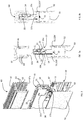
figure 3 is a perspective partially sectional view of the adapter infigure 1 during the assembly of a lighting apparatus in an electrified track; -
figures 3a-3e are sectional views that show three distinct operating installation steps of a lighting apparatus by the adapter infigure 1 ; -
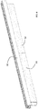
figure 4 is a perspective view of a pair of linear lighting apparatus mounted to an electrified track by adapters according to the present invention; -
figures 5 and 5a are perspective views showing in particular the engagement flaps of the adapter infigure 1 to the electrified track; -
figure 6 is a perspective view of a supplementary support accessory for the track used in the lighting unit according to the present invention. - In the following description, identical reference numerals or symbols are used for the illustration of the figures to indicate construction elements having the same function. Moreover, for clarity of illustration, some references may be not repeated in all the figures.
- With reference to the figures, there is shown a
lighting unit lighting apparatus 50 and anadapter 10 for supporting and electrically connecting such alighting apparatus 50 to anelectrified track 60. - In the embodiment shown by way of non-limiting example, the
lighting apparatus 50 comprises a profiledelement 52 which acts as a support of aLED light source 53. The profiledelement 52 of thelighting apparatus 50 further implements a pair of interface recesses 51 for connecting toadapter 10. - The electrified
track 60 shown comprises a profiledelement 62 provided with a plurality ofsub-profiles 61 projecting inwards, made of an insulating material for defining single housings for a plurality ofelectrical conductors 63. -
Adapter 10 for support and electrical connection comprises a box-like body 11 having an elongated conformation along an axis of development, which houses theelectronics 30 required for the power supply of thelighting apparatus 50 and an extraction andretraction mechanism 20 of a plurality ofelectrical contacts electronics 30 to theelectrical conductors 63 of the electrifiedtrack 60. Moreover, theground contact 26 projects above the box-like body 11, which when the adapter is inserted intotrack 60, contacts the profiledelement 62 of the same 60. - Through such a
mechanism 20, the box-like body 11 can assume a first compact configuration, in which theelectrical contacts figures 3a-3c ), and a second configuration in which theelectrical contacts figures 3d and 3e ). - As shown in
figure 1 , the box-like body 1 is associated with twointerface elements lighting apparatus 50 arranged mutually spaced apart with respect to the axis of development A. - In the embodiment shown, the
interface elements first portion like body 11 and asecond portion stem portion second portion end parts 12b', 13b' with a conformation complementary to the respective connection interfaces 51 provided on the profiledelement 52 of thelighting apparatus 50 so as to come into mutual engagement and therefore assume a support configuration of thelighting apparatus 50 by theinterface elements - The
interface elements like body 11. In particular, the retraction and extraction movements respectively cause the switching of the box-like body 11 from its first compact configuration to its second configuration withcontacts - To this end, the
first portion interface elements cam 14 that cooperates with the extraction andretraction mechanism 20 and determines the actuation thereof. In detail, in the embodiment shown, the extraction andretraction mechanism 20 comprises asupport element 24 that carries theelectrical contacts support flap 27 on a first side, and aprojection 25 on a second side transverse to the first, which engages withcam 14. - The coupling between
cam 14 andprojection 25 is such that a translation of theinterface element like body 11 determines a translation of thesupport element 24 in the transverse direction, making theelectrical contacts support flap 27 come out of the box-like body 11 through correspondingopenings 15, 15' made onsurface 11a of the same 11. - The box-
like body 11 comprises, on itsouter surface 11a, a plurality ofengagement flaps adapter 10 at least partially inserted into the electrifiedtrack 60, interfere with the plurality ofsub-profiles 61 inside saidtrack 60, resulting in a condition of first engagement between the two elements (engagement flaps figures 5 and 5a ,such engagement flaps adapter 10 fromtrack 60, despite the condition of engagement withsub-profiles 61 withintrack 60. - The
interface elements like body 11 provided with ahook 17a which, in non-use condition ofadapter 10, engages in a blockingopening 18 formed on theouter surface 11a of the box-like body 11. -
Hook 17a is maintained in the engagement position with the blockingopening 18 byelastic means 19 well shown infigure 3 . The blockingopening 18 is formed in such a position whereby, once the box-like body 11 is substantially entirely inserted in the electrifiedtrack 60,hook 17a is brought into a condition of disengagement with respect to such ablocking opening 18. In particular, alower wall 62a of the profiledelement 62 of the electrifiedtrack 60 that defines the inlet openinginside track 60 presses againsthook 17a protruding from the blockingopening 18, thus counteracting the action of theelastic means 19. This releases the possibility of translation of therespective interface element like body 11. - As better shown in
figure 6 , thelighting apparatus 50 comprises asupplementary support accessory 54 which, inserted into the profiledelement 52 of thelighting apparatus 50 and alongsideadapter 10 contributes to the support of the profiledelement 52 to track 60. - The operation of
adapter 10 for supporting and electrically connecting thelighting apparatus 50 to the electrifiedtrack 60 is as follows. - In the non-use condition shown in
figures 2a and3a , theinterface elements like body 11 and blocked to a relative translation with respect to such abody 11.Hook 17a is in fact engaged with the blockingopening 18. - By inserting the box-
like body 11 within the electrifiedtrack 60, as shown infigures 2b and3b ,hook 17a increasingly approaches the inlet opening withintrack 62 up to engage with thelower wall 62a of the profiledelement 62. In the configuration shown infigures 2b and3b , the engagement flaps 16a, 16b are engaged with sub-profiles 61, resulting in a first condition of engagement, although not fixed, ofadapter 10 within the electrifiedtrack 60. - As shown in
figure 3c , the interference betweenhook 17a and thelower wall 62a of the profiledelement 62 is such that thelower wall 62a presses againsthook 17a protruding from the blockingopening 18, thus counteracting the action of theelastic means 19. From this moment, a further pushing action by the installer causes the sliding of theinterface elements like body 11 shown infigure 3d , up to achieving the total insertion position shown infigures 2c and3e . - The sliding of the
interface elements like body 11 determines the activation of the extraction andretraction mechanism 20. In particular,projection 25 of thesupport element 24 is constrained to translate withincam 14 made on theinterface elements such elements support element 24 translate horizontally. In this way,contacts support element 24 in addition to the support flaps 27 protrude from the box-like body 11 through the correspondingopenings 15, 15'. The electrical connection ofadapter 10 to the electrifiedtrack 60, as well as the achievement of a stable engagement condition ofadapter 10 inside the electrifiedtrack 60 are thus obtained. - The features of the adapter for supporting and electrically connecting a lighting apparatus to an electrified track object of the present invention as well as the relevant advantages are clear from the above description.
- In fact, a single pushing action is sufficient for mounting, fastening and connecting the adapter. Moreover, it is not necessary to leave space for the movement of levers and the installation of multiple adjacent lighting apparatus can actually be obtained seamlessly, as shown in
figure 4 . - Additional variants of the embodiments described above are possible without departing from the teaching of the invention, the scope of which is defined by the appended claims.
- Finally, it is clear that several changes and variations may be made to an adapter for supporting and electrically connecting an electrified track thus conceived, all falling within the invention; moreover, all details can be replaced with technically equivalent elements. In the practice, the materials used as well as the sizes, can be whatever, according to the technical requirements.
Claims (10)
- Adapter (10) for supporting and electrically connecting a lighting apparatus (50) to an electrified track (60), comprising a box-like body (11) at whose interior a mechanism (20) is housed for extracting and retracting at least one electrical contact (21,22,23) such that the box-like body (11) is able to assume a first compact configuration, wherein the at least one electrical contact (21,22,23) is substantially housed inside the box-like body (11), and a second configuration wherein the at least one electrical contact (21,22,23) is at least partially extracted from the box-like body (11), the box-like body (11) being associated with at least one interface element (12,13) for coupling to a lighting apparatus (55) and is characterized in that the at least one interface element (12,13) is movable between a first extracted configuration and a second retracted configuration with respect to the box-like body (11), wherein the retraction and extraction movements respectively determine the passage of the box-like body (11) from its first compact configuration to its second extracted configuration and vice versa.
- Adapter (10) according to claim 1, wherein the at least one interface element (12,13) comprises a cam (14) that cooperates with the extraction and retraction mechanism (20) and determines the actuation thereof.
- Adapter (10) according to claim 1 or 2, wherein the extraction and retraction mechanism (20) comprises a support element (24) that carries the electrical contacts (21,22,23) on a first side and a projection (25) on a second side transverse to the first.
- Adapter (10) according to claim 2 and 3, wherein the projection (25) is engaged in the cam (14) such that a first translational movement in retraction and extraction of the at least one interface element (12,13) with respect to the box-like body (11) determines a second translational movement of the support element (24) along a direction transverse to the first movement.
- Adapter (10) according to claim 3 or 4, wherein the support element (24) carries a support flap (27) on the first side, said support flap (27) being able to assume a first configuration of full housing inside the box-like body (11) and a second configuration of at least partial extraction from the box-like body (11), the passage between the first and the second configuration of the support flap (27) being carried out through the movements of the at least one interface element (12,13) in retraction and extraction from the box-like body (11).
- Adapter (10) according to any one of the preceding claims, wherein the at least one interface element (12,13) comprises means (17) for blocking the translation with respect to the box-like body (11).
- Adapter (10) according to any one of the preceding claims, wherein the box-like body (11) comprises, on an outer surface thereof (11a), a plurality of engagement flaps (16a,16b) with an inner wall (61) of the electrified track (60), preferably with chamfered conformation.
- Lighting unit (10,50) comprising a lighting apparatus (50) preferably of the linear type, provided with a support element (52) and with at least one light source (53) constrained to the same (52), and an adapter (10) for supporting and electrically connecting the lighting apparatus (50) to an electrified track (60) characterized in that the adapter (10) is obtained according to any one of the preceding claims.
- Lighting unit (10,50) according to claim 8, wherein the support element (52) comprises at least one interface recess (51) for connecting to at least one end part (12b',13b') of the at least one interface element (12,13), the at least one recess (51) and the at least one end part (12b',13b') having complementary conformation.
- Lighting unit (10,50) according to claim 8 or 9, wherein the support element (52) comprises at least one supplementary support accessory (54) suitable for engagement in the electrified track (60).
Applications Claiming Priority (1)
| Application Number | Priority Date | Filing Date | Title |
|---|---|---|---|
| ITUA2016A001482A ITUA20161482A1 (en) | 2016-03-09 | 2016-03-09 | ADAPTER ADAPTED OF SUPPORT AND CONNECTION OF LIGHTING EQUIPMENT WITH ELECTRIFIED TRACKS AND LIGHTING GROUP EMPLOYING THE SAME |
Publications (2)
| Publication Number | Publication Date |
|---|---|
| EP3217090A1 EP3217090A1 (en) | 2017-09-13 |
| EP3217090B1 true EP3217090B1 (en) | 2018-12-12 |
Family
ID=56203578
Family Applications (1)
| Application Number | Title | Priority Date | Filing Date |
|---|---|---|---|
| EP17159913.7A Active EP3217090B1 (en) | 2016-03-09 | 2017-03-08 | Improved adapter for supporting and electrically connecting a lighting apparatus to an electrified track and lighting unit using the same |
Country Status (2)
| Country | Link |
|---|---|
| EP (1) | EP3217090B1 (en) |
| IT (1) | ITUA20161482A1 (en) |
Cited By (3)
| Publication number | Priority date | Publication date | Assignee | Title |
|---|---|---|---|---|
| EP4063727A1 (en) | 2021-03-25 | 2022-09-28 | H4X e.U. | Lighting assembly |
| EP4063718A1 (en) | 2021-03-25 | 2022-09-28 | H4X e.U. | Lighting arrangement and coupling unit for a lighting arrangement |
| DE102022204265A1 (en) | 2022-04-29 | 2023-11-02 | H4X E.U. | Adapter for use in a track lighting system and lighting arrangement |
Families Citing this family (8)
| Publication number | Priority date | Publication date | Assignee | Title |
|---|---|---|---|---|
| US11680702B2 (en) * | 2018-05-21 | 2023-06-20 | Exposure Illumination Architects, Inc. | Elongated modular heat sink with coupled light source |
| US12352421B2 (en) | 2018-05-21 | 2025-07-08 | Exposure Illumination Architects, Inc. | Orientation specific optics for elongated modular heat sink with coupled lamp |
| US12130000B2 (en) | 2018-05-21 | 2024-10-29 | Exposure Illumination Architects, Inc. | Elongated modular heat sink with coupled light source |
| IT201900005216A1 (en) * | 2019-04-05 | 2020-10-05 | A A G Stucchi S R L U S | Lamp, lighting fixture and related lighting system |
| EP3787375B1 (en) | 2019-08-30 | 2024-10-02 | Tridonic GmbH & Co. KG | Adapter for electrically connecting a lighting device to an electrical track |
| EP3786523B1 (en) | 2019-08-30 | 2022-03-09 | Tridonic GmbH & Co. KG | Adapter for electrically connecting a lighting device to an electrical track, lighting system comprising such an adapter and an electrical track |
| CN110762501B (en) * | 2019-10-12 | 2025-04-01 | 中山市叶子照明科技有限公司 | Track conductive line straight connector |
| IT201900023628A1 (en) * | 2019-12-11 | 2021-06-11 | A A G Stucchi S R L U S | Connection device suitable for different electrified guides |
Family Cites Families (5)
| Publication number | Priority date | Publication date | Assignee | Title |
|---|---|---|---|---|
| DE2104274A1 (en) * | 1970-02-03 | 1971-08-12 | Nokia Oy Ab | Connector |
| DE3013004C2 (en) * | 1980-04-03 | 1983-06-09 | Guralux Leuchten GmbH, 5860 Iserlohn | Electrical connector |
| DE3812586A1 (en) * | 1988-04-15 | 1989-11-02 | Staff Gmbh & Co Kg | Adaptor for busbars |
| US5855485A (en) * | 1997-01-16 | 1999-01-05 | Patti; Anthony G. | Multiple track adapter for track lighting systems |
| DE202013102943U1 (en) * | 2013-07-04 | 2014-07-07 | studio dinnebier Dinnebier Blieske GbR (vertretungsberechtigte Gesellschafter: Johannes Dinnebier, 13008 Berlin und Jan Blieske, 14195 Berlin) | Busbar adapter and arrangement with busbar adapter and busbar |
-
2016
- 2016-03-09 IT ITUA2016A001482A patent/ITUA20161482A1/en unknown
-
2017
- 2017-03-08 EP EP17159913.7A patent/EP3217090B1/en active Active
Non-Patent Citations (1)
| Title |
|---|
| None * |
Cited By (7)
| Publication number | Priority date | Publication date | Assignee | Title |
|---|---|---|---|---|
| EP4063727A1 (en) | 2021-03-25 | 2022-09-28 | H4X e.U. | Lighting assembly |
| EP4063718A1 (en) | 2021-03-25 | 2022-09-28 | H4X e.U. | Lighting arrangement and coupling unit for a lighting arrangement |
| DE102021202972A1 (en) | 2021-03-25 | 2022-09-29 | H4X E.U. | lighting arrangement |
| DE102021202975A1 (en) | 2021-03-25 | 2022-09-29 | H4X E.U. | Lighting arrangement and coupling unit for a lighting arrangement |
| DE102021202975B4 (en) | 2021-03-25 | 2025-03-13 | H4X E.U. | Lighting arrangement |
| DE102022204265A1 (en) | 2022-04-29 | 2023-11-02 | H4X E.U. | Adapter for use in a track lighting system and lighting arrangement |
| US12504157B2 (en) | 2022-04-29 | 2025-12-23 | H4X E.U. | Adapter for use in a track lighting system, and lighting arrangement |
Also Published As
| Publication number | Publication date |
|---|---|
| ITUA20161482A1 (en) | 2017-09-09 |
| EP3217090A1 (en) | 2017-09-13 |
Similar Documents
| Publication | Publication Date | Title |
|---|---|---|
| EP3217090B1 (en) | Improved adapter for supporting and electrically connecting a lighting apparatus to an electrified track and lighting unit using the same | |
| US9281645B2 (en) | Electrical supply connector with a simplified mounting arrangement | |
| US9564726B2 (en) | Electrical distribution system | |
| CN100514762C (en) | Sealed plug-in connection that runs through a dividing wall and corresponding mounting method | |
| CN107968297A (en) | Contact for plug connector | |
| CN111630317A (en) | Light strip system | |
| US6960090B2 (en) | Plug connector arrangement with latching actuation slide means | |
| CN114556719B (en) | Lamp or electrical unit for connection to a support rail | |
| NO329138B1 (en) | Lysstripesystem | |
| US7217008B2 (en) | Luminaire and method for changing a luminous means | |
| CN105723819A (en) | Component assembly system | |
| RU186710U1 (en) | BASE FOR MOUNTING THE LAMP TO THE GUIDE PROFILE | |
| CN114556710A (en) | Electrical device with locking device | |
| US10158205B2 (en) | Electric connector and illuminating device comprising the electric connector | |
| US12188644B2 (en) | Fastening device to secure a lighting assembly and lighting arrangement with at least one of this type of fastening device | |
| US20190296509A1 (en) | Busbar adapter, an arrangement with a busbar, and a method for connecting a busbar adapter in a busbar | |
| CN117918045B (en) | Electrical module for connection to a support rail and mating contact element | |
| US20180066817A1 (en) | Track head and track lamp | |
| CN108224369A (en) | Connect the plug assembly and track lamp of conductive guide | |
| EP3945642A1 (en) | Power socket having a base part, an aesthetic cover, and a drive member for a movable cover of the aesthetic cover | |
| WO2018076045A1 (en) | Assemblies and methods for detachably securing an electrical device to a support surface | |
| CN108779910A (en) | Electronic device for installation in a switchgear with a first fixing part and a second fixing part | |
| CN109038053B (en) | Plug connector with locking element | |
| CN114207954B (en) | Adapter for electrically connecting lighting equipment to an electrical track, including such adapter and a lighting system for the electrical track | |
| CN105580217A (en) | Housing device for an electrical connection terminal and electrical connection terminal |
Legal Events
| Date | Code | Title | Description |
|---|---|---|---|
| PUAI | Public reference made under article 153(3) epc to a published international application that has entered the european phase |
Free format text: ORIGINAL CODE: 0009012 |
|
| STAA | Information on the status of an ep patent application or granted ep patent |
Free format text: STATUS: THE APPLICATION HAS BEEN PUBLISHED |
|
| AK | Designated contracting states |
Kind code of ref document: A1 Designated state(s): AL AT BE BG CH CY CZ DE DK EE ES FI FR GB GR HR HU IE IS IT LI LT LU LV MC MK MT NL NO PL PT RO RS SE SI SK SM TR |
|
| AX | Request for extension of the european patent |
Extension state: BA ME |
|
| STAA | Information on the status of an ep patent application or granted ep patent |
Free format text: STATUS: REQUEST FOR EXAMINATION WAS MADE |
|
| 17P | Request for examination filed |
Effective date: 20180222 |
|
| RBV | Designated contracting states (corrected) |
Designated state(s): AL AT BE BG CH CY CZ DE DK EE ES FI FR GB GR HR HU IE IS IT LI LT LU LV MC MK MT NL NO PL PT RO RS SE SI SK SM TR |
|
| GRAP | Despatch of communication of intention to grant a patent |
Free format text: ORIGINAL CODE: EPIDOSNIGR1 |
|
| STAA | Information on the status of an ep patent application or granted ep patent |
Free format text: STATUS: GRANT OF PATENT IS INTENDED |
|
| RIC1 | Information provided on ipc code assigned before grant |
Ipc: F21S 8/00 20060101ALI20180607BHEP Ipc: F21V 21/35 20060101AFI20180607BHEP Ipc: F21Y 115/10 20160101ALN20180607BHEP Ipc: F21Y 101/00 20160101ALN20180607BHEP Ipc: H01R 25/14 20060101ALI20180607BHEP Ipc: F21V 23/06 20060101ALN20180607BHEP Ipc: F21Y 103/10 20160101ALN20180607BHEP |
|
| INTG | Intention to grant announced |
Effective date: 20180628 |
|
| GRAS | Grant fee paid |
Free format text: ORIGINAL CODE: EPIDOSNIGR3 |
|
| GRAA | (expected) grant |
Free format text: ORIGINAL CODE: 0009210 |
|
| STAA | Information on the status of an ep patent application or granted ep patent |
Free format text: STATUS: THE PATENT HAS BEEN GRANTED |
|
| AK | Designated contracting states |
Kind code of ref document: B1 Designated state(s): AL AT BE BG CH CY CZ DE DK EE ES FI FR GB GR HR HU IE IS IT LI LT LU LV MC MK MT NL NO PL PT RO RS SE SI SK SM TR |
|
| REG | Reference to a national code |
Ref country code: GB Ref legal event code: FG4D |
|
| REG | Reference to a national code |
Ref country code: CH Ref legal event code: EP |
|
| REG | Reference to a national code |
Ref country code: AT Ref legal event code: REF Ref document number: 1076518 Country of ref document: AT Kind code of ref document: T Effective date: 20181215 |
|
| REG | Reference to a national code |
Ref country code: DE Ref legal event code: R096 Ref document number: 602017001260 Country of ref document: DE |
|
| REG | Reference to a national code |
Ref country code: IE Ref legal event code: FG4D |
|
| REG | Reference to a national code |
Ref country code: NL Ref legal event code: MP Effective date: 20181212 |
|
| REG | Reference to a national code |
Ref country code: LT Ref legal event code: MG4D |
|
| PG25 | Lapsed in a contracting state [announced via postgrant information from national office to epo] |
Ref country code: ES Free format text: LAPSE BECAUSE OF FAILURE TO SUBMIT A TRANSLATION OF THE DESCRIPTION OR TO PAY THE FEE WITHIN THE PRESCRIBED TIME-LIMIT Effective date: 20181212 Ref country code: LT Free format text: LAPSE BECAUSE OF FAILURE TO SUBMIT A TRANSLATION OF THE DESCRIPTION OR TO PAY THE FEE WITHIN THE PRESCRIBED TIME-LIMIT Effective date: 20181212 Ref country code: NO Free format text: LAPSE BECAUSE OF FAILURE TO SUBMIT A TRANSLATION OF THE DESCRIPTION OR TO PAY THE FEE WITHIN THE PRESCRIBED TIME-LIMIT Effective date: 20190312 Ref country code: BG Free format text: LAPSE BECAUSE OF FAILURE TO SUBMIT A TRANSLATION OF THE DESCRIPTION OR TO PAY THE FEE WITHIN THE PRESCRIBED TIME-LIMIT Effective date: 20190312 Ref country code: HR Free format text: LAPSE BECAUSE OF FAILURE TO SUBMIT A TRANSLATION OF THE DESCRIPTION OR TO PAY THE FEE WITHIN THE PRESCRIBED TIME-LIMIT Effective date: 20181212 Ref country code: LV Free format text: LAPSE BECAUSE OF FAILURE TO SUBMIT A TRANSLATION OF THE DESCRIPTION OR TO PAY THE FEE WITHIN THE PRESCRIBED TIME-LIMIT Effective date: 20181212 |
|
| REG | Reference to a national code |
Ref country code: AT Ref legal event code: MK05 Ref document number: 1076518 Country of ref document: AT Kind code of ref document: T Effective date: 20181212 |
|
| PG25 | Lapsed in a contracting state [announced via postgrant information from national office to epo] |
Ref country code: RS Free format text: LAPSE BECAUSE OF FAILURE TO SUBMIT A TRANSLATION OF THE DESCRIPTION OR TO PAY THE FEE WITHIN THE PRESCRIBED TIME-LIMIT Effective date: 20181212 Ref country code: AL Free format text: LAPSE BECAUSE OF FAILURE TO SUBMIT A TRANSLATION OF THE DESCRIPTION OR TO PAY THE FEE WITHIN THE PRESCRIBED TIME-LIMIT Effective date: 20181212 Ref country code: SE Free format text: LAPSE BECAUSE OF FAILURE TO SUBMIT A TRANSLATION OF THE DESCRIPTION OR TO PAY THE FEE WITHIN THE PRESCRIBED TIME-LIMIT Effective date: 20181212 Ref country code: GR Free format text: LAPSE BECAUSE OF FAILURE TO SUBMIT A TRANSLATION OF THE DESCRIPTION OR TO PAY THE FEE WITHIN THE PRESCRIBED TIME-LIMIT Effective date: 20190313 |
|
| PG25 | Lapsed in a contracting state [announced via postgrant information from national office to epo] |
Ref country code: NL Free format text: LAPSE BECAUSE OF FAILURE TO SUBMIT A TRANSLATION OF THE DESCRIPTION OR TO PAY THE FEE WITHIN THE PRESCRIBED TIME-LIMIT Effective date: 20181212 |
|
| PG25 | Lapsed in a contracting state [announced via postgrant information from national office to epo] |
Ref country code: PL Free format text: LAPSE BECAUSE OF FAILURE TO SUBMIT A TRANSLATION OF THE DESCRIPTION OR TO PAY THE FEE WITHIN THE PRESCRIBED TIME-LIMIT Effective date: 20181212 Ref country code: IT Free format text: LAPSE BECAUSE OF FAILURE TO SUBMIT A TRANSLATION OF THE DESCRIPTION OR TO PAY THE FEE WITHIN THE PRESCRIBED TIME-LIMIT Effective date: 20181212 Ref country code: CZ Free format text: LAPSE BECAUSE OF FAILURE TO SUBMIT A TRANSLATION OF THE DESCRIPTION OR TO PAY THE FEE WITHIN THE PRESCRIBED TIME-LIMIT Effective date: 20181212 Ref country code: PT Free format text: LAPSE BECAUSE OF FAILURE TO SUBMIT A TRANSLATION OF THE DESCRIPTION OR TO PAY THE FEE WITHIN THE PRESCRIBED TIME-LIMIT Effective date: 20190412 |
|
| PG25 | Lapsed in a contracting state [announced via postgrant information from national office to epo] |
Ref country code: RO Free format text: LAPSE BECAUSE OF FAILURE TO SUBMIT A TRANSLATION OF THE DESCRIPTION OR TO PAY THE FEE WITHIN THE PRESCRIBED TIME-LIMIT Effective date: 20181212 Ref country code: SK Free format text: LAPSE BECAUSE OF FAILURE TO SUBMIT A TRANSLATION OF THE DESCRIPTION OR TO PAY THE FEE WITHIN THE PRESCRIBED TIME-LIMIT Effective date: 20181212 Ref country code: SM Free format text: LAPSE BECAUSE OF FAILURE TO SUBMIT A TRANSLATION OF THE DESCRIPTION OR TO PAY THE FEE WITHIN THE PRESCRIBED TIME-LIMIT Effective date: 20181212 Ref country code: EE Free format text: LAPSE BECAUSE OF FAILURE TO SUBMIT A TRANSLATION OF THE DESCRIPTION OR TO PAY THE FEE WITHIN THE PRESCRIBED TIME-LIMIT Effective date: 20181212 Ref country code: IS Free format text: LAPSE BECAUSE OF FAILURE TO SUBMIT A TRANSLATION OF THE DESCRIPTION OR TO PAY THE FEE WITHIN THE PRESCRIBED TIME-LIMIT Effective date: 20190412 |
|
| REG | Reference to a national code |
Ref country code: DE Ref legal event code: R097 Ref document number: 602017001260 Country of ref document: DE |
|
| PLBE | No opposition filed within time limit |
Free format text: ORIGINAL CODE: 0009261 |
|
| STAA | Information on the status of an ep patent application or granted ep patent |
Free format text: STATUS: NO OPPOSITION FILED WITHIN TIME LIMIT |
|
| PG25 | Lapsed in a contracting state [announced via postgrant information from national office to epo] |
Ref country code: SI Free format text: LAPSE BECAUSE OF FAILURE TO SUBMIT A TRANSLATION OF THE DESCRIPTION OR TO PAY THE FEE WITHIN THE PRESCRIBED TIME-LIMIT Effective date: 20181212 Ref country code: DK Free format text: LAPSE BECAUSE OF FAILURE TO SUBMIT A TRANSLATION OF THE DESCRIPTION OR TO PAY THE FEE WITHIN THE PRESCRIBED TIME-LIMIT Effective date: 20181212 Ref country code: AT Free format text: LAPSE BECAUSE OF FAILURE TO SUBMIT A TRANSLATION OF THE DESCRIPTION OR TO PAY THE FEE WITHIN THE PRESCRIBED TIME-LIMIT Effective date: 20181212 Ref country code: MC Free format text: LAPSE BECAUSE OF FAILURE TO SUBMIT A TRANSLATION OF THE DESCRIPTION OR TO PAY THE FEE WITHIN THE PRESCRIBED TIME-LIMIT Effective date: 20181212 |
|
| 26N | No opposition filed |
Effective date: 20190913 |
|
| PG25 | Lapsed in a contracting state [announced via postgrant information from national office to epo] |
Ref country code: LU Free format text: LAPSE BECAUSE OF NON-PAYMENT OF DUE FEES Effective date: 20190308 |
|
| PG25 | Lapsed in a contracting state [announced via postgrant information from national office to epo] |
Ref country code: IE Free format text: LAPSE BECAUSE OF NON-PAYMENT OF DUE FEES Effective date: 20190308 |
|
| PG25 | Lapsed in a contracting state [announced via postgrant information from national office to epo] |
Ref country code: TR Free format text: LAPSE BECAUSE OF FAILURE TO SUBMIT A TRANSLATION OF THE DESCRIPTION OR TO PAY THE FEE WITHIN THE PRESCRIBED TIME-LIMIT Effective date: 20181212 |
|
| PG25 | Lapsed in a contracting state [announced via postgrant information from national office to epo] |
Ref country code: MT Free format text: LAPSE BECAUSE OF NON-PAYMENT OF DUE FEES Effective date: 20190308 |
|
| REG | Reference to a national code |
Ref country code: CH Ref legal event code: PL |
|
| PG25 | Lapsed in a contracting state [announced via postgrant information from national office to epo] |
Ref country code: LI Free format text: LAPSE BECAUSE OF NON-PAYMENT OF DUE FEES Effective date: 20200331 Ref country code: CH Free format text: LAPSE BECAUSE OF NON-PAYMENT OF DUE FEES Effective date: 20200331 |
|
| PG25 | Lapsed in a contracting state [announced via postgrant information from national office to epo] |
Ref country code: CY Free format text: LAPSE BECAUSE OF FAILURE TO SUBMIT A TRANSLATION OF THE DESCRIPTION OR TO PAY THE FEE WITHIN THE PRESCRIBED TIME-LIMIT Effective date: 20181212 |
|
| PG25 | Lapsed in a contracting state [announced via postgrant information from national office to epo] |
Ref country code: HU Free format text: LAPSE BECAUSE OF FAILURE TO SUBMIT A TRANSLATION OF THE DESCRIPTION OR TO PAY THE FEE WITHIN THE PRESCRIBED TIME-LIMIT; INVALID AB INITIO Effective date: 20170308 |
|
| PG25 | Lapsed in a contracting state [announced via postgrant information from national office to epo] |
Ref country code: MK Free format text: LAPSE BECAUSE OF FAILURE TO SUBMIT A TRANSLATION OF THE DESCRIPTION OR TO PAY THE FEE WITHIN THE PRESCRIBED TIME-LIMIT Effective date: 20181212 |
|
| P01 | Opt-out of the competence of the unified patent court (upc) registered |
Effective date: 20230517 |
|
| PGFP | Annual fee paid to national office [announced via postgrant information from national office to epo] |
Ref country code: GB Payment date: 20260324 Year of fee payment: 10 |
|
| PGFP | Annual fee paid to national office [announced via postgrant information from national office to epo] |
Ref country code: DE Payment date: 20260319 Year of fee payment: 10 |
|
| PGFP | Annual fee paid to national office [announced via postgrant information from national office to epo] |
Ref country code: FI Payment date: 20260323 Year of fee payment: 10 Ref country code: BE Payment date: 20260319 Year of fee payment: 10 |
|
| PGFP | Annual fee paid to national office [announced via postgrant information from national office to epo] |
Ref country code: FR Payment date: 20260320 Year of fee payment: 10 |