EP3217123A1 - Klimatisierungs-/heisswasserversorgungssystem - Google Patents
Klimatisierungs-/heisswasserversorgungssystem Download PDFInfo
- Publication number
- EP3217123A1 EP3217123A1 EP17157736.4A EP17157736A EP3217123A1 EP 3217123 A1 EP3217123 A1 EP 3217123A1 EP 17157736 A EP17157736 A EP 17157736A EP 3217123 A1 EP3217123 A1 EP 3217123A1
- Authority
- EP
- European Patent Office
- Prior art keywords
- refrigerant
- hot water
- air
- supply
- heat exchanger
- Prior art date
- Legal status (The legal status is an assumption and is not a legal conclusion. Google has not performed a legal analysis and makes no representation as to the accuracy of the status listed.)
- Withdrawn
Links
- 238000004378 air conditioning Methods 0.000 title claims abstract description 167
- 239000003507 refrigerant Substances 0.000 claims abstract description 473
- 238000005057 refrigeration Methods 0.000 claims abstract description 155
- 238000010438 heat treatment Methods 0.000 claims description 132
- 238000009833 condensation Methods 0.000 abstract description 67
- 230000005494 condensation Effects 0.000 abstract description 67
- 230000001771 impaired effect Effects 0.000 abstract description 7
- CURLTUGMZLYLDI-UHFFFAOYSA-N Carbon dioxide Chemical compound O=C=O CURLTUGMZLYLDI-UHFFFAOYSA-N 0.000 description 126
- 229910002092 carbon dioxide Inorganic materials 0.000 description 63
- 239000001569 carbon dioxide Substances 0.000 description 63
- 230000020169 heat generation Effects 0.000 description 63
- 239000007788 liquid Substances 0.000 description 51
- XLYOFNOQVPJJNP-UHFFFAOYSA-N water Substances O XLYOFNOQVPJJNP-UHFFFAOYSA-N 0.000 description 36
- 238000001816 cooling Methods 0.000 description 35
- 230000007704 transition Effects 0.000 description 29
- 229910052799 carbon Inorganic materials 0.000 description 18
- 230000009467 reduction Effects 0.000 description 17
- 238000010586 diagram Methods 0.000 description 16
- 239000000463 material Substances 0.000 description 9
- 238000001704 evaporation Methods 0.000 description 8
- 239000010726 refrigerant oil Substances 0.000 description 8
- 230000006835 compression Effects 0.000 description 7
- 238000007906 compression Methods 0.000 description 7
- RYGMFSIKBFXOCR-UHFFFAOYSA-N Copper Chemical compound [Cu] RYGMFSIKBFXOCR-UHFFFAOYSA-N 0.000 description 6
- 239000010949 copper Substances 0.000 description 6
- 229910052802 copper Inorganic materials 0.000 description 6
- 239000011810 insulating material Substances 0.000 description 6
- 238000004804 winding Methods 0.000 description 6
- 239000011248 coating agent Substances 0.000 description 5
- 238000000576 coating method Methods 0.000 description 5
- 230000006866 deterioration Effects 0.000 description 5
- 238000004519 manufacturing process Methods 0.000 description 5
- 238000000034 method Methods 0.000 description 5
- 239000003921 oil Substances 0.000 description 5
- 230000001133 acceleration Effects 0.000 description 4
- 230000008020 evaporation Effects 0.000 description 4
- 230000008569 process Effects 0.000 description 4
- 239000011347 resin Substances 0.000 description 4
- 229920005989 resin Polymers 0.000 description 4
- 230000007423 decrease Effects 0.000 description 3
- 239000003651 drinking water Substances 0.000 description 3
- 235000020188 drinking water Nutrition 0.000 description 3
- 239000012530 fluid Substances 0.000 description 3
- XEEYBQQBJWHFJM-UHFFFAOYSA-N Iron Chemical compound [Fe] XEEYBQQBJWHFJM-UHFFFAOYSA-N 0.000 description 2
- 238000004364 calculation method Methods 0.000 description 2
- 230000008859 change Effects 0.000 description 2
- 238000005299 abrasion Methods 0.000 description 1
- 230000002528 anti-freeze Effects 0.000 description 1
- 238000006243 chemical reaction Methods 0.000 description 1
- 238000004891 communication Methods 0.000 description 1
- 230000009977 dual effect Effects 0.000 description 1
- 238000005516 engineering process Methods 0.000 description 1
- 229920006248 expandable polystyrene Polymers 0.000 description 1
- 238000009434 installation Methods 0.000 description 1
- 229910052742 iron Inorganic materials 0.000 description 1
- 230000014759 maintenance of location Effects 0.000 description 1
- 230000007246 mechanism Effects 0.000 description 1
Images


Classifications
-
- F—MECHANICAL ENGINEERING; LIGHTING; HEATING; WEAPONS; BLASTING
- F25—REFRIGERATION OR COOLING; COMBINED HEATING AND REFRIGERATION SYSTEMS; HEAT PUMP SYSTEMS; MANUFACTURE OR STORAGE OF ICE; LIQUEFACTION SOLIDIFICATION OF GASES
- F25B—REFRIGERATION MACHINES, PLANTS OR SYSTEMS; COMBINED HEATING AND REFRIGERATION SYSTEMS; HEAT PUMP SYSTEMS
- F25B49/00—Arrangement or mounting of control or safety devices
- F25B49/02—Arrangement or mounting of control or safety devices for compression type machines, plants or systems
-
- F—MECHANICAL ENGINEERING; LIGHTING; HEATING; WEAPONS; BLASTING
- F24—HEATING; RANGES; VENTILATING
- F24F—AIR-CONDITIONING; AIR-HUMIDIFICATION; VENTILATION; USE OF AIR CURRENTS FOR SCREENING
- F24F5/00—Air-conditioning systems or apparatus not covered by F24F1/00 or F24F3/00, e.g. using solar heat or combined with household units such as an oven or water heater
- F24F5/0096—Air-conditioning systems or apparatus not covered by F24F1/00 or F24F3/00, e.g. using solar heat or combined with household units such as an oven or water heater combined with domestic apparatus
-
- F—MECHANICAL ENGINEERING; LIGHTING; HEATING; WEAPONS; BLASTING
- F24—HEATING; RANGES; VENTILATING
- F24D—DOMESTIC- OR SPACE-HEATING SYSTEMS, e.g. CENTRAL HEATING SYSTEMS; DOMESTIC HOT-WATER SUPPLY SYSTEMS; ELEMENTS OR COMPONENTS THEREFOR
- F24D17/00—Domestic hot-water supply systems
- F24D17/02—Domestic hot-water supply systems using heat pumps
-
- F—MECHANICAL ENGINEERING; LIGHTING; HEATING; WEAPONS; BLASTING
- F25—REFRIGERATION OR COOLING; COMBINED HEATING AND REFRIGERATION SYSTEMS; HEAT PUMP SYSTEMS; MANUFACTURE OR STORAGE OF ICE; LIQUEFACTION SOLIDIFICATION OF GASES
- F25B—REFRIGERATION MACHINES, PLANTS OR SYSTEMS; COMBINED HEATING AND REFRIGERATION SYSTEMS; HEAT PUMP SYSTEMS
- F25B25/00—Machines, plants or systems, using a combination of modes of operation covered by two or more of the groups F25B1/00 - F25B23/00
- F25B25/005—Machines, plants or systems, using a combination of modes of operation covered by two or more of the groups F25B1/00 - F25B23/00 using primary and secondary systems
-
- F—MECHANICAL ENGINEERING; LIGHTING; HEATING; WEAPONS; BLASTING
- F25—REFRIGERATION OR COOLING; COMBINED HEATING AND REFRIGERATION SYSTEMS; HEAT PUMP SYSTEMS; MANUFACTURE OR STORAGE OF ICE; LIQUEFACTION SOLIDIFICATION OF GASES
- F25B—REFRIGERATION MACHINES, PLANTS OR SYSTEMS; COMBINED HEATING AND REFRIGERATION SYSTEMS; HEAT PUMP SYSTEMS
- F25B7/00—Compression machines, plants or systems, with cascade operation, i.e. with two or more circuits, the heat from the condenser of one circuit being absorbed by the evaporator of the next circuit
-
- F—MECHANICAL ENGINEERING; LIGHTING; HEATING; WEAPONS; BLASTING
- F25—REFRIGERATION OR COOLING; COMBINED HEATING AND REFRIGERATION SYSTEMS; HEAT PUMP SYSTEMS; MANUFACTURE OR STORAGE OF ICE; LIQUEFACTION SOLIDIFICATION OF GASES
- F25B—REFRIGERATION MACHINES, PLANTS OR SYSTEMS; COMBINED HEATING AND REFRIGERATION SYSTEMS; HEAT PUMP SYSTEMS
- F25B2313/00—Compression machines, plants or systems with reversible cycle not otherwise provided for
- F25B2313/023—Compression machines, plants or systems with reversible cycle not otherwise provided for using multiple indoor units
- F25B2313/0233—Compression machines, plants or systems with reversible cycle not otherwise provided for using multiple indoor units in parallel arrangements
-
- F—MECHANICAL ENGINEERING; LIGHTING; HEATING; WEAPONS; BLASTING
- F25—REFRIGERATION OR COOLING; COMBINED HEATING AND REFRIGERATION SYSTEMS; HEAT PUMP SYSTEMS; MANUFACTURE OR STORAGE OF ICE; LIQUEFACTION SOLIDIFICATION OF GASES
- F25B—REFRIGERATION MACHINES, PLANTS OR SYSTEMS; COMBINED HEATING AND REFRIGERATION SYSTEMS; HEAT PUMP SYSTEMS
- F25B2339/00—Details of evaporators; Details of condensers
- F25B2339/04—Details of condensers
- F25B2339/047—Water-cooled condensers
-
- F—MECHANICAL ENGINEERING; LIGHTING; HEATING; WEAPONS; BLASTING
- F25—REFRIGERATION OR COOLING; COMBINED HEATING AND REFRIGERATION SYSTEMS; HEAT PUMP SYSTEMS; MANUFACTURE OR STORAGE OF ICE; LIQUEFACTION SOLIDIFICATION OF GASES
- F25B—REFRIGERATION MACHINES, PLANTS OR SYSTEMS; COMBINED HEATING AND REFRIGERATION SYSTEMS; HEAT PUMP SYSTEMS
- F25B2500/00—Problems to be solved
- F25B2500/01—Geometry problems, e.g. for reducing size
Definitions
- the present invention relates to an indoor unit of an air conditioner, and specifically relates to an air-conditioning/hot water-supply system capable of simultaneously supplying hot/cool heat necessary for air cooling, air heating and hot water supply, in which a refrigeration cycle for generating hot water for hot water supply is installed and heat exchange is performed between an air-conditioning refrigerant and a hot water-supply refrigerant via a cascade heat exchanger.
- a refrigeration cycle in which an air-conditioning refrigerant circulates and a refrigeration cycle in which a hot water-supply refrigerant circulates form what is called a dual refrigeration cycle in which these refrigeration cycles are thermally connected in a cascade heat exchanger.
- an upper limit use temperature for the temperature of the discharged refrigerant from the hot water-supply compressor is generally set to 110°C.
- a condensation temperature Tvc in a refrigeration cycle in which an air-conditioning refrigerant circulates is 30°C to 55°C.
- a suction superheat degree in a hot water-supply compressor is set as 5 K, which does not cause a liquid backflow that impairs a reliability of the compressor and provides high performance of the refrigeration cycle, that is, is set so that a suction temperature in the compressor is 25°C.
- a temperature of a heating medium to be supplied to a hot water-supply heat exchanger is set in a range of 5 to 30°C, and a temperature difference between the carbon dioxide and the hot water-supply heating medium is set as 10 K, and thus the temperature of the carbon dioxide at an exit of a refrigerant flow passage in the hot water-supply heat exchanger is 15 to 40°C.
- the sucked refrigerant in the hot water-supply compressor has a pressure of 5.7 MPa, a temperature of 25°C and a density of 170 kg/m3, and after compression in an isenthalpic change by hot water-supply compressor, the discharged refrigerant has a pressure of 15.0 MPa and a density of 332 kg/m3 at a temperature Td of 100°C.
- the operation is controlled so that the evaporating pressure Pe in the refrigeration cycle in which the carbon dioxide circulates is no more than 7.4 MPa.
- the temperature of the heating medium supplied to the hot water-supply heat exchanger is set in a range of 5 to 30°C and the temperature difference between the carbon dioxide and the heating medium for hot water supply is set to 10K, the temperature of the carbon dioxide at the exit of the refrigerant flow passage in the hot water-supply heat exchanger is 15 to 40°C.
- a high pressure in the hot water supply cycle is approximately 13 MPa, and the carbon dioxide at the exit of the refrigerant flow passage in the hot water-supply heat exchanger is subjected to pressure reduction in an isenthalpic change to a low pressure of 7.4 MPa by a carbon dioxide flow adjustment valve and flows into a cascade heat exchanger, and the temperature of the carbon dioxide here is 12 to 30°C.
- the condensation temperature Tvc of the air-conditioning refrigerant flowing in the cascade heat exchanger is 55°C and the temperature of the carbon dioxide flowing into the cascade heat exchanger is 12 to 30°C, and thus, the temperature of the carbon dioxide flowing out from the cascade heat exchanger is 52 to 54°C.
- the sucked refrigerant in the hot water-supply compressor 310 has a pressure of 7.4 MPa, has a temperature of 52 to 54°C and a density of 179 to 183 kg/m 3
- the discharged refrigerant from the hot water-supply compressor 310 has a pressure of 12.8 to 13.2 MPa and a density of 266 to 276 kg/m 3 at a temperature Td of 100°C.
- the density of the sucked refrigerant in the hot water-supply compressor when the condensation temperature Tvc in the refrigeration cycle in which the air-conditioning refrigerant circulates is 30°C is low compared to the density of the sucked refrigerant in the hot water-supply compressor when the condensation temperature Tvc is 55°C.
- the density of the discharged refrigerant from the hot water-supply compressor when the condensation temperature Tvc in the refrigeration cycle in which the air-conditioning refrigerant circulates is 30°C is high compared to the density of the discharged refrigerant from the hot water-supply compressor when the condensation temperature Tvc is 55°C.
- the temperature of the discharged refrigerant from the hot water-supply compressor may increase beyond 100°C, resulting in a problem of a durability of the compressor being impaired because of, e.g., acceleration of, e.g., deterioration of a motor winding coating in the hot water-supply compressor.
- an amount of the refrigerant charged in the entire circuit is substantially determined by the product of the high pressure-side circuit internal volume and the density of the discharged refrigerant from the hot water-supply compressor.
- the condensation temperature Tvc in the refrigeration cycle in which the air-conditioning refrigerant circulates is 30°C and the temperature of the discharged refrigerant from the hot water-supply compressor is 100°C
- the condensation temperature Tvc sharply increases to 55°C because of, e.g., reduction in number of operating indoor machines connected to the refrigeration cycle in which the air-conditioning refrigerant circulates will be considered.
- the condensation temperature Tvc varies from 30°C to 55°C, if an attempt is made to maintain the temperature of the discharged refrigerant at 100°C, as mentioned above, the density of the discharged refrigerant from the hot water-supply compressor 310 becomes relatively low compared to that in the case where the condensation temperature Tvc is 30°C, resulting in an excess of refrigerant in the refrigeration cycle in which the carbon dioxide circulates.
- the high pressure is increased, and the temperature of the discharged refrigerant from the hot water-supply compressor increases beyond 110°C, which is a design limit, resulting in impairing the durability of the compressor because of acceleration of deterioration of, e.g., the refrigerant oil enclosed in the hot water-supply compressor and an insulating coating of a winding of the motor.
- the amount of refrigerant charged in the entire circuit is substantially determined by the product of the low pressure-side circuit internal volume and the density of the sucked refrigerant in the hot water-supply compressor.
- the condensation temperature Tvc in the refrigeration cycle in which the air-conditioning refrigerant circulates is 55°C and the temperature of the discharged refrigerant from the hot water-supply compressor is 100°C
- the condensation temperature Tvc sharply decreases to 30°C because of, e.g., reduction in number of operating indoor machines connected to the refrigeration cycle in which the air-conditioning refrigerant circulates.
- the condensation temperature Tvc varies from 55°C to 30°C, if an attempt is made to maintain the temperature of the discharged refrigerant at 100°C, as mentioned above, the density of the sucked refrigerant in the hot water-supply compressor becomes relatively low compared to that in the case where the condensation temperature Tvc is 55°C, resulting in an excess of refrigerant in the refrigeration cycle in which the carbon dioxide circulates.
- the high pressure is increased, and the temperature of the discharged refrigerant from the hot water-supply compressor increases beyond 110°C, which is a design limit, resulting in impairing the durability of the compressor because of acceleration of deterioration of, e.g., the refrigerant oil enclosed in the hot water-supply compressor and an insulating coating of a winding of the motor.
- the present invention is intended to solve the aforementioned problem, and an object of the present invention is to provide an air-conditioning/hot water-supply system that, even if a condensation temperature Tvc in a refrigeration cycle in which an air-conditioning refrigerant circulates varies, prevents a durability of a hot water-supply compressor from being impaired, enabling enhancement in reliability.
- the present invention provides an air-conditioning/hot water-supply system including: a first refrigeration cycle including a hot water-supply compressor that compresses a hot water-supply refrigerant, a hot water-supply heat exchanger that allows heat exchange between the hot water-supply refrigerant and a hot water-supply heating medium, and a cascade heat exchanger that allows heat exchange between the hot water-supply refrigerant and an air-conditioning refrigerant; and a second refrigeration cycle including a first circuit in which the cascade heat exchanger and a second refrigerant flow control device that controls a flow of the air-conditioning refrigerant to be supplied to the cascade heat exchanger are serially connected and at least one second circuit in which an indoor heat exchanger that allows heat exchange between the air-conditioning refrigerant and indoor air and a third refrigerant flow control device that controls a flow of the air-conditioning refrigerant to be supplied to the indoor heat exchanger are serially connected,
- the volume ratio between the low pressure-side circuit internal volume Ve and the high pressure-side circuit internal volume Vc in the first refrigeration cycle is set in a proper range so that the discharge temperature Td from the first refrigeration cycle falls within a range of 100 to 110°C at any condensation temperature Tvc in the second refrigeration cycle where the condensation temperature Tvc varies in a range of 30°C to 55°C.
- a first aspect of the present invention provides an air-conditioning/hot water-supply system including: a first refrigeration cycle including a hot water-supply compressor that compresses a hot water-supply refrigerant, a hot water-supply heat exchanger that allows heat exchange between the hot water-supply refrigerant and a hot water-supply heating medium, and a cascade heat exchanger that allows heat exchange between the hot water-supply refrigerant and an air-conditioning refrigerant; and a second refrigeration cycle including a first circuit in which the cascade heat exchanger and a second refrigerant flow control device that controls a flow of the air-conditioning refrigerant to be supplied to the cascade heat exchanger are serially connected and at least one second circuit in which an indoor heat exchanger that allows heat exchange between the air-conditioning refrigerant and indoor air and a third refrigerant flow control device that controls a flow of the air-conditioning refrigerant to be supplied to the indoor heat exchanger are serially connected, the second refrigeration
- the volume ratio between the low pressure-side circuit internal volume Ve and the high pressure-side circuit internal volume Vc in the first refrigeration cycle is made to fall within a proper range, whereby a discharge temperature Td in the first refrigeration cycle falls within a range of 100 to 110°C at any condensation temperature Tvc in the second refrigeration cycle where the condensation temperature Tvc varies in a range of 30°C to 55°C.
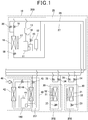
- FIG. 1 is a diagram of a cycle configuration of an air-conditioning/hot water-supply system according to an embodiment of the present invention.
- the air-conditioning/hot water-supply system illustrated in FIG. 1 includes an outdoor unit 10, indoor machines 30 and a heat generation unit 40.
- the present embodiment employs a configuration in which two indoor machines 30 and one heat generation unit 40 are connected to one outdoor unit 10 respectively.
- the refrigeration cycle configuration is not limited to the one illustrated in FIG. 1 .
- two or more outdoor units 10, one or three or more indoor machines 30 and two or more heat generation units 40 can be connected in parallel.
- the outdoor unit 10, the indoor machines 30 and the heat generation unit 40 are connected via a piping in which an air-conditioning refrigerant circulates.
- the outdoor unit 10 and the indoor machines 30 are connected via a gas pipe 25 in which the high-temperature, high-pressure gasified air-conditioning refrigerant flows, a suction pipe 26 in which the low-pressure air-conditioning refrigerant flows and a liquid pipe 27 in which the high-pressure liquefied air-conditioning refrigerant flows. If there are two indoor machines 30 as illustrated in FIG. 1 , the indoor machines 30 are parallelly connected to the three pipings. On the other hand, the outdoor unit 10 and the heat generation unit 40, which are parallelly connected to pipes like the indoor machines 30, are, however, connected via the gas pipe 25 and the liquid pipe 27.
- the outdoor unit 10 includes an air-conditioning compressor 11 that compresses an air-conditioning refrigerant.
- An accumulator 12 that supplies a gas refrigerant to the air-conditioning compressor 11 is connected to the suction side of the air-conditioning compressor 11.
- An oil separator 13 that separates a refrigerant oil contained in a gaseous air-conditioning refrigerant to be discharged is connected to the discharge side of the air-conditioning compressor 11.
- the refrigerant oil separated from the air-conditioning refrigerant by the oil separator 13 is returned to the air-conditioning compressor 11 via an oil return pipe 14. Communication with the oil return pipe 14 is controlled by opening/closing of an oil return pipe opening/closing valve 15.
- the outdoor unit 10 includes an outdoor heat exchanger 16, and in the vicinity of the outdoor heat exchanger 16, an outdoor fan 17 that supplies air around the outdoor unit 10 to the outdoor heat exchanger 16 is provided.
- the outdoor heat exchanger 16 is configured so that heat exchange is performed between air sent by the outdoor fan 17 and the air-conditioning refrigerant, and for the outdoor heat exchanger 16, in general, a fin tube-type or microtube-type heat exchanger is employed.
- the outdoor unit 10 includes an outdoor refrigerant flow adjustment valve 18 that adjusts a flow of the air-conditioning refrigerant to be supplied to the outdoor heat exchanger 16, an outdoor gas pipe opening/closing valve 19 that controls a flow of the air-conditioning refrigerant in the gas pipe 25, and an outdoor suction pipe opening/closing valve 20 that controls a flow of the air-conditioning refrigerant in the suction pipe 26.
- Each indoor machine 30 includes an indoor heat exchanger 31, an indoor fan 32 that supplies air around the indoor machine 30 to the indoor heat exchanger 31, and an indoor refrigerant flow adjustment valve 33 (third refrigerant flow control device) that adjusts a flow of the air-conditioning refrigerant to be supplied to the indoor heat exchanger 31.
- the indoor heat exchanger 31 is configured so that heat exchange is performed between air sent by the indoor fan 32 and the air-conditioning refrigerant, and for the indoor heat exchanger 31, in general, a fin tube-type or microtube-type heat exchanger is employed.
- each indoor machine 30 includes an indoor gas pipe opening/closing valve 34 that controls whether or not the air-conditioning refrigerant flows from the gas pipe 25, and an indoor suction pipe opening/closing valve 35 that controls whether or not the air-conditioning refrigerant flows to the suction pipe 26.
- the heat generation unit 40 includes a hot water-supply compressor 41 that compresses a hot water-supply refrigerant, a hot water-supply heat exchanger 42 that allows heat exchange between the hot water-supply refrigerant and a heating medium containing water as a main component, and a hot water-supply refrigerant flow adjustment valve 43 that adjusts a flow of the hot water-supply refrigerant.
- the heat generation unit 40 includes a cascade heat exchanger 44 in which heat exchange is performed between the air-conditioning refrigerant supplied from the gas pipe 25 and the hot water-supply refrigerant, a heat generation unit refrigerant flow adjustment valve 45 (second refrigerant flow control device) that adjusts a flow of the air-conditioning refrigerant to be supplied to the cascade heat exchanger 44, and a heating medium pump 46 that supplies the heating medium to the hot water-supply heat exchanger 42.
- a cascade heat exchanger 44 in which heat exchange is performed between the air-conditioning refrigerant supplied from the gas pipe 25 and the hot water-supply refrigerant
- a heat generation unit refrigerant flow adjustment valve 45 second refrigerant flow control device
- the heating medium boiled up to 70 to 90°C by the hot water-supply heat exchanger 42 is stored in a hot water storage tank (not illustrated). If the heating medium is drinking water, the heating medium is directly used for hot water supply. On the other hand, if the heating medium is not drinking water such as an antifreeze liquid, the heating medium is supplied to, e.g., a radiator installed indoors for use in air heating or the heating medium delivers heat to drinking water in the hot water storage tank and thus is used for hot water supply.
- a first refrigeration cycle 100 is configured by connecting the hot water-supply compressor 41, the hot water-supply heat exchanger 42, the hot water-supply refrigerant flow adjustment valve 43 and the cascade heat exchanger 44 in a loop.
- a second refrigeration cycle 200 includes a first circuit 201 in which the cascade heat exchanger 44 and the heat generation unit refrigerant flow adjustment valve 45 are serially connected, and at least one second circuit 202 in which the indoor heat exchanger 31 and the indoor refrigerant flow adjustment valve 33 that controls the flow of the air conditioning refrigerant to be supplied to the indoor heat exchanger 31 are serially connected, and is configured by connecting a heat load circuit in which the first circuit 201 and the second circuit 202 are parallelly connected, to the air-conditioning compressor 11 and the outdoor heat exchanger 16.
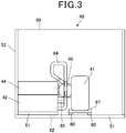
- FIG. 2 is a plan view illustrating the inner structure of the heat generation unit 40 in the present embodiment
- FIG. 3 is a front view illustrating the inner structure of the heat generation unit 40.
- a refrigeration cycle formed by the hot water-supply compressor 41, the hot water-supply heat exchanger 42, the hot water-supply refrigerant flow adjustment valve 43 and the cascade heat exchanger 44, the heat generation unit refrigerant flow adjustment valve 45 and the heating medium pump 46 are housed in the casing 50.
- a double pipe-type heat exchanger is a heat exchanger formed by inserting at least one pipe (inner pipe) into a tube (outer pipe) having a rough circular cross-sectional shape. If there are a plurality of inner pipes, the inner pipes are helically twisted and inserted into the outer pipe. If a carbon dioxide refrigerant is used for the hot water-supply refrigerant, the carbon dioxide refrigerant is made to flow in the inner pipe of the hot water-supply heat exchanger 42 and the heating medium is made to flow between the outer pipe and the inner pipe.
- a copper pipe having high heat conductivity is often used.
- a plate-type heat exchanger or a shell-and-tube-type heat exchanger may be used for the hot water-supply heat exchanger 42.
- a cascade heat exchanger 44 for example, a plate-type heat exchanger or a shell-and-tube-type heat exchanger is used for the hot water-supply heat exchanger 42.
- a heat exchange capability of a double pipe-type heat exchanger is proportional to a length of a double pipe. Therefore, in order to ensure a maximum heat exchange capacity in a limited installation capacity, a double pipe-type heat exchanger is formed by winding a double pipe.
- a double pipe-type heat exchanger When installing a double pipe-type heat exchanger, a double pipe-type is placed so as to be as horizontal as possible, in order to prevent a significant decrease in heat exchange capability due to retention of air in a part of the double pipe-type through which a heating medium passes.
- the hot water-supply compressor 41 is fixed to a bottom plate member 51 of the casing 50 by a fixing member 67, with an antivibration member 60 such as rubber inserted therebetween.
- the hot water-supply heat exchanger 42 is also fixed to the bottom plate member 51, and the cascade heat exchanger 44 is fixed to an upper surface of the hot water-supply heat exchanger 42.
- the heating medium pump 46 is installed in such a manner that the heating medium pump 46 is fixed to a side plate member 53 on a back surface side of the casing 50 and a lower end surface of the heating medium pump 46 is placed at a position that is lower than a lower end surface of the cascade heat exchanger 44.
- the hot water-supply heat exchanger 42 and the cascade heat exchanger 44 illustrated in FIGS. 2 and 3 each include a heat insulating material such as foamed polystyrene or a thick felt and a component member further surrounding the heat insulating material.
- the hot water-supply heat exchanger 42 is surrounded by a high-strength iron plate to protect a surface of the heat insulating material because deformation of the heat insulating material due to the weight of the cascade heat exchanger 44 installed on an upper part of the hot water-supply heat exchanger 42 is contemplated.
- the cascade heat exchanger 44 does not necessarily need to be in contact with the component member surrounding the hot water-supply heat exchanger 42.
- the cascade heat exchanger 44 and the heat insulating material around the cascade heat exchanger 44 are surrounded by the component member having a strength enough to support the weights of the cascade heat exchanger 44 and the heat insulating material and then fixed to a side plate member 52 of the heat generation unit 40.
- a drain outlet 62 is provided within a region in which the hot water-supply heat exchanger 42 and the heating medium pump 46 are located on the bottom plate member 51 as viewed vertically.
- An upper surface of the bottom plate member 51 is properly inclined toward the drain outlet 62 so that water can quickly be discharged from the drain outlet 62 to the outside of the heat generation unit 40.
- the flow of the heating medium in heating medium pipings 63, 64 and 65 is generated by driving of the heating medium pump 46.
- the heating medium that has flown into the heat generation unit 40 flows into the heating medium pump 46 through the heating medium piping 63 and is sent out to the heating medium piping 64.
- the heating medium enters the hot water-supply heat exchanger 42 and is heated by the hot water-supply refrigerant so as to have a high temperature of 70 to 90°C, and is then sent out to the outside of the heat generation unit 40 through the heating medium piping 65.
- heating medium pipings 63, 64 and 65 mostly, copper pipes, which have high workability, are used, but resin materials are also used.
- a resin material is often used for a heating medium suction portion and a heating medium discharge portion of the heating medium pump 46.
- hot water-supply heat exchanger 42 which is a double pipe-type heat exchanger, as described above, copper is often used, and a connection port is also made of a copper pipe.
- heating medium piping 63 heating medium pump 46 ⁇ heating medium piping 64 ⁇ hot water-supply heat exchanger 42 ⁇ heating medium piping 65
- resin materials and copper there are both resin materials and copper and thus there are parts of connection between different materials.
- a seal material (not illustrated) is inserted between the heating medium pump connection parts 66, which are then fixed to each other, thereby preventing leakage of the heating medium.
- R410A, R32, R407C, or the like which are refrigerants generally used for a household air conditioner or a building air conditioner, are used for the air-conditioning refrigerant, and carbon dioxide is used for the hot water-supply refrigerant.
- carbon dioxide is used as the hot water-supply refrigerant.
- 110°C which is 10 K higher than the temperature
- 110°C is generally set as an upper limit temperature enabling ensuring reliability of the hot water-supply compressor 41, that is, an upper limit use temperature, and thus, in order to ensure reliability of the compressor, it is necessary that the compressor operates at the upper limit use temperature or less.
- an evaporating pressure Pe of carbon dioxide in the first refrigeration cycle 100 be no more than 7.4 MPa, which is a critical pressure of carbon dioxide.
- the temperature of the heating medium to be supplied to the hot water-supply heat exchanger 42 is in a range of 5 to 30°C and a difference in temperature between carbon dioxide and the hot water-supply heating medium is 10K. Therefore, in the hot water-supply heat exchanger 42, the temperature of carbon dioxide after heat exchange with the heating medium is 15 to 40°C.
- Refprop Ver. 9.0 Reference Fluid Thermodynamic and Transport Properties Ver. 9.0 (hereinafter, abbreviated as "Refprop Ver. 9.0”) issued by National Institute of Standards and Technology (hereinafter, abbreviated as NIST) are used.
- the low pressure-side circuit internal volume Ve in the first refrigeration cycle 100 is an internal volume from an exit portion of the hot water-supply refrigerant flow adjustment valve 43 to an entrance portion of the hot water-supply compressor 41
- the high pressure-side circuit internal volume Vc in the first refrigeration cycle 100 is an internal volume from an exit portion of the hot water-supply compressor 41 to an entrance portion of the hot water-supply refrigerant flow adjustment valve 43.
- a temperature Td of the discharged refrigerant from the hot water-supply compressor 41 in the first refrigeration cycle 100 falls in a range of 100 to 110°C, which is equal to or below the use upper limit discharge temperature of the hot water-supply compressor 41.
- FIG. 4 is a p-h diagram for the first refrigeration cycle 100 when the condensation temperature in the second refrigeration cycle 200 is 30°C and 55°C.
- the abscissa axis represents the specific enthalpy of carbon dioxide
- the ordinate axis represents the pressure of carbon dioxide.
- Reference numerals 500 and 510 denote refrigerant state transition of the first refrigeration cycle 100 when the condensation temperature Tvc of the air-conditioning refrigerant in the second refrigeration cycle 200 are 30°C and 55°C, respectively, and the temperature Td of the discharged refrigerant from the hot water-supply compressor 41 is 100°C.
- Reference numeral 501 denotes a state of the sucked refrigerant in the hot water-supply compressor 41 in the refrigerant state transition 500
- reference numeral 502 denotes a state of the discharged refrigerant from the hot water-supply compressor 41
- reference numeral 503 denotes a state of the refrigerant at the entrance of the hot water-supply refrigerant flow adjustment valve 43
- reference numeral 504 denotes a state of the refrigerant at the exit of the hot water-supply refrigerant flow adjustment valve 43.
- reference numeral 511 denotes a state of the sucked refrigerant in the hot water-supply compressor 41 in the refrigerant state transition 510
- reference numeral 512 denotes a state of the discharged refrigerant in the hot water-supply compressor 41
- reference numeral 513 denotes a state of the refrigerant at the entrance of the hot water-supply refrigerant flow adjustment valve 43
- reference numeral 514 denotes a state of the refrigerant at the exit of the hot water-supply refrigerant flow adjustment valve 43.
- reference numeral 540 denotes an isotherm of carbon dioxide at 100°C
- reference numeral 550 denotes an isotherm of carbon dioxide at 110°C
- reference numeral 560 denotes a saturation line of carbon dioxide.
- the refrigerant state transition 500 is determined through the below process.
- the refrigerant state 501 is determined.
- the refrigerant temperature in 501 is 25°C, which is a result of addition of a suction superheat degree of 5 K in the hot water-supply compressor 41 to 20°C, which is the evaporation temperature Te of the carbon dioxide in the first refrigeration cycle 100. Therefore, a refrigerant density in 501 is 170 kg/m 3 with reference to the refrigerant property values in Refprop Ver. 9.0 by NIST.
- Reference numeral 502 denotes a state after adiabatic compression in the hot water-supply compressor 41 from the refrigerant state 501, and the temperature in that state is 100°C. Assuming that the specific enthalpy does not vary in the adiabatic compression step, the refrigerant pressure and the refrigerant density in 502 are 15.0 MPa and 332 kg/m 3 , respectively, with reference to the refrigerant property values in Refprop Ver. 9.0 by NIST.
- the refrigerant pressure in 503 does not vary from the refrigerant state 502 and thus is 15.0 MPa. Also, if the temperature of the heating medium supplied to the hot water-supply heat exchanger 42 is 10°C, the refrigerant temperature in 503 is 20°C in consideration of the temperature difference of 10 K from the carbon dioxide which with the heating medium exchanges heat. In this case, the refrigerant density is 904 kg/m 3 with reference to the refrigerant property values in Refprop Ver. 9.0 by NIST.
- the refrigerant state 504 is determined.
- the refrigerant pressure in 504 is 5.7 MPa, which is the same as the pressure in 501.
- the refrigerant temperature and the refrigerant density in 504 are 15°C and 838 kg/m 3 , respectively, with reference to the refrigerant property values in Refprop Ver. 9.0 by NIST.
- the refrigerant state transition 510 can be determined by a process that is similar to that of the refrigerant state transition 500 described above, and when the temperature of the heating medium supplied to the hot water-supply heat exchanger 42 is 10°C, the refrigerant state 511 is such that the pressure is 7.4 MPa, the temperature is 54°C and the density is 180 kg/m 3 .
- the refrigerant state 512 is such that the pressure is 12.8 MPa, the temperature is 100°C and the density is 267 kg/m 3
- the refrigerant state 513 is such that the pressure is 12.8 MPa, the temperature is 20°C and the density is 886 kg/m 3
- the refrigerant state 514 is such that the pressure is 7.4 MPa, the temperature is 17°C and the density is 847 kg/m 3 .
- a high pressure-side average refrigerant density in the refrigerant state transition 500 is calculated as an average of the refrigerant densities in 502 and 503, that is, is 618 kg/m 3
- a low pressure-side average refrigerant density is calculated as an average of the refrigerant densities in 501 and 504, that is, 504 kg/m 3 .
- a high pressure-side average refrigerant density in the refrigerant state transition 510 is calculated as an average of the refrigerant densities in 512 and 513, that is, 577 kg/m 3
- a low pressure-side average refrigerant density is calculated as an average of the refrigerant densities in 511 and 514, that is, 513 kg/m 3 .
- a proper refrigerant amount Mref for the circuit of the first refrigeration cycle 100 can be calculated as a sum of the product of a high pressure-side circuit internal volume Vc and a high pressure-side average refrigerant density and the product of a low pressure-side circuit internal volume Ve and a low pressure-side average refrigerant density.
- a proper refrigerant amount Mref500 for the circuit of the first refrigeration cycle 100 is 618Vc+504Ve
- a proper refrigerant amount Mref510 for the circuit of the first refrigeration cycle 100 is 577Vc+513Ve.
- the temperature of the heating medium supplied to the hot water-supply heat exchanger 42 is 10°C
- the temperature Td of the discharged refrigerant from the hot water-supply compressor 41 is 100°C, which falls within a range of no less than 100°C, which is necessary for production of a heating medium having a high temperature of 90°C, and no more than 110°C, which is the upper limit use temperature for the compressor.
- a volume ratio Ve/Vc for making the temperature of the discharged refrigerant from the hot water-supply compressor 41 be equal to or below the upper limit use temperature of 110°C in the second refrigeration cycle 200 is calculated.
- reference numeral 520 denotes a refrigerant state transition in which when the condensation temperature Tvc in the second refrigeration cycle 200 is 55°C, the temperature Td of the discharged refrigerant from the hot water-supply compressor 41 in the first refrigeration cycle 100 is 110°C.
- reference numeral 521 denotes a state of the sucked refrigerant in the hot water-supply compressor 41 in the refrigerant state transition 520
- reference numeral 522 denotes a state of the discharged refrigerant from the hot water-supply compressor 41
- reference numeral 523 denotes a state of the refrigerant at the entrance of the hot water-supply refrigerant flow adjustment valve 43
- reference numeral 524 denotes a state of the refrigerant at the exit of the hot water-supply refrigerant flow adjustment valve 43.
- the refrigerant state transition 520 is determined through the below process.
- the refrigerant state 521 is determined.
- the refrigerant state 521 which is equal to the refrigerant state 511, is such that the pressure is 7.4 MPa, the temperature is 54°C and the density is 180 kg/m 3 .
- Reference numeral 522 denotes a state after adiabatic compression in the hot water-supply compressor 41 from the refrigerant state 521, and the temperature in that state is 110°C. Assuming that the specific enthalpy does not vary in the adiabatic compression step, the refrigerant pressure and the refrigerant density in 522 are 14.5 MPa and 288 kg/m 3 , respectively, with reference to the refrigerant property values in Refprop Ver. 9.0 by NIST.
- the refrigerant state 523 is determined.
- the pressure does not vary from the refrigerant state 522 and thus is 14.5 MPa.
- the refrigerant temperature in 523 is 20°C.
- the refrigerant density is 900 kg/m 3 with reference to the refrigerant property values in Refprop Ver. 9.0 in NIST.
- the refrigerant state 524 is determined.
- the refrigerant pressure in 524 is 7.4 MPa, which is equal to the pressure in the refrigerant state 521.
- the refrigerant temperature and the refrigerant density in 524 are 16°C and 851 kg/m 3 , respectively, with reference to the refrigerant property values in Refprop Ver. 9.0 by NIST.
- a high pressure-side average refrigerant density in the refrigerant state transition 520 is calculated as an average of the refrigerant densities in 522 and 523, that is, 594 kg/m 3
- the respective temperatures Td of the discharged refrigerant from the hot water-supply compressor 41 are 100°C and 110°C, which fall within a range of no less than 100°C, which is necessary for production of a heating medium having a high temperature of 90°C, and no more than 110°C, which is the upper limit use temperature for the compressor.
- a volume ratio Ve/Vc for making the temperature Td of the discharged refrigerant from the hot water-supply compressor 41 in the first refrigeration cycle 100 be equal to or below the upper limit use temperature of 110°C is calculated.
- reference numeral 530 denotes a refrigerant state transition in which when the condensation temperature Tvc in the second refrigeration cycle 200 is 30°C, the temperature Td of the discharged refrigerant from the hot water-supply compressor 41 in the first refrigeration cycle 100 is 110°C.
- reference numeral 531 denotes a state of the sucked refrigerant in the hot water-supply compressor 41 in the refrigerant state transition 530
- reference numeral 532 denotes a state of the discharged refrigerant from the hot water-supply compressor 41
- reference numeral 533 denotes a state of the refrigerant at the entrance of the hot water-supply refrigerant flow adjustment valve 43
- reference numeral 534 denotes a state of the refrigerant at the exit of the hot water-supply refrigerant flow adjustment valve 43.
- the refrigerant state transition 530 is determined through the below process.
- the refrigerant state 531 is determined.
- the refrigerant state 531 which is equal to the refrigerant state 501, is such that the pressure is 5.7 MPa, the temperature is 25°C and the density is 171 kg/m 3 .
- Reference numeral 532 denotes a state after adiabatic compression in the hot water-supply compressor 41 from the refrigerant state 531, and the temperature in that state is 110°C. Assuming that the specific enthalpy does not vary in the adiabatic compression step, the refrigerant pressure and the refrigerant density in 532 are 17.0 MPa and 357 kg/m 3 , respectively, with reference to the refrigerant property values in Refprop Ver. 9.0 by NIST.
- the refrigerant state 533 is determined.
- the pressure does not vary from the refrigerant state 532 and thus is 17.0 MPa.
- the refrigerant temperature in 533 is 20°C.
- the refrigerant density is 886 kg/m 3 with reference to the refrigerant property values in Refprop Ver. 9.0 by NIST.
- the refrigerant state 534 is determined.
- the refrigerant pressure in 534 is 5.7 MPa, which is equal to the pressure in the refrigerant state in 531.
- the refrigerant temperature and the refrigerant density in 534 are 14°C and 843 kg/m 3 , respectively, with reference to the refrigerant property values in Refprop Ver. 9.0 by NIST.
- a high pressure-side average refrigerant density in the refrigerant state transition 530 is calculated as an average of the refrigerant densities in 532 and 533, that is, 638 kg/m 3
- a low pressure-side average refrigerant density is calculated as an average of the refrigerant densities in 531 and 534, that is, 506 kg/m 3 . Therefore, a proper refrigerant amount Mref530 for the inside of the circuit of the first refrigeration cycle 100 is 638Vc+506Ve.
- the respective temperatures Td of the discharged refrigerant from the hot water-supply compressor 41 are 110°C and 100°C, which fall within a range of no less than 100°C, which is necessary for production of a heating medium having a temperature of 90°C and no more than 110°C, which is the upper limit use temperature for the compressor.
- the respective temperatures Td of the discharged refrigerant from the hot water-supply compressor 41 are both 110°C, which falls within a range of no less than 100°C, which is necessary for production of a heating medium having a high temperature of 90°C, and no more than 110°C, which is the upper limit use temperature for the compressor.
- FIG. 5 is a diagram of a relationship between the volume ratio Ve/Vc between the low pressure-side circuit internal volume Ve and the high pressure-side circuit internal volume Vc in the first refrigeration cycle 100 and the temperature of the discharged refrigerant from the hot water-supply compressor 41 when the temperature of the heating medium supplied to the hot water-supply heat exchanger 42 is 10°C.
- the abscissa axis represents the volume ratio Ve/Vc between the low pressure-side circuit internal volume Ve and the high pressure-side circuit internal volume Vc
- the ordinate axis represents the temperature Td of the discharged refrigerant from the hot water-supply compressor 41 when the condensation temperature Tvc of the air-conditioning refrigerant in the second refrigeration cycle 200 is 30°C.
- Reference numeral 614 denotes a line indicating variation of the temperature Td of the discharged refrigerant from the hot water-supply compressor 41 when the condensation temperature Tvc of the air-conditioning refrigerant in the second refrigeration cycle 200 is 30°C, relative to Ve/Vc where, when the temperature of the heating medium supplied to the hot water-supply heat exchanger 42 is 10°C, the amount of enclosed refrigerant in the first refrigeration cycle 100 is set as the refrigerant amount Mref 520, which is a proper enclosure amount in the refrigerant state transition 520 in the first refrigeration cycle 100 in which when the condensation temperature Tvc of the air-conditioning refrigerant in the second refrigeration cycle 200 is 55°C, the temperature Td of the discharged refrigerant from the hot water-supply compressor 41 is 110°C.
- the right side of the line 614 indicates that when the condensation temperature Tvc of the air-conditioning refrigerant in the second refrigeration cycle 200 is 55°C, the temperature Td of the discharged refrigerant from the hot water-supply compressor 41 is no more than 110°C.
- reference numeral 615 denotes a line indicating variation of the temperature Td of the discharged refrigerant from the hot water-supply compressor 41 when the condensation temperature Tvc of the air-conditioning refrigerant in the second refrigeration cycle 200 is 30°C, relative to Ve/Vc where, when the temperature of the heating medium supplied to the hot water-supply heat exchanger 42 is 10°C, the amount of enclosed refrigerant in the first refrigeration cycle 100 is set as the refrigerant amount Mref510, which is a proper enclosure amount in the refrigerant state transition 510 in the first refrigeration cycle 100 in which when the condensation temperature Tvc of the air-conditioning refrigerant in the second refrigeration cycle 200 is 55°C, the temperature Td of the discharged refrigerant from the hot water-supply compressor 41 is 100°C.
- the left side of the line 615 indicates that when the condensation temperature Tvc of the air-conditioning refrigerant in the second refrigeration cycle 200 is 55°C, the temperature Td of the discharged refrigerant from the hot water-supply compressor 41 is no less than 100°C.
- the area sandwiched between the lines 614 and 615 is an area in which when the condensation temperature Tvc of the air-conditioning refrigerant in the second refrigeration cycle 200 is 55°C, the temperature Td of the discharged refrigerant from the hot water-supply compressor 41 is no less than 100°C and no more than 110°C.
- an area sandwiched between lines 616 and 617 is an area in which when the condensation temperature Tvc of the air-conditioning refrigerant in the second refrigeration cycle 200 is 30°C, the temperature Td of the discharged refrigerant from the hot water-supply compressor 41 is no less than 100°C and no more than 110°C.
- FIG. 6 is a diagram of a relationship between the volume ratio Ve/Vc between the low pressure-side circuit internal volume Ve and the high pressure-side circuit internal volume Vc in the first refrigeration cycle 100 and the temperature of the discharged refrigerant from the hot water-supply compressor 41 when the temperature of the heating medium supplied to the hot water-supply heat exchanger 42 is 5°C.
- FIG. 7 is a diagram of a relationship between the volume ratio Ve/Vc between the low pressure-side circuit internal volume Ve and the high pressure-side circuit internal volume Vc in the first refrigeration cycle 100 and the temperature of the discharged refrigerant from the hot water-supply compressor 41 when the temperature of the heating medium supplied to the hot water-supply heat exchanger 42 is 19°C.
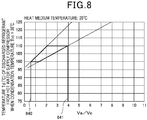
- FIG. 8 is a diagram of a relationship between the volume ratio Ve/Vc between the low pressure-side circuit internal volume Ve and the high pressure-side circuit internal volume Vc in the first refrigeration cycle 100 and the temperature of the discharged refrigerant from the hot water-supply compressor 41 when the temperature of the heating medium supplied to the hot water-supply heat exchanger 42 is 20°C.
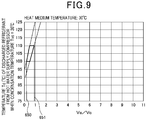
- FIG. 9 is a diagram of a relationship between the volume ratio Ve/Vc between the low pressure-side circuit internal volume Ve and the high pressure-side circuit internal volume Vc in the first refrigeration cycle 100 and the temperature of the discharged refrigerant from the hot water-supply compressor 41 when the temperature of the heating medium supplied to the hot water-supply heat exchanger 42 is 30°C.
- the outdoor gas pipe opening/closing valve 19 is set to be opened, and the outdoor suction pipe opening/closing valve 20 is set to be closed, in each of the indoor machines 30, the indoor gas pipe opening/closing valve 34 is set to be closed and the indoor suction pipe opening/closing valve 35 is set to be opened, and in the heat generation unit 40, the heat generation unit refrigerant flow adjustment valve 45 is set to be fully closed.
- the high-temperature, high-pressure air-conditioning refrigerant compressed in the air-conditioning compressor 11 enters the outdoor heat exchanger 16 via the outdoor gas pipe opening/closing valve 19 and is cooled by air around the outdoor unit 10 and turns into a liquid state.
- In the liquid-state air-conditioning refrigerant flows into the liquid pipe 27 via the outdoor refrigerant flow adjustment valve 18 in a fully-opened state and reaches the respective indoor machines 30.
- the air-conditioning refrigerant that has reached each indoor machine 30 is subjected to pressure reduction by the indoor refrigerant flow adjustment valve 33 and thereby turns into a low-temperature, low-pressure gas-liquid two-phase state, and then flows into the indoor heat exchanger 31 and takes heat from indoor air to cool the air.
- the air-conditioning refrigerant evaporates and enters the suction pipe 26 via the indoor suction pipe opening/closing valve 35 and returns to the outdoor unit 10.
- the air-conditioning refrigerant that has returned to the outdoor unit 10 returns to the air-conditioning compressor 11 via the accumulator 12.
- the outdoor gas pipe opening/closing valve 19 is set to be closed and the outdoor suction pipe opening/closing valve 20 is set to be opened
- the indoor gas pipe opening/closing valve 34 is set to be opened and the indoor suction pipe opening/closing valve 35 is set to be closed
- the heat generation unit refrigerant flow adjustment valve 45 is set to be fully closed.
- the high-temperature, high-pressure air-conditioning refrigerant compressed in the air-conditioning compressor 11 flows into the gas pipe 25 and reaches the respective indoor machines 30.
- the air-conditioning refrigerant that has reached each indoor machine 30 flows into the indoor heat exchanger 31 via the indoor gas pipe opening/closing valve 34 and releases heat to indoor air to heat the air.
- the air-conditioning refrigerant is condensed and thereby liquefied, flows into the liquid pipe 27 via the indoor refrigerant flow adjustment valve 33 in a fully-opened state and returns to the outdoor unit 10.
- the air-conditioning refrigerant that has returned to the outdoor unit 10 is subjected to pressure reduction by the outdoor refrigerant flow adjustment valve 18, turns into a low-temperature, low-pressure gas-liquid two-phase state and then enters the outdoor heat exchanger 16, and is heated by air around the outdoor unit 10 and thereby evaporates.
- the evaporated and gasified air-conditioning refrigerant returns to the air-conditioning compressor 11 via the outdoor suction pipe opening/closing valve 20 and the accumulator 12.
- the outdoor gas pipe opening/closing valve 19 is set to be closed and the outdoor suction pipe opening/closing valve 20 is set to be opened, in each of the indoor machines 30, the indoor gas pipe opening/closing valve 34 and the indoor suction pipe opening/closing valve 35 are both set to be closed, and in the heat generation unit 40, the heat generation unit refrigerant flow adjustment valve 45 is opened.
- the high-temperature, high-pressure air-conditioning refrigerant compressed in the air-conditioning compressor 11 flows into the gas pipe 25 and reaches the heat generation unit 40.
- the hot water-supply compressor 41 operates, whereby the hot water-supply refrigerant circulates through the hot water-supply compressor 41, the hot water-supply heat exchanger 42, the hot water-supply refrigerant flow adjustment valve 43 and the cascade heat exchanger 44 in this order.
- the air-conditioning refrigerant that has reached the heat generation unit 40 heats the carbon dioxide in the cascade heat exchanger 44 and the air-conditioning refrigerant itself is thereby cooled and liquefied, and then flows into the liquid pipe 27 via the heat generation unit refrigerant flow adjustment valve 45 and returns to the outdoor unit 10.
- the air-conditioning refrigerant that has returned to the outdoor unit 10 is subjected to pressure reduction by the outdoor refrigerant flow adjustment valve 18 and thereby turns into a low-temperature, low-pressure gas-liquid two-phase state, and then enters the outdoor heat exchanger 16 and is heated by air around the outdoor unit 10 and thereby evaporated.
- the evaporated and gasified air-conditioning refrigerant returns to the air-conditioning compressor 11 via the outdoor suction pipe opening/closing valve 20 and the accumulator 12.
- the carbon dioxide heated by the air-conditioning refrigerant in the cascade heat exchanger 44 is gasified and enters the hot water-supply compressor 41.
- the hot water-supply refrigerant compressed so as to have a high temperature and a high pressure by the hot water-supply compressor 41 enters the hot water-supply heat exchanger 42 and heats the heating medium up to 70 to 90°C.
- the hot water-supply refrigerant is cooled and liquefied, and is subjected to pressure reduction by the hot water-supply refrigerant flow adjustment valve 43 and then returns to the cascade heat exchanger 44 again.
- the outdoor gas pipe opening/closing valve 19 and the outdoor suction pipe opening/closing valve 20 are both set to be closed.
- the indoor gas pipe opening/closing valve 34 is set to be closed and the indoor suction pipe opening/closing valve 35 is set to be opened
- the indoor gas pipe opening/closing valve 34 is set to be opened and the indoor suction pipe opening/closing valve 35 is set to be closed.
- the heat generation unit refrigerant flow adjustment valve 45 is set to be fully closed.
- the high-temperature, high-pressure air-conditioning refrigerant compressed by the air-conditioning compressor 11 flows into the gas pipe 25 and reaches the indoor machine 30 that performs air heating.
- the air-conditioning refrigerant that has reached the indoor machine 30 that performs air heating flows into the indoor heat exchanger 31 via the indoor gas pipe opening/closing valve 34, and releases heat to indoor air to heat the air.
- the air-conditioning refrigerant is condensed and thereby liquefied and flows into the liquid pipe 27 via the fully-opened indoor refrigerant flow adjustment valve 33.
- the liquid-state air-conditioning refrigerant that has flown into the liquid pipe 27 reaches the indoor machine 30 that performs air cooling.
- the air-conditioning refrigerant that has reached the indoor machine 30 that performs air cooling is subjected to pressure reduction by the indoor refrigerant flow adjustment valve 33 and thereby turns into a low-temperature, low-pressure gas-liquid two-phase state, and then flows into the indoor heat exchanger 31 and takes heat from indoor air to cool the air.
- the air-conditioning refrigerant evaporates, enters the suction pipe 26 via the indoor suction pipe opening/closing valve 35, and returns to the outdoor unit 10.
- the air-conditioning refrigerant that has returned to the outdoor unit 10 returns to the air-conditioning compressor 11 via the accumulator 12.
- the cooling load is larger than the heating load, the liquid refrigerant supplied to the indoor machine 30 that performs air cooling from the indoor machine 30 that performs air heating is insufficient, and thus, the insufficiency is compensated by the liquid refrigerant produced in the outdoor heat exchanger 16 in the outdoor unit 10.
- the outdoor suction pipe opening/closing valve 20 kept closed, the outdoor gas pipe opening/closing valve 19 is opened, and a part of the refrigerant discharged by the air-conditioning compressor 11 is supplied to the outdoor heat exchanger 16 and is liquefied, and is supplied to the indoor machine 30 that performs air cooling, via the outdoor refrigerant flow adjustment valve 18 and the liquid pipe 27.
- the heating load is larger than the cooling load, the liquid refrigerant supplied from the indoor machine 30 that performs air heating cannot be fully evaporated in the indoor machine 30 that performs air cooling, and thus, a part of the liquid refrigerant is evaporated in the outdoor heat exchanger 16 in the outdoor unit 10.
- the outdoor suction pipe opening/closing valve 20 is opened to return the liquid refrigerant flowing out from the indoor machine 30 that performs air heating, to the outdoor unit 10 via the liquid pipe 27.
- the liquid refrigerant that has returned the outdoor unit 10 is subjected to pressure reduction by the outdoor refrigerant flow adjustment valve 18, and then evaporates in the outdoor heat exchanger 16.
- the gasified air-conditioning refrigerant returns to the accumulator 12 and the air-conditioning compressor 11 via the outdoor suction pipe opening/closing valve 20.
- the outdoor gas pipe opening/closing valve 19 and the outdoor suction pipe opening/closing valve 20 are both set to be closed.
- the indoor gas pipe opening/closing valve 34 is set to be closed and the indoor suction pipe opening/closing valve 35 is set to be opened, and in the heat generation unit 40, the heat generation unit refrigerant flow adjustment valve 45 is opened.
- the high-temperature, high-pressure air-conditioning refrigerant compressed by the air-conditioning compressor 11 flows into the gas pipe 25 and reaches the heat generation unit 40. Meanwhile, in the heat generation unit 40, the hot water-supply compressor 41 operates, whereby the hot water-supply refrigerant circulates through the hot water-supply compressor 41, the hot water-supply heat exchanger 42, the hot water-supply refrigerant flow adjustment valve 43 and the cascade heat exchanger 44 in this order.
- the air-conditioning refrigerant that has reached the heat generation unit 40 heats the carbon dioxide in the cascade heat exchanger 44 and the air-conditioning refrigerant itself is thereby cooled and liquefied, and then flows into the liquid pipe 27 via the heat generation unit refrigerant flow adjustment valve 45.
- the liquid-state air-conditioning refrigerant that has flown into the liquid pipe 27 reaches the indoor machine 30 that performs air cooling.
- the air-conditioning refrigerant that has reached the indoor machine 30 that performs air cooling is subjected to pressure reduction by the indoor refrigerant flow adjustment valve 33 and thereby turns into a low-temperature, low-pressure gas-liquid two-phase state, and then enters the indoor heat exchanger 31, and takes heat from indoor air to cool the air.
- the air-conditioning refrigerant evaporates and enters the suction pipe 26 via the indoor suction pipe opening/closing valve 35, and returns to the outdoor unit 10.
- the air-conditioning refrigerant that has returned to the outdoor unit 10 returns to the air-conditioning compressor 11 via the accumulator 12.
- the hot water-supply refrigerant heated by the air-conditioning refrigerant in the cascade heat exchanger 44 is gasified and enters the hot water-supply compressor 41.
- the hot water-supply refrigerant compressed so as to have a high temperature and a high pressure by the hot water-supply compressor 41 enters the hot water-supply heat exchanger 42 and heats the heating medium up to 70 to 90°C.
- the hot water-supply refrigerant is cooled and thereby liquefied, is subjected to pressure reduction by the hot water-supply refrigerant flow adjustment valve 43 and then returns to the cascade heat exchanger 44 again.
- the cooling load is larger than the hot water supply load, the liquid refrigerant supplied to the indoor machine 30 that performs air cooling from the heat generation unit 40 is insufficient, and thus, the insufficient is compensated by the liquid refrigerant produced in the outdoor heat exchanger 16 in the outdoor unit 10.
- the outdoor suction pipe opening/closing valve 20 kept closed, the outdoor gas pipe opening/closing valve 19 is opened, whereby a part of the refrigerant discharged by the air-conditioning compressor 11 is supplied to the outdoor heat exchanger 16 and is liquefied, and is supplied to the indoor machine 30 that performs air cooling, via the outdoor refrigerant flow adjustment valve 18 and the liquid pipe 27.
- the hot water supply load is larger than the cooling load, the liquid refrigerant supplied to the heat generation unit 40 cannot be fully evaporated in the indoor machine 30 that performs air cooling, and thus, a part of the liquid refrigerant is evaporated in the outdoor heat exchanger 16 in the outdoor unit 10.
- the outdoor gas pipe opening/closing valve 19 kept closed, the outdoor suction pipe opening/closing valve 20 is opened, and the part of the liquid refrigerant flown out from the indoor machine 30 that performs air heating is returned to the outdoor unit 10 via the liquid pipe 27.
- the liquid refrigerant that has returned to the outdoor unit 10 is subjected to pressure reduction by the outdoor refrigerant flow adjustment valve 18 and then evaporates in the outdoor heat exchanger 16.
- the gasified air-conditioning refrigerant returns to the accumulator 12 and the air-conditioning compressor 11 via the outdoor suction pipe opening/closing valve 20.
- the outdoor gas pipe opening/closing valve 19 is set to be closed and the outdoor suction pipe opening/closing valve 20 is set to be opened
- the indoor gas pipe opening/closing valve 34 is set to be opened and the indoor suction pipe opening/closing valve 35 is set to be closed
- the heat generation unit refrigerant flow adjustment valve 45 is opened.
- the high-temperature, high-pressure air-conditioning refrigerant compressed by the air-conditioning compressor 11 flows into the gas pipe 25 and reaches the respective indoor machines 30 and the heat generation unit 40.
- the air-conditioning refrigerant that has reached each indoor machine 30 flows into the indoor heat exchanger 31 via the indoor gas pipe opening/closing valve 34, and releases heat to indoor air to heat the air.
- the air-conditioning refrigerant is condensed and thereby liquefied and flows into the liquid pipe 27 via the fully-opened indoor refrigerant flow adjustment valve 33.
- the air-conditioning refrigerant that has reached the heat generation unit 40 heats the hot water-supply refrigerant in the cascade heat exchanger 44 and the air-conditioning refrigerant itself is thereby cooled and liquefied, and then flows into the liquid pipe 27 via the heat generation unit refrigerant flow adjustment valve 45.
- the liquid refrigerant merges with the liquid refrigerant that has flown out from the indoor machines 30 that perform air heating and returns to the outdoor unit 10.
- the liquid refrigerant that has returned to the outdoor unit is subjected to pressure reduction by the outdoor refrigerant flow adjustment valve 18 and then is evaporated in the outdoor heat exchanger 16.
- the gasified air-conditioning refrigerant returns to the accumulator 12 and the air-conditioning compressor 11 via the outdoor suction pipe opening/closing valve 20.
- the carbon dioxide heated by the air-conditioning refrigerant in the cascade heat exchanger 44 is gasified and enters the hot water-supply compressor 41.
- the hot water-supply refrigerant compressed so as to have a high temperature and a high pressure by the hot water-supply compressor 41 enters the hot water-supply heat exchanger 42 and heats the heating medium up to 70 to 90°C.
- the hot water-supply refrigerant is cooled and thereby liquefied, is subjected to pressure reduction by the hot water-supply refrigerant flow adjustment valve 43 and then returns to the cascade heat exchanger 44 again.
- the outdoor gas pipe opening/closing valve 19 and the outdoor suction pipe opening/closing valve 20 are both set to be closed.
- the indoor gas pipe opening/closing valve 34 is set to be closed and the indoor suction pipe opening/closing valve 35 is set to be opened
- the indoor gas pipe opening/closing valve 34 is set to be opened and the indoor suction pipe opening/closing valve 35 is set to be closed.
- the heat generation unit refrigerant flow adjustment valve 45 is opened.
- the high-temperature, high-pressure air-conditioning refrigerant compressed by the air-conditioning compressor 11 flows into the gas pipe 25 and reaches the indoor machine 30 that performs air heating and the heat generation unit 40. Meanwhile, in the heat generation unit 40, the hot water-supply compressor 41 operates, whereby the hot water-supply refrigerant circulates through the hot water-supply compressor 41, the hot water-supply heat exchanger 42, the hot water-supply refrigerant flow adjustment valve 43 and the cascade heat exchanger 44 in this order.
- the air-conditioning refrigerant that has reached the indoor machine 30 that performs air heating flows into the indoor heat exchanger 31 via the indoor gas pipe opening/closing valve 34 and releases heat to indoor air to heat the air.
- the air-conditioning refrigerant is condensed and thereby liquefied and flows into the liquid pipe 27 via the fully-opened indoor refrigerant flow adjustment valve 33.
- the air-conditioning refrigerant that has reached the heat generation unit 40 heats the carbon dioxide in the cascade heat exchanger 44 and the air-conditioning refrigerant itself is thereby cooled and liquefied and then flows into the liquid pipe 27 via the heat generation unit refrigerant flow adjustment valve 45.
- the air-conditioning refrigerant that has reached the indoor machine 30 that performs air cooling is subjected to pressure reduction by the indoor refrigerant flow adjustment valve 33 and thereby turns into a low-temperature, low-pressure gas-liquid two-phase state, and then flows into the indoor heat exchanger 31 and takes heat from indoor air to cool the air.
- the air-conditioning refrigerant evaporates, and enters the suction pipe 26 via the indoor suction pipe opening/closing valve 35 and returns to the outdoor unit 10.
- the air-conditioning refrigerant that has returned to the outdoor unit 10 returns to the air-conditioning compressor 11 via the accumulator 12.
- the carbon dioxide heated by the air-conditioning refrigerant in the cascade heat exchanger 44 is gasified and enters the hot water-supply compressor 41.
- the hot water-supply refrigerant compressed so as to have a high temperature and a high pressure by the hot water-supply compressor 41 enters the hot water-supply heat exchanger 42 and heats the heating medium up to 70 to 90°C.
- the hot water-supply refrigerant is cooled and thereby liquefied, and is subjected to pressure reduction by the hot water-supply refrigerant flow adjustment valve 43 and then returns to the cascade heat exchanger 44 again.
- the cooling load is larger than the sum of the heating load and hot water supply load, the liquid refrigerant supplied to the indoor machine 30 from the indoor machine 30 that performs air heating and the heat generation unit 40 is insufficient, and thus, the insufficiency is compensated by the liquid refrigerant produced in the outdoor heat exchanger 16 in the outdoor unit 10.
- the outdoor suction pipe opening/closing valve 20 kept closed, the outdoor gas pipe opening/closing valve 19 is opened, and a part of the refrigerant discharged by the air-conditioning compressor 11 is supplied to the outdoor heat exchanger 16 and is liquefied, and is supplied to the indoor machine 30 that performs air cooling via the outdoor refrigerant flow adjustment valve 18 and the liquid pipe 27.
- the liquid refrigerant supplied from the indoor machine 30 that performs air heating and the heat generation unit 40 cannot be fully evaporated in the indoor machine 30 that performs air cooling, and thus, a part of the liquid refrigerant is evaporated in the outdoor heat exchanger 16 in the outdoor unit 10.
- the outdoor gas pipe opening/closing valve 19 kept closed, the outdoor suction pipe opening/closing valve 20 is opened, and the part of the liquid refrigerant flown out from the indoor machine 30 that performs air heating and the heat generation unit 40 returns to the outdoor unit 10 via the liquid pipe 27.
- the liquid refrigerant that has returned to the outdoor unit 10 is subjected to pressure reduction by the outdoor refrigerant flow adjustment valve 18 and then evaporates in the outdoor heat exchanger 16.
- the gasified air-conditioning refrigerant returns to the accumulator 12 and the air-conditioning compressor 11 via the outdoor suction pipe opening/closing valve 20.
- the hot water-supply compressor 41 and the heating medium pump 46 operate.
- the heating medium pump 46 the heating medium flows into the heat generation unit 40 from the outside of the heat generation unit 40 such as a water supply, and enters the heating medium pump 46 through the heating medium piping 63.
- the heating medium that has flown into the heating medium pump 46 flows into the heating medium piping 64 from a discharge port and enters the hot water-supply heat exchanger 42.
- the heating medium exchanges heat with the high-temperature carbon dioxide discharged by the hot water-supply compressor 41 in the hot water-supply heat exchanger 42, which is a double pipe-type heat exchanger, and is thereby heated up to 70 to 90°C, and then sent to the outside of the heat generation unit 40 through the heating medium piping 65.
- heating medium piping 63 heating medium pump 46 ⁇ heating medium piping 64 ⁇ hot water-supply heat exchanger 42 ⁇ heating medium piping 65
- resin materials and copper there are both resin materials and copper and thus there are parts of connection between different materials.
- the hot water-supply heat exchanger 42 is installed so as to be not in contact with the bottom plate member 51 to which the hot water-supply compressor 41 fixes and be fixed to the side plate member 52, and thus, vibration during operation of the hot water-supply compressor 41 is not transmitted directly to the hot water-supply heat exchanger 42 through the bottom plate member 51.
- the discharge temperature Td in the hot water-supply compressor 41 in the first refrigeration cycle 100 falls within a range of 100 to 110°C, which is equal to or below the use upper limit discharge temperature for the hot water-supply compressor 41.
- the present invention can favorably be used as one providing a highly-reliable refrigeration cycle in which carbon dioxide that does not impair a durability of a hot water-supply compressor 41 circulates, in an air-conditioning/hot water-supply system that can simultaneously supply hot and cold heat necessary for air cooling, air heating and hot water supply.
Landscapes
- Engineering & Computer Science (AREA)
- Mechanical Engineering (AREA)
- General Engineering & Computer Science (AREA)
- Physics & Mathematics (AREA)
- Thermal Sciences (AREA)
- Chemical & Material Sciences (AREA)
- Combustion & Propulsion (AREA)
- Life Sciences & Earth Sciences (AREA)
- Sustainable Development (AREA)
- Heat-Pump Type And Storage Water Heaters (AREA)
Applications Claiming Priority (1)
| Application Number | Priority Date | Filing Date | Title |
|---|---|---|---|
| JP2016044074A JP2017161115A (ja) | 2016-03-08 | 2016-03-08 | 空調給湯システム |
Publications (1)
| Publication Number | Publication Date |
|---|---|
| EP3217123A1 true EP3217123A1 (de) | 2017-09-13 |
Family
ID=58158949
Family Applications (1)
| Application Number | Title | Priority Date | Filing Date |
|---|---|---|---|
| EP17157736.4A Withdrawn EP3217123A1 (de) | 2016-03-08 | 2017-02-23 | Klimatisierungs-/heisswasserversorgungssystem |
Country Status (3)
| Country | Link |
|---|---|
| EP (1) | EP3217123A1 (de) |
| JP (1) | JP2017161115A (de) |
| CN (1) | CN107166580A (de) |
Cited By (2)
| Publication number | Priority date | Publication date | Assignee | Title |
|---|---|---|---|---|
| CN114502887A (zh) * | 2019-09-30 | 2022-05-13 | 大金工业株式会社 | 冷冻装置 |
| EP4177546A1 (de) * | 2021-11-08 | 2023-05-10 | Ariston S.P.A. | Mit stossschutzmitteln ausgestattete gehäusekammer für den kältemittelkreislauf einer wärmepumpe |
Families Citing this family (4)
| Publication number | Priority date | Publication date | Assignee | Title |
|---|---|---|---|---|
| JP7024537B2 (ja) * | 2018-03-22 | 2022-02-24 | 株式会社デンソー | 冷却装置 |
| CN109579300A (zh) * | 2018-12-21 | 2019-04-05 | 广东志高暖通设备股份有限公司 | 一种具有多四通阀流路切换的热水多联系统及控制方法 |
| CN109579299A (zh) * | 2018-12-21 | 2019-04-05 | 广东志高暖通设备股份有限公司 | 一种热水多联系统及其控制方法 |
| CN111337280B (zh) * | 2020-02-29 | 2021-09-03 | 同济大学 | 一种用于vrf空调系统变工况下的冷热量测试系统及方法 |
Citations (6)
| Publication number | Priority date | Publication date | Assignee | Title |
|---|---|---|---|---|
| JP2004132647A (ja) | 2002-10-11 | 2004-04-30 | Daikin Ind Ltd | 給湯装置、空調給湯システム、及び給湯システム |
| US20050178151A1 (en) * | 2004-02-12 | 2005-08-18 | Sanyo Electric Co., Ltd. | Refrigerant cycle apparatus |
| JP2005226927A (ja) * | 2004-02-13 | 2005-08-25 | Sanyo Electric Co Ltd | 冷媒サイクル装置 |
| US20100300135A1 (en) * | 2009-05-27 | 2010-12-02 | Masahisa Otake | Refrigerating apparatus |
| US20110314848A1 (en) * | 2009-03-31 | 2011-12-29 | Mitsubishi Electric Corporation | Combined air-conditioning and hot-water supply system |
| DE102014214656A1 (de) * | 2014-07-25 | 2016-01-28 | Konvekta Ag | Kompressionskälteanlage und Verfahren zum Betrieb einer Kompressionskälteanlage |
Family Cites Families (3)
| Publication number | Priority date | Publication date | Assignee | Title |
|---|---|---|---|---|
| CN2586921Y (zh) * | 2002-06-29 | 2003-11-19 | 海尔集团公司 | 定频多联空调系统的冷媒控制器 |
| EP2184563A4 (de) * | 2008-02-04 | 2016-02-17 | Mitsubishi Electric Corp | Klimaanlagen- und wasserheizungskomplexsystem |
| CN102384538B (zh) * | 2011-07-05 | 2013-10-09 | 广东美的暖通设备限公司 | 三管制热回收多联机及其控制方法 |
-
2016
- 2016-03-08 JP JP2016044074A patent/JP2017161115A/ja active Pending
- 2016-08-29 CN CN201610752080.5A patent/CN107166580A/zh active Pending
-
2017
- 2017-02-23 EP EP17157736.4A patent/EP3217123A1/de not_active Withdrawn
Patent Citations (7)
| Publication number | Priority date | Publication date | Assignee | Title |
|---|---|---|---|---|
| JP2004132647A (ja) | 2002-10-11 | 2004-04-30 | Daikin Ind Ltd | 給湯装置、空調給湯システム、及び給湯システム |
| JP3925383B2 (ja) | 2002-10-11 | 2007-06-06 | ダイキン工業株式会社 | 給湯装置、空調給湯システム、及び給湯システム |
| US20050178151A1 (en) * | 2004-02-12 | 2005-08-18 | Sanyo Electric Co., Ltd. | Refrigerant cycle apparatus |
| JP2005226927A (ja) * | 2004-02-13 | 2005-08-25 | Sanyo Electric Co Ltd | 冷媒サイクル装置 |
| US20110314848A1 (en) * | 2009-03-31 | 2011-12-29 | Mitsubishi Electric Corporation | Combined air-conditioning and hot-water supply system |
| US20100300135A1 (en) * | 2009-05-27 | 2010-12-02 | Masahisa Otake | Refrigerating apparatus |
| DE102014214656A1 (de) * | 2014-07-25 | 2016-01-28 | Konvekta Ag | Kompressionskälteanlage und Verfahren zum Betrieb einer Kompressionskälteanlage |
Cited By (3)
| Publication number | Priority date | Publication date | Assignee | Title |
|---|---|---|---|---|
| CN114502887A (zh) * | 2019-09-30 | 2022-05-13 | 大金工业株式会社 | 冷冻装置 |
| CN114502887B (zh) * | 2019-09-30 | 2023-08-08 | 大金工业株式会社 | 冷冻装置 |
| EP4177546A1 (de) * | 2021-11-08 | 2023-05-10 | Ariston S.P.A. | Mit stossschutzmitteln ausgestattete gehäusekammer für den kältemittelkreislauf einer wärmepumpe |
Also Published As
| Publication number | Publication date |
|---|---|
| JP2017161115A (ja) | 2017-09-14 |
| CN107166580A (zh) | 2017-09-15 |
Similar Documents
| Publication | Publication Date | Title |
|---|---|---|
| EP3217123A1 (de) | Klimatisierungs-/heisswasserversorgungssystem | |
| CN103328909B (zh) | 空气调节装置 | |
| JP5318099B2 (ja) | 冷凍サイクル装置、並びにその制御方法 | |
| JP4670329B2 (ja) | 冷凍空調装置、冷凍空調装置の運転制御方法、冷凍空調装置の冷媒量制御方法 | |
| CN106030219B (zh) | 空气调节装置 | |
| CN102425872A (zh) | 冷冻循环装置 | |
| JPWO2012160597A1 (ja) | 空気調和装置 | |
| JP7122507B2 (ja) | 冷凍サイクル装置 | |
| JP2013053758A (ja) | 超臨界サイクルおよびそれを用いたヒートポンプ給湯機 | |
| EP3109566B1 (de) | Klimaanlagenvorrichtung | |
| US12104818B2 (en) | Air-conditioning apparatus | |
| JPWO2020188756A1 (ja) | ルームエアコン | |
| CN108431526A (zh) | 空调装置 | |
| JP6643627B2 (ja) | 熱生成ユニット | |
| EP3217117A1 (de) | Klimatisierungs-/heisswasserversorgungssystem | |
| JP2016166714A (ja) | 熱生成ユニット | |
| WO2022029845A1 (ja) | 空気調和装置 | |
| EP3404341A1 (de) | Kältekreislaufvorrichtung und flüssigkeitsumwälzvorrichtung damit | |
| JP6544517B2 (ja) | 熱生成ユニット | |
| EP3835687A1 (de) | Wärmepumpe | |
| JPWO2016185689A1 (ja) | 空調給湯システム | |
| JP2017172898A (ja) | 空調給湯システム |
Legal Events
| Date | Code | Title | Description |
|---|---|---|---|
| PUAI | Public reference made under article 153(3) epc to a published international application that has entered the european phase |
Free format text: ORIGINAL CODE: 0009012 |
|
| AK | Designated contracting states |
Kind code of ref document: A1 Designated state(s): AL AT BE BG CH CY CZ DE DK EE ES FI FR GB GR HR HU IE IS IT LI LT LU LV MC MK MT NL NO PL PT RO RS SE SI SK SM TR |
|
| AX | Request for extension of the european patent |
Extension state: BA ME |
|
| 17P | Request for examination filed |
Effective date: 20180313 |
|
| RBV | Designated contracting states (corrected) |
Designated state(s): AL AT BE BG CH CY CZ DE DK EE ES FI FR GB GR HR HU IE IS IT LI LT LU LV MC MK MT NL NO PL PT RO RS SE SI SK SM TR |
|
| STAA | Information on the status of an ep patent application or granted ep patent |
Free format text: STATUS: THE APPLICATION HAS BEEN WITHDRAWN |
|
| 18W | Application withdrawn |
Effective date: 20191212 |