EP3218675B1 - Procédé et dispositif de détection, d'évaluation et d'affichage de valeurs de mesure de moteurs d'entraînements électriques - Google Patents
Procédé et dispositif de détection, d'évaluation et d'affichage de valeurs de mesure de moteurs d'entraînements électriques Download PDFInfo
- Publication number
- EP3218675B1 EP3218675B1 EP15788407.3A EP15788407A EP3218675B1 EP 3218675 B1 EP3218675 B1 EP 3218675B1 EP 15788407 A EP15788407 A EP 15788407A EP 3218675 B1 EP3218675 B1 EP 3218675B1
- Authority
- EP
- European Patent Office
- Prior art keywords
- data
- measurement values
- values
- time
- colour
- Prior art date
- Legal status (The legal status is an assumption and is not a legal conclusion. Google has not performed a legal analysis and makes no representation as to the accuracy of the status listed.)
- Active
Links
Images

Classifications
-
- G—PHYSICS
- G01—MEASURING; TESTING
- G01D—MEASURING NOT SPECIALLY ADAPTED FOR A SPECIFIC VARIABLE; ARRANGEMENTS FOR MEASURING TWO OR MORE VARIABLES NOT COVERED IN A SINGLE OTHER SUBCLASS; TARIFF METERING APPARATUS; MEASURING OR TESTING NOT OTHERWISE PROVIDED FOR
- G01D7/00—Indicating measured values
- G01D7/02—Indicating value of two or more variables simultaneously
- G01D7/08—Indicating value of two or more variables simultaneously using a common indicating element for two or more variables
- G01D7/10—Indicating value of two or more variables simultaneously using a common indicating element for two or more variables giving indication in co-ordinate form
-
- G—PHYSICS
- G07—CHECKING-DEVICES
- G07C—TIME OR ATTENDANCE REGISTERS; REGISTERING OR INDICATING THE WORKING OF MACHINES; GENERATING RANDOM NUMBERS; VOTING OR LOTTERY APPARATUS; ARRANGEMENTS, SYSTEMS OR APPARATUS FOR CHECKING NOT PROVIDED FOR ELSEWHERE
- G07C3/00—Registering or indicating the condition or the working of machines or other apparatus, other than vehicles
Definitions
- the invention relates to a method for detecting, evaluating and displaying measured values of motors of electric drives and to a device for implementing the method.
- Umstellvor bland between mechanical states using electric motors are realized. Frequently, the switching processes are cyclical in the sense that always between at least two defined states and is made. Examples of such electrically driven systems are barriers for level crossings, drives for changing over the points position in rail-bound traffic or drives for opening and closing windows, gates, etc.
- the positioning motors run in a reproducible manner from defined initial to defined end points and back again. If the functionality and the technical condition of such systems are to be monitored, it is necessary, among other things, to make a statement about the sluggishness of the system. For this purpose, for example, the electrical characteristic curves of the drive motors are determined and evaluated.
- an evaluation of the measured value data is required. For point drives, for example, the current profile during a changeover process is recorded and compared with a reference curve. The data is displayed on an output device which has an ordinary coordinate system in which the abscissa is the measuring time and the ordinate is the current intensity or the difference between the measured current values and the reference curve. In such a representation, however, a comparison with earlier or later measurements is difficult to make clear.
- the DE 197 33 001 A1 describes a method for the acquisition, evaluation and display of measured values, in which the measured or comparison values are displayed in alphanumeric Form are shown, wherein the alphanumeric representation of a measurement or comparison value is assigned in each case a color value in the representation, which is selected in each case depending on the determined comparison value.
- the document DE 32 37 407 A1 shows a method and device for acquiring, evaluating and displaying measured values of motors, in which a speed sensor measures measured values and transmits them to a computer, which processes them and displays the measurement results on a display as a family of curves that codes in color can be.
- Object of the present invention is to provide a method by which the technical condition of electric motors motors can not only be assessed at a given time, but also the temporal evolution of the state is detected and illustrated, so also statements about an expected maintenance can be made and conclusions about the causes of state changes can be drawn. Furthermore, a device is to be provided, which implements the method.
- the method according to the invention as claimed in claim 1 represents a measuring method in which the measured values of motors of electric drives are recorded, evaluated and displayed.
- the electrical characteristic values of the motor measured by at least one sensor can be used as measured values.
- frame parameters such as temperature, humidity, etc. can also be measured and included in the evaluation.
- the measured values are transmitted to a data processing system where they are stored and evaluated.
- an evaluation function can compare the measured values with reference values under the given conditions and use only the differences between the measured values and the reference values as further data to be considered.
- the measured values can be compared with one another over a period of time that is dependent on the mechanical position of the driven components. If, for example, the startup behavior of the Engine changes due to a wear-related mechanical stiffness, the power consumption of the drive will gradually increase over time. In order to be able to recognize such a trend at an early stage, the data from a longer period must be compared with each other.
- a multidimensional representation is only clear when the information is edited. This is done according to the invention by considering two time coordinates.
- the measured values within one revolution cycle of the drive are described as a function of the one time coordinate, which is referred to as the circulation time T U.
- both coordinate axes are selected perpendicular to one another. In the x direction, for example, T V can be represented, while the y direction is characterized by T U.
- the zi values are color-coded.
- the sequence of colored data points in the y direction indicates the difference between the data value and the reference value within a circulation time T U , which was measured during one revolution at time T Vi .
- T U circulation time
- the amount of information is reduced in that not every single z-value, but only certain value classes are coded, which are based on defined tolerance values for the data.
- the data points along a parallels to the comparison time axis are then analyzed to determine whether a change in the data points takes place in the direction of a tolerance limit to be defined. If a data value gradually exceeds ever higher tolerance thresholds during a certain phase of the drive, it is to be expected that a critical state of the drive follows, so that here too a message appears at the output unit indicating that the system is being serviced by the service personnel must be examined.
- Claims 4 to 6 relate to a device for implementing the method of the previous claims.
- a device which records, stores, evaluates and displays the measured values of motors of electric drives.
- the device consists of at least one measuring sensor, which is connected to a data processing system which has an output unit for displaying the evaluation results and means for data input.
- the evaluation of the measured data takes place with the help of the data processing system.
- the electrical characteristic values of the motor measured by at least one sensor can be used as measured values.
- the device also measure frame parameters such as temperature, humidity, etc. and include them in the evaluation. For the evaluation of the data, it may be advantageous if the device processes the measured values appropriately.
- the device can compare the measured values with reference values under the given boundary conditions and use only the differences between the measured values and the reference values as further data to be considered.
- the device according to the invention considers two time coordinates. It describes the measured values within a circulation cycle of the drive as a function of the orbital period T U.
- the representation of the data takes place in a two-dimensional coordinate system with two mutually perpendicular coordinate axes, with T V as the abscissa (x-axis) and T U as the ordinate (y-axis).
- the device displays on its output unit the values of the data belonging to each (yi; zi) pair in the coordinate system by projecting the measured values onto the T U axis and thereby the measured values given by the zi values. color coded.
- the sequence of colored data points in the y direction indicates the difference between the data value and the reference value within a circulation time T U , which was measured during one revolution at time T Vi .
- the device displays on its output unit the data values at T V (i + 1) in the same way. Since the (y (i + 1); z (i + 1)) value pairs For the (yi; zi) value pairs in the direction of the T V axis are parallel shifted, the two juxtaposed measurements can be easily compared with each other for evaluation.
- the device reduces the amount of information in that it does not encode each individual measured value in the measuring area with its own color, but only certain value classes, which are based on defined tolerance values for the data.
- the device assigns only a few colors correspondingly to the z values. Based on Color of the data point is thus recognizable which tolerance limit of the data point (y; z) is exceeded.
- the device advantageously indicates an investigation requirement of the drive. This occurs, for example, when a data point has reached a tolerance limit to be defined, which is known as proof of damage or a threat to the drive, at least once.
- the device analyzes the data points along a parallel to the comparison time axis to determine whether a change of the data points takes place in the direction of a tolerance limit to be defined. If a data value gradually exceeds ever higher tolerance thresholds during a certain phase of the drive's revolution, the device at the output unit issues a message indicating that the system must be inspected by service personnel.
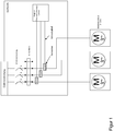
- Fig. 1 shows an example of the analysis of points in the rail network of a track-bound transport system.
- magnetic field sensors that are designed, for example, as 3D or multidimensional magnetic field sensors
- the measured magnetic fields from a data processing system determine the current strength and the direction of rotation of the point machine.
- the current waveform is used in the analysis of the data as a measure of the stiffness of the switch.
- each 4-wire turnout drive cable is assigned a single stroke;
- the diagnostic device measures directly on the existing cabling of the respective point machine drive, near a terminal block. Ideally, the terminal strip between the outer cable and the inner cable is used for this purpose.
- the transmission of the measured data takes place by means of a suitable interface.
- a suitable interface In this example a 4-20 mA interface is used.
- wired interfaces are possible, as well as wireless, eg wireless interfaces.
- the control of the measurement process, the preparation of the measurement data and the forwarding to a diagnostic system are functions of the connected data processing.
- Fig. 2 shows an exemplary representation of the measured data for the evaluation of the data of the points drive.
- the measured current values are subtracted from the reference values of an intact drive stored in a database.
- the differences from the reference values, ⁇ I are divided into tolerance ranges. No or only slight deviations from the reference value are assigned to the tolerance range T0 in this example. Larger deviations in the tolerance ranges T1 to T4. When the tolerance range T4 is reached, there is an acute danger to the functionality of the drive. Negative deviations indicate better drive stiffness compared to the reference values.
- These measured values are assigned to the tolerance range T-1. Each tolerance range is now assigned its own color when displaying the measured values.
- the color green is assigned to the tolerance range T0 in this example and thus stands for a correspondence of the measured data with the reference values or an insignificant deviation.
- T1 to T4 are assigned, for example, the colors yellow, orange, bright red and dark red, T-1 the color blue.
- the comparison time T V is plotted in the x direction, and the y direction shows the measured values during one revolution (T U ) of the drive.
- T U The comparison time
- a prediction of the expected temporal course of damage is displayed by comparison with data stored in the database. Based on this forecast, the optimal maintenance time can be determined.
- the optimal maintenance time can be determined in the upper area of the FIG. 2 (Left-hand rotation) is an example of how a sudden transition from green color values to red occurs.
- an event has caused a damage to the switch, which must be rectified immediately. Accordingly, an alarm message is issued and an immediate check of the system is triggered.
- the spare parts needed for the repair are determined and displayed by comparison with the data stored in a database.
Landscapes
- Physics & Mathematics (AREA)
- General Physics & Mathematics (AREA)
- Testing And Monitoring For Control Systems (AREA)
- Testing Or Calibration Of Command Recording Devices (AREA)
- Electric Propulsion And Braking For Vehicles (AREA)
- Testing Of Devices, Machine Parts, Or Other Structures Thereof (AREA)
Claims (6)
- Procédé de détection, d'évaluation et d'affichage de valeurs de mesure de moteurs d'entraînements électriques, dans lequel on mesure par au moins un capteur des valeurs de mesure qui sont transférées à un équipement de traitement de données, caractérisé en ce que deux coordonnées de temps sont prises en compte, dans lequel les valeurs de mesure à l'intérieur d'un cycle de rotation de l'entraînement sont décrites en fonction de la première coordonnée de temps qui est dénommée temps de rotation et les rotations successives de l'entraînement sont décrites en fonction de la seconde coordonnée de temps, qui est dénommée temps de comparaison, dans lequel les valeurs de mesure d'un cycle de rotation de l'entraînement électrique sont mémorisées et éventuellement traitées avec une fonction d'évaluation, et ces données sont comparées ensuite à une courbe de référence, dans lequel les divergences entre les données et la courbe de référence sont codées en couleur et sont affichées sur une unité de sortie de sorte que les deux coordonnées de temps soient représentées perpendiculairement l'une à l'autre et que les points de données codés en couleur soient respectivement affichés dans une position de la surface d'affichage bidimensionnelle qui correspond aux coordonnées associées le long de l'axe de temps de rotation et de l'axe de temps de comparaison de sorte que l'on obtienne, au cours de plusieurs cycles de mesure, une succession des points de données codés en couleur.
- Procédé de détection, d'évaluation et d'affichage de valeurs de mesure de moteurs d'entraînements électriques selon la revendication 1, dans lequel le codage des valeurs de couleurs pour les divergences des données vis-à-vis des valeurs de référence est choisi en fonction de plages de tolérance de sorte que l'on puisse reconnaître sur base de la couleur du point de données à la sortie des données les limites de tolérance qui sont dépassées par les valeurs de mesure au point de données respectif.
- Procédé de détection, d'évaluation et d'affichage de valeurs de mesure de moteurs d'entraînements électriques selon l'une quelconque des revendications précédentes 1 à 2, dans lequel, lors d'un besoin d'analyse de l'entraînement, on indique si un point de données a atteint au moins une fois une limite de tolérance à définir ou si la comparaison des points de données le long d'une parallèle à l'axe de temps de comparaison fournit une modification des points de données dans la direction d'une limite de tolérance à définir.
- Dispositif de détection, d'évaluation et d'affichage de valeurs de mesure de moteurs d'entraînements électriques, dans lequel au moins un capteur mesure des valeurs de mesure et les transfère à un équipement de traitement de données, caractérisé en ce que l'équipement de traitement de données est réglé de manière à utiliser pour l'évaluation des coordonnées de temps, dans lequel les valeurs de mesure à l'intérieur d'un cycle de rotation de l'entraînement sont décrites par la première coordonnée de temps, qui est dénommée temps de rotation, et les rotations successives de l'entraînement sont décrites en fonction de la seconde coordonnée de temps, qui est dénommée temps de comparaison, dans lequel il mémorise les valeurs de mesure d'un cycle de rotation de l'entraînement électrique et les traite éventuellement avec une fonction d'évaluation et compare ensuite ces données à une courbe de référence, dans lequel les divergences entre les données et la courbe de référence sont codées en couleur et sont affichées sur une unité de sortie de sorte qu'il représente les deux coordonnées de temps perpendiculairement l'une à l'autre et affiche les points de données codés en couleurs respectivement dans une position de la surface d'affichage bidimensionnelle qui correspond aux coordonnées associées le long de l'axe de temps de rotation et de l'axe de temps de comparaison de sorte que l'on obtienne, au cours de plusieurs cycles de mesure, une succession des points de données codés en couleurs.
- Dispositif de détection, d'évaluation et d'affichage de valeurs de mesure de moteurs d'entraînements électriques selon la revendication 4, dans lequel l'équipement de traitement de données est réglé de manière à choisir le codage des valeurs de couleur pour les divergences des données vis-à-vis des valeurs de référence en fonction de plages de tolérances de sorte qu'à la lumière de la couleur du point de données sur l'unité de sortie, on puisse reconnaître les limites de tolérance qui dépassent les valeurs de mesure au point de données respectif.
- Dispositif de détection, d'évaluation et d'affichage de valeurs de mesure de moteurs d'entraînement électriques selon l'une quelconque des revendications 4 à 5, dans lequel l'équipement de traitement de données est réglé de manière à indiquer au moyen d'un message lors d'un besoin d'analyse de l'entraînement si un point de données a atteint au moins une fois une limite de tolérance à définir ou si la comparaison des points de données le long d'une parallèle à l'axe de temps de comparaison indique une modification des points de données dans la direction d'une limite de tolérance à définir.
Priority Applications (2)
| Application Number | Priority Date | Filing Date | Title |
|---|---|---|---|
| PL15788407T PL3218675T3 (pl) | 2014-11-14 | 2015-11-02 | Sposób rejestrowania, analizowania i prezentowania wartości pomiarowych silników napędów elektrycznych |
| SI201530644T SI3218675T1 (sl) | 2014-11-14 | 2015-11-02 | Postopek in naprava za zaznavanje, ocenjevanje in predstavitev izmerjenih vrednosti motorjev električnih pogonov |
Applications Claiming Priority (2)
| Application Number | Priority Date | Filing Date | Title |
|---|---|---|---|
| DE102014223251.1A DE102014223251B3 (de) | 2014-11-14 | 2014-11-14 | Verfahren und Vorrichtung zur Erfassung, Auswertung und Darstellung von Messwerten von Motoren elektrischer Antriebe |
| PCT/EP2015/075443 WO2016074967A1 (fr) | 2014-11-14 | 2015-11-02 | Procédé et dispositif de détection, d'évaluation et de présentation de valeurs de mesure de moteurs d'entraînements electriques |
Publications (2)
| Publication Number | Publication Date |
|---|---|
| EP3218675A1 EP3218675A1 (fr) | 2017-09-20 |
| EP3218675B1 true EP3218675B1 (fr) | 2019-01-09 |
Family
ID=54366226
Family Applications (1)
| Application Number | Title | Priority Date | Filing Date |
|---|---|---|---|
| EP15788407.3A Active EP3218675B1 (fr) | 2014-11-14 | 2015-11-02 | Procédé et dispositif de détection, d'évaluation et d'affichage de valeurs de mesure de moteurs d'entraînements électriques |
Country Status (14)
| Country | Link |
|---|---|
| EP (1) | EP3218675B1 (fr) |
| KR (1) | KR20170092572A (fr) |
| CN (1) | CN107110671B (fr) |
| AU (1) | AU2015345343A1 (fr) |
| CA (1) | CA2970403C (fr) |
| DE (1) | DE102014223251B3 (fr) |
| EA (1) | EA032103B1 (fr) |
| ES (1) | ES2717121T3 (fr) |
| LT (1) | LT3218675T (fr) |
| PL (1) | PL3218675T3 (fr) |
| PT (1) | PT3218675T (fr) |
| SG (1) | SG11201704698UA (fr) |
| SI (1) | SI3218675T1 (fr) |
| WO (1) | WO2016074967A1 (fr) |
Families Citing this family (4)
| Publication number | Priority date | Publication date | Assignee | Title |
|---|---|---|---|---|
| DE102018211846A1 (de) * | 2018-07-17 | 2020-01-23 | Ziehl-Abegg Se | Verfahren und System zum Bewerten eines Schwingungsverhaltens eines Elektromotors |
| DE102018220804A1 (de) * | 2018-12-03 | 2020-06-04 | Lufthansa Technik Aktiengesellschaft | Zustandsüberwachungsverfahren und -vorrichtung |
| KR102112871B1 (ko) * | 2019-07-01 | 2020-06-04 | 서준식 | 모터 평가 시스템 |
| CN117271863A (zh) * | 2023-09-21 | 2023-12-22 | 广东电网有限责任公司广州供电局 | 开关机械特性试验数据智能分析处理方法 |
Family Cites Families (13)
| Publication number | Priority date | Publication date | Assignee | Title |
|---|---|---|---|---|
| DE1506630B2 (de) * | 1967-04-15 | 1972-01-27 | Dormer AG, 7990 Friedrichshafen | Fluginstrumentierung mit elektronischer. anzeige |
| JPS5862515A (ja) * | 1981-10-09 | 1983-04-14 | Honda Motor Co Ltd | 車両の表示装置 |
| NO843698L (no) * | 1984-09-17 | 1986-03-18 | Norway Geophysical Co | Fremgangsm¨te til behandling av seismiske data. |
| JPH06103310B2 (ja) * | 1985-06-26 | 1994-12-14 | 株式会社日立製作所 | 自動分析装置の精度管理データの表示方法 |
| KR100485025B1 (ko) * | 1994-10-26 | 2005-06-16 | 지멘스 악티엔게젤샤프트 | 측정값분석방법및그방법을실시하기위한측정값분석기 |
| DE19733001A1 (de) * | 1997-07-31 | 1999-02-04 | Volkswagen Ag | Verfahren zur Erfassung, Auswertung und Darstellung von Meßwerten |
| KR20090030902A (ko) * | 2007-09-21 | 2009-03-25 | 엘지전자 주식회사 | 식기세척기의 입력장치 및 그 제어방법, 세탁장치의입력장치 및 그 제어방법 |
| JP5243910B2 (ja) * | 2008-09-29 | 2013-07-24 | 本田技研工業株式会社 | 燃費向上のための運転操作を運転者に指導するための装置 |
| KR101713351B1 (ko) * | 2009-04-27 | 2017-03-07 | 스미스 앤드 네퓨, 인크. | 랜드마크를 식별하는 시스템 및 방법 |
| DE102009023867A1 (de) * | 2009-06-04 | 2010-12-09 | Bayerische Motoren Werke Aktiengesellschaft | Verfahren zur Fahrerinformation in einem Fahrzeug, insbesondere in einem Kraftfahrzeug |
| DE102009035998A1 (de) * | 2009-07-27 | 2011-02-03 | Pilz Gmbh & Co. Kg | Verfahren und Vorrichtung zum fehlersicheren Überwachen einer Bewegungsgröße an einem elektrischen Antrieb |
| PL2309282T3 (pl) * | 2009-08-11 | 2021-07-05 | Diehl Ako Stiftung & Co. Kg | Sposób wykrywania błędów przy sterowaniu silnikiem pola wirującego |
| DE102010055797A1 (de) * | 2010-12-23 | 2012-06-28 | Continental Automotive Gmbh | Elektrokraftfahrzeug mit einer Anzeigevorrichtung |
-
2014
- 2014-11-14 DE DE102014223251.1A patent/DE102014223251B3/de not_active Expired - Fee Related
-
2015
- 2015-11-02 ES ES15788407T patent/ES2717121T3/es active Active
- 2015-11-02 PL PL15788407T patent/PL3218675T3/pl unknown
- 2015-11-02 SG SG11201704698UA patent/SG11201704698UA/en unknown
- 2015-11-02 CA CA2970403A patent/CA2970403C/fr active Active
- 2015-11-02 KR KR1020177015627A patent/KR20170092572A/ko not_active Withdrawn
- 2015-11-02 SI SI201530644T patent/SI3218675T1/sl unknown
- 2015-11-02 AU AU2015345343A patent/AU2015345343A1/en not_active Abandoned
- 2015-11-02 PT PT15788407T patent/PT3218675T/pt unknown
- 2015-11-02 WO PCT/EP2015/075443 patent/WO2016074967A1/fr not_active Ceased
- 2015-11-02 CN CN201580067132.9A patent/CN107110671B/zh not_active Expired - Fee Related
- 2015-11-02 LT LTEP15788407.3T patent/LT3218675T/lt unknown
- 2015-11-02 EA EA201791022A patent/EA032103B1/ru not_active IP Right Cessation
- 2015-11-02 EP EP15788407.3A patent/EP3218675B1/fr active Active
Non-Patent Citations (1)
| Title |
|---|
| None * |
Also Published As
| Publication number | Publication date |
|---|---|
| EA201791022A1 (ru) | 2017-09-29 |
| ES2717121T3 (es) | 2019-06-19 |
| PT3218675T (pt) | 2019-04-03 |
| WO2016074967A1 (fr) | 2016-05-19 |
| DE102014223251B3 (de) | 2016-03-24 |
| AU2015345343A1 (en) | 2017-06-29 |
| CN107110671B (zh) | 2019-05-07 |
| CA2970403A1 (fr) | 2016-05-19 |
| EP3218675A1 (fr) | 2017-09-20 |
| LT3218675T (lt) | 2019-04-10 |
| SG11201704698UA (en) | 2017-07-28 |
| KR20170092572A (ko) | 2017-08-11 |
| SI3218675T1 (sl) | 2019-05-31 |
| CA2970403C (fr) | 2023-12-19 |
| EA032103B1 (ru) | 2019-04-30 |
| PL3218675T3 (pl) | 2019-06-28 |
| CN107110671A (zh) | 2017-08-29 |
Similar Documents
| Publication | Publication Date | Title |
|---|---|---|
| DE102014223234B3 (de) | Verfahren und Vorrichtung zur Diagnose elektrischer Weichen | |
| EP2877383B1 (fr) | Procédé de diagnostic pour véhicules ferroviaires | |
| EP3218675B1 (fr) | Procédé et dispositif de détection, d'évaluation et d'affichage de valeurs de mesure de moteurs d'entraînements électriques | |
| EP2047118B1 (fr) | Procédé de localisation de défaut et de diagnostic d'une installation fluidique | |
| DE19929455A1 (de) | Türantrieb mit integrierter Diagnose des Türlaufs | |
| DE102016221479A1 (de) | Verfahren und Vorrichtung zur Weichendiagnose | |
| DE102015118151A1 (de) | Sicherheitssensor zur Überwachung der Betriebssicherheit einer Anlage | |
| EP3199399A1 (fr) | Procédé et dispositif de surveillance d'une alimentation en courant s'étendant le long d'un trajet | |
| WO2012065633A1 (fr) | Appareil électrique et procédé de détection d'une défaillance de phase dans ledit appareil électrique | |
| DE102020212127A1 (de) | Verfahren zur Überprüfung einer technischen Funktion einer elektrischen und/oder mechanischen ersten Vorrichtung eines Eisenbahnsystems | |
| EP2956348B1 (fr) | Surveillance d'éléments d'attelage d'un véhicule | |
| DE102017222463A1 (de) | Ventilelektronik und Ventilanordnung | |
| WO2011023463A1 (fr) | Module rapporté avec surveillance de durée de vie pour un appareil de connexion électromagnétique et procédé associé | |
| WO2018019619A1 (fr) | Dispositif pour établir le diagnostic d'une installation mécanique entraînée au moyen d'un moteur de commande électrique | |
| EP2899559B1 (fr) | Procédé de diagnostic d'un convertisseur | |
| DE102016208649A1 (de) | Vorrichtung und Verfahren zum Erfassen einer Lageänderung eines Signalgeberrads | |
| EP2988419B1 (fr) | Procede de determination de l'etat d'un element indicateur formant un court-circuit | |
| DE102010048750A1 (de) | Schaltungsanordnung zur Auswertung von Schaltzuständen | |
| DE102017000821A1 (de) | Elektrische Antriebseinheit mit intelligenter Wartungsbedarfsüberwachung | |
| WO2021048255A1 (fr) | Procédé et dispositif pour fournir des informations de maintenance sur un système de porte pour un véhicule, et système de porte pour un véhicule | |
| EP4002680B1 (fr) | Procédé et système de maintenance basée sur l'état d'un dispositif d'accès | |
| DE102014225658A1 (de) | Verfahren und Messsystem zur Sensierung einer Dreh- und Linearbewegung in einem Schaltaktor | |
| DE20216641U1 (de) | Sensoranordnung zur Überwachung einer Mehrzahl von Stellungen eines bewegten Teiles | |
| DE102008058965A1 (de) | Verfahren zur Erfassung eines Maschinenzustandes | |
| DE202023107062U1 (de) | System zum Unterstützen einer zustandsbasierten Instandhaltung einer Zugangsanordnung eines Fahrzeugs sowie entsprechende Zugangsanordnung |
Legal Events
| Date | Code | Title | Description |
|---|---|---|---|
| STAA | Information on the status of an ep patent application or granted ep patent |
Free format text: STATUS: THE INTERNATIONAL PUBLICATION HAS BEEN MADE |
|
| PUAI | Public reference made under article 153(3) epc to a published international application that has entered the european phase |
Free format text: ORIGINAL CODE: 0009012 |
|
| STAA | Information on the status of an ep patent application or granted ep patent |
Free format text: STATUS: REQUEST FOR EXAMINATION WAS MADE |
|
| 17P | Request for examination filed |
Effective date: 20170502 |
|
| AK | Designated contracting states |
Kind code of ref document: A1 Designated state(s): AL AT BE BG CH CY CZ DE DK EE ES FI FR GB GR HR HU IE IS IT LI LT LU LV MC MK MT NL NO PL PT RO RS SE SI SK SM TR |
|
| AX | Request for extension of the european patent |
Extension state: BA ME |
|
| DAV | Request for validation of the european patent (deleted) | ||
| DAX | Request for extension of the european patent (deleted) | ||
| RAP1 | Party data changed (applicant data changed or rights of an application transferred) |
Owner name: DEUTSCHE BAHN AG |
|
| GRAP | Despatch of communication of intention to grant a patent |
Free format text: ORIGINAL CODE: EPIDOSNIGR1 |
|
| STAA | Information on the status of an ep patent application or granted ep patent |
Free format text: STATUS: GRANT OF PATENT IS INTENDED |
|
| RIC1 | Information provided on ipc code assigned before grant |
Ipc: G01D 7/10 20060101AFI20180615BHEP Ipc: G07C 3/00 20060101ALI20180615BHEP |
|
| INTG | Intention to grant announced |
Effective date: 20180712 |
|
| GRAS | Grant fee paid |
Free format text: ORIGINAL CODE: EPIDOSNIGR3 |
|
| GRAA | (expected) grant |
Free format text: ORIGINAL CODE: 0009210 |
|
| STAA | Information on the status of an ep patent application or granted ep patent |
Free format text: STATUS: THE PATENT HAS BEEN GRANTED |
|
| AK | Designated contracting states |
Kind code of ref document: B1 Designated state(s): AL AT BE BG CH CY CZ DE DK EE ES FI FR GB GR HR HU IE IS IT LI LT LU LV MC MK MT NL NO PL PT RO RS SE SI SK SM TR |
|
| REG | Reference to a national code |
Ref country code: GB Ref legal event code: FG4D Free format text: NOT ENGLISH |
|
| REG | Reference to a national code |
Ref country code: CH Ref legal event code: EP Ref country code: AT Ref legal event code: REF Ref document number: 1087890 Country of ref document: AT Kind code of ref document: T Effective date: 20190115 |
|
| REG | Reference to a national code |
Ref country code: IE Ref legal event code: FG4D Free format text: LANGUAGE OF EP DOCUMENT: GERMAN |
|
| REG | Reference to a national code |
Ref country code: DE Ref legal event code: R096 Ref document number: 502015007641 Country of ref document: DE |
|
| REG | Reference to a national code |
Ref country code: CH Ref legal event code: NV Representative=s name: VALIPAT S.A. GEVERS SA, CH |
|
| REG | Reference to a national code |
Ref country code: CH Ref legal event code: PCAR Free format text: NEW ADDRESS: RUE DES NOYERS 11, 2000 NEUCHATEL (CH) |
|
| REG | Reference to a national code |
Ref country code: PT Ref legal event code: SC4A Ref document number: 3218675 Country of ref document: PT Date of ref document: 20190403 Kind code of ref document: T Free format text: AVAILABILITY OF NATIONAL TRANSLATION Effective date: 20190322 |
|
| REG | Reference to a national code |
Ref country code: SE Ref legal event code: TRGR |
|
| REG | Reference to a national code |
Ref country code: NL Ref legal event code: FP |
|
| REG | Reference to a national code |
Ref country code: EE Ref legal event code: FG4A Ref document number: E017173 Country of ref document: EE Effective date: 20190321 |
|
| REG | Reference to a national code |
Ref country code: NO Ref legal event code: T2 Effective date: 20190109 |
|
| REG | Reference to a national code |
Ref country code: GR Ref legal event code: EP Ref document number: 20190400864 Country of ref document: GR Effective date: 20190524 |
|
| REG | Reference to a national code |
Ref country code: ES Ref legal event code: FG2A Ref document number: 2717121 Country of ref document: ES Kind code of ref document: T3 Effective date: 20190619 |
|
| PG25 | Lapsed in a contracting state [announced via postgrant information from national office to epo] |
Ref country code: HR Free format text: LAPSE BECAUSE OF FAILURE TO SUBMIT A TRANSLATION OF THE DESCRIPTION OR TO PAY THE FEE WITHIN THE PRESCRIBED TIME-LIMIT Effective date: 20190109 Ref country code: IS Free format text: LAPSE BECAUSE OF FAILURE TO SUBMIT A TRANSLATION OF THE DESCRIPTION OR TO PAY THE FEE WITHIN THE PRESCRIBED TIME-LIMIT Effective date: 20190509 Ref country code: BG Free format text: LAPSE BECAUSE OF FAILURE TO SUBMIT A TRANSLATION OF THE DESCRIPTION OR TO PAY THE FEE WITHIN THE PRESCRIBED TIME-LIMIT Effective date: 20190409 Ref country code: RS Free format text: LAPSE BECAUSE OF FAILURE TO SUBMIT A TRANSLATION OF THE DESCRIPTION OR TO PAY THE FEE WITHIN THE PRESCRIBED TIME-LIMIT Effective date: 20190109 |
|
| REG | Reference to a national code |
Ref country code: DE Ref legal event code: R097 Ref document number: 502015007641 Country of ref document: DE |
|
| PG25 | Lapsed in a contracting state [announced via postgrant information from national office to epo] |
Ref country code: SK Free format text: LAPSE BECAUSE OF FAILURE TO SUBMIT A TRANSLATION OF THE DESCRIPTION OR TO PAY THE FEE WITHIN THE PRESCRIBED TIME-LIMIT Effective date: 20190109 Ref country code: AL Free format text: LAPSE BECAUSE OF FAILURE TO SUBMIT A TRANSLATION OF THE DESCRIPTION OR TO PAY THE FEE WITHIN THE PRESCRIBED TIME-LIMIT Effective date: 20190109 Ref country code: DK Free format text: LAPSE BECAUSE OF FAILURE TO SUBMIT A TRANSLATION OF THE DESCRIPTION OR TO PAY THE FEE WITHIN THE PRESCRIBED TIME-LIMIT Effective date: 20190109 Ref country code: CZ Free format text: LAPSE BECAUSE OF FAILURE TO SUBMIT A TRANSLATION OF THE DESCRIPTION OR TO PAY THE FEE WITHIN THE PRESCRIBED TIME-LIMIT Effective date: 20190109 Ref country code: RO Free format text: LAPSE BECAUSE OF FAILURE TO SUBMIT A TRANSLATION OF THE DESCRIPTION OR TO PAY THE FEE WITHIN THE PRESCRIBED TIME-LIMIT Effective date: 20190109 |
|
| PLBE | No opposition filed within time limit |
Free format text: ORIGINAL CODE: 0009261 |
|
| STAA | Information on the status of an ep patent application or granted ep patent |
Free format text: STATUS: NO OPPOSITION FILED WITHIN TIME LIMIT |
|
| PG25 | Lapsed in a contracting state [announced via postgrant information from national office to epo] |
Ref country code: SM Free format text: LAPSE BECAUSE OF FAILURE TO SUBMIT A TRANSLATION OF THE DESCRIPTION OR TO PAY THE FEE WITHIN THE PRESCRIBED TIME-LIMIT Effective date: 20190109 |
|
| 26N | No opposition filed |
Effective date: 20191010 |
|
| PG25 | Lapsed in a contracting state [announced via postgrant information from national office to epo] |
Ref country code: TR Free format text: LAPSE BECAUSE OF FAILURE TO SUBMIT A TRANSLATION OF THE DESCRIPTION OR TO PAY THE FEE WITHIN THE PRESCRIBED TIME-LIMIT Effective date: 20190109 |
|
| PG25 | Lapsed in a contracting state [announced via postgrant information from national office to epo] |
Ref country code: MC Free format text: LAPSE BECAUSE OF FAILURE TO SUBMIT A TRANSLATION OF THE DESCRIPTION OR TO PAY THE FEE WITHIN THE PRESCRIBED TIME-LIMIT Effective date: 20190109 |
|
| PG25 | Lapsed in a contracting state [announced via postgrant information from national office to epo] |
Ref country code: CY Free format text: LAPSE BECAUSE OF FAILURE TO SUBMIT A TRANSLATION OF THE DESCRIPTION OR TO PAY THE FEE WITHIN THE PRESCRIBED TIME-LIMIT Effective date: 20190109 |
|
| PG25 | Lapsed in a contracting state [announced via postgrant information from national office to epo] |
Ref country code: MT Free format text: LAPSE BECAUSE OF FAILURE TO SUBMIT A TRANSLATION OF THE DESCRIPTION OR TO PAY THE FEE WITHIN THE PRESCRIBED TIME-LIMIT Effective date: 20190109 Ref country code: HU Free format text: LAPSE BECAUSE OF FAILURE TO SUBMIT A TRANSLATION OF THE DESCRIPTION OR TO PAY THE FEE WITHIN THE PRESCRIBED TIME-LIMIT; INVALID AB INITIO Effective date: 20151102 |
|
| PG25 | Lapsed in a contracting state [announced via postgrant information from national office to epo] |
Ref country code: MK Free format text: LAPSE BECAUSE OF FAILURE TO SUBMIT A TRANSLATION OF THE DESCRIPTION OR TO PAY THE FEE WITHIN THE PRESCRIBED TIME-LIMIT Effective date: 20190109 |
|
| PGFP | Annual fee paid to national office [announced via postgrant information from national office to epo] |
Ref country code: GR Payment date: 20231020 Year of fee payment: 9 |
|
| REG | Reference to a national code |
Ref country code: DE Ref legal event code: R081 Ref document number: 502015007641 Country of ref document: DE Owner name: FRAMATOME GMBH, DE Free format text: FORMER OWNER: DEUTSCHE BAHN AG, 10785 BERLIN, DE |
|
| REG | Reference to a national code |
Ref country code: LU Ref legal event code: PD Owner name: FRAMATOME GMBH; DE Free format text: FORMER OWNER: DEUTSCHE BAHN AG Effective date: 20250304 |
|
| REG | Reference to a national code |
Ref country code: GB Ref legal event code: 732E Free format text: REGISTERED BETWEEN 20250327 AND 20250402 |
|
| REG | Reference to a national code |
Ref country code: FI Ref legal event code: PCE Owner name: FRAMATOME GMBH |
|
| REG | Reference to a national code |
Ref country code: NL Ref legal event code: PD Owner name: FRAMATOME GMBH; DE Free format text: DETAILS ASSIGNMENT: CHANGE OF OWNER(S), ASSIGNMENT; FORMER OWNER NAME: DEUTSCHE BAHN AG Effective date: 20250528 |
|
| REG | Reference to a national code |
Ref country code: BE Ref legal event code: PD Owner name: FRAMATOME GMBH; DE Free format text: DETAILS ASSIGNMENT: CHANGE OF OWNER(S), ASSIGNMENT; FORMER OWNER NAME: DEUTSCHE BAHN AG Effective date: 20250507 |
|
| PG25 | Lapsed in a contracting state [announced via postgrant information from national office to epo] |
Ref country code: GR Free format text: LAPSE BECAUSE OF NON-PAYMENT OF DUE FEES Effective date: 20250610 |
|
| PGFP | Annual fee paid to national office [announced via postgrant information from national office to epo] |
Ref country code: LU Payment date: 20251028 Year of fee payment: 11 Ref country code: NL Payment date: 20251028 Year of fee payment: 11 |
|
| REG | Reference to a national code |
Ref country code: CH Ref legal event code: U11 Free format text: ST27 STATUS EVENT CODE: U-0-0-U10-U11 (AS PROVIDED BY THE NATIONAL OFFICE) Effective date: 20251201 |
|
| PGFP | Annual fee paid to national office [announced via postgrant information from national office to epo] |
Ref country code: PT Payment date: 20251017 Year of fee payment: 11 |
|
| PGFP | Annual fee paid to national office [announced via postgrant information from national office to epo] |
Ref country code: DE Payment date: 20251117 Year of fee payment: 11 |
|
| PGFP | Annual fee paid to national office [announced via postgrant information from national office to epo] |
Ref country code: LT Payment date: 20251024 Year of fee payment: 11 Ref country code: GB Payment date: 20251126 Year of fee payment: 11 |
|
| PGFP | Annual fee paid to national office [announced via postgrant information from national office to epo] |
Ref country code: NO Payment date: 20251028 Year of fee payment: 11 |
|
| PGFP | Annual fee paid to national office [announced via postgrant information from national office to epo] |
Ref country code: AT Payment date: 20251024 Year of fee payment: 11 |
|
| PGFP | Annual fee paid to national office [announced via postgrant information from national office to epo] |
Ref country code: FI Payment date: 20251024 Year of fee payment: 11 Ref country code: IT Payment date: 20251111 Year of fee payment: 11 |
|
| PGFP | Annual fee paid to national office [announced via postgrant information from national office to epo] |
Ref country code: FR Payment date: 20251127 Year of fee payment: 11 |
|
| PGFP | Annual fee paid to national office [announced via postgrant information from national office to epo] |
Ref country code: BE Payment date: 20251120 Year of fee payment: 11 |
|
| PGFP | Annual fee paid to national office [announced via postgrant information from national office to epo] |
Ref country code: CH Payment date: 20251201 Year of fee payment: 11 Ref country code: SE Payment date: 20251121 Year of fee payment: 11 |
|
| PGFP | Annual fee paid to national office [announced via postgrant information from national office to epo] |
Ref country code: IE Payment date: 20251021 Year of fee payment: 11 |
|
| PGFP | Annual fee paid to national office [announced via postgrant information from national office to epo] |
Ref country code: LV Payment date: 20251028 Year of fee payment: 11 |
|
| PGFP | Annual fee paid to national office [announced via postgrant information from national office to epo] |
Ref country code: PL Payment date: 20251020 Year of fee payment: 11 |
|
| PGFP | Annual fee paid to national office [announced via postgrant information from national office to epo] |
Ref country code: EE Payment date: 20251020 Year of fee payment: 11 |
|
| PGFP | Annual fee paid to national office [announced via postgrant information from national office to epo] |
Ref country code: SI Payment date: 20251022 Year of fee payment: 11 Ref country code: ES Payment date: 20251210 Year of fee payment: 11 |