EP3219525A2 - Profilleistenanordnung - Google Patents
Profilleistenanordnung Download PDFInfo
- Publication number
- EP3219525A2 EP3219525A2 EP17158796.7A EP17158796A EP3219525A2 EP 3219525 A2 EP3219525 A2 EP 3219525A2 EP 17158796 A EP17158796 A EP 17158796A EP 3219525 A2 EP3219525 A2 EP 3219525A2
- Authority
- EP
- European Patent Office
- Prior art keywords
- additional element
- region
- windshield
- profile
- strip
- Prior art date
- Legal status (The legal status is an assumption and is not a legal conclusion. Google has not performed a legal analysis and makes no representation as to the accuracy of the status listed.)
- Granted
Links
Images


Classifications
-
- B—PERFORMING OPERATIONS; TRANSPORTING
- B60—VEHICLES IN GENERAL
- B60J—WINDOWS, WINDSCREENS, NON-FIXED ROOFS, DOORS, OR SIMILAR DEVICES FOR VEHICLES; REMOVABLE EXTERNAL PROTECTIVE COVERINGS SPECIALLY ADAPTED FOR VEHICLES
- B60J10/00—Sealing arrangements
- B60J10/70—Sealing arrangements specially adapted for windows or windscreens
-
- B—PERFORMING OPERATIONS; TRANSPORTING
- B29—WORKING OF PLASTICS; WORKING OF SUBSTANCES IN A PLASTIC STATE IN GENERAL
- B29C—SHAPING OR JOINING OF PLASTICS; SHAPING OF MATERIAL IN A PLASTIC STATE, NOT OTHERWISE PROVIDED FOR; AFTER-TREATMENT OF THE SHAPED PRODUCTS, e.g. REPAIRING
- B29C48/00—Extrusion moulding, i.e. expressing the moulding material through a die or nozzle which imparts the desired form; Apparatus therefor
- B29C48/15—Extrusion moulding, i.e. expressing the moulding material through a die or nozzle which imparts the desired form; Apparatus therefor incorporating preformed parts or layers, e.g. extrusion moulding around inserts
- B29C48/154—Coating solid articles, i.e. non-hollow articles
-
- B—PERFORMING OPERATIONS; TRANSPORTING
- B60—VEHICLES IN GENERAL
- B60J—WINDOWS, WINDSCREENS, NON-FIXED ROOFS, DOORS, OR SIMILAR DEVICES FOR VEHICLES; REMOVABLE EXTERNAL PROTECTIVE COVERINGS SPECIALLY ADAPTED FOR VEHICLES
- B60J1/00—Windows; Windscreens; Accessories therefor
- B60J1/02—Windows; Windscreens; Accessories therefor arranged at the vehicle front, e.g. structure of the glazing, mounting of the glazing
-
- B—PERFORMING OPERATIONS; TRANSPORTING
- B60—VEHICLES IN GENERAL
- B60J—WINDOWS, WINDSCREENS, NON-FIXED ROOFS, DOORS, OR SIMILAR DEVICES FOR VEHICLES; REMOVABLE EXTERNAL PROTECTIVE COVERINGS SPECIALLY ADAPTED FOR VEHICLES
- B60J10/00—Sealing arrangements
- B60J10/15—Sealing arrangements characterised by the material
- B60J10/18—Sealing arrangements characterised by the material provided with reinforcements or inserts
-
- B—PERFORMING OPERATIONS; TRANSPORTING
- B60—VEHICLES IN GENERAL
- B60J—WINDOWS, WINDSCREENS, NON-FIXED ROOFS, DOORS, OR SIMILAR DEVICES FOR VEHICLES; REMOVABLE EXTERNAL PROTECTIVE COVERINGS SPECIALLY ADAPTED FOR VEHICLES
- B60J10/00—Sealing arrangements
- B60J10/20—Sealing arrangements characterised by the shape
- B60J10/21—Sealing arrangements characterised by the shape having corner parts or bends
-
- B—PERFORMING OPERATIONS; TRANSPORTING
- B60—VEHICLES IN GENERAL
- B60J—WINDOWS, WINDSCREENS, NON-FIXED ROOFS, DOORS, OR SIMILAR DEVICES FOR VEHICLES; REMOVABLE EXTERNAL PROTECTIVE COVERINGS SPECIALLY ADAPTED FOR VEHICLES
- B60J10/00—Sealing arrangements
- B60J10/30—Sealing arrangements characterised by the fastening means
- B60J10/32—Sealing arrangements characterised by the fastening means using integral U-shaped retainers
-
- B—PERFORMING OPERATIONS; TRANSPORTING
- B60—VEHICLES IN GENERAL
- B60J—WINDOWS, WINDSCREENS, NON-FIXED ROOFS, DOORS, OR SIMILAR DEVICES FOR VEHICLES; REMOVABLE EXTERNAL PROTECTIVE COVERINGS SPECIALLY ADAPTED FOR VEHICLES
- B60J10/00—Sealing arrangements
- B60J10/30—Sealing arrangements characterised by the fastening means
- B60J10/34—Sealing arrangements characterised by the fastening means using adhesives
- B60J10/35—Sealing arrangements characterised by the fastening means using adhesives using adhesive tapes, e.g. double-sided tapes
-
- B—PERFORMING OPERATIONS; TRANSPORTING
- B29—WORKING OF PLASTICS; WORKING OF SUBSTANCES IN A PLASTIC STATE IN GENERAL
- B29K—INDEXING SCHEME ASSOCIATED WITH SUBCLASSES B29B, B29C OR B29D, RELATING TO MOULDING MATERIALS OR TO MATERIALS FOR MOULDS, REINFORCEMENTS, FILLERS OR PREFORMED PARTS, e.g. INSERTS
- B29K2023/00—Use of polyalkenes or derivatives thereof as moulding material
- B29K2023/10—Polymers of propylene
- B29K2023/12—PP, i.e. polypropylene
-
- B—PERFORMING OPERATIONS; TRANSPORTING
- B29—WORKING OF PLASTICS; WORKING OF SUBSTANCES IN A PLASTIC STATE IN GENERAL
- B29K—INDEXING SCHEME ASSOCIATED WITH SUBCLASSES B29B, B29C OR B29D, RELATING TO MOULDING MATERIALS OR TO MATERIALS FOR MOULDS, REINFORCEMENTS, FILLERS OR PREFORMED PARTS, e.g. INSERTS
- B29K2027/00—Use of polyvinylhalogenides or derivatives thereof as moulding material
- B29K2027/06—PVC, i.e. polyvinylchloride
-
- B—PERFORMING OPERATIONS; TRANSPORTING
- B29—WORKING OF PLASTICS; WORKING OF SUBSTANCES IN A PLASTIC STATE IN GENERAL
- B29K—INDEXING SCHEME ASSOCIATED WITH SUBCLASSES B29B, B29C OR B29D, RELATING TO MOULDING MATERIALS OR TO MATERIALS FOR MOULDS, REINFORCEMENTS, FILLERS OR PREFORMED PARTS, e.g. INSERTS
- B29K2055/00—Use of specific polymers obtained by polymerisation reactions only involving carbon-to-carbon unsaturated bonds, not provided for in a single one of main groups B29K2023/00 - B29K2049/00, e.g. having a vinyl group, as moulding material
- B29K2055/02—ABS polymers, i.e. acrylonitrile-butadiene-styrene polymers
-
- B—PERFORMING OPERATIONS; TRANSPORTING
- B29—WORKING OF PLASTICS; WORKING OF SUBSTANCES IN A PLASTIC STATE IN GENERAL
- B29L—INDEXING SCHEME ASSOCIATED WITH SUBCLASS B29C, RELATING TO PARTICULAR ARTICLES
- B29L2009/00—Layered products
-
- B—PERFORMING OPERATIONS; TRANSPORTING
- B29—WORKING OF PLASTICS; WORKING OF SUBSTANCES IN A PLASTIC STATE IN GENERAL
- B29L—INDEXING SCHEME ASSOCIATED WITH SUBCLASS B29C, RELATING TO PARTICULAR ARTICLES
- B29L2031/00—Other particular articles
- B29L2031/26—Sealing devices, e.g. packaging for pistons or pipe joints
-
- B—PERFORMING OPERATIONS; TRANSPORTING
- B29—WORKING OF PLASTICS; WORKING OF SUBSTANCES IN A PLASTIC STATE IN GENERAL
- B29L—INDEXING SCHEME ASSOCIATED WITH SUBCLASS B29C, RELATING TO PARTICULAR ARTICLES
- B29L2031/00—Other particular articles
- B29L2031/30—Vehicles, e.g. ships or aircraft, or body parts thereof
- B29L2031/3005—Body finishings
- B29L2031/302—Trim strips
Definitions
- the invention relates to a profiled strip arrangement, comprising a profile strip produced from a profiled material with a first connection region for connection to an edge region of a windshield of a motor vehicle and with a second connection region for connection to a component adjacent to the windshield.
- Profilological arrangements of the aforementioned type are for example from the DE 20 2008 013 133 U1 known.
- This document proposes to use a connecting strip for attaching the profile strip to a rear surface of the windshield, which should provide a simple, fast and inexpensive connection.
- a connecting strip comes, for example, a from the DE 10 2012 112 663 A1 known double-sided adhesive tape.
- a further education is from the DE 10 2008 003 252 A1 known. This provides, in addition to a double-sided adhesive tape to use a flow-applied adhesive portion to produce a rigid connection between a profiled strip and a windshield.
- Another training is from the DE 10 2012 112 674 A1 known. This provides to connect a double-sided adhesive tape in the region of a front edge materially with an additional adhesive bead to counteract peeling off the adhesive tape.
- the present invention seeks to improve a profiled strip arrangement of the type mentioned so that it is inexpensive to produce.
- the first connection portion has a lower connecting portion which cooperates with an inner side of the edge region of the windshield and which has at least one free of the profile material surface portion, wherein the free surface portion is formed by the surface of an additional element, the a different material than the profile strip.
- a surface portion is kept ready in the first connection area, which is free of profile material.
- the profile material is in in a known manner to a plastic material, for example, polyvinyl chloride (PVC), blends of polyvinyl chloride and poly (acrylonitrile-co-butadiene-co-styrene) (PVC / ABS) or polypropylene (PP).
- PVC polyvinyl chloride
- ABS poly (acrylonitrile-co-butadiene-co-styrene)
- PP polypropylene
- polypropylene has proven to be robust and durable in profiled strip arrangements.
- the profile material has no optimal properties for a cohesive connection with the windshield or with intermediate connecting layers.
- a surface section free of the profile material of the profiled strip is provided on a lower connecting section, which cooperates with an inner side of the edge region of the windshield, wherein a surface arranged in this free surface section is formed by a material other than the profiled material.
- the additional element is in particular a flat body which is arranged at least in or on the lower connecting portion of the first connecting portion.
- the surface energies of the profile material and the material of the additional element can be determined in a manner known per se by contact angle measurements with subsequent evaluation according to the Young's equation, as described in DIN EN 828: 2013. It is sufficient to determine the surface energies of the profile material and of the material of the additional element under the same measuring conditions (in particular using the same test liquids in each case) and to compare them with each other.
- the additional element may be formed as a non-woven, fabric, tape or tape.
- the additional element may be formed from a composite material of fibers and plastic matrix. Suitable fiber materials are in particular: mineral fibers, glass fibers or carbon fibers. The fibers may be short, long or continuous fibers. Suitable plastic matrix are, for example, the plastics mentioned above for the profile material, and in particular the plastics mentioned above for the plastic material of the additional element.
- the additional element may also consist of metal.
- Preferred metals are: steel, steel alloys, aluminum, aluminum alloys. These materials have improved adhesive properties compared to the profile material.
- the surface of the additional element is the surface which is arranged in the region of the surface portion free of the profile material.
- the additional element has a coating; in this case, the surface portion free of the tread material is formed by a surface made of the coating material and carried by the auxiliary member.
- the coating may be, for example, a protective or adhesion promoter layer, in particular for the case in which the additional element consists of metal.
- the first connection portion has, in addition to the lower connection portion, a side connection portion that cooperates with an end side of the edge portion of the windshield, and / or that the first connection portion has an upper connection portion that cooperates with an outer side of the edge portion of the windshield. and that the at least one free surface portion is arranged on the lower connecting portion and / or the lateral connecting portion and / or the upper connecting portion.
- An upper connecting portion of a first connecting portion is provided in particular in profile strips, which have a so-called U-shaped connection of the profile strip to the edge region of the windshield.
- this U-shaped connection both a lower connecting portion and a lateral connecting portion and an upper connecting portion are provided, wherein the lower connecting portion and the upper connecting portion form the legs of a "U" and embrace the edge region of the windshield.
- a particularly simple and compact connection possibility between the profile strip and the windshield is obtained when the free surface portion faces the edge region of the windshield.
- the profile strip arrangement according to the invention is particularly suitable for profile strips, which in the second connection region have a U-shaped or V-shaped receiving space for receiving a latching element of the component adjacent to the windshield, in particular a water box cover.
- Such second connection areas are known, for example EP 2 123 497 A1 ,
- the additional element is arranged only in the first connection region and extends there exclusively in the free surface portion. In this way, a comparatively small and very easy to produce additional element is sufficient to create better conditions for a cohesive connection of the profile material with the windshield.
- an additional element in the area of a subsection of the additional element this is covered both on its underside and on its upper side with profiled material.
- Such an additional element thus has at least one partial area in which the additional element is anchored in the profile material of the profile strip.
- the named subsection may in particular be a free end of the additional element and / or a section of the additional element facing the second connecting region. This is the additional element optimally protected against detachment from the profile material.
- the profile strip has a central portion which connects the first connection region and the second connection region, and in that the additional element has openings in the region of the central section, in particular in the form of a perforation. This allows a further optimized anchoring of the additional element in the profile material of the profile strip.
- the additional element is formed by a stiffening insert, which stiffens the profile strip.
- a stiffening insert which stiffens the profile strip.
- foils or sheets which are made of metal, in particular of steel or of a steel alloy or of aluminum or of an aluminum alloy.
- the stiffening insert may also consist of a non-metallic material, for example of a plastic material other than the profile material or of a composite material of fibers and plastic matrix.
- stiffening insert as an additional element by exposing the surface of a stiffening insert in the first connection region allows a particularly simple and inexpensive production of a profiled strip arrangement.
- the adhesive portion is a flowable adhesive material which is applied to the surface of the auxiliary member to be connected to the edge portion of the windshield.
- the adhesive portion is formed by a double-sided adhesive tape.
- adhesive tapes can be used in this area whose adhesive properties need only be optimized with respect to the surface of the additional element and with respect to the edge region of the windshield, but not with regard to a Adhesion with the profile material of the profile strip. In this way it is possible to use simple and inexpensive adhesive tapes.
- the invention has the further object of specifying a method with which a profiled strip arrangement described above can be produced inexpensively.
- This object is also achieved in that the profile material of the profile strip is extruded, that the additional element is supplied during the extrusion of the profile material and that the profile material solidifies in a state at least partially connected with the additional element.
- the additional element can be a profiled continuous strand or a strip of metallic material or of plastic or fiber-plastic composite material, wherein the endless strand or strip passes through the extrusion die together with the profile material, so that both the additional element and the profile strip can be produced together in an endless process.
- the additional element is made of a deviating from the profile material of the profile strip plastic material.
- the materials mentioned above for the additional element can be used.
- the profiled strip arrangements 10 each comprise a profiled strip 12, which is produced from a profiled material 14.
- the profile material 14 is a plastic, for example polyvinyl chloride (PVC), blends of polyvinyl chloride and poly (acrylonitrile-co-butadiene-co-styrene) (PVC / ABS) or in particular polypropylene (PP).
- PVC polyvinyl chloride
- ABS polyacrylonitrile-co-butadiene-co-styrene
- PP polypropylene
- the profile strips 12 each have a first connection region 16 for connection to a windshield 18 (cf. FIGS. 3 and 4 ), and a second connecting portion 20 for connecting the profiled strip 12 with an adjacent to the windshield 18 component, in particular a water tank cover.
- a windshield 18 cf. FIGS. 3 and 4
- a second connecting portion 20 for connecting the profiled strip 12 with an adjacent to the windshield 18 component, in particular a water tank cover.
- Such components are for example from the EP 2 123 497 A1 known and have locking elements which are latched in a U- or V-shaped receiving space 22 of the second connection portion 20 to the on Set the windshield adjacent component on the profile bar 12.
- the profile strips 12 each have a central portion 24.
- the profiled strips 12 have additional functional sections, which are made of a different material than the profiled material 14.
- Such functional sections may be, for example, a support section 26 for supporting the second connecting section 20 on a vehicle component. It may, for example, also be a latching body 28 assigned to the second connection region 20. It may also be a sealing body 30, which serves for sealing engagement against a windshield and against the adjacent to the windshield component.
- profile strips 12 are reinforced along their course between the first connection region 16 and the second connection region 20 by means of at least one stiffening insert 32.
- the stiffening inserts 32 are, in particular, profiled flat bodies made of steel, a steel alloy, aluminum or an aluminum alloy.
- the stiffening insert 32 can be formed from a plastic or fiber-plastic composite material and in particular comprise a plastic which has a higher surface energy than the profile material. It is also possible for a stiffening insert 32 to extend only and exclusively within a connection region 16 or 20.
- a support portion 38 of the profile strip 12, which carries the sealing body 30, is also reinforced by means of a stiffening insert 40.
- the windshield 18 has a lower edge region 42 in its installed position on a motor vehicle, which cooperates with the first connection region 16 of the profiled strip 12.
- the edge region 42 has an outer side 44, an end side 46 and an inner side 48, cf. FIGS. 3 and 4 ,
- the first connecting region 16 of the profiled strip 12 has at least one lower connecting portion 50, which cooperates with the inner side 48 of the edge region 42 of the windshield 18. It is possible that in addition a lateral connecting portion 52 is provided, which cooperates with the end face 46 of the edge region 42 of the windshield 18.
- an upper connecting portion which cooperates with the outer side 44 of the edge portion 42 of the windshield 18 and preferably extends parallel to and spaced from the lower connecting portion 50, wherein a lower connecting portion 50, a lateral connecting portion 52 and an upper connecting portion together in form the first connection region 16 a "U-profile" which surrounds the edge region 42 of a windshield 18.
- the profile strips 12 have, in the first connection region 16, a surface section 58 which is free of profile material 14.
- the surface section 58 is formed instead of the profile material 14 by a surface 60 of an additional element 62.
- the surface 60 faces the edge region 42.
- the surface 60 provided on the lower connecting portion 50 faces the inner side 48 of the edge region 42 of the windshield (see FIG FIGS. 1 to 6 and 8 and 9).
- this surface 60 faces the end face 46 of the edge portion 42 of the windshield 18.
- this surface 60 faces the outer side 44 of the edge portion 42 of the windshield 18.
- additional element 62 is an additional element which is provided separately to stiffening inserts 32, 40 of the profiled strip assemblies 10 and is arranged at a distance from the profiled strip 12 to the stiffening inserts 32, 40.
- This additional element 62 extends exclusively in the free surface section 58.
- the additional element 62 is in particular a flat flat body.
- the flat body is made for example of a metallic material, in particular of steel, a steel alloy, aluminum or an aluminum alloy.
- the additional element 62 may be formed of a plastic or fiber-plastic composite material and in particular comprise a plastic which has a higher surface energy than the profile material 14. It may be that the additional element 62 itself forms the surface 60, or a coating of the additional element 62nd
- an adhesive portion 64 is provided, which is formed in particular by a double-sided adhesive tape 66.
- the adhesive tape 66 has adhesive sides facing away from each other. A first adhesive side cooperates with the surface 60 of the auxiliary member 62, and a second adhesive side facing away from the first side cooperates with the inner side 48 of the edge portion 42 of the windshield 18.
- the profile strips 12 have no stiffening inserts 32, 40.
- at least one stiffening insert 32, 40 is provided, it is possible that such stiffening insert 32 and / or 40 forms an additional element 62.
- Such arrangements are in the FIGS. 4 to 6 and 8 shown.
- a stiffening insert 32 is provided, which is embedded in the material 14 of the profile strip 12 (see Fig. 4 ).
- a surface portion 58 the surface 60 of the stiffening insert 32 or a coating of the stiffening insert 32 is exposed, so that the surface of the stiffening insert 32 or a Coating the stiffening insert 32 with an adhesive portion 64, in particular with a double-sided adhesive tape 66 may be provided.
- a free end 68 of the stiffening insert 32 is covered both on its underside and on its upper side with profile material 14 and thus at least a portion of the stiffening insert 32 is anchored in the profile material 14 of the profile strip 12. This applies correspondingly to a section 70 of the stiffening insert 32 facing the second connection region 20.
- the thickness of the profile material 14 along the course of the lower connecting portion 50 seen in cross section varies.
- the stiffening insert 32 which forms an additional element 62 along a straight plane and is covered in this area only on one side with profile material 14.
- the stiffening insert 32 has a perforation 72, whereby the possibility is created that the profile material 14 penetrates the stiffening insert 32, cf.
- FIGS. 6 and 7 Preferably, the Perforation 72 associated with the central portion 24 of the profile bar 12.
- a stiffening insert 32 which forms an additional element to anchor in the profile material 14 of the profile strip 12, is that at least one free end 68 and / or the second connecting portion 20 facing portion 70 of the stiffening insert 32 both on the Bottom and is also covered on the top with profile material 14 or are, see FIG. 8 .
- An additional element 62 may in this case be created by the fact that the stiffening insert 32 is not embedded along its entire course from the free end 68 to the section 70 in the profile material 14, but in the region of a free surface portion 58 only on a bottom with profile material 14 is covered.
- stiffening insert 32 has an elevation along its course between the free end 68 and the section 70, so that the underside of the stiffening insert 32 opposite the underside forms a surface 60 which is free of profiled material 14.
- the stiffening insert 32 forms in this area an additional element 62, which preferably serves for the arrangement of a double-sided adhesive tape 66 or to which a double-sided adhesive tape 66 is glued.
- additional element 62 may also be a material portion of plastic, which is preferably coextruded with the profile material 14 of the profile strip 12, compare FIG. 9 ,
Landscapes
- Engineering & Computer Science (AREA)
- Mechanical Engineering (AREA)
- Body Structure For Vehicles (AREA)
Abstract
Description
- Die Erfindung betrifft eine Profilleistenanordnung, umfassend eine aus einem Profilmaterial hergestellte Profilleiste mit einem ersten Verbindungsbereich zur Verbindung mit einem Randbereich einer Windschutzscheibe eines Kraftfahrzeugs und mit einem zweiten Verbindungsbereich zur Verbindung mit einem an die Windschutzscheibe angrenzenden Bauteil.
- Profilleistenanordnungen der vorgenannten Art sind beispielsweise aus der
DE 20 2008 013 133 U1 bekannt. Diese Druckschrift schlägt vor, zur Befestigung der Profilleiste an einer rückseitigen Oberfläche der Windschutzscheibe einen Verbindungsstreifen zu verwenden, der eine einfache, schnelle und kostengünstige Verbindung schaffen soll. Als Verbindungsstreifen kommt beispielsweise ein auch aus derDE 10 2012 112 663 A1 bekanntes doppelseitiges Klebeband in Betracht. - Eine Weiterbildung ist aus der
DE 10 2008 003 252 A1 bekannt. Diese sieht vor, zusätzlich zu einem doppelseitigen Klebeband einen im fließfähigen Zustand aufgebrachten Klebstoffabschnitt zu verwenden, um eine möglichst steife Verbindung zwischen einer Profilleiste und einer Windschutzscheibe herzustellen. - Eine andere Weiterbildung ist aus der
DE 10 2012 112 674 A1 bekannt. Diese sieht vor, ein doppelseitiges Klebeband im Bereich einer Stirnkante stoffschlüssig mit einer zusätzlichen Klebstoffraupe zu verbinden, um einem Abschälen des Klebebands entgegenzuwirken. - Die vorstehend genannten Konstruktionen haben sich in der Praxis als zu teuer erwiesen. Hiervon ausgehend liegt der vorliegenden Erfindung die Aufgabe zugrunde, eine Profilleistenanordnung der eingangs genannten Art so zu verbessern, dass sie preiswert herstellbar ist.
- Diese Aufgabe wird erfindungsgemäß dadurch gelöst, dass der erste Verbindungsbereich einen unteren Verbindungsabschnitt aufweist, der mit einer Innenseite des Randbereichs der Windschutzscheibe zusammenwirkt und der mindestens einen von dem Profilmaterial freien Oberflächenabschnitt aufweist, wobei der freie Oberflächenabschnitt durch die Oberfläche eines Zusatzelements gebildet ist, die aus einem anderen Material besteht als die Profilleiste.
- Erfindungsgemäß wird in dem ersten Verbindungsbereich ein Oberflächenabschnitt bereitgehalten, der frei ist von Profilmaterial. Bei dem Profilmaterial handelt es sich in an sich bekannter Weise um ein Kunststoffmaterial, beispielsweise um Polyvinylchlorid (PVC), Blends aus Polyvinylchlorid und Poly(acrylnitril-co-butadien-co-styrol) (PVC/ABS) oder um Polypropylen (PP). Insbesondere Polypropylen hat sich bei Profilleistenanordnungen als robust und beständig erwiesen. Das Profilmaterial weist jedoch keine optimalen Eigenschaften auf für eine stoffschlüssige Verbindung mit der Windschutzscheibe bzw. mit zwischenliegenden Verbindungsschichten.
- Erfindungsgemäß wird an einem unteren Verbindungsabschnitt, der mit einer Innenseite des Randbereichs der Windschutzscheibe zusammenwirkt, ein von dem Profilmaterial der Profilleiste freier Oberflächenabschnitt bereitgestellt, wobei eine in diesem freien Oberflächenabschnitt angeordnete Oberfläche von einem anderen Material als dem Profilmaterial gebildet ist. Dies eröffnet die Möglichkeit einer vergleichsweise großflächigen, stabilen und preiswerten Verbindung zwischen der Profilleiste und der Innenseite des Randbereichs der Windschutzscheibe.
- Bei dem Zusatzelement handelt es sich insbesondere um einen Flachkörper, der zumindest in oder an dem unteren Verbindungsabschnitt des ersten Verbindungsabschnitts angeordnet ist.
- Vorzugsweise besteht das Zusatzelement aus einem Kunststoffmaterial, wobei das Kunststoffmaterial bevorzugt eine höhere Oberflächenenergie aufweist als das Profilmaterial. Für das Zusatzelement sind insbesondere die folgenden Kunststoffmaterialien bevorzugt:
- Polymethylmethacrylat (PMMA), Polycarbonat (PC), Acrylnitril-Butadien-Styrol (ABS), Polyvinylchlorid (PVC), Polyethylentherephtalat (PET), Polyamide (bspw. PA6, PA6.6, PA11, PA12). Diese Materialien weisen im Vergleich zu dem Profilmaterial eine verbesserte Verklebbarkeit auf.
- Die Oberflächenenergien des Profilmaterials und des Materials des Zusatzelements lassen sich in an sich bekannter Weise durch Kontaktwinkelmessungen mit anschließender Auswertung nach der Young'schen Gleichung ermitteln, wie in DIN EN 828:2013 beschrieben. Hierbei genügt es, die Oberflächenenergien des Profilmaterials und des Materials des Zusatzelements unter jeweils gleichen Messbedingungen (insbesondere unter Verwendung jeweils gleicher Prüfflüssigkeiten) zu ermitteln und miteinander zu vergleichen.
- Das Zusatzelement kann als Vlies, Gewebe, Band oder Tape ausgebildet sein. Das Zusatzelement kann aus einem Verbundmaterial aus Fasern und Kunststoffmatrix gebildet sein. Als Fasermaterial eignen sich insbesondere: Mineralfasern, Glasfasern oder Kohlenstofffasern. Bei den Fasern kann es sich um Kurz-, Lang- oder Endlosfasern handeln. Als Kunststoffmatrix eignen sich beispielsweise die oben für das Profilmaterial genannten Kunststoffe sowie insbesondere die oben für das Kunststoffmaterial des Zusatzelements genannten Kunststoffe.
- Das Zusatzelement kann auch aus Metall bestehen. Bevorzugte Metalle sind: Stahl, Stahllegierungen, Aluminium, Aluminiumlegierungen. Diese Materialien weisen im Vergleich zu dem Profilmaterial verbesserte Hafteigenschaften auf.
- Es ist möglich, dass die Oberfläche des Zusatzelements diejenige Oberfläche ist, die in dem Bereich des von dem Profilmaterial freien Oberflächenabschnitts angeordnet ist. Es ist aber auch möglich, dass das Zusatzelement eine Beschichtung aufweist; in diesem Fall ist der von dem Profilmaterial freie Oberflächenabschnitt durch eine Oberfläche gebildet, die aus dem Beschichtungsmaterial hergestellt ist und die von dem Zusatzelement getragen wird. Bei der Beschichtung kann es sich beispielsweise um eine Schutz- oder Haftvermittlerschicht handeln, insbesondere für den Fall, dass das Zusatzelement aus Metall besteht.
- Es ist möglich, dass der erste Verbindungsbereich zusätzlich zu dem unteren Verbindungsabschnitt einen seitlichen Verbindungsabschnitt aufweist, der mit einer Stirnseite des Randbereichs der Windschutzscheibe zusammenwirkt, und/oder dass der erste Verbindungsbereich einen oberen Verbindungsabschnitt aufweist, der mit einer Außenseite des Randbereichs der Windschutzscheibe zusammenwirkt, und dass der mindestens eine freie Oberflächenabschnitt an dem unteren Verbindungsabschnitt und/oder dem seitlichen Verbindungsabschnitt und/oder dem oberen Verbindungsabschnitt angeordnet ist.
- Ein oberer Verbindungsabschnitt eines ersten Verbindungsbereichs ist insbesondere bei Profilleisten vorgesehen, welche eine sogenannte U-förmige Anbindung der Profilleiste an den Randbereich der Windschutzscheibe aufweisen. Bei dieser U-förmigen Anbindung sind sowohl ein unterer Verbindungsabschnitt als auch ein seitlicher Verbindungsabschnitt als auch ein oberer Verbindungsabschnitt vorgesehen, wobei der untere Verbindungsabschnitt und der obere Verbindungsabschnitt die Schenkel eines "U" bilden und den Randbereich der Windschutzscheibe umgreifen.
- Eine besonders einfache und kompakte Verbindungsmöglichkeit zwischen der Profilleiste und der Windschutzscheibe ergibt sich, wenn der freie Oberflächenabschnitt dem Randbereich der Windschutzscheibe zugewandt ist.
- Die erfindungsgemäße Profilleistenanordnung eignet sich insbesondere für Profilleisten, welche im zweiten Verbindungsbereich einen im Profil U- oder V-förmigen Aufnahmeraum zur Aufnahme eines Rastelements des an die Windschutzscheibe angrenzenden Bauteils, insbesondere einer Wasserkastenabdeckung, aufweisen. Derartige zweite Verbindungsbereiche sind beispielsweise bekannt aus
EP 2 123 497 A1 . - Es ist möglich, dass das Zusatzelement lediglich in dem ersten Verbindungsbereich angeordnet ist und sich dort ausschließlich in dem freien Oberflächenabschnitt erstreckt. Auf diese Weise genügt ein vergleichsweise kleines und sehr einfach herstellbares Zusatzelement, um bessere Voraussetzungen für eine stoffschlüssige Verbindung des Profilmaterials mit der Windschutzscheibe zu schaffen.
- Es kann aber auch bevorzugt sein, dass in dem Bereich eines Teilabschnitts des Zusatzelements dieses sowohl auf seiner Unterseite als auch auf seiner Oberseite mit Profilmaterial bedeckt ist. Ein solches Zusatzelement weist also mindestens einen Teilbereich auf, in welchem das Zusatzelement in dem Profilmaterial der Profilleiste verankert ist.
- Bei dem genannten Teilabschnitt kann es sich insbesondere um ein freies Ende des Zusatzelements und/oder einen dem zweiten Verbindungsbereich zugewandten Abschnitt des Zusatzelements handeln. Hierdurch ist das Zusatzelement optimal gegen eine Ablösung von dem Profilmaterial geschützt.
- Bei einer weiteren bevorzugten Ausführungsform der Erfindung ist vorgesehen, dass die Profilleiste einen zentralen Abschnitt aufweist, der den ersten Verbindungsbereich und den zweiten Verbindungsbereich miteinander verbindet, und dass das Zusatzelement im Bereich des zentralen Abschnitts Durchbrüche aufweist, insbesondere in Form einer Perforierung. Dies ermöglicht eine weiter optimierte Verankerung des Zusatzelements in dem Profilmaterial der Profilleiste.
- Bei einer besonders bevorzugten Ausführungsform ist vorgesehen, dass das Zusatzelement durch eine Versteifungseinlage gebildet ist, welche die Profilleiste versteift. Hierbei handelt es sich insbesondere um Folien oder Bleche, welche aus Metall hergestellt sind, insbesondere aus Stahl oder aus einer Stahllegierung oder aus Aluminium oder aus einer Aluminiumlegierung.
- Alternativ hierzu kann die Versteifungseinlage auch aus einem nichtmetallischen Werkstoff bestehen, beispielsweise aus einem von dem Profilmaterial verschiedenen Kunststoffmaterial oder aus einem Verbundmaterial aus Fasern und Kunststoffmatrix.
- Die Nutzung der Versteifungseinlage als Zusatzelement durch Freilegung der Oberfläche einer Versteifungseinlage in dem ersten Verbindungsbereich ermöglicht eine besonders einfache und preiswerte Herstellung einer Profilleistenanordnung.
- Für eine stoffschlüssige Verbindung des ersten Verbindungsbereichs mit der Windschutzscheibe wird vorgeschlagen, dass zumindest ein Teilbereich des freien Oberflächenabschnitts von einem Klebeabschnitt überdeckt ist, der zur Klebeverbindung mit dem Randbereich der Windschutzscheibe dient. Es ist möglich, dass es sich bei dem Klebeabschnitt um ein fließfähiges Klebematerial handelt, welches auf die Oberfläche des Zusatzelements aufgetragen wird, um dann mit dem Randbereich der Windschutzscheibe verbunden zu werden.
- Besonders bevorzugt ist es, dass der Klebeabschnitt durch ein doppelseitiges Klebeband gebildet ist. Durch die erfindungsgemäße Freilegung eines Oberflächenabschnitts, in welchem kein Profilmaterial angeordnet ist, können in diesem Bereich Klebebänder verwendet werden, deren Hafteigenschaften lediglich im Hinblick auf die Oberfläche des Zusatzelements und im Hinblick auf den Randbereich der Windschutzscheibe optimiert werden müssen, nicht jedoch im Hinblick auf eine Haftfähigkeit mit dem Profilmaterial der Profilleiste. Auf diese Weise ist es möglich, einfache und preisgünstige Klebebänder zu verwenden.
- Der Erfindung liegt die weitere Aufgabe zugrunde, ein Verfahren anzugeben, mit welchem eine vorstehend beschriebene Profilleistenanordnung preiswert herstellbar ist.
- Diese Aufgabe wird dadurch gelöst, dass die Profilleiste und das Zusatzelement voneinander unabhängig hergestellt und anschließend miteinander verbunden werden, insbesondere miteinander verklebt und/oder verpresst.
- Diese Aufgabe wird auch dadurch gelöst, dass das Profilmaterial der Profilleiste extrudiert wird, dass das Zusatzelement während der Extrusion des Profilmaterials zugeführt wird und dass das Profilmaterial in einem mit dem Zusatzelement zumindest abschnittsweise verbundenen Zustand erstarrt.
- Ausgestaltungen und Vorteile der erfindungsgemäßen Verfahren sind zum Teil bereits vorstehend erläutert. Daher wird auf die vorstehende Beschreibung Bezug genommen und im Übrigen ergänzt:
- Eine voneinander unabhängige Herstellung von Profilleiste und Zusatzelement und eine anschließende Verbindung dieser Bauteile eignet sich insbesondere für Profilleistenanordnungen, bei welchen sich das Zusatzelement ausschließlich in dem freien Oberflächenabschnitt erstreckt.
- Wenn das Zusatzelement während der Extrusion des Profilmaterials zugeführt wird, kann es sich bei dem Zusatzelement um einen profilierten Endlosstrang oder um ein Band aus metallischem Material oder aus Kunststoff- oder Faserkunststoffverbundmaterial handeln, wobei der Endlosstrang oder das Band zusammen mit dem Profilmaterial die Extrusionsdüse durchläuft, sodass sowohl das Zusatzelement als auch die Profilleiste gemeinsam miteinander in einem Endlosverfahren hergestellt werden können.
- Für den Fall, dass nicht das fertig hergestellte Zusatzelement, sondern lediglich das Material zur Herstellung des Zusatzelements während der Extrusion des Profilmaterials zugeführt wird ("Koextrusion"), ist es bevorzugt, wenn das Zusatzelement aus einem von dem Profilmaterial der Profilleiste abweichenden Kunststoffmaterial hergestellt ist. Hierbei können insbesondere die oben für das Zusatzelement genannten Materialien verwendet werden.
- Weitere Merkmale und Vorteile der Erfindung sind Gegenstand der nachfolgenden Beschreibung und der zeichnerischen Darstellung bevorzugter Ausführungsbeispiele.
- In den Zeichnungen zeigen:
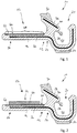
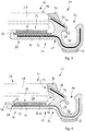
- Fig. 1
- eine Seitenansicht einer ersten Ausführungsform einer Profilleistenanordnung, umfassend eine Profilleiste mit einem Zusatzelement;
- Fig. 2
- die Profilleistenanordnung gemäß
Fig. 1 , zusätzlich umfassend einen Klebeabschnitt; - Fig. 3
- die Profilleistenanordnung gemäß
Fig. 2 , zusätzlich umfassend eine Windschutzscheibe; - Fig. 4
- eine Seitenansicht einer weiteren Ausführungsform einer Profilleistenanordnung, umfassend mindestens ein Zusatzelement in Form einer Versteifungseinlage;
- Fig. 5
- eine Seitenansicht einer weiteren Ausführungsform einer Profilleistenanordnung;
- Fig. 6
- eine Seitenansicht einer weiteren Ausführungsform einer Profilleistenanordnung;
- Fig. 7
- eine perspektivische Ansicht einer Versteifungseinlage der Profilleistenanordnung gemäß
Fig. 6 ; - Fig. 8
- eine Seitenansicht einer weiteren Ausführungsform einer Profilleistenanordnung; und
- Fig. 9
- eine Seitenansicht einer weiteren Ausführungsform einer Profilleistenanordnung, mit einer extrudierten Profilleiste, einem koextrudierten Zusatzelement und mit einem Klebeabschnitt.
- In den
Figuren 1 bis 6 sowie 8 und 9 dargestellte Profilleistenanordnungen sind dort insgesamt jeweils mit dem Bezugszeichen 10 bezeichnet. Die Profilleistenanordnungen 10 umfassen jeweils eine Profilleiste 12, die aus einem Profilmaterial 14 hergestellt ist. Bei dem Profilmaterial 14 handelt es sich um einen Kunststoff, beispielsweise um Polyvinylchlorid (PVC), Blends aus Polyvinylchlorid und Poly(acrylnitril-co-butadien-co-styrol) (PVC/ABS) oder insbesondere um Polypropylen (PP). - Die Profilleisten 12 weisen jeweils einen ersten Verbindungsbereich 16 zur Verbindung mit einer Windschutzscheibe 18 (vergleiche
Figuren 3 und 4 ) auf, sowie einen zweiten Verbindungsbereich 20 zur Verbindung der Profilleiste 12 mit einem an die Windschutzscheibe 18 angrenzenden Bauteil, insbesondere einer Wasserkastenabdeckung. Solche Bauteile sind beispielsweise aus derEP 2 123 497 A1 bekannt und weisen Rastelemente auf, welche in einem U- oder V-förmigen Aufnahmeraum 22 des zweiten Verbindungsbereichs 20 verrastet werden, um das an die Windschutzscheibe angrenzende Bauteil an der Profilleiste 12 festzulegen. - Zur Verbindung des ersten Verbindungsbereichs 16 und des zweiten Verbindungsbereichs 20 weisen die Profilleisten 12 jeweils einen zentralen Abschnitt 24 auf.
- Es ist möglich, dass die Profilleisten 12 zusätzliche Funktionsabschnitte aufweisen, welche aus einem anderen Material hergestellt sind als das Profilmaterial 14. Bei solchen Funktionsabschnitten kann es sich beispielsweise um einen Abstützabschnitt 26 zur Abstützung des zweiten Verbindungsbereichs 20 an einem Fahrzeugbauteil handeln. Es kann sich beispielsweise auch um einen dem zweiten Verbindungsbereich 20 zugeordneten Rastkörper 28 handeln. Es kann sich auch um einen Dichtkörper 30 handeln, der zur dichtenden Anlage gegen eine Windschutzscheibe und gegen das an die Windschutzscheibe angrenzende Bauteil dient.
- Es ist möglich und bevorzugt, dass die Profilleisten 12 entlang ihres Verlaufs zwischen dem ersten Verbindungsbereich 16 und dem zweiten Verbindungsbereich 20 mittels mindestens einer Versteifungseinlage 32 verstärkt sind.
- Bei den Versteifungseinlagen 32 handelt es sich insbesondere um profilierte Flachkörper aus Stahl, einer Stahllegierung, Aluminium oder einer Aluminiumlegierung. Alternativ hierzu kann die Versteifungseinlage 32 aus einem Kunststoff- oder Faserkunststoffverbundmaterial gebildet sein und insbesondere einen Kunststoff umfassen, der eine höhere Oberflächenenergie aufweist als das Profilmaterial. Es ist auch möglich, dass eine Versteifungseinlage 32 sich nur und ausschließlich innerhalb eines Verbindungsbereichs 16 bzw. 20 erstreckt.
- Darüber hinaus ist es bei Anordnung eines Dichtkörpers 30 bevorzugt, dass ein Trägerabschnitt 38 der Profilleiste 12, welcher den Dichtkörper 30 trägt, ebenfalls mittels einer Versteifungseinlage 40 verstärkt ist.
- Die Windschutzscheibe 18 weist einen in ihrer Einbaulage an einem Kraftfahrzeug unteren Randbereich 42 auf, der mit dem ersten Verbindungsbereich 16 der Profilleiste 12 zusammenwirkt. Der Randbereich 42 weist eine Außenseite 44, eine Stirnseite 46 und eine Innenseite 48 auf, vergleiche
Figuren 3 und 4 . - Der erste Verbindungsbereich 16 der Profilleiste 12 weist zumindest einen unteren Verbindungsabschnitt 50 auf, der mit der Innenseite 48 des Randbereichs 42 der Windschutzscheibe 18 zusammenwirkt. Es ist möglich, dass zusätzlich ein seitlicher Verbindungsabschnitt 52 vorgesehen ist, der mit der Stirnseite 46 des Randbereichs 42 der Windschutzscheibe 18 zusammenwirkt.
- Es kann auch ein oberer Verbindungsabschnitt vorgesehen sein, der mit der Außenseite 44 des Randbereichs 42 der Windschutzscheibe 18 zusammenwirkt und sich vorzugsweise parallel und beabstandet zu dem unteren Verbindungsabschnitt 50 erstreckt, wobei ein unterer Verbindungsabschnitt 50, ein seitlicher Verbindungsabschnitt 52 und ein oberer Verbindungsabschnitt gemeinsam in dem ersten Verbindungsbereich 16 ein "U-Profil" bilden, das den Randbereich 42 einer Windschutzscheibe 18 umklammert.
- Die Profilleisten 12 weisen in dem ersten Verbindungsbereich 16 einen Oberflächenabschnitt 58 auf, der frei ist von Profilmaterial 14. Der Oberflächenabschnitt 58 wird anstelle des Profilmaterials 14 von einer Oberfläche 60 eines Zusatzelements 62 gebildet.
- In dem in oder an dem ersten Verbindungsbereich 16 angeordneten Zustand des Randbereichs 42 der Windschutzscheibe 18 ist die Oberfläche 60 dem Randbereich 42 zugewandt. Die an dem unteren Verbindungsabschnitt 50 vorgesehene Oberfläche 60 ist der Innenseite 48 des Randbereichs 42 der Windschutzscheibe zugewandt (vergleiche
Figuren 1 bis 6 sowie 8 und 9). Wenn eine Oberfläche 60 an einem seitlichen Verbindungsabschnitt 52 angeordnet ist, ist diese Oberfläche 60 der Stirnseite 46 des Randbereichs 42 der Windschutzscheibe 18 zugewandt. Wenn eine Oberfläche 60 an einem (nicht dargestellten) oberen Verbindungsabschnitt angeordnet ist, ist diese Oberfläche 60 der Außenseite 44 des Randbereichs 42 der Windschutzscheibe 18 zugewandt. - Bei dem Zusatzelement 62 gemäß
Figuren 1 bis 3 handelt es sich um ein Zusatzelement, welches separat zu Versteifungseinlagen 32, 40 der Profilleistenanordnungen 10 bereitgestellt ist und an der Profilleiste 12 zu den Versteifungseinlagen 32, 40 beabstandet angeordnet ist. Dieses Zusatzelement 62 erstreckt sich ausschließlich in dem freien Oberflächenabschnitt 58. - Bei dem Zusatzelement 62 handelt es sich insbesondere um einen ebenen Flachkörper. Der Flachkörper ist beispielsweise aus einem metallischen Material hergestellt, insbesondere aus Stahl, einer Stahllegierung, Aluminium oder einer Aluminiumlegierung. Alternativ hierzu kann das Zusatzelement 62 aus einem Kunststoff- oder Faserkunststoffverbundmaterial gebildet sein und insbesondere einen Kunststoff umfassen, der eine höhere Oberflächenenergie aufweist als das Profilmaterial 14. Es kann sein, dass das Zusatzelement 62 selbst die Oberfläche 60 bildet, oder aber eine Beschichtung des Zusatzelements 62.
- Für eine stoffschlüssige Verbindung zwischen dem Zusatzelement 62 und dem Randbereich 42 der Windschutzscheibe 18 ist ein Klebeabschnitt 64 vorgesehen, welcher insbesondere durch ein doppelseitiges Klebeband 66 gebildet ist. Das Klebeband 66 weist voneinander abgewandte Klebeseiten auf. Eine erste Klebeseite wirkt mit der Oberfläche 60 des Zusatzelements 62 zusammen, und eine von der ersten Seite abgewandte zweite Klebeseite wirkt mit der Innenseite 48 des Randbereichs 42 der Windschutzscheibe 18 zusammen.
- Es ist möglich, dass die Profilleisten 12 keine Versteifungseinlagen 32, 40 aufweisen. Für den Fall, dass mindestens eine Versteifungseinlage 32, 40 vorgesehen ist, ist es möglich, dass eine solche Versteifungseinlage 32 und/oder 40 ein Zusatzelement 62 bildet. Solche Anordnungen sind in den
Figuren 4 bis 6 und 8 dargestellt. - Beispielsweise ist eine Versteifungseinlage 32 vorgesehen, die in das Material 14 der Profilleiste 12 eingebettet ist (vergleiche
Fig. 4 ). In einem Oberflächenabschnitt 58 liegt die Oberfläche 60 der Versteifungseinlage 32 oder einer Beschichtung der Versteifungseinlage 32 frei, sodass die Oberfläche der Versteifungseinlage 32 oder eine Beschichtung der Versteifungseinlage 32 mit einem Klebeabschnitt 64, insbesondere mit einem doppelseitigen Klebeband 66, versehen werden kann. - Es ist bevorzugt, dass ein freies Ende 68 der Versteifungseinlage 32 sowohl auf seiner Unterseite als auch auf seiner Oberseite mit Profilmaterial 14 bedeckt ist und somit zumindest ein Teilbereich der Versteifungseinlage 32 in dem Profilmaterial 14 der Profilleiste 12 verankert ist. Dies gilt in entsprechender Weise für einen dem zweiten Verbindungsbereich 20 zugewandten Abschnitt 70 der Versteifungseinlage 32.
- Bei dem in
Figur 4 dargestellten Ausführungsbeispiel variiert die Stärke des Profilmaterials 14 entlang des Verlaufs des unteren Verbindungsabschnitts 50 im Querschnitt gesehen. - Es ist auch möglich, dass die Materialstärke des unteren Verbindungsabschnitts 50 nicht variiert, wobei gleichzeitig eine Versteifungseinlage 32 als Zusatzelement genutzt wird, vergleiche
Figuren 5, 6 und8 . - In dem in
Figur 5 dargestellten Ausführungsbeispiel erstreckt sich die Versteifungseinlage 32, welche ein Zusatzelement 62 bildet, entlang einer geraden Ebene und ist in diesem Bereich lediglich auf einer Seite mit Profilmaterial 14 bedeckt. Um eine Verankerung der Versteifungseinlage 32 in dem Profilmaterial 14 zu verbessern, kann es vorgesehen sein, dass die Versteifungseinlage 32 eine Perforierung 72 aufweist, wodurch die Möglichkeit geschaffen wird, dass das Profilmaterial 14 die Versteifungseinlage 32 durchdringt, vergleicheFiguren 6 und7 . Vorzugsweise ist die Perforierung 72 dem zentralen Abschnitt 24 der Profilleiste 12 zugeordnet. - Eine weitere bevorzugte Möglichkeit, eine Versteifungseinlage 32, die ein Zusatzelement bildet, in dem Profilmaterial 14 der Profilleiste 12 zu verankern, besteht darin, dass zumindest ein freies Ende 68 und/oder ein dem zweiten Verbindungsbereich 20 zugewandter Abschnitt 70 der Versteifungseinlage 32 sowohl auf der Unterseite als auch auf der Oberseite mit Profilmaterial 14 bedeckt ist oder sind, vergleiche
Figur 8 . Ein Zusatzelement 62 kann in diesem Fall dadurch geschaffen werden, dass die Versteifungseinlage 32 nicht entlang ihres gesamten Verlaufs vom freien Ende 68 bis hin zum Abschnitt 70 in das Profilmaterial 14 eingebettet ist, sondern in dem Bereich eines freien Oberflächenabschnitts 58 lediglich auf einer Unterseite mit Profilmaterial 14 bedeckt ist. Dies kann beispielsweise dadurch erreicht werden, dass die Versteifungseinlage 32 entlang ihres Verlaufs zwischen dem freien Ende 68 und dem Abschnitt 70 eine Überhöhung aufweist, sodass die der Unterseite gegenüberliegende Oberseite der Versteifungseinlage 32 eine Oberfläche 60 bildet, die von Profilmaterial 14 frei ist. Auf diese Weise bildet die Versteifungseinlage 32 in diesem Bereich ein Zusatzelement 62, welches vorzugsweise zur Anordnung eines doppelseitigen Klebebands 66 dient oder an welchem ein doppelseitiges Klebeband 66 angeklebt ist. - Insbesondere bei einem von einer Versteifungseinlage 32, 40 unabhängig bereitgestellten Zusatzelement 62 kann es sich auch um einen Materialabschnitt aus Kunststoff handeln, der vorzugsweise mit dem Profilmaterial 14 der Profilleiste 12 koextrudiert ist, vergleiche
Figur 9 .
Claims (15)
- Profilleistenanordnung (10), umfassend eine aus einem Profilmaterial (14) hergestellte Profilleiste (12) mit einem ersten Verbindungsbereich (16) zur Verbindung mit einem Randbereich (42) einer Windschutzscheibe (18) eines Kraftfahrzeugs und mit einem zweiten Verbindungsbereich (20) zur Verbindung mit einem an die Windschutzscheibe (18) angrenzenden Bauteil, dadurch gekennzeichnet, dass der erste Verbindungsbereich (16) einen unteren Verbindungsabschnitt (50) aufweist, der mit einer Innenseite (48) des Randbereichs (42) der Windschutzscheibe (18) zusammenwirkt und der mindestens einen von dem Profilmaterial (14) freien Oberflächenabschnitt (58) aufweist, wobei der freie Oberflächenabschnitt (58) durch die Oberfläche (60) eines Zusatzelements (62) gebildet ist, die aus einem anderen Material besteht als die Profilleiste (12).
- Profilleistenanordnung (10) nach Anspruch 1, dadurch gekennzeichnet, dass das Zusatzelement (62) aus einem Kunststoffmaterial, aus einem Faserkunststoffverbundmaterial oder aus einem Metall besteht.
- Profilleistenanordnung (10) nach einem der voranstehenden Ansprüche, dadurch gekennzeichnet, dass das Zusatzelement (62) eine Beschichtung aufweist.
- Profilleistenanordnung (10) nach einem der voranstehenden Ansprüche, dadurch gekennzeichnet, dass der erste Verbindungsbereich (16) einen seitlichen Verbindungsabschnitt (52) aufweist, der mit einer Stirnseite (46) des Randbereichs (42) der Windschutzscheibe (18) zusammenwirkt, und/oder dass der erste Verbindungsbereich (16) einen oberen Verbindungsabschnitt aufweist, der mit einer Außenseite (44) des Randbereichs (42) der Windschutzscheibe (18) zusammenwirkt, und dass der mindestens eine freie Oberflächenabschnitt (58) an dem seitlichen Verbindungsabschnitt (52) und/oder dem oberen Verbindungsabschnitt angeordnet ist.
- Profilleistenanordnung (10) nach einem der voranstehenden Ansprüche, dadurch gekennzeichnet, dass der freie Oberflächenabschnitt (58) dem Randbereich (42) der Windschutzscheibe (18) zugewandt ist.
- Profilleistenanordnung (10) nach einem der voranstehenden Ansprüche, dadurch gekennzeichnet, dass der zweite Verbindungsbereich (20) einen im Profil U-oder V-förmigen Aufnahmeraum (22) zur Aufnahme eines Rastelements des an die Windschutzscheibe (18) angrenzenden Bauteils, insbesondere einer Wasserkastenabdeckung, aufweist.
- Profilleistenanordnung (10) nach einem der voranstehenden Ansprüche, dadurch gekennzeichnet, dass sich das Zusatzelement (62) ausschließlich in dem freien Oberflächenabschnitt (58) erstreckt.
- Profilleistenanordnung (10) nach einem der Ansprüche 1 bis 6, dadurch gekennzeichnet, dass in dem Bereich eines Teilabschnitts des Zusatzelements dieses sowohl auf seiner Unterseite als auch auf seiner Oberseite mit Profilmaterial (14) bedeckt ist.
- Profilleistenanordnung (10) nach Anspruch 8, dadurch gekennzeichnet, dass der Teilabschnitt durch ein freies Ende (68) des Zusatzelements und/oder durch einen dem zweiten Verbindungsbereich (20) zugewandten Abschnitt (70) des Zusatzelements gebildet ist.
- Profilleistenanordnung (10) nach einem der voranstehenden Ansprüche, dadurch gekennzeichnet, dass die Profilleiste (12) einen zentralen Abschnitt (24) aufweist, der den ersten Verbindungsbereich (16) und den zweiten Verbindungsbereich (20) miteinander verbindet, und dass das Zusatzelement im Bereich des zentralen Abschnitts (24) Durchbrüche aufweist, insbesondere in Form einer Perforierung (72).
- Profilleistenanordnung (10) nach einem der voranstehenden Ansprüche, dadurch gekennzeichnet, dass das Zusatzelement durch eine Versteifungseinlage (32, 40) gebildet ist, welche die Profilleiste (12) versteift.
- Profilleistenanordnung (10) nach einem der voranstehenden Ansprüche, dadurch gekennzeichnet, dass zumindest ein Teilbereich des freien Oberflächenabschnitts (58) von einem Klebeabschnitt (64) überdeckt ist, der zur Klebeverbindung mit dem Randbereich (42) der Windschutzscheibe (18) dient.
- Profilleistenanordnung (10) nach Anspruch 12, dadurch gekennzeichnet, dass der Klebeabschnitt (64) durch ein doppelseitiges Klebeband (66) gebildet ist.
- Verfahren zur Herstellung einer Profilleistenanordnung (10) nach einem der voranstehenden Ansprüche, dadurch gekennzeichnet, dass die Profilleiste (12) und das Zusatzelement (62) voneinander unabhängig hergestellt und anschließend miteinander verbunden werden.
- Verfahren zur Herstellung einer Profilleistenanordnung (10) nach einem der Ansprüche 1 bis 13, dadurch gekennzeichnet, dass das Profilmaterial (14) der Profilleiste (12) extrudiert wird, dass das Zusatzelement (62) oder ein Material zur Herstellung des Zusatzelements (62) während der Extrusion des Profilmaterials (14) zugeführt wird und dass das Profilmaterial (14) in einem mit dem Zusatzelement (62) zumindest abschnittsweise verbundenen Zustand erstarrt.
Priority Applications (1)
| Application Number | Priority Date | Filing Date | Title |
|---|---|---|---|
| PL17158796T PL3219525T3 (pl) | 2016-03-16 | 2017-03-02 | Układ profilowanej listwy |
Applications Claiming Priority (1)
| Application Number | Priority Date | Filing Date | Title |
|---|---|---|---|
| DE102016104848.8A DE102016104848A1 (de) | 2016-03-16 | 2016-03-16 | Profilleistenanordnung |
Publications (3)
| Publication Number | Publication Date |
|---|---|
| EP3219525A2 true EP3219525A2 (de) | 2017-09-20 |
| EP3219525A3 EP3219525A3 (de) | 2017-11-15 |
| EP3219525B1 EP3219525B1 (de) | 2020-05-20 |
Family
ID=58264391
Family Applications (1)
| Application Number | Title | Priority Date | Filing Date |
|---|---|---|---|
| EP17158796.7A Not-in-force EP3219525B1 (de) | 2016-03-16 | 2017-03-02 | Profilleistenanordnung |
Country Status (4)
| Country | Link |
|---|---|
| US (1) | US10752100B2 (de) |
| EP (1) | EP3219525B1 (de) |
| DE (1) | DE102016104848A1 (de) |
| PL (1) | PL3219525T3 (de) |
Families Citing this family (3)
| Publication number | Priority date | Publication date | Assignee | Title |
|---|---|---|---|---|
| DE102013204820A1 (de) * | 2013-03-19 | 2014-09-25 | Elkamet Kunststofftechnik Gmbh | Profilelement zum Verbinden einer Fahrzeugscheibe mit einem Abdeckteil und Profilelementbaugruppe |
| WO2021147791A1 (en) * | 2020-01-20 | 2021-07-29 | Saint-Gobain Glass France | Sealing system for connecting drainage device to vehicle window glass |
| CN112238740B (zh) * | 2020-01-20 | 2025-09-05 | 法国圣戈班安全玻璃公司 | 一种用于连接排水装置和车窗玻璃的密封系统 |
Citations (5)
| Publication number | Priority date | Publication date | Assignee | Title |
|---|---|---|---|---|
| DE102008003252A1 (de) | 2008-01-04 | 2009-07-16 | Rehau Ag + Co | Scheibenanordnung |
| EP2123497A1 (de) | 2008-05-23 | 2009-11-25 | Elkamet Kunststofftechnik GmbH | Profilelement zum Verbinden einer Fahrzeugscheibe mit einem Wasserkasten |
| DE202008013133U1 (de) | 2008-10-02 | 2010-02-25 | Rehau Ag + Co | Scheibenabdichtung |
| DE102012112674A1 (de) | 2012-12-19 | 2014-06-26 | Rehau Ag + Co | Profilelement zum Anschluss eines Anbauteils an eine Fahrzeugscheibe sowie Verfahren zur Herstellung eines Profilelements |
| DE102012112663A1 (de) | 2012-12-19 | 2014-06-26 | Rehau Ag + Co. | Abdichtungsprofil zum Anschluss eines Anbauteils an eine Fahrzeugscheibe sowie Verfahren zur Herstellung eines Abdichtungsprofils |
Family Cites Families (17)
| Publication number | Priority date | Publication date | Assignee | Title |
|---|---|---|---|---|
| IT1143384B (it) * | 1981-02-12 | 1986-10-22 | Comind Spa Azienda Ages | Perfezionamento ai sistemi di collegamento dei cristalli fissi di veicoli in genere particolarmente autovetture |
| US4505965A (en) | 1981-07-10 | 1985-03-19 | Wolfgang Zipperle | Rain protective molding for automobiles |
| DE3140366C2 (de) * | 1981-10-10 | 1985-02-14 | Metzeler Kautschuk GmbH, 8000 München | Verfahren und Vorrichtung zur Herstellung eines Einbauteils, bestehend aus einer Scheibe und einem Dichtungs- und Halterahmen |
| DE3735133A1 (de) * | 1987-10-16 | 1989-05-03 | Bayerische Motoren Werke Ag | Kraftfahrzeug, insbesondere personenkraftwagen |
| FR2638780B1 (fr) * | 1988-11-08 | 1991-02-15 | Mesnel Sa Ets | Profile pour le guidage et l'etancheite d'une glace mobile, notamment de porte d'automobile, et son procede de fabrication |
| US5261721A (en) * | 1991-10-18 | 1993-11-16 | Donnelly Corporation | Vehicular window assembly with weather seal |
| DE20008555U1 (de) * | 2000-05-12 | 2000-08-17 | Elkamet Kunststofftechnik GmbH, 35216 Biedenkopf | Abdichtungs-Anordnung für Fahrzeugscheiben |
| ES2190320B1 (es) * | 2000-12-19 | 2004-06-01 | Industrie Ilpea España, S.A. | Junta de estanqueidad para parabrisas de automoviles. |
| US20080191508A1 (en) * | 2007-02-12 | 2008-08-14 | Kolokowski Paul J | Connecting a trim molding to windshield glass |
| DE202008016217U1 (de) * | 2008-12-09 | 2009-04-02 | Elkamet Kunststofftechnik Gmbh | Profilelement |
| DE102009010015A1 (de) * | 2009-02-21 | 2010-08-26 | Henniges Automotive Gmbh & Co. Kg | Autoglasscheibe mit auf den Rand aufgeklebtem Leistenteil |
| DE102012112662A1 (de) * | 2012-12-19 | 2014-07-10 | Rehau Ag + Co. | System zum Montieren eines Anbauteils an eine Fahrzeugscheibe, Anordnung mit einem System, sowie Verfahren zum Montieren eines Anbauteils an eine Fahrzeugscheibe |
| DE102013204820A1 (de) * | 2013-03-19 | 2014-09-25 | Elkamet Kunststofftechnik Gmbh | Profilelement zum Verbinden einer Fahrzeugscheibe mit einem Abdeckteil und Profilelementbaugruppe |
| CA2924363C (en) * | 2013-09-24 | 2019-07-02 | Saint-Gobain Glass France | Sealing arrangement for a motor vehicle window pane |
| CN104085282A (zh) * | 2014-07-02 | 2014-10-08 | 福耀玻璃工业集团股份有限公司 | 一种车窗玻璃的密封系统 |
| DE202014106202U1 (de) * | 2014-12-22 | 2016-03-23 | Rehau Ag + Co | Verbindungs-Anordung für eine Fahrzeugscheibe, insbesondere für eine Windschutzscheibe |
| DE202014106204U1 (de) | 2014-12-22 | 2015-03-10 | Rehau Ag + Co | Abdichtungsanordnung für eine Fahrzeugscheibe |
-
2016
- 2016-03-16 DE DE102016104848.8A patent/DE102016104848A1/de not_active Withdrawn
-
2017
- 2017-03-02 PL PL17158796T patent/PL3219525T3/pl unknown
- 2017-03-02 EP EP17158796.7A patent/EP3219525B1/de not_active Not-in-force
- 2017-03-15 US US15/459,124 patent/US10752100B2/en not_active Expired - Fee Related
Patent Citations (5)
| Publication number | Priority date | Publication date | Assignee | Title |
|---|---|---|---|---|
| DE102008003252A1 (de) | 2008-01-04 | 2009-07-16 | Rehau Ag + Co | Scheibenanordnung |
| EP2123497A1 (de) | 2008-05-23 | 2009-11-25 | Elkamet Kunststofftechnik GmbH | Profilelement zum Verbinden einer Fahrzeugscheibe mit einem Wasserkasten |
| DE202008013133U1 (de) | 2008-10-02 | 2010-02-25 | Rehau Ag + Co | Scheibenabdichtung |
| DE102012112674A1 (de) | 2012-12-19 | 2014-06-26 | Rehau Ag + Co | Profilelement zum Anschluss eines Anbauteils an eine Fahrzeugscheibe sowie Verfahren zur Herstellung eines Profilelements |
| DE102012112663A1 (de) | 2012-12-19 | 2014-06-26 | Rehau Ag + Co. | Abdichtungsprofil zum Anschluss eines Anbauteils an eine Fahrzeugscheibe sowie Verfahren zur Herstellung eines Abdichtungsprofils |
Also Published As
| Publication number | Publication date |
|---|---|
| PL3219525T3 (pl) | 2020-11-16 |
| US10752100B2 (en) | 2020-08-25 |
| DE102016104848A1 (de) | 2017-09-21 |
| EP3219525B1 (de) | 2020-05-20 |
| EP3219525A3 (de) | 2017-11-15 |
| US20170267084A1 (en) | 2017-09-21 |
Similar Documents
| Publication | Publication Date | Title |
|---|---|---|
| EP3219529B1 (de) | Profilleistenanordnung | |
| EP2613104B1 (de) | Verfahren zum Herstellen eines Befestigungssystems, insbesondere für Bauelemente fotovoltaischer Anlagen | |
| DE202006003857U1 (de) | Stützleiste für eine Verbundplatte | |
| EP2354410B1 (de) | Schaumstoff-dichtstreifen und fensterlaibung mit schaumstoff-dichtstreifen | |
| EP3219525B1 (de) | Profilleistenanordnung | |
| DE102011121381B4 (de) | Verfahren zur Herstellung eines Aufprallquerträgers sowie Aufprallquerträger | |
| WO2013156166A1 (de) | Verfahren zum herstellen grosser leichtbleche | |
| DE4214489C2 (de) | Dichtungsprofilkörper für einen Kfz-Flansch | |
| DE202007001369U1 (de) | Aufprallquerträger für eine Kraftfahrzeugkarosserie | |
| EP0108879A2 (de) | Fahrzeugkarosserie mit zumindest einer daran durch ein Haftmittel befestigten Zier- oder Schutzleiste | |
| EP2750931B1 (de) | Verfahren zur herstellung eines verkleidungsteil | |
| DE102014118029A1 (de) | Profilstrang und verfahren zum herstellen eines profilstrangs | |
| DE8230187U1 (de) | Kotfluegel in blechkonstruktionsbauweise fuer insbesondere lastkraftfahrzeuge | |
| DE202009000448U1 (de) | Fliese für einen Wand-, Boden- oder Deckenbelag | |
| EP3219895B1 (de) | Schiebetüranordnung und schiebeflügel einer schiebetüranordnung | |
| DE102008006204A1 (de) | Fahrzeugkupplung | |
| WO2013041177A1 (de) | Dachrahmenteil einer karosserie eines personenkraftwagens | |
| DE202015009613U1 (de) | Selbstführende Schneidvorrichtung | |
| DE102014103037A1 (de) | Nutzfahrzeug | |
| DE102006022926B4 (de) | Fahrzeug-Dachteil mit wenigstens einer Kunststoffschicht und einem damit verbundenen Rahmen | |
| DE19958720A1 (de) | Plattenförmiges Element | |
| EP3597824A1 (de) | Schwellenbesohlung | |
| DE102016215461A1 (de) | Glasdeckeleinheit für ein Dachsystem eines Kraftfahrzeugs | |
| EP4065332B1 (de) | Verwendung eines endlosbandes als trägerband oder prozessband | |
| DE102008024383B4 (de) | Verstärkungseinlage für einen Dichtungsstrang |
Legal Events
| Date | Code | Title | Description |
|---|---|---|---|
| PUAI | Public reference made under article 153(3) epc to a published international application that has entered the european phase |
Free format text: ORIGINAL CODE: 0009012 |
|
| STAA | Information on the status of an ep patent application or granted ep patent |
Free format text: STATUS: THE APPLICATION HAS BEEN PUBLISHED |
|
| AK | Designated contracting states |
Kind code of ref document: A2 Designated state(s): AL AT BE BG CH CY CZ DE DK EE ES FI FR GB GR HR HU IE IS IT LI LT LU LV MC MK MT NL NO PL PT RO RS SE SI SK SM TR |
|
| AX | Request for extension of the european patent |
Extension state: BA ME |
|
| PUAL | Search report despatched |
Free format text: ORIGINAL CODE: 0009013 |
|
| AK | Designated contracting states |
Kind code of ref document: A3 Designated state(s): AL AT BE BG CH CY CZ DE DK EE ES FI FR GB GR HR HU IE IS IT LI LT LU LV MC MK MT NL NO PL PT RO RS SE SI SK SM TR |
|
| AX | Request for extension of the european patent |
Extension state: BA ME |
|
| RIC1 | Information provided on ipc code assigned before grant |
Ipc: B60J 10/70 20160101ALI20171009BHEP Ipc: B60J 10/35 20160101ALI20171009BHEP Ipc: B60J 10/18 20160101ALI20171009BHEP Ipc: B60J 10/32 20160101ALI20171009BHEP Ipc: B60J 10/21 20160101ALI20171009BHEP Ipc: B60J 1/02 20060101AFI20171009BHEP |
|
| STAA | Information on the status of an ep patent application or granted ep patent |
Free format text: STATUS: REQUEST FOR EXAMINATION WAS MADE |
|
| 17P | Request for examination filed |
Effective date: 20180514 |
|
| RBV | Designated contracting states (corrected) |
Designated state(s): AL AT BE BG CH CY CZ DE DK EE ES FI FR GB GR HR HU IE IS IT LI LT LU LV MC MK MT NL NO PL PT RO RS SE SI SK SM TR |
|
| RIN1 | Information on inventor provided before grant (corrected) |
Inventor name: SCHOCH, ANDREAS Inventor name: ORTMUELLER, MICHAEL Inventor name: DEUSSEN, MARTIN |
|
| GRAP | Despatch of communication of intention to grant a patent |
Free format text: ORIGINAL CODE: EPIDOSNIGR1 |
|
| STAA | Information on the status of an ep patent application or granted ep patent |
Free format text: STATUS: GRANT OF PATENT IS INTENDED |
|
| INTG | Intention to grant announced |
Effective date: 20191217 |
|
| GRAS | Grant fee paid |
Free format text: ORIGINAL CODE: EPIDOSNIGR3 |
|
| GRAA | (expected) grant |
Free format text: ORIGINAL CODE: 0009210 |
|
| STAA | Information on the status of an ep patent application or granted ep patent |
Free format text: STATUS: THE PATENT HAS BEEN GRANTED |
|
| AK | Designated contracting states |
Kind code of ref document: B1 Designated state(s): AL AT BE BG CH CY CZ DE DK EE ES FI FR GB GR HR HU IE IS IT LI LT LU LV MC MK MT NL NO PL PT RO RS SE SI SK SM TR |
|
| REG | Reference to a national code |
Ref country code: GB Ref legal event code: FG4D Free format text: NOT ENGLISH |
|
| REG | Reference to a national code |
Ref country code: CH Ref legal event code: EP |
|
| REG | Reference to a national code |
Ref country code: DE Ref legal event code: R096 Ref document number: 502017005358 Country of ref document: DE |
|
| REG | Reference to a national code |
Ref country code: AT Ref legal event code: REF Ref document number: 1272378 Country of ref document: AT Kind code of ref document: T Effective date: 20200615 |
|
| REG | Reference to a national code |
Ref country code: LT Ref legal event code: MG4D |
|
| REG | Reference to a national code |
Ref country code: NL Ref legal event code: MP Effective date: 20200520 |
|
| PG25 | Lapsed in a contracting state [announced via postgrant information from national office to epo] |
Ref country code: SE Free format text: LAPSE BECAUSE OF FAILURE TO SUBMIT A TRANSLATION OF THE DESCRIPTION OR TO PAY THE FEE WITHIN THE PRESCRIBED TIME-LIMIT Effective date: 20200520 Ref country code: IS Free format text: LAPSE BECAUSE OF FAILURE TO SUBMIT A TRANSLATION OF THE DESCRIPTION OR TO PAY THE FEE WITHIN THE PRESCRIBED TIME-LIMIT Effective date: 20200920 Ref country code: NO Free format text: LAPSE BECAUSE OF FAILURE TO SUBMIT A TRANSLATION OF THE DESCRIPTION OR TO PAY THE FEE WITHIN THE PRESCRIBED TIME-LIMIT Effective date: 20200820 Ref country code: GR Free format text: LAPSE BECAUSE OF FAILURE TO SUBMIT A TRANSLATION OF THE DESCRIPTION OR TO PAY THE FEE WITHIN THE PRESCRIBED TIME-LIMIT Effective date: 20200821 Ref country code: FI Free format text: LAPSE BECAUSE OF FAILURE TO SUBMIT A TRANSLATION OF THE DESCRIPTION OR TO PAY THE FEE WITHIN THE PRESCRIBED TIME-LIMIT Effective date: 20200520 Ref country code: LT Free format text: LAPSE BECAUSE OF FAILURE TO SUBMIT A TRANSLATION OF THE DESCRIPTION OR TO PAY THE FEE WITHIN THE PRESCRIBED TIME-LIMIT Effective date: 20200520 Ref country code: PT Free format text: LAPSE BECAUSE OF FAILURE TO SUBMIT A TRANSLATION OF THE DESCRIPTION OR TO PAY THE FEE WITHIN THE PRESCRIBED TIME-LIMIT Effective date: 20200921 |
|
| PG25 | Lapsed in a contracting state [announced via postgrant information from national office to epo] |
Ref country code: LV Free format text: LAPSE BECAUSE OF FAILURE TO SUBMIT A TRANSLATION OF THE DESCRIPTION OR TO PAY THE FEE WITHIN THE PRESCRIBED TIME-LIMIT Effective date: 20200520 Ref country code: HR Free format text: LAPSE BECAUSE OF FAILURE TO SUBMIT A TRANSLATION OF THE DESCRIPTION OR TO PAY THE FEE WITHIN THE PRESCRIBED TIME-LIMIT Effective date: 20200520 Ref country code: RS Free format text: LAPSE BECAUSE OF FAILURE TO SUBMIT A TRANSLATION OF THE DESCRIPTION OR TO PAY THE FEE WITHIN THE PRESCRIBED TIME-LIMIT Effective date: 20200520 Ref country code: BG Free format text: LAPSE BECAUSE OF FAILURE TO SUBMIT A TRANSLATION OF THE DESCRIPTION OR TO PAY THE FEE WITHIN THE PRESCRIBED TIME-LIMIT Effective date: 20200820 |
|
| PG25 | Lapsed in a contracting state [announced via postgrant information from national office to epo] |
Ref country code: AL Free format text: LAPSE BECAUSE OF FAILURE TO SUBMIT A TRANSLATION OF THE DESCRIPTION OR TO PAY THE FEE WITHIN THE PRESCRIBED TIME-LIMIT Effective date: 20200520 Ref country code: NL Free format text: LAPSE BECAUSE OF FAILURE TO SUBMIT A TRANSLATION OF THE DESCRIPTION OR TO PAY THE FEE WITHIN THE PRESCRIBED TIME-LIMIT Effective date: 20200520 |
|
| PG25 | Lapsed in a contracting state [announced via postgrant information from national office to epo] |
Ref country code: SM Free format text: LAPSE BECAUSE OF FAILURE TO SUBMIT A TRANSLATION OF THE DESCRIPTION OR TO PAY THE FEE WITHIN THE PRESCRIBED TIME-LIMIT Effective date: 20200520 Ref country code: EE Free format text: LAPSE BECAUSE OF FAILURE TO SUBMIT A TRANSLATION OF THE DESCRIPTION OR TO PAY THE FEE WITHIN THE PRESCRIBED TIME-LIMIT Effective date: 20200520 Ref country code: DK Free format text: LAPSE BECAUSE OF FAILURE TO SUBMIT A TRANSLATION OF THE DESCRIPTION OR TO PAY THE FEE WITHIN THE PRESCRIBED TIME-LIMIT Effective date: 20200520 Ref country code: ES Free format text: LAPSE BECAUSE OF FAILURE TO SUBMIT A TRANSLATION OF THE DESCRIPTION OR TO PAY THE FEE WITHIN THE PRESCRIBED TIME-LIMIT Effective date: 20200520 Ref country code: CZ Free format text: LAPSE BECAUSE OF FAILURE TO SUBMIT A TRANSLATION OF THE DESCRIPTION OR TO PAY THE FEE WITHIN THE PRESCRIBED TIME-LIMIT Effective date: 20200520 Ref country code: RO Free format text: LAPSE BECAUSE OF FAILURE TO SUBMIT A TRANSLATION OF THE DESCRIPTION OR TO PAY THE FEE WITHIN THE PRESCRIBED TIME-LIMIT Effective date: 20200520 Ref country code: IT Free format text: LAPSE BECAUSE OF FAILURE TO SUBMIT A TRANSLATION OF THE DESCRIPTION OR TO PAY THE FEE WITHIN THE PRESCRIBED TIME-LIMIT Effective date: 20200520 |
|
| REG | Reference to a national code |
Ref country code: DE Ref legal event code: R097 Ref document number: 502017005358 Country of ref document: DE |
|
| PG25 | Lapsed in a contracting state [announced via postgrant information from national office to epo] |
Ref country code: SK Free format text: LAPSE BECAUSE OF FAILURE TO SUBMIT A TRANSLATION OF THE DESCRIPTION OR TO PAY THE FEE WITHIN THE PRESCRIBED TIME-LIMIT Effective date: 20200520 |
|
| PLBE | No opposition filed within time limit |
Free format text: ORIGINAL CODE: 0009261 |
|
| STAA | Information on the status of an ep patent application or granted ep patent |
Free format text: STATUS: NO OPPOSITION FILED WITHIN TIME LIMIT |
|
| 26N | No opposition filed |
Effective date: 20210223 |
|
| PG25 | Lapsed in a contracting state [announced via postgrant information from national office to epo] |
Ref country code: SI Free format text: LAPSE BECAUSE OF FAILURE TO SUBMIT A TRANSLATION OF THE DESCRIPTION OR TO PAY THE FEE WITHIN THE PRESCRIBED TIME-LIMIT Effective date: 20200520 |
|
| PG25 | Lapsed in a contracting state [announced via postgrant information from national office to epo] |
Ref country code: MC Free format text: LAPSE BECAUSE OF FAILURE TO SUBMIT A TRANSLATION OF THE DESCRIPTION OR TO PAY THE FEE WITHIN THE PRESCRIBED TIME-LIMIT Effective date: 20200520 |
|
| REG | Reference to a national code |
Ref country code: CH Ref legal event code: PL |
|
| REG | Reference to a national code |
Ref country code: BE Ref legal event code: MM Effective date: 20210331 |
|
| PG25 | Lapsed in a contracting state [announced via postgrant information from national office to epo] |
Ref country code: IE Free format text: LAPSE BECAUSE OF NON-PAYMENT OF DUE FEES Effective date: 20210302 Ref country code: LU Free format text: LAPSE BECAUSE OF NON-PAYMENT OF DUE FEES Effective date: 20210302 Ref country code: LI Free format text: LAPSE BECAUSE OF NON-PAYMENT OF DUE FEES Effective date: 20210331 Ref country code: CH Free format text: LAPSE BECAUSE OF NON-PAYMENT OF DUE FEES Effective date: 20210331 |
|
| PG25 | Lapsed in a contracting state [announced via postgrant information from national office to epo] |
Ref country code: BE Free format text: LAPSE BECAUSE OF NON-PAYMENT OF DUE FEES Effective date: 20210331 |
|
| PGFP | Annual fee paid to national office [announced via postgrant information from national office to epo] |
Ref country code: FR Payment date: 20230320 Year of fee payment: 7 |
|
| REG | Reference to a national code |
Ref country code: AT Ref legal event code: MM01 Ref document number: 1272378 Country of ref document: AT Kind code of ref document: T Effective date: 20220302 |
|
| PG25 | Lapsed in a contracting state [announced via postgrant information from national office to epo] |
Ref country code: HU Free format text: LAPSE BECAUSE OF FAILURE TO SUBMIT A TRANSLATION OF THE DESCRIPTION OR TO PAY THE FEE WITHIN THE PRESCRIBED TIME-LIMIT; INVALID AB INITIO Effective date: 20170302 |
|
| PGFP | Annual fee paid to national office [announced via postgrant information from national office to epo] |
Ref country code: PL Payment date: 20230202 Year of fee payment: 7 Ref country code: GB Payment date: 20230313 Year of fee payment: 7 |
|
| P01 | Opt-out of the competence of the unified patent court (upc) registered |
Effective date: 20230515 |
|
| PG25 | Lapsed in a contracting state [announced via postgrant information from national office to epo] |
Ref country code: CY Free format text: LAPSE BECAUSE OF FAILURE TO SUBMIT A TRANSLATION OF THE DESCRIPTION OR TO PAY THE FEE WITHIN THE PRESCRIBED TIME-LIMIT Effective date: 20200520 |
|
| PG25 | Lapsed in a contracting state [announced via postgrant information from national office to epo] |
Ref country code: AT Free format text: LAPSE BECAUSE OF NON-PAYMENT OF DUE FEES Effective date: 20220302 |
|
| PGFP | Annual fee paid to national office [announced via postgrant information from national office to epo] |
Ref country code: DE Payment date: 20230511 Year of fee payment: 7 |
|
| PG25 | Lapsed in a contracting state [announced via postgrant information from national office to epo] |
Ref country code: MK Free format text: LAPSE BECAUSE OF FAILURE TO SUBMIT A TRANSLATION OF THE DESCRIPTION OR TO PAY THE FEE WITHIN THE PRESCRIBED TIME-LIMIT Effective date: 20200520 |
|
| PG25 | Lapsed in a contracting state [announced via postgrant information from national office to epo] |
Ref country code: MT Free format text: LAPSE BECAUSE OF FAILURE TO SUBMIT A TRANSLATION OF THE DESCRIPTION OR TO PAY THE FEE WITHIN THE PRESCRIBED TIME-LIMIT Effective date: 20200520 |
|
| REG | Reference to a national code |
Ref country code: DE Ref legal event code: R119 Ref document number: 502017005358 Country of ref document: DE |
|
| GBPC | Gb: european patent ceased through non-payment of renewal fee |
Effective date: 20240302 |
|
| PG25 | Lapsed in a contracting state [announced via postgrant information from national office to epo] |
Ref country code: DE Free format text: LAPSE BECAUSE OF NON-PAYMENT OF DUE FEES Effective date: 20241001 |
|
| PG25 | Lapsed in a contracting state [announced via postgrant information from national office to epo] |
Ref country code: GB Free format text: LAPSE BECAUSE OF NON-PAYMENT OF DUE FEES Effective date: 20240302 |
|
| PG25 | Lapsed in a contracting state [announced via postgrant information from national office to epo] |
Ref country code: FR Free format text: LAPSE BECAUSE OF NON-PAYMENT OF DUE FEES Effective date: 20240331 |
|
| PG25 | Lapsed in a contracting state [announced via postgrant information from national office to epo] |
Ref country code: GB Free format text: LAPSE BECAUSE OF NON-PAYMENT OF DUE FEES Effective date: 20240302 Ref country code: FR Free format text: LAPSE BECAUSE OF NON-PAYMENT OF DUE FEES Effective date: 20240331 Ref country code: DE Free format text: LAPSE BECAUSE OF NON-PAYMENT OF DUE FEES Effective date: 20241001 |
|
| PG25 | Lapsed in a contracting state [announced via postgrant information from national office to epo] |
Ref country code: PL Free format text: LAPSE BECAUSE OF NON-PAYMENT OF DUE FEES Effective date: 20240302 |
|
| PG25 | Lapsed in a contracting state [announced via postgrant information from national office to epo] |
Ref country code: TR Free format text: LAPSE BECAUSE OF FAILURE TO SUBMIT A TRANSLATION OF THE DESCRIPTION OR TO PAY THE FEE WITHIN THE PRESCRIBED TIME-LIMIT Effective date: 20200520 |