EP3222796A1 - Échafaudage avec ensemble et procédé de verrouillage - Google Patents
Échafaudage avec ensemble et procédé de verrouillage Download PDFInfo
- Publication number
- EP3222796A1 EP3222796A1 EP17160279.0A EP17160279A EP3222796A1 EP 3222796 A1 EP3222796 A1 EP 3222796A1 EP 17160279 A EP17160279 A EP 17160279A EP 3222796 A1 EP3222796 A1 EP 3222796A1
- Authority
- EP
- European Patent Office
- Prior art keywords
- assembly
- leg
- latch
- platform
- leg assembly
- Prior art date
- Legal status (The legal status is an assumption and is not a legal conclusion. Google has not performed a legal analysis and makes no representation as to the accuracy of the status listed.)
- Granted
Links
Images


Classifications
-
- B—PERFORMING OPERATIONS; TRANSPORTING
- B25—HAND TOOLS; PORTABLE POWER-DRIVEN TOOLS; MANIPULATORS
- B25H—WORKSHOP EQUIPMENT, e.g. FOR MARKING-OUT WORK; STORAGE MEANS FOR WORKSHOPS
- B25H5/00—Tool, instrument or work supports or storage means used in association with vehicles; Workers' supports, e.g. mechanics' creepers
-
- E—FIXED CONSTRUCTIONS
- E04—BUILDING
- E04G—SCAFFOLDING; FORMS; SHUTTERING; BUILDING IMPLEMENTS OR AIDS, OR THEIR USE; HANDLING BUILDING MATERIALS ON THE SITE; REPAIRING, BREAKING-UP OR OTHER WORK ON EXISTING BUILDINGS
- E04G1/00—Scaffolds primarily resting on the ground
- E04G1/02—Scaffolds primarily resting on the ground composed essentially of members elongated in one dimension [1D] only, e.g. poles, lattice masts, with or without end portions of special form, connected together by any means
- E04G1/04—Scaffolds primarily resting on the ground composed essentially of members elongated in one dimension [1D] only, e.g. poles, lattice masts, with or without end portions of special form, connected together by any means the members being exclusively poles, rods, beams, or other members of similar form and simple cross-section
-
- E—FIXED CONSTRUCTIONS
- E04—BUILDING
- E04G—SCAFFOLDING; FORMS; SHUTTERING; BUILDING IMPLEMENTS OR AIDS, OR THEIR USE; HANDLING BUILDING MATERIALS ON THE SITE; REPAIRING, BREAKING-UP OR OTHER WORK ON EXISTING BUILDINGS
- E04G1/00—Scaffolds primarily resting on the ground
- E04G1/28—Scaffolds primarily resting on the ground designed to provide support only at a low height
- E04G1/30—Ladder scaffolds
-
- E—FIXED CONSTRUCTIONS
- E04—BUILDING
- E04G—SCAFFOLDING; FORMS; SHUTTERING; BUILDING IMPLEMENTS OR AIDS, OR THEIR USE; HANDLING BUILDING MATERIALS ON THE SITE; REPAIRING, BREAKING-UP OR OTHER WORK ON EXISTING BUILDINGS
- E04G1/00—Scaffolds primarily resting on the ground
- E04G1/28—Scaffolds primarily resting on the ground designed to provide support only at a low height
- E04G1/32—Other free-standing supports, e.g. using trestles
-
- E—FIXED CONSTRUCTIONS
- E04—BUILDING
- E04G—SCAFFOLDING; FORMS; SHUTTERING; BUILDING IMPLEMENTS OR AIDS, OR THEIR USE; HANDLING BUILDING MATERIALS ON THE SITE; REPAIRING, BREAKING-UP OR OTHER WORK ON EXISTING BUILDINGS
- E04G1/00—Scaffolds primarily resting on the ground
- E04G1/34—Scaffold constructions able to be folded in prismatic or flat parts or able to be turned down
-
- E—FIXED CONSTRUCTIONS
- E04—BUILDING
- E04G—SCAFFOLDING; FORMS; SHUTTERING; BUILDING IMPLEMENTS OR AIDS, OR THEIR USE; HANDLING BUILDING MATERIALS ON THE SITE; REPAIRING, BREAKING-UP OR OTHER WORK ON EXISTING BUILDINGS
- E04G1/00—Scaffolds primarily resting on the ground
- E04G1/28—Scaffolds primarily resting on the ground designed to provide support only at a low height
- E04G1/30—Ladder scaffolds
- E04G2001/302—Ladder scaffolds with ladders supporting the platform
Definitions
- the present invention is related to a scaffold that has a latch assembly attached to a platform which automatically engages with a stud on a first rail of a first leg assembly when the first leg assembly moves to an extended position and locks the first leg assembly into the extended position.
- references to the "present invention” or “invention” relate to exemplary embodiments and not necessarily to every embodiment encompassed by the appended claims.
- the present invention is related to a portable scaffold that has a latch assembly attached to a platform which automatically engages with a stud on a first rail of a first leg assembly when the first leg assembly moves to an extended position and locks the first leg assembly into the extended position and only when a force is applied to the latch assembly is the first leg assembly unlocked and able to move out of the extended position to a folded position.
- Portable scaffolds allow users to easily position the scaffold at desired locations and then climb on them to reach heights that they otherwise could not reach from only standing on the ground. Common reasons the use a portable scaffold is to paint or fix objects or install objects at elevated positions above the ground.
- the portable scaffold must be lightweight so it is easy to carry over reasonable distances, strong to support the weight of a large person who stands on it and stable so it does not collapse or wobble and cause a person standing on it to lose their balance or falloff.
- the scaffold is typically made out of aluminum.
- the legs or rails that support the platform should be able to fold up with the platform so the platform in the folded position can be easily carried without striking walls are objects as it's being carried as well as being able to be stored in a limited space.
- a lightweight and simple latching mechanism is desirable. By being simple, the latch assembly avoids breaking or adding undue weight, or tension or interfering with the use of the scaffold.
- the present invention pertains to a scaffold for a person.
- the scaffold comprises a platform having a first end and an opposing second end and a longitudinal axis upon which the user stands.
- the scaffold comprises a first leg assembly rotatably attached in proximity to the first end of the platform.
- the first leg assembly has a first leg, a second leg in spaced relationship and in parallel with the first leg, and a cross bar attached to the first leg and second leg.
- the first leg assembly rotates between the extended position and the folded position about a first leg assembly pivot axis;
- the scaffold comprises a second leg assembly rotatably attached in proximity to the second end of the platform.
- the scaffold comprises a latch assembly having a latch pivot axis coupled to the platform.
- the scaffold comprises a stud attached to the first leg to which the latch assembly engages when the first leg assembly is moved into the extended position to automatically lock the first leg assembly in the extended position where the latch assembly is in a set position.
- the stud on the first leg disengages from the latch assembly and the first leg assembly is able to rotate about the first leg assembly pivot axis to the folded position.
- the present invention pertains to a method for using a scaffold.
- the method comprises the steps of having a latch assembly coupled to a platform automatically engage with a stud on a first rail of a first leg assembly to lock the first leg assembly in an extended position as the first leg assembly moves from a folded position to the extended position without a person touching the latch assembly, there is the step of placing the platform at a desired location supported by the first rail assembly and a second rail assembly while the first leg assembly is in the extended position, there is the step of having a person stand on the platform while the first leg assembly is in the extended position.
- the present invention pertains to a scaffold on which a person stands.
- the scaffold comprises a platform having a first end and a second end and a longitudinal axis upon which the user stands.
- the scaffold comprises a frame attached in proximity to the first end of the platform.
- the scaffold comprises a first leg assembly having a first leg rotatably attached to the frame, a second leg in spaced relationship and in parallel with the first leg, and a cross bar attached to the first leg and second leg.
- the first leg assembly When the first leg assembly is in an extended position, the first and second legs of the first leg assembly extend essentially perpendicular to the longitudinal axis of the platform and when the first leg assembly is in the folded position, the first and second legs of the first leg assembly extend essentially parallel with the longitudinal axis.
- the first leg assembly rotates between the extended position and the folded position about a first leg assembly pivot axis.
- the scaffold comprises a second leg assembly rotatably attached in proximity to the second end of the platform.
- the scaffold comprises a latch assembly having a latch pivot axis coupled to the platform.
- the latch axis and the first leg assembly pivot axis are in spaced relationship and permanently fixed in place relative to each other.
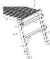
- the scaffold 10 on which a person stands.
- the scaffold 10 comprises a platform 12 having a first end 14 and an opposing second end 16 and a longitudinal axis 18 upon which the user stands.
- the scaffold 10 comprises a first leg assembly 20 rotatably attached in proximity to the first end 14 of the platform 12.
- the first leg assembly 20 has a first leg 22, a second leg 24 in spaced relationship and in parallel with the first leg 22, and a cross bar 26 attached to the first leg 22 and second leg 24.
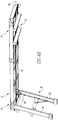
- first leg assembly 20 When the first leg assembly 20 is in an extended position, the first and second legs 22, 24 of the first leg assembly 20 extend essentially perpendicular to the longitudinal axis 18 of the platform 12 and when the first leg assembly 20 is in the folded position, the first and second legs 22, 24 of the first leg assembly 20 extend essentially parallel with the longitudinal axis 18.
- Figure 1 shows the first leg assembly 20 in the extended position.
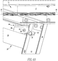
- Figure 4B shows the first leg assembly 20 in the folded position and the second leg assembly 21 in the extended position.
- the first leg assembly 20 rotates between the extended position and the folded position about a first leg assembly pivot axis 28.
- the scaffold 10 comprises a second leg assembly 21 rotatably attached in proximity to the second end 16 of the platform 12.
- the scaffold 10 comprises a latch assembly 30 having a latch pivot axis 32 coupled to the platform 12, as shown in figure 2 .
- the scaffold 10 comprises a stud 34 directly attached to the first leg 22, as shown in figure 4A , to which the latch assembly 30 engages when the first leg assembly 20 is moved into the extended position to automatically lock the first leg assembly 20 in the extended position where the latch assembly 30 is in a set position.
- the latch assembly 30 is moved out of the set position, as shown in figure 5A , the stud 34 on the first leg 22 disengages from the latch assembly 30 and the first leg assembly 20 is able to rotate about the first leg assembly pivot axis 28 to the folded position.
- Figure 3B shows a side view of the scaffold 10 with the first leg assembly 20 separated to show the latch assembly 30, with the second leg assembly 21 in the folded position.
- the latch axis and the first leg assembly pivot axis 28 may be in spaced relationship and permanently fixed in place relative to each other, as shown in figures 1 and 2 .
- the latch assembly 30 may include a latch hook 36 which directly engages and hooks with the stud 34 in the extended position, as shown in figures 3A , 4A and 7 .
- the latch assembly 30 may include a latch pivot 38 about which the latch hook 36 rotates from the set position.
- the latch assembly 30 may include a latch actuator 40 engaged with the latch pivot 38 and the latch hook 36 which moves the latch assembly 30 out of the set position when a force is applied to the latch actuator 40.
- the latch hook 36 may extend inwards towards the platform's middle.
- the latch assembly 30 may include a latch spring 42 positioned about the latch pivot 38 which applies a restoring force to the latch hook 36 and the latch actuator 40 to automatically move the latch assembly 30 to the set position after the latch assembly 30 has moved from the set position, as shown in 5A, 5B and 7.
- the latch hook 36 has an outer surface at its tip which may be curved so that when the first leg assembly 20 is moved to the extended position from the folded position, the stud 34 cams the hook and moves the hook so the stud 34 is able to move past the hook, and then for the stud 34 to be locked in place by the hook after the stud 34 clears the hook under the restoring force of the latch spring 42, as shown in figures 4A and 5B .
- the stud 34 seats in an indentation in the hook when the latch assembly 30 is in the set position and the first leg assembly 20 is in the extended position.
- the restoring force of the latch spring 42 maintains the indentation of the hook on the stud 34 to capture the stud 34 and prevent the hook from moving off of the stud 34 and releasing the study.
- the indentation has a curved shape which conforms to the curved outer perimeter of the stud 34 to ensure a secure fitting to minimize and essentially eliminate any chance the latch hook 36 will separate from the stud 34 in the set position when the leg assembly is in
- the scaffold 10 may include a frame 44 made of plastic or metal, as shown in figures 2 and 3A , to which the first leg 22 is rotatably attached about the first leg assembly pivot axis 28 and to which the platform 12 is attached.
- the frame 44 is disposed between the first leg 22 and the platform 12.
- the frame 44 may have a frame edge 46 that contacts the crossbar when the first leg assembly 20 is in the extended position and which acts as a stop to the first leg assembly 20 at the extended position.
- the frame 44 may have a free wall 48 attached to the frame edge 46 to which the latch pivot 38 extends outwards relative to the longitudinal axis 18 of the platform 12.
- the free wall 48 and the frame edge 46 are disposed below and in spaced relationship with the platform 12 and an end cap at the first end 14 of the platform 12.
- the frame edge 46 forms essentially a right angle with the free wall 48.
- the free wall 48 is connected to and below a frame primary portion 50 through which fasteners 52 fix the frame 44 to the platform 12, and a leg pivot extends to rotatably attached the first leg 22 to the platform 12.
- the stud 34 may have a circular cross section and extends only partly from the inside of the first rail toward the second rail but not contacting the second rail, as shown in figures 4A and 5B .
- the present invention pertains to a method for using a scaffold 10.
- the method comprises the steps of having a latch assembly 30 coupled to a platform 12 automatically engage with a stud 34 on a first rail of a first leg assembly 20 to lock the first leg assembly 20 in an extended position as the first leg assembly 20 moves from a folded position to the extended position without a person touching the latch assembly 30, there is the step of placing the platform 12 at a desired location supported by the first rail assembly and a second rail assembly while the first leg assembly 20 is in the extended position, there is the step of having a person stand on the platform 12 while the first leg assembly 20 is in the extended position.
- the present invention pertains to a scaffold 10 on which a person stands, as shown in figures 1 , 2 and 4A .
- the scaffold 10 comprises a platform 12 having a first end 14 and a second end 16 and a longitudinal axis 18 upon which the user stands.
- the scaffold 10 comprises a frame 44 attached in proximity to the first end 14 of the platform 12.
- the scaffold 10 comprises a first leg assembly 20 having a first leg 22 rotatably attached to the frame 44, a second leg 24 in spaced relationship and in parallel with the first leg 22, and a cross bar 26 attached to the first leg 22 and second leg 24.
- the scaffold 10 comprises a second leg assembly 21 rotatably attached in proximity to the second end 16 of the platform 12.
- the scaffold 10 comprises a latch assembly 30 having a latch pivot axis 32 coupled to the platform 12.
- the latch axis and the first leg assembly pivot axis 28 are in spaced relationship and permanently fixed in place relative to each other.
- the latch assembly 30 automatically locks the first leg assembly 20 in the extended position where the latch assembly 30 is in a set position.
- the first leg assembly 20 is able to rotate about the first leg assembly pivot axis 28 to the folded position.
- the latch pivot 38 is a circular rod made of plastic or metal that extends outwards from the free wall 48 of the frame 44 on the outside of the free wall 48, no more than 2 or 3 inches, and is fixed in place to the inside of the free wall 48, as shown in figure 4A with a fastener closer 93, such as a rivet closure, as is well known in the art.
- the rod of the has a base which contacts the free wall 48, an intermediate portion that extends from the base that has a smaller outside diameter than the outside diameter of the base and a tip at the end of the intermediate portion, with the intermediate portion between the tip and the base.
- the tip has a larger outside diameter than the outside diameter of the intermediate portion.
- the latch actuator 40 may be a flat plate attached to the top of the tip and the base of the rod of the latch pivot 38. A person presses on the plate to rotate the rod and compress the latch spring 42 to cause the latch hook 36 to lift off of the stud 34 and out of the set position so the first leg assembly 20 can disengage from the latch assembly 30 and be moved to the folded position. The person is no longer applying a force impressing on the plate, the latch spring 42 under its restoring force automatically moves the latch assembly 30 back to the set position.
- the stud 34 cams the latch hook 36 up causing the rod to rotate and compress the latch spring 42, allowing the stud 34 to move into the indentation in the hook and seat into the indentation in the hook, where the restoring force of the latch spring 42 causes the indentation of the hook to move down and capture the stud 34.
- the plate By the plate being attached to the top of the tip and the base of the rod, it also captures the latch spring 42 in the groove further prevents the latch spring 42 from coming loose and separating from the rod.
- Figure 6 shows an overhead view of the first end 14 of the platform 12 with the first leg assembly 20 hidden.
- Each end of the axle has a tip 99 which contacts the respective leg and holds the respective leg in place to the platform 12 while allowing the respective leg to rotate between the extended position and the folded position.
- Figure 7 shows the first end 14 of the platform 12 in phantom with the and the outline of the end cap 95 two Phillips screws secure the frame primary portion 50 to the end cap 95, which has Phillips screw holes in the corresponding positions on the end cap 95.
- two on each side of the first leg assembly pivot axis 28 and tip 99 hold the frame primary portion 50 to the platform 12.
Landscapes
- Engineering & Computer Science (AREA)
- Architecture (AREA)
- Mechanical Engineering (AREA)
- Civil Engineering (AREA)
- Structural Engineering (AREA)
- Ladders (AREA)
- Road Signs Or Road Markings (AREA)
Applications Claiming Priority (1)
| Application Number | Priority Date | Filing Date | Title |
|---|---|---|---|
| US15/077,560 US10435894B2 (en) | 2016-03-22 | 2016-03-22 | Scaffold with latch assembly and method |
Publications (2)
| Publication Number | Publication Date |
|---|---|
| EP3222796A1 true EP3222796A1 (fr) | 2017-09-27 |
| EP3222796B1 EP3222796B1 (fr) | 2019-02-27 |
Family
ID=58266484
Family Applications (1)
| Application Number | Title | Priority Date | Filing Date |
|---|---|---|---|
| EP17160279.0A Active EP3222796B1 (fr) | 2016-03-22 | 2017-03-10 | Échafaudage avec ensemble et procédé de verrouillage |
Country Status (6)
| Country | Link |
|---|---|
| US (2) | US10435894B2 (fr) |
| EP (1) | EP3222796B1 (fr) |
| CN (1) | CN107214677B (fr) |
| AU (2) | AU2017200972A1 (fr) |
| CA (1) | CA2959302C (fr) |
| MX (1) | MX378018B (fr) |
Cited By (2)
| Publication number | Priority date | Publication date | Assignee | Title |
|---|---|---|---|---|
| EP3561198A1 (fr) * | 2018-04-24 | 2019-10-30 | Hangzhou Kaida Hardware & Tools Co., Ltd. | Dispositif de plate-forme de travail |
| EP3741927A1 (fr) | 2019-05-24 | 2020-11-25 | CDH Group | Systeme d'assemblage de plateformes sans outils |
Families Citing this family (18)
| Publication number | Priority date | Publication date | Assignee | Title |
|---|---|---|---|---|
| US8997931B2 (en) | 2013-01-10 | 2015-04-07 | Werner Co. | Stepladder with latch stud and method |
| US10801219B2 (en) | 2017-06-19 | 2020-10-13 | Werner Co. | Work scaffold and method |
| CN207436473U (zh) * | 2017-08-04 | 2018-06-01 | 苏州飞华铝制工业有限公司 | 工作台梯柱的解锁结构 |
| CN107981602A (zh) * | 2017-12-11 | 2018-05-04 | 天津市金锚家居用品有限公司 | 一种组合式梯凳 |
| US20190226217A1 (en) | 2018-01-24 | 2019-07-25 | Tricam Industries, Inc. | Work platform |
| CN208534971U (zh) * | 2018-06-21 | 2019-02-22 | 江苏宙际杰智能科技股份有限公司 | 用于梯凳的折叠锁定机构 |
| JP7202108B2 (ja) * | 2018-09-05 | 2023-01-11 | アルインコ株式会社 | 折畳み式作業台におけるロック装置 |
| CN109664255B (zh) * | 2019-01-24 | 2022-04-05 | 常州市武进信和精密机械有限公司 | 表面处理设备用格栅板组件 |
| PH12022550629A1 (en) | 2019-09-18 | 2022-11-21 | Werner Co | Step ladder pivot and lock mechanism |
| US11510526B2 (en) * | 2020-01-10 | 2022-11-29 | Weber-Stephen Products Llc | Portable grills |
| US12168991B2 (en) * | 2020-02-10 | 2024-12-17 | Germans Boada, S.A. | Locking mechanism for folding chassis of electric cutting machines |
| EP3933164B1 (fr) | 2020-07-02 | 2024-02-14 | Werner Co. | Plateforme et procédé de travail en escalier |
| CN213309440U (zh) * | 2020-07-09 | 2021-06-01 | 深圳翼诚科技有限公司 | 一种折叠式马桶垫脚凳 |
| CN112746734B (zh) * | 2020-12-12 | 2022-12-30 | 重庆新久融工程机械设备有限公司 | 一种折叠式脚手架 |
| US12497789B2 (en) * | 2021-03-02 | 2025-12-16 | Werner Co. | Interlocking work platform system |
| USD1047872S1 (en) * | 2022-01-14 | 2024-10-22 | Tianjin Jinmao Houseware Products Co., Ltd | Platform ladder |
| US11868601B2 (en) | 2022-05-10 | 2024-01-09 | Apple Inc. | Devices, methods, and graphical user interfaces for providing notifications and application information |
| CN115045491B (zh) * | 2022-08-04 | 2023-07-21 | 甘肃第四建设集团有限责任公司 | 一种配载式可监控调节的脚手架施工装置 |
Citations (4)
| Publication number | Priority date | Publication date | Assignee | Title |
|---|---|---|---|---|
| JP3030253B2 (ja) * | 1996-09-02 | 2000-04-10 | アルインコ株式会社 | 作業台 |
| JP2002201794A (ja) * | 2000-12-28 | 2002-07-19 | Nikkei Products Co | 作業台 |
| JP2004011126A (ja) * | 2002-06-03 | 2004-01-15 | Pica Corp | 足場台ユニット |
| EP2000612A2 (fr) * | 2007-06-05 | 2008-12-10 | Lampe Holding B.V. | Échafaudage avec jambe verrouillable |
Family Cites Families (12)
| Publication number | Priority date | Publication date | Assignee | Title |
|---|---|---|---|---|
| US5052517A (en) * | 1990-01-05 | 1991-10-01 | Cfh Corporation | Folding sawhorse |
| US4967877A (en) * | 1990-01-16 | 1990-11-06 | Cfh Corporation | Folding sawhorse |
| US6892860B2 (en) * | 2003-05-28 | 2005-05-17 | Cosco Management, Inc. | Scaffold with leg lock |
| KR100714992B1 (ko) * | 2004-12-22 | 2007-05-09 | 임정환 | 절첩식 작업대 |
| US8042653B2 (en) * | 2005-02-02 | 2011-10-25 | Werner Co. | Adjustable work platform |
| EP1788167A1 (fr) * | 2005-11-18 | 2007-05-23 | Telesteps AB | Plate-forme repliable |
| CN2908669Y (zh) * | 2006-03-20 | 2007-06-06 | 碧卡株式会社 | 便携式操作台 |
| US20100071996A1 (en) * | 2008-09-24 | 2010-03-25 | Wen-Hung Huang | Collapsible platform ladder |
| US8381873B2 (en) * | 2009-07-28 | 2013-02-26 | Affinity Tool Works | Ladder and support stand |
| US8997931B2 (en) * | 2013-01-10 | 2015-04-07 | Werner Co. | Stepladder with latch stud and method |
| US9404305B1 (en) * | 2014-03-26 | 2016-08-02 | Mark S. Messick | Portable and adaptable platform |
| USD776826S1 (en) * | 2015-08-13 | 2017-01-17 | Tricam Industries, Inc. | Work platform |
-
2016
- 2016-03-22 US US15/077,560 patent/US10435894B2/en not_active Expired - Fee Related
-
2017
- 2017-02-13 AU AU2017200972A patent/AU2017200972A1/en not_active Abandoned
- 2017-02-28 CA CA2959302A patent/CA2959302C/fr active Active
- 2017-03-10 EP EP17160279.0A patent/EP3222796B1/fr active Active
- 2017-03-14 MX MX2017003354A patent/MX378018B/es unknown
- 2017-03-20 CN CN201710166572.0A patent/CN107214677B/zh active Active
-
2019
- 2019-01-23 AU AU2019200452A patent/AU2019200452B2/en active Active
- 2019-10-01 US US16/590,009 patent/US11808048B2/en active Active
Patent Citations (4)
| Publication number | Priority date | Publication date | Assignee | Title |
|---|---|---|---|---|
| JP3030253B2 (ja) * | 1996-09-02 | 2000-04-10 | アルインコ株式会社 | 作業台 |
| JP2002201794A (ja) * | 2000-12-28 | 2002-07-19 | Nikkei Products Co | 作業台 |
| JP2004011126A (ja) * | 2002-06-03 | 2004-01-15 | Pica Corp | 足場台ユニット |
| EP2000612A2 (fr) * | 2007-06-05 | 2008-12-10 | Lampe Holding B.V. | Échafaudage avec jambe verrouillable |
Non-Patent Citations (2)
| Title |
|---|
| WERNER: "@BULLET Work comfortably along walls and windows @BULLET Ideal for painting @BULLET Multi-use platform @BULLET Available in a 6 pack AP-20-MP6Work Platform", 2 February 2005 (2005-02-02), pages 1 - 2, XP055391437, Retrieved from the Internet <URL:http://www.wernerco.com/docs/us/userguides/ap-20.pdf?Status=Master&sfvrsn=2> [retrieved on 20170717] * |
| WERNER: "AP-20 Aluminum Work Platform Type II", 27 February 2016 (2016-02-27), pages 1 - 2, XP055391430, Retrieved from the Internet <URL:https://web.archive.org/web/20160227053413/http://www.wernerco.com/us/en/view/Products/Climbing Equipment/Portable Scaffold/AP/AP-20> [retrieved on 20170717] * |
Cited By (3)
| Publication number | Priority date | Publication date | Assignee | Title |
|---|---|---|---|---|
| EP3561198A1 (fr) * | 2018-04-24 | 2019-10-30 | Hangzhou Kaida Hardware & Tools Co., Ltd. | Dispositif de plate-forme de travail |
| EP3741927A1 (fr) | 2019-05-24 | 2020-11-25 | CDH Group | Systeme d'assemblage de plateformes sans outils |
| FR3096381A1 (fr) | 2019-05-24 | 2020-11-27 | Cdh Group | Systeme d’assemblage de plateformes sans outils |
Also Published As
| Publication number | Publication date |
|---|---|
| MX378018B (es) | 2025-03-10 |
| EP3222796B1 (fr) | 2019-02-27 |
| AU2017200972A1 (en) | 2017-10-12 |
| CA2959302C (fr) | 2020-02-18 |
| MX2017003354A (es) | 2018-08-15 |
| US11808048B2 (en) | 2023-11-07 |
| CN107214677B (zh) | 2021-03-19 |
| US20170275897A1 (en) | 2017-09-28 |
| AU2019200452A1 (en) | 2019-02-14 |
| CN107214677A (zh) | 2017-09-29 |
| AU2019200452B2 (en) | 2021-02-18 |
| CA2959302A1 (fr) | 2017-09-22 |
| US10435894B2 (en) | 2019-10-08 |
| US20200032530A1 (en) | 2020-01-30 |
Similar Documents
| Publication | Publication Date | Title |
|---|---|---|
| US11808048B2 (en) | Work platform with latch assembly and method | |
| US8960104B2 (en) | Table | |
| US9597539B2 (en) | Moveable bar catch with support | |
| US20170189736A1 (en) | Portable self-contained modular power rack | |
| US6951327B1 (en) | Detent-releasing device | |
| US20100127002A1 (en) | Container Assembly For Use On Planar Surfaces Of Varying Slopes | |
| WO2019170141A1 (fr) | Échelle de plateforme | |
| US20120056364A1 (en) | Adjustable work surface for large irregularly shaped objects | |
| CA2815004A1 (fr) | Barreau d'echelle amovible pouvant etre fixe au corps de l'echelle lorsqu'il n'est pas utilise | |
| JP7385475B2 (ja) | 換気装置のマウントシステム | |
| US9648958B2 (en) | Foldable stool with handle and lock | |
| US20160256884A1 (en) | Painting Jig Assembly | |
| US20210040795A1 (en) | Stowable step assembly | |
| CN209369702U (zh) | 一种伸缩折合围栏梯 | |
| US20180238058A1 (en) | Shelving and Emergency Egress Unit | |
| AU2019200450B2 (en) | Assembly, plank adapter for a work stand and method | |
| CN204659771U (zh) | 折叠式台车 | |
| WO2025011346A1 (fr) | Escabeau pliant | |
| US20070000725A1 (en) | Ladder stabilizer apparatus | |
| JP6851846B2 (ja) | 高所作業装置におけるアウトリガー装置 | |
| US20240376726A1 (en) | Attic Standing Platform Device | |
| AU2013205194B2 (en) | A lock for a telescopic leg | |
| JPH0616147Y2 (ja) | 作業台兼用の高さ調節可能な梯子 | |
| CN208362894U (zh) | 一种市政桥梁墩座 | |
| US20160244906A1 (en) | Clothes dryer |
Legal Events
| Date | Code | Title | Description |
|---|---|---|---|
| PUAI | Public reference made under article 153(3) epc to a published international application that has entered the european phase |
Free format text: ORIGINAL CODE: 0009012 |
|
| STAA | Information on the status of an ep patent application or granted ep patent |
Free format text: STATUS: THE APPLICATION HAS BEEN PUBLISHED |
|
| AK | Designated contracting states |
Kind code of ref document: A1 Designated state(s): AL AT BE BG CH CY CZ DE DK EE ES FI FR GB GR HR HU IE IS IT LI LT LU LV MC MK MT NL NO PL PT RO RS SE SI SK SM TR |
|
| AX | Request for extension of the european patent |
Extension state: BA ME |
|
| STAA | Information on the status of an ep patent application or granted ep patent |
Free format text: STATUS: REQUEST FOR EXAMINATION WAS MADE |
|
| 17P | Request for examination filed |
Effective date: 20180322 |
|
| RBV | Designated contracting states (corrected) |
Designated state(s): AL AT BE BG CH CY CZ DE DK EE ES FI FR GB GR HR HU IE IS IT LI LT LU LV MC MK MT NL NO PL PT RO RS SE SI SK SM TR |
|
| GRAP | Despatch of communication of intention to grant a patent |
Free format text: ORIGINAL CODE: EPIDOSNIGR1 |
|
| STAA | Information on the status of an ep patent application or granted ep patent |
Free format text: STATUS: GRANT OF PATENT IS INTENDED |
|
| INTG | Intention to grant announced |
Effective date: 20180910 |
|
| GRAS | Grant fee paid |
Free format text: ORIGINAL CODE: EPIDOSNIGR3 |
|
| GRAA | (expected) grant |
Free format text: ORIGINAL CODE: 0009210 |
|
| STAA | Information on the status of an ep patent application or granted ep patent |
Free format text: STATUS: THE PATENT HAS BEEN GRANTED |
|
| AK | Designated contracting states |
Kind code of ref document: B1 Designated state(s): AL AT BE BG CH CY CZ DE DK EE ES FI FR GB GR HR HU IE IS IT LI LT LU LV MC MK MT NL NO PL PT RO RS SE SI SK SM TR |
|
| REG | Reference to a national code |
Ref country code: GB Ref legal event code: FG4D |
|
| REG | Reference to a national code |
Ref country code: CH Ref legal event code: EP |
|
| REG | Reference to a national code |
Ref country code: AT Ref legal event code: REF Ref document number: 1101546 Country of ref document: AT Kind code of ref document: T Effective date: 20190315 |
|
| REG | Reference to a national code |
Ref country code: IE Ref legal event code: FG4D |
|
| REG | Reference to a national code |
Ref country code: DE Ref legal event code: R096 Ref document number: 602017002265 Country of ref document: DE |
|
| REG | Reference to a national code |
Ref country code: NL Ref legal event code: MP Effective date: 20190227 |
|
| REG | Reference to a national code |
Ref country code: LT Ref legal event code: MG4D |
|
| PG25 | Lapsed in a contracting state [announced via postgrant information from national office to epo] |
Ref country code: FI Free format text: LAPSE BECAUSE OF FAILURE TO SUBMIT A TRANSLATION OF THE DESCRIPTION OR TO PAY THE FEE WITHIN THE PRESCRIBED TIME-LIMIT Effective date: 20190227 Ref country code: LT Free format text: LAPSE BECAUSE OF FAILURE TO SUBMIT A TRANSLATION OF THE DESCRIPTION OR TO PAY THE FEE WITHIN THE PRESCRIBED TIME-LIMIT Effective date: 20190227 Ref country code: NL Free format text: LAPSE BECAUSE OF FAILURE TO SUBMIT A TRANSLATION OF THE DESCRIPTION OR TO PAY THE FEE WITHIN THE PRESCRIBED TIME-LIMIT Effective date: 20190227 Ref country code: PT Free format text: LAPSE BECAUSE OF FAILURE TO SUBMIT A TRANSLATION OF THE DESCRIPTION OR TO PAY THE FEE WITHIN THE PRESCRIBED TIME-LIMIT Effective date: 20190627 Ref country code: ES Free format text: LAPSE BECAUSE OF FAILURE TO SUBMIT A TRANSLATION OF THE DESCRIPTION OR TO PAY THE FEE WITHIN THE PRESCRIBED TIME-LIMIT Effective date: 20190227 Ref country code: SE Free format text: LAPSE BECAUSE OF FAILURE TO SUBMIT A TRANSLATION OF THE DESCRIPTION OR TO PAY THE FEE WITHIN THE PRESCRIBED TIME-LIMIT Effective date: 20190227 Ref country code: NO Free format text: LAPSE BECAUSE OF FAILURE TO SUBMIT A TRANSLATION OF THE DESCRIPTION OR TO PAY THE FEE WITHIN THE PRESCRIBED TIME-LIMIT Effective date: 20190527 |
|
| PG25 | Lapsed in a contracting state [announced via postgrant information from national office to epo] |
Ref country code: HR Free format text: LAPSE BECAUSE OF FAILURE TO SUBMIT A TRANSLATION OF THE DESCRIPTION OR TO PAY THE FEE WITHIN THE PRESCRIBED TIME-LIMIT Effective date: 20190227 Ref country code: LV Free format text: LAPSE BECAUSE OF FAILURE TO SUBMIT A TRANSLATION OF THE DESCRIPTION OR TO PAY THE FEE WITHIN THE PRESCRIBED TIME-LIMIT Effective date: 20190227 Ref country code: IS Free format text: LAPSE BECAUSE OF FAILURE TO SUBMIT A TRANSLATION OF THE DESCRIPTION OR TO PAY THE FEE WITHIN THE PRESCRIBED TIME-LIMIT Effective date: 20190627 Ref country code: GR Free format text: LAPSE BECAUSE OF FAILURE TO SUBMIT A TRANSLATION OF THE DESCRIPTION OR TO PAY THE FEE WITHIN THE PRESCRIBED TIME-LIMIT Effective date: 20190528 Ref country code: BG Free format text: LAPSE BECAUSE OF FAILURE TO SUBMIT A TRANSLATION OF THE DESCRIPTION OR TO PAY THE FEE WITHIN THE PRESCRIBED TIME-LIMIT Effective date: 20190527 Ref country code: RS Free format text: LAPSE BECAUSE OF FAILURE TO SUBMIT A TRANSLATION OF THE DESCRIPTION OR TO PAY THE FEE WITHIN THE PRESCRIBED TIME-LIMIT Effective date: 20190227 |
|
| REG | Reference to a national code |
Ref country code: AT Ref legal event code: MK05 Ref document number: 1101546 Country of ref document: AT Kind code of ref document: T Effective date: 20190227 |
|
| PG25 | Lapsed in a contracting state [announced via postgrant information from national office to epo] |
Ref country code: CZ Free format text: LAPSE BECAUSE OF FAILURE TO SUBMIT A TRANSLATION OF THE DESCRIPTION OR TO PAY THE FEE WITHIN THE PRESCRIBED TIME-LIMIT Effective date: 20190227 Ref country code: SK Free format text: LAPSE BECAUSE OF FAILURE TO SUBMIT A TRANSLATION OF THE DESCRIPTION OR TO PAY THE FEE WITHIN THE PRESCRIBED TIME-LIMIT Effective date: 20190227 Ref country code: RO Free format text: LAPSE BECAUSE OF FAILURE TO SUBMIT A TRANSLATION OF THE DESCRIPTION OR TO PAY THE FEE WITHIN THE PRESCRIBED TIME-LIMIT Effective date: 20190227 Ref country code: IT Free format text: LAPSE BECAUSE OF FAILURE TO SUBMIT A TRANSLATION OF THE DESCRIPTION OR TO PAY THE FEE WITHIN THE PRESCRIBED TIME-LIMIT Effective date: 20190227 Ref country code: EE Free format text: LAPSE BECAUSE OF FAILURE TO SUBMIT A TRANSLATION OF THE DESCRIPTION OR TO PAY THE FEE WITHIN THE PRESCRIBED TIME-LIMIT Effective date: 20190227 Ref country code: AL Free format text: LAPSE BECAUSE OF FAILURE TO SUBMIT A TRANSLATION OF THE DESCRIPTION OR TO PAY THE FEE WITHIN THE PRESCRIBED TIME-LIMIT Effective date: 20190227 Ref country code: DK Free format text: LAPSE BECAUSE OF FAILURE TO SUBMIT A TRANSLATION OF THE DESCRIPTION OR TO PAY THE FEE WITHIN THE PRESCRIBED TIME-LIMIT Effective date: 20190227 |
|
| REG | Reference to a national code |
Ref country code: DE Ref legal event code: R097 Ref document number: 602017002265 Country of ref document: DE |
|
| PG25 | Lapsed in a contracting state [announced via postgrant information from national office to epo] |
Ref country code: SM Free format text: LAPSE BECAUSE OF FAILURE TO SUBMIT A TRANSLATION OF THE DESCRIPTION OR TO PAY THE FEE WITHIN THE PRESCRIBED TIME-LIMIT Effective date: 20190227 Ref country code: PL Free format text: LAPSE BECAUSE OF FAILURE TO SUBMIT A TRANSLATION OF THE DESCRIPTION OR TO PAY THE FEE WITHIN THE PRESCRIBED TIME-LIMIT Effective date: 20190227 Ref country code: LU Free format text: LAPSE BECAUSE OF NON-PAYMENT OF DUE FEES Effective date: 20190310 |
|
| REG | Reference to a national code |
Ref country code: BE Ref legal event code: MM Effective date: 20190331 |
|
| PG25 | Lapsed in a contracting state [announced via postgrant information from national office to epo] |
Ref country code: MC Free format text: LAPSE BECAUSE OF FAILURE TO SUBMIT A TRANSLATION OF THE DESCRIPTION OR TO PAY THE FEE WITHIN THE PRESCRIBED TIME-LIMIT Effective date: 20190227 Ref country code: AT Free format text: LAPSE BECAUSE OF FAILURE TO SUBMIT A TRANSLATION OF THE DESCRIPTION OR TO PAY THE FEE WITHIN THE PRESCRIBED TIME-LIMIT Effective date: 20190227 |
|
| PLBE | No opposition filed within time limit |
Free format text: ORIGINAL CODE: 0009261 |
|
| STAA | Information on the status of an ep patent application or granted ep patent |
Free format text: STATUS: NO OPPOSITION FILED WITHIN TIME LIMIT |
|
| PG25 | Lapsed in a contracting state [announced via postgrant information from national office to epo] |
Ref country code: IE Free format text: LAPSE BECAUSE OF NON-PAYMENT OF DUE FEES Effective date: 20190310 |
|
| 26N | No opposition filed |
Effective date: 20191128 |
|
| PG25 | Lapsed in a contracting state [announced via postgrant information from national office to epo] |
Ref country code: BE Free format text: LAPSE BECAUSE OF NON-PAYMENT OF DUE FEES Effective date: 20190331 Ref country code: SI Free format text: LAPSE BECAUSE OF FAILURE TO SUBMIT A TRANSLATION OF THE DESCRIPTION OR TO PAY THE FEE WITHIN THE PRESCRIBED TIME-LIMIT Effective date: 20190227 |
|
| PG25 | Lapsed in a contracting state [announced via postgrant information from national office to epo] |
Ref country code: TR Free format text: LAPSE BECAUSE OF FAILURE TO SUBMIT A TRANSLATION OF THE DESCRIPTION OR TO PAY THE FEE WITHIN THE PRESCRIBED TIME-LIMIT Effective date: 20190227 |
|
| PG25 | Lapsed in a contracting state [announced via postgrant information from national office to epo] |
Ref country code: MT Free format text: LAPSE BECAUSE OF NON-PAYMENT OF DUE FEES Effective date: 20190310 |
|
| REG | Reference to a national code |
Ref country code: CH Ref legal event code: PL |
|
| REG | Reference to a national code |
Ref country code: DE Ref legal event code: R082 Ref document number: 602017002265 Country of ref document: DE Representative=s name: HL KEMPNER PATENTANWAELTE, SOLICITORS (ENGLAND, DE Ref country code: DE Ref legal event code: R082 Ref document number: 602017002265 Country of ref document: DE Representative=s name: HL KEMPNER PATENTANWALT, RECHTSANWALT, SOLICIT, DE Ref country code: DE Ref legal event code: R082 Ref document number: 602017002265 Country of ref document: DE Representative=s name: HL KEMPNER PARTG MBB, DE |
|
| PG25 | Lapsed in a contracting state [announced via postgrant information from national office to epo] |
Ref country code: CH Free format text: LAPSE BECAUSE OF NON-PAYMENT OF DUE FEES Effective date: 20200331 Ref country code: LI Free format text: LAPSE BECAUSE OF NON-PAYMENT OF DUE FEES Effective date: 20200331 |
|
| PG25 | Lapsed in a contracting state [announced via postgrant information from national office to epo] |
Ref country code: CY Free format text: LAPSE BECAUSE OF FAILURE TO SUBMIT A TRANSLATION OF THE DESCRIPTION OR TO PAY THE FEE WITHIN THE PRESCRIBED TIME-LIMIT Effective date: 20190227 |
|
| PG25 | Lapsed in a contracting state [announced via postgrant information from national office to epo] |
Ref country code: HU Free format text: LAPSE BECAUSE OF FAILURE TO SUBMIT A TRANSLATION OF THE DESCRIPTION OR TO PAY THE FEE WITHIN THE PRESCRIBED TIME-LIMIT; INVALID AB INITIO Effective date: 20170310 |
|
| PG25 | Lapsed in a contracting state [announced via postgrant information from national office to epo] |
Ref country code: MK Free format text: LAPSE BECAUSE OF FAILURE TO SUBMIT A TRANSLATION OF THE DESCRIPTION OR TO PAY THE FEE WITHIN THE PRESCRIBED TIME-LIMIT Effective date: 20190227 |
|
| PGFP | Annual fee paid to national office [announced via postgrant information from national office to epo] |
Ref country code: FR Payment date: 20251231 Year of fee payment: 10 |
|
| PGFP | Annual fee paid to national office [announced via postgrant information from national office to epo] |
Ref country code: GB Payment date: 20260106 Year of fee payment: 10 |
|
| PGFP | Annual fee paid to national office [announced via postgrant information from national office to epo] |
Ref country code: DE Payment date: 20260102 Year of fee payment: 10 |