EP3222816A1 - Apparatus, turbine nozzle and turbine shroud - Google Patents
Apparatus, turbine nozzle and turbine shroud Download PDFInfo
- Publication number
- EP3222816A1 EP3222816A1 EP17161520.6A EP17161520A EP3222816A1 EP 3222816 A1 EP3222816 A1 EP 3222816A1 EP 17161520 A EP17161520 A EP 17161520A EP 3222816 A1 EP3222816 A1 EP 3222816A1
- Authority
- EP
- European Patent Office
- Prior art keywords
- article
- cooling fluid
- interface volume
- heat exchange
- disposed
- Prior art date
- Legal status (The legal status is an assumption and is not a legal conclusion. Google has not performed a legal analysis and makes no representation as to the accuracy of the status listed.)
- Granted
Links
Images


Classifications
-
- F—MECHANICAL ENGINEERING; LIGHTING; HEATING; WEAPONS; BLASTING
- F01—MACHINES OR ENGINES IN GENERAL; ENGINE PLANTS IN GENERAL; STEAM ENGINES
- F01D—NON-POSITIVE DISPLACEMENT MACHINES OR ENGINES, e.g. STEAM TURBINES
- F01D25/00—Component parts, details, or accessories, not provided for in, or of interest apart from, other groups
- F01D25/08—Cooling; Heating; Heat-insulation
- F01D25/12—Cooling
-
- F—MECHANICAL ENGINEERING; LIGHTING; HEATING; WEAPONS; BLASTING
- F01—MACHINES OR ENGINES IN GENERAL; ENGINE PLANTS IN GENERAL; STEAM ENGINES
- F01D—NON-POSITIVE DISPLACEMENT MACHINES OR ENGINES, e.g. STEAM TURBINES
- F01D11/00—Preventing or minimising internal leakage of working-fluid, e.g. between stages
- F01D11/08—Preventing or minimising internal leakage of working-fluid, e.g. between stages for sealing space between rotor blade tips and stator
-
- F—MECHANICAL ENGINEERING; LIGHTING; HEATING; WEAPONS; BLASTING
- F01—MACHINES OR ENGINES IN GENERAL; ENGINE PLANTS IN GENERAL; STEAM ENGINES
- F01D—NON-POSITIVE DISPLACEMENT MACHINES OR ENGINES, e.g. STEAM TURBINES
- F01D5/00—Blades; Blade-carrying members; Heating, heat-insulating, cooling or antivibration means on the blades or the members
- F01D5/12—Blades
- F01D5/14—Form or construction
- F01D5/18—Hollow blades, i.e. blades with cooling or heating channels or cavities; Heating, heat-insulating or cooling means on blades
- F01D5/187—Convection cooling
-
- F—MECHANICAL ENGINEERING; LIGHTING; HEATING; WEAPONS; BLASTING
- F01—MACHINES OR ENGINES IN GENERAL; ENGINE PLANTS IN GENERAL; STEAM ENGINES
- F01D—NON-POSITIVE DISPLACEMENT MACHINES OR ENGINES, e.g. STEAM TURBINES
- F01D9/00—Stators
- F01D9/02—Nozzles; Nozzle boxes; Stator blades; Guide conduits, e.g. individual nozzles
- F01D9/04—Nozzles; Nozzle boxes; Stator blades; Guide conduits, e.g. individual nozzles forming ring or sector
- F01D9/041—Nozzles; Nozzle boxes; Stator blades; Guide conduits, e.g. individual nozzles forming ring or sector using blades
-
- F—MECHANICAL ENGINEERING; LIGHTING; HEATING; WEAPONS; BLASTING
- F05—INDEXING SCHEMES RELATING TO ENGINES OR PUMPS IN VARIOUS SUBCLASSES OF CLASSES F01-F04
- F05D—INDEXING SCHEME FOR ASPECTS RELATING TO NON-POSITIVE-DISPLACEMENT MACHINES OR ENGINES, GAS-TURBINES OR JET-PROPULSION PLANTS
- F05D2220/00—Application
- F05D2220/30—Application in turbines
- F05D2220/32—Application in turbines in gas turbines
-
- F—MECHANICAL ENGINEERING; LIGHTING; HEATING; WEAPONS; BLASTING
- F05—INDEXING SCHEMES RELATING TO ENGINES OR PUMPS IN VARIOUS SUBCLASSES OF CLASSES F01-F04
- F05D—INDEXING SCHEME FOR ASPECTS RELATING TO NON-POSITIVE-DISPLACEMENT MACHINES OR ENGINES, GAS-TURBINES OR JET-PROPULSION PLANTS
- F05D2250/00—Geometry
- F05D2250/10—Two-dimensional
- F05D2250/18—Two-dimensional patterned
- F05D2250/185—Two-dimensional patterned serpentine-like
-
- F—MECHANICAL ENGINEERING; LIGHTING; HEATING; WEAPONS; BLASTING
- F05—INDEXING SCHEMES RELATING TO ENGINES OR PUMPS IN VARIOUS SUBCLASSES OF CLASSES F01-F04
- F05D—INDEXING SCHEME FOR ASPECTS RELATING TO NON-POSITIVE-DISPLACEMENT MACHINES OR ENGINES, GAS-TURBINES OR JET-PROPULSION PLANTS
- F05D2260/00—Function
- F05D2260/20—Heat transfer, e.g. cooling
- F05D2260/204—Heat transfer, e.g. cooling by the use of microcircuits
-
- F—MECHANICAL ENGINEERING; LIGHTING; HEATING; WEAPONS; BLASTING
- F05—INDEXING SCHEMES RELATING TO ENGINES OR PUMPS IN VARIOUS SUBCLASSES OF CLASSES F01-F04
- F05D—INDEXING SCHEME FOR ASPECTS RELATING TO NON-POSITIVE-DISPLACEMENT MACHINES OR ENGINES, GAS-TURBINES OR JET-PROPULSION PLANTS
- F05D2260/00—Function
- F05D2260/20—Heat transfer, e.g. cooling
- F05D2260/213—Heat transfer, e.g. cooling by the provision of a heat exchanger within the cooling circuit
-
- F—MECHANICAL ENGINEERING; LIGHTING; HEATING; WEAPONS; BLASTING
- F05—INDEXING SCHEMES RELATING TO ENGINES OR PUMPS IN VARIOUS SUBCLASSES OF CLASSES F01-F04
- F05D—INDEXING SCHEME FOR ASPECTS RELATING TO NON-POSITIVE-DISPLACEMENT MACHINES OR ENGINES, GAS-TURBINES OR JET-PROPULSION PLANTS
- F05D2260/00—Function
- F05D2260/20—Heat transfer, e.g. cooling
- F05D2260/221—Improvement of heat transfer
- F05D2260/2212—Improvement of heat transfer by creating turbulence
-
- F—MECHANICAL ENGINEERING; LIGHTING; HEATING; WEAPONS; BLASTING
- F05—INDEXING SCHEMES RELATING TO ENGINES OR PUMPS IN VARIOUS SUBCLASSES OF CLASSES F01-F04
- F05D—INDEXING SCHEME FOR ASPECTS RELATING TO NON-POSITIVE-DISPLACEMENT MACHINES OR ENGINES, GAS-TURBINES OR JET-PROPULSION PLANTS
- F05D2300/00—Materials; Properties thereof
- F05D2300/20—Oxide or non-oxide ceramics
Definitions
- the present invention is directed to apparatuses, turbine nozzles, and turbine shrouds. More particularly, the present invention is directed to apparatuses, turbine nozzles, and turbine shrouds including cooling fluid channels.
- Gas turbines operate under extreme conditions. In order to drive efficiency higher, there have been continual developments to allow operation of gas turbines at ever higher temperatures. As the temperature of the hot gas path increases, the temperature of adjacent regions of the gas turbine necessarily increase in temperature, due to thermal conduction from the hot gas path.
- the higher temperature regions such as the fairings of the nozzles and the inner shrouds of the shrouds
- the lower temperature regions are made from other materials which are less suited for operation at the higher temperatures, but which may be more economical to produce and service.
- components having a metal portion and a ceramic matrix composite portion include a volume between metal and ceramic matrix composite portions for which a flow of a purge gas is appropriate. Purge gas may be used, among other purposes, to minimize leaks between adjacent turbine components.
- a purge fluid to purge the volume between the metal and the ceramic matrix composite portions may reduce the efficiency of the turbine by requiring a greater flow of fluid to be diverted from the compressor than either a purge fluid or a temperature modulation fluid would alone.
- an apparatus in an exemplary embodiment, includes a first article, a second article, a first interface volume disposed between and enclosed by the first article and the second article, a cooling fluid supply, and at least one cooling fluid channel in fluid communication with the cooling fluid supply and the first interface volume.
- the first article includes a first material composition.
- the second article includes a second material composition.
- the at least one cooling fluid channel includes a heat exchange portion disposed in at least one of the first article and the second article downstream of the cooling fluid supply and upstream of the first interface volume.
- a turbine nozzle in another exemplary embodiment, includes an outside wall, a fairing, a first interface volume disposed between and enclosed by the outside wall and the fairing, an inside wall, a second interface volume disposed between and enclosed by the inside wall and the fairing, a cooling fluid supply, and at least one cooling fluid channel in fluid communication with the cooling fluid supply, the first interface volume, and the second interface volume.
- the outside wall includes a metal.
- the fairing includes a ceramic matrix composite.
- the inside wall includes a metal.
- the at least one cooling fluid channel includes a heat exchange portion disposed downstream of the cooling fluid supply and upstream of the first interface volume and the second interface volume.
- a turbine shroud in another exemplary embodiment, includes an outer shroud, an inner shroud, a first interface volume disposed between and enclosed by the outer shroud and the inner shroud, a cooling fluid supply, and at least one cooling fluid channel in fluid communication with the cooling fluid supply and the first interface volume.
- the outer shroud includes a metal.
- the inner shroud includes a ceramic matrix composite.
- the at least one cooling fluid channel includes a heat exchange portion disposed downstream of the cooling fluid supply and upstream of the first interface volume.
- Embodiments of the present disclosure in comparison to articles and methods not utilizing one or more features disclosed herein, decrease costs, decrease thermal strain, increase efficiency, improve elevated temperature performance, or a combination thereof.
- an apparatus 100 includes a first article 102, a second article 104, a first interface volume 106 disposed between and enclosed by the first article 102 and the second article 104, a cooling fluid supply 108, and at least one cooling fluid channel 110 in fluid communication with the cooling fluid supply 108 and the first interface volume 106.
- the first article 102 includes a first material composition.
- the second article 104 includes a second material composition.
- the at least one cooling fluid channel 110 includes a heat exchange portion 112 disposed in at least one of the first article 102 (not shown) and the second article 104 (shown) downstream of the cooling fluid supply 108 and upstream of the first interface volume 106.
- the first material composition of the first article 102 includes a first thermal tolerance
- the second material composition of the second article 104 includes a second thermal tolerance greater than the first thermal tolerance.
- the apparatus 100 further includes a third article 114 and a second interface volume 116 disposed between and enclosed by the third article 114 and the second article 104.
- the third article 114 includes a third material composition.
- the at least one cooling fluid channel 110 is upstream of and in fluid communication with the second interface volume 116, and the heat exchange portion 112 is upstream of the second interface volume 116.
- the third material composition of the third article 114 includes a third thermal tolerance less than the second thermal tolerance.
- the apparatus 100 may further include a sealing member 118 disposed between the first article 102 and the second article 104, wherein the sealing member 118 encloses the first interface volume 106, a sealing member 118 disposed between the second article 104 and the third article 114, wherein the sealing member 118 encloses the second interface volume 116, or both.
- the sealing member 118 may form a hermetic seal or a non-hermetic seal.
- the first interface volume 106, the second interface volume 116, or both may be arranged and disposed to exhaust a cooling fluid from the cooling fluid supply 108 to an external environment 120.
- a partially restricted flow of the cooling fluid may pass by the sealing member 118 to exhaust to the outside environment.
- the apparatus 100 may include a valve or restricted flow path independent of the sealing member 118 through which a partially restricted flow of the cooling fluid may pass to exhaust to the outside environment.
- Utilizing the cooling fluid to purge the first interface volume 106, the second interface volume 116, or both, whether through a non-hermetic seal enclosed by sealing member 118, a valve, or a restricted flow path independent of the sealing member 118, may reduce the amount of a cooling fluid diverted from a cooling fluid supply 108, increasing efficiency of the apparatus 100 relative to a comparable apparatus using separate flows of the cooling fluid to thermally regulate the apparatus 100 and to purge the first interface volume 106, the second interface volume 116, or both.
- the first material composition may be any suitable material, including, but not limited to, a metal, a nickel-based alloy, a superalloy, a nickel-based superalloy, an iron-based alloy, a steel alloy, a stainless steel alloy, a cobalt-based alloy, a titanium alloy, or a combination thereof.
- the second material composition may be any suitable material, including, but not limited to, a refractory metal, a superalloy, a nickel-based superalloy, a cobalt-based superalloy, a ceramic matrix composite, or a combination thereof.
- the ceramic matrix composite may include, but is not limited to, a ceramic material, an aluminum oxide-fiber-reinforced aluminum oxide (Ox/Ox), carbon-fiber-reinforced carbon (C/C), carbon-fiber-reinforced silicon carbide (C/SiC), and silicon-carbide-fiber-reinforced silicon carbide (SiC/SiC).
- the first material composition is a metal and the second material composition is a ceramic matrix composite.
- the third material composition may be the first material composition, or the third material composition may include a distinct material composition from the first material composition.
- a "distinct" material composition indicates that the first material composition and the third material composition differ from one another by more than a difference in trace impurities such that the first material composition and the third material composition have material properties which are sufficiently different from one another to have a material affect at the operating conditions to which the article 100 is subjected.
- the third thermal tolerance may be the first thermal tolerance, or the third thermal tolerance may be distinct from the first thermal tolerance.
- the apparatus 100 includes a reduced thermal gradient 122 between the first article 102 and the second article 104 relative to a comparable apparatus (not shown) in which a comparable at least one cooling fluid channel is isolated from a comparable interface volume.
- the apparatus 100 may also include a reduced thermal gradient 122 between the second article 104 and the third article 114 relative to the comparable apparatus.
- a cooling fluid from a cooling fluid supply 108 which passes through a heat exchange portion 112 of a cooling fluid channel 110 prior to purging at least one of a first interface volume 106 and a second interface volume 116 may cool the second article 104, may elevate the temperature of at least one of the first interface volume 106 and the second interface volume 116, and may further elevate the temperature of at least one of the first article 102 and the third article 114.
- the heat exchange portion 112 includes a first heat exchange portion 124 and a second heat exchange portion 126.
- the first heat exchange 124 portion and the second heat exchange portion 126 may be in parallel (as shown in FIG. 1 ) or in sequence (as shown in FIGS. 2-3 ).
- the apparatus 100 includes a first heat exchange portion 124 disposed in the first article 102 and a second heat exchange portion 126 disposed in the second article 104.
- the first heat exchange portion 124 may be downstream of the second heat exchange portion 126 (as shown in FIG. 2 ), or the first heat exchange portion 124 may be upstream of the second heat exchange portion 126 (as shown in FIG. 3 ).
- Passing the cooling gas through the first heat exchange portion 124 prior to passing the cooling gas through the second heat exchange portion 126 may preheat the cooling gas and reduce any negative effects of the second article 104 being exposed to a cooling gas which is too cold, such as, but not limited to, local thermal stresses or delamination.
- Passing the cooling gas through the second heat exchange portion 126 prior to passing the cooling gas through the first heat exchange portion 124 may preheat the cooling gas and reduce cooling of the first article 104, thereby decreasing the thermal gradient 122.
- the heat exchange portion 112 may include any suitable conformation, including, but not limited to, a serpentine configuration 128, a 1-pass configuration 200, a 1.5-pass configuration 202, a 2-pass configuration 300, or a combination thereof.
- serpentine configuration is not limited to a configuration with sinuous curves, but may also include angled changes of direction.
- the configuration of the heat exchange portion 112 is arranged and disposed to thermally regulate the apparatus 100 throughout the full extent of the apparatus 100.
- Thermal regulation may be a function of the flow of the cooling fluid, cross-sectional flow area within the heat exchange portion 112, surface area within the heat exchange portion 112, cooling fluid temperatures, and the velocity of the flow of the cooling fluid through the cooling fluid channel 110. These parameters may vary along the cooling fluid channel 110 to address variable thermal regulation conditions along the cooling fluid channel 110.
- the cooling fluid channel 110 includes turbulators (not shown) such as pin banks, fins, bumps, dimples, and combinations thereof. As used herein, "turbulator” refers to a features which disrupts laminar flow.
- the apparatus 100 may be any suitable apparatus, including, but not limited to a turbine component.
- Suitable turbine components may include, but are not limited to, nozzles (also known as vanes), shrouds, buckets (also known as blades), turbine cases, and combustor liners.
- the apparatus 100 is a turbine nozzle 400, the first article 102 is an endwall 402, and the second article 104 is a fairing 404.
- the apparatus 100 includes a third article 114, which is also an endwall 402, wherein the first article 102 is an outside wall 406 and the third article is an inside wall 408.
- the heat exchange portion 112 may be disposed in a leading edge 410 of the fairing (shown), in a trailing edge 412 of the fairing (not shown), or between the leading edge 410 and the trailing edge 412 of the fairing (not shown).
- the apparatus 100 is a turbine shroud 500, the first article is an outer shroud 502, and the second article is an inner shroud 504.
Landscapes
- Engineering & Computer Science (AREA)
- Mechanical Engineering (AREA)
- General Engineering & Computer Science (AREA)
- Turbine Rotor Nozzle Sealing (AREA)
Abstract
Description
- The present invention is directed to apparatuses, turbine nozzles, and turbine shrouds. More particularly, the present invention is directed to apparatuses, turbine nozzles, and turbine shrouds including cooling fluid channels.
- Gas turbines operate under extreme conditions. In order to drive efficiency higher, there have been continual developments to allow operation of gas turbines at ever higher temperatures. As the temperature of the hot gas path increases, the temperature of adjacent regions of the gas turbine necessarily increase in temperature, due to thermal conduction from the hot gas path.
- In order to allow higher temperature operation, some gas turbine components, such as nozzles and shrouds, have been divided such that the higher temperature regions (such as the fairings of the nozzles and the inner shrouds of the shrouds) may be formed from materials, such as ceramic matrix composites, which are especially suited to operation at extreme temperatures, whereas the lower temperature regions (such as the outside and inside walls of the nozzles and the outer shrouds of the shrouds) are made from other materials which are less suited for operation at the higher temperatures, but which may be more economical to produce and service.
- Joining the portions of gas turbines in higher temperature regions to the portions of gas turbines in lower temperature regions may present challenges, particularly with regard to interfaces between metals and ceramic matrix composite materials. Large thermal gradients between the metal portion and the ceramic matrix composite portion may result in high thermal strain in the component, reducing performance and component service life. Further, in many instances, components having a metal portion and a ceramic matrix composite portion include a volume between metal and ceramic matrix composite portions for which a flow of a purge gas is appropriate. Purge gas may be used, among other purposes, to minimize leaks between adjacent turbine components.
- However, providing both a purge fluid to purge the volume between the metal and the ceramic matrix composite portions as well as a temperature modulation fluid to reduce temperature differentials and thermal strain across the interface between the metal portion and the ceramic matrix composite portion may reduce the efficiency of the turbine by requiring a greater flow of fluid to be diverted from the compressor than either a purge fluid or a temperature modulation fluid would alone.
- In an exemplary embodiment, an apparatus includes a first article, a second article, a first interface volume disposed between and enclosed by the first article and the second article, a cooling fluid supply, and at least one cooling fluid channel in fluid communication with the cooling fluid supply and the first interface volume. The first article includes a first material composition. The second article includes a second material composition. The at least one cooling fluid channel includes a heat exchange portion disposed in at least one of the first article and the second article downstream of the cooling fluid supply and upstream of the first interface volume.
- In another exemplary embodiment, a turbine nozzle includes an outside wall, a fairing, a first interface volume disposed between and enclosed by the outside wall and the fairing, an inside wall, a second interface volume disposed between and enclosed by the inside wall and the fairing, a cooling fluid supply, and at least one cooling fluid channel in fluid communication with the cooling fluid supply, the first interface volume, and the second interface volume. The outside wall includes a metal. The fairing includes a ceramic matrix composite. The inside wall includes a metal. The at least one cooling fluid channel includes a heat exchange portion disposed downstream of the cooling fluid supply and upstream of the first interface volume and the second interface volume.
- In another exemplary embodiment, a turbine shroud includes an outer shroud, an inner shroud, a first interface volume disposed between and enclosed by the outer shroud and the inner shroud, a cooling fluid supply, and at least one cooling fluid channel in fluid communication with the cooling fluid supply and the first interface volume. The outer shroud includes a metal. The inner shroud includes a ceramic matrix composite. The at least one cooling fluid channel includes a heat exchange portion disposed downstream of the cooling fluid supply and upstream of the first interface volume.
- Other features and advantages of the present invention will be apparent from the following more detailed description of the preferred embodiment, taken in conjunction with the accompanying drawings, which illustrate, by way of example, the principles of the invention.
-
-
FIG. 1 is a schematic sectioned view of an apparatus, according to an embodiment of the present disclosure. -
FIG. 2 is a schematic sectioned view of an apparatus including sequential heat exchange portions, according to an embodiment of the present disclosure. -
FIG. 3 is a schematic sectioned view of an apparatus including sequential heat exchange portions, according to an embodiment of the present disclosure. -
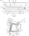
FIG. 4 is a perspective view of a turbine nozzle, according to an embodiment of the present disclosure. -
FIG. 5 is a perspective view of turbine shroud, according to an embodiment of the present disclosure. - Wherever possible, the same reference numbers will be used throughout the drawings to represent the same parts.
- Provided are exemplary apparatuses and gas turbine components, such as turbine nozzles and turbine shrouds. Embodiments of the present disclosure, in comparison to articles and methods not utilizing one or more features disclosed herein, decrease costs, decrease thermal strain, increase efficiency, improve elevated temperature performance, or a combination thereof.
- Referring to
FIG. 1 , in one embodiment anapparatus 100 includes afirst article 102, asecond article 104, afirst interface volume 106 disposed between and enclosed by thefirst article 102 and thesecond article 104, acooling fluid supply 108, and at least onecooling fluid channel 110 in fluid communication with thecooling fluid supply 108 and thefirst interface volume 106. Thefirst article 102 includes a first material composition. Thesecond article 104 includes a second material composition. The at least onecooling fluid channel 110 includes aheat exchange portion 112 disposed in at least one of the first article 102 (not shown) and the second article 104 (shown) downstream of thecooling fluid supply 108 and upstream of thefirst interface volume 106. In a further embodiment, the first material composition of thefirst article 102 includes a first thermal tolerance, and the second material composition of thesecond article 104 includes a second thermal tolerance greater than the first thermal tolerance. - In another embodiment, the
apparatus 100 further includes athird article 114 and asecond interface volume 116 disposed between and enclosed by thethird article 114 and thesecond article 104. Thethird article 114 includes a third material composition. The at least onecooling fluid channel 110 is upstream of and in fluid communication with thesecond interface volume 116, and theheat exchange portion 112 is upstream of thesecond interface volume 116. In a further embodiment, the third material composition of thethird article 114 includes a third thermal tolerance less than the second thermal tolerance. - The
apparatus 100 may further include asealing member 118 disposed between thefirst article 102 and thesecond article 104, wherein the sealingmember 118 encloses thefirst interface volume 106, a sealingmember 118 disposed between thesecond article 104 and thethird article 114, wherein the sealingmember 118 encloses thesecond interface volume 116, or both. The sealingmember 118 may form a hermetic seal or a non-hermetic seal. - The
first interface volume 106, thesecond interface volume 116, or both may be arranged and disposed to exhaust a cooling fluid from thecooling fluid supply 108 to anexternal environment 120. In one embodiment, wherein the sealingmember 118 forms a non-hermetic seal, a partially restricted flow of the cooling fluid may pass by the sealingmember 118 to exhaust to the outside environment. In another embodiment (not shown), theapparatus 100 may include a valve or restricted flow path independent of the sealingmember 118 through which a partially restricted flow of the cooling fluid may pass to exhaust to the outside environment. - Utilizing the cooling fluid to purge the
first interface volume 106, thesecond interface volume 116, or both, whether through a non-hermetic seal enclosed by sealingmember 118, a valve, or a restricted flow path independent of thesealing member 118, may reduce the amount of a cooling fluid diverted from acooling fluid supply 108, increasing efficiency of theapparatus 100 relative to a comparable apparatus using separate flows of the cooling fluid to thermally regulate theapparatus 100 and to purge thefirst interface volume 106, thesecond interface volume 116, or both. - The first material composition may be any suitable material, including, but not limited to, a metal, a nickel-based alloy, a superalloy, a nickel-based superalloy, an iron-based alloy, a steel alloy, a stainless steel alloy, a cobalt-based alloy, a titanium alloy, or a combination thereof. The second material composition may be any suitable material, including, but not limited to, a refractory metal, a superalloy, a nickel-based superalloy, a cobalt-based superalloy, a ceramic matrix composite, or a combination thereof. The ceramic matrix composite may include, but is not limited to, a ceramic material, an aluminum oxide-fiber-reinforced aluminum oxide (Ox/Ox), carbon-fiber-reinforced carbon (C/C), carbon-fiber-reinforced silicon carbide (C/SiC), and silicon-carbide-fiber-reinforced silicon carbide (SiC/SiC). In one embodiment, the first material composition is a metal and the second material composition is a ceramic matrix composite.
- In an embodiment having a
first article 102 and athird article 114, the third material composition may be the first material composition, or the third material composition may include a distinct material composition from the first material composition. As used herein, a "distinct" material composition indicates that the first material composition and the third material composition differ from one another by more than a difference in trace impurities such that the first material composition and the third material composition have material properties which are sufficiently different from one another to have a material affect at the operating conditions to which thearticle 100 is subjected. - Also in an embodiment having a
first article 102 and athird article 114, the third thermal tolerance may be the first thermal tolerance, or the third thermal tolerance may be distinct from the first thermal tolerance. - In one embodiment, the
apparatus 100 includes a reducedthermal gradient 122 between thefirst article 102 and thesecond article 104 relative to a comparable apparatus (not shown) in which a comparable at least one cooling fluid channel is isolated from a comparable interface volume. In an embodiment having afirst article 102 and athird article 114, theapparatus 100 may also include a reducedthermal gradient 122 between thesecond article 104 and thethird article 114 relative to the comparable apparatus. Without being bound by theory, it is believed that using a cooling fluid from acooling fluid supply 108 which passes through aheat exchange portion 112 of acooling fluid channel 110 prior to purging at least one of afirst interface volume 106 and asecond interface volume 116 may cool thesecond article 104, may elevate the temperature of at least one of thefirst interface volume 106 and thesecond interface volume 116, and may further elevate the temperature of at least one of thefirst article 102 and thethird article 114. - Referring to
FIGS. 1-3 , in one embodiment, theheat exchange portion 112 includes a firstheat exchange portion 124 and a secondheat exchange portion 126. Thefirst heat exchange 124 portion and the secondheat exchange portion 126 may be in parallel (as shown inFIG. 1 ) or in sequence (as shown inFIGS. 2-3 ). - Referring to
FIGS. 2 and3 , in one embodiment, theapparatus 100 includes a firstheat exchange portion 124 disposed in thefirst article 102 and a secondheat exchange portion 126 disposed in thesecond article 104. The firstheat exchange portion 124 may be downstream of the second heat exchange portion 126 (as shown inFIG. 2 ), or the firstheat exchange portion 124 may be upstream of the second heat exchange portion 126 (as shown inFIG. 3 ). Passing the cooling gas through the firstheat exchange portion 124 prior to passing the cooling gas through the secondheat exchange portion 126 may preheat the cooling gas and reduce any negative effects of thesecond article 104 being exposed to a cooling gas which is too cold, such as, but not limited to, local thermal stresses or delamination. Passing the cooling gas through the secondheat exchange portion 126 prior to passing the cooling gas through the firstheat exchange portion 124 may preheat the cooling gas and reduce cooling of thefirst article 104, thereby decreasing thethermal gradient 122. - Referring to
FIGS. 1-3 , theheat exchange portion 112 may include any suitable conformation, including, but not limited to, aserpentine configuration 128, a 1-pass configuration 200, a 1.5-pass configuration 202, a 2-pass configuration 300, or a combination thereof. As used herein, "serpentine configuration" is not limited to a configuration with sinuous curves, but may also include angled changes of direction. In one embodiment, the configuration of theheat exchange portion 112 is arranged and disposed to thermally regulate theapparatus 100 throughout the full extent of theapparatus 100. Thermal regulation may be a function of the flow of the cooling fluid, cross-sectional flow area within theheat exchange portion 112, surface area within theheat exchange portion 112, cooling fluid temperatures, and the velocity of the flow of the cooling fluid through the coolingfluid channel 110. These parameters may vary along the coolingfluid channel 110 to address variable thermal regulation conditions along the coolingfluid channel 110. In one embodiment, the coolingfluid channel 110 includes turbulators (not shown) such as pin banks, fins, bumps, dimples, and combinations thereof. As used herein, "turbulator" refers to a features which disrupts laminar flow. - The
apparatus 100 may be any suitable apparatus, including, but not limited to a turbine component. Suitable turbine components, may include, but are not limited to, nozzles (also known as vanes), shrouds, buckets (also known as blades), turbine cases, and combustor liners. - Referring to
FIG. 4 , in one embodiment theapparatus 100 is aturbine nozzle 400, thefirst article 102 is anendwall 402, and thesecond article 104 is afairing 404. In a further embodiment, theapparatus 100 includes athird article 114, which is also anendwall 402, wherein thefirst article 102 is anoutside wall 406 and the third article is aninside wall 408. Theheat exchange portion 112 may be disposed in aleading edge 410 of the fairing (shown), in a trailingedge 412 of the fairing (not shown), or between theleading edge 410 and the trailingedge 412 of the fairing (not shown). - Referring to
FIG. 5 , in another embodiment, theapparatus 100 is aturbine shroud 500, the first article is anouter shroud 502, and the second article is aninner shroud 504. - While the invention has been described with reference to a preferred embodiment, it will be understood by those skilled in the art that various changes may be made and equivalents may be substituted for elements thereof without departing from the scope of the invention. In addition, many modifications may be made to adapt a particular situation or material to the teachings of the invention without departing from the essential scope thereof. Therefore, it is intended that the invention not be limited to the particular embodiment disclosed as the best mode contemplated for carrying out this invention, but that the invention will include all embodiments falling within the scope of the appended claims.
- Various aspects and embodiments of the present invention are defined by the following numbered clauses:
- 1. An apparatus, comprising:
- a first article, the first article including a first material composition;
- a second article, the second article including a second material composition;
- a first interface volume disposed between and enclosed by the first article and the second article;
- a cooling fluid supply; and
- at least one cooling fluid channel in fluid communication with the cooling fluid supply and the first interface volume, the at least one cooling fluid channel including a heat exchange portion disposed in at least one of the first article and the second article downstream of the cooling fluid supply and upstream of the first interface volume.
- 2. The apparatus of clause 1, wherein the apparatus is a turbine component.
- 3. The apparatus of any preceding clause, wherein the turbine component is a nozzle, the first article is an endwall, and the second article is a fairing.
- 4. The apparatus of any preceding clause, wherein the heat exchange portion is disposed in a leading edge of the fairing.
- 5. The apparatus of any preceding clause, wherein the heat exchange portion is disposed in a trailing edge of the fairing.
- 6. The apparatus of any preceding clause, wherein the turbine component is a shroud, the first article is an outer shroud, and the second article is an inner shroud.
- 7. The apparatus of any preceding clause, further including:
- a third article, the third article including a third material composition; and
- a second interface volume disposed between and enclosed by the third article and the second article;
- wherein the at least one cooling fluid channel is upstream of and in fluid communication with the second interface volume, and the heat exchange portion is upstream of the second interface volume.
- 8. The apparatus of any preceding clause, wherein the apparatus is a turbine component, the turbine component is a nozzle, the first article is an outside wall, the second article is a fairing, and the third article is an inside wall.
- 9. The apparatus of any preceding clause, wherein the third material composition is the first material composition.
- 10. The apparatus of any preceding clause, wherein the first material composition is a metal and the second material composition is a ceramic matrix composite.
- 11. The apparatus of any preceding clause, including a reduced thermal gradient between the metal and the ceramic matrix composite relative to comparable apparatus in which a comparable at least one cooling fluid channel is isolated from a comparable interface volume.
- 12. The apparatus of any preceding clause, further including a sealing member disposed between the first article and the second article, the sealing member enclosing the first interface volume.
- 13. The apparatus of any preceding clause, wherein the sealing member forms a non-hermetic seal between the first article and the second article.
- 14. The apparatus of any preceding clause, wherein the first interface volume is arranged and disposed to exhaust a cooling fluid from the cooling fluid supply to an external environment.
- 15. The apparatus of any preceding clause, wherein the heat exchange portion includes a first heat exchange portion disposed in the first article and a second heat exchange portion disposed in the second article.
- 16. The apparatus of any preceding clause, wherein the first heat exchange portion is upstream of the second heat exchange portion.
- 17. The apparatus of any preceding clause, wherein the first heat exchange portion is downstream of the second heat exchange portion.
- 18. The apparatus of any preceding clause, wherein the heat exchange portion includes a configuration selected from the group consisting of a 1-pass configuration, a 1.5-pass configuration, a 2-pass configuration, and combinations thereof.
- 19. A turbine nozzle, comprising:
- an outside wall, the outside wall including a metal;
- a fairing, the fairing including a ceramic matrix composite;
- a first interface volume disposed between and enclosed by the outside wall and the fairing;
- an inside wall, the inside wall including a metal;
- a second interface volume disposed between and enclosed by the inside wall and the fairing;
- a cooling fluid supply; and
- at least one cooling fluid channel in fluid communication with the cooling fluid supply, the first interface volume, and the second interface volume, the at least one cooling fluid channel including a heat exchange portion disposed downstream of the cooling fluid supply and upstream of the first interface volume and the second interface volume.
- 20. A turbine shroud, comprising:
- an outer shroud, the outer shroud including a metal;
- an inner shroud, the inner shroud including a ceramic matrix composite;
- a first interface volume disposed between and enclosed by the outer shroud and the inner shroud;
- a cooling fluid supply; and
- at least one cooling fluid channel in fluid communication with the cooling fluid supply and the first interface volume, the at least one cooling fluid channel including a heat exchange portion disposed downstream of the cooling fluid supply and upstream of the first interface volume.
Claims (10)
- An apparatus (100), comprising:a first article (102), the first article (102) including a first material composition;a second article (104), the second article (104) including a second material composition;a first interface volume (106) disposed between and enclosed by the first article (102) and the second article (104);a cooling fluid supply (108); andat least one cooling fluid channel (110) in fluid communication with the cooling fluid supply (108) and the first interface volume (106), the at least one cooling fluid channel (110) including a heat exchange portion (112) disposed in at least one of the first article (102) and the second article (104) downstream of the cooling fluid supply (108) and upstream of the first interface volume (160).
- The apparatus (100) of claim 1, wherein the apparatus (100) is a turbine component.
- The apparatus (100) of claim 2, wherein the turbine component is a nozzle (400), the first article (102) is an endwall (402), and the second article (104) is a fairing (404).
- The apparatus (100) of claim 2, wherein the turbine component is a shroud (500), the first article (102) is an outer shroud (502), and the second article (104) is an inner shroud (504).
- The apparatus (100) of any of claims 1 to 4, further including:a third article (114), the third article (114) including a third material composition; anda second interface volume (116) disposed between and enclosed by the third article (114) and the second article (104),wherein the at least one cooling fluid channel (110) is upstream of and in fluid communication with the second interface volume (116), and the heat exchange portion (112) is upstream of the second interface volume (116).
- The apparatus (100) of claim 5, wherein the apparatus (100) is a turbine component, the turbine component is a nozzle (400), the first article (102) is an outside wall (406), the second article is a fairing (404), and the third article is an inside wall (408).
- The apparatus (100) of any preceding claim, wherein the first material composition is a metal and the second material composition is a ceramic matrix composite.
- The apparatus (100) of claim 7, including a reduced thermal gradient between the metal and the ceramic matrix composite relative to comparable apparatus in which a comparable at least one cooling fluid channel is isolated from a comparable interface volume.
- The apparatus (100) of any preceding claim, wherein the first interface volume (106) is arranged and disposed to exhaust a cooling fluid from the cooling fluid supply (108) to an external environment.
- The apparatus (100) of any preceding claim, wherein the heat exchange portion (112) includes a first heat exchange portion (124) disposed in the first article (102) and a second heat exchange portion (126) disposed in the second article (104).
Applications Claiming Priority (1)
| Application Number | Priority Date | Filing Date | Title |
|---|---|---|---|
| US15/080,201 US10550721B2 (en) | 2016-03-24 | 2016-03-24 | Apparatus, turbine nozzle and turbine shroud |
Publications (2)
| Publication Number | Publication Date |
|---|---|
| EP3222816A1 true EP3222816A1 (en) | 2017-09-27 |
| EP3222816B1 EP3222816B1 (en) | 2020-09-30 |
Family
ID=58358465
Family Applications (1)
| Application Number | Title | Priority Date | Filing Date |
|---|---|---|---|
| EP17161520.6A Active EP3222816B1 (en) | 2016-03-24 | 2017-03-17 | Apparatus, turbine nozzle and turbine shroud |
Country Status (3)
| Country | Link |
|---|---|
| US (1) | US10550721B2 (en) |
| EP (1) | EP3222816B1 (en) |
| JP (1) | JP7034594B2 (en) |
Cited By (1)
| Publication number | Priority date | Publication date | Assignee | Title |
|---|---|---|---|---|
| EP3232012B1 (en) * | 2016-04-01 | 2022-03-02 | General Electric Company | Turbine aparatus and method for redundant cooling of a turbine apparatus |
Families Citing this family (1)
| Publication number | Priority date | Publication date | Assignee | Title |
|---|---|---|---|---|
| US12091982B2 (en) * | 2022-06-10 | 2024-09-17 | Ge Infrastructure Technology Llc | Turbine component with heated structure to reduce thermal stress |
Citations (3)
| Publication number | Priority date | Publication date | Assignee | Title |
|---|---|---|---|---|
| US5690473A (en) * | 1992-08-25 | 1997-11-25 | General Electric Company | Turbine blade having transpiration strip cooling and method of manufacture |
| US20120237786A1 (en) * | 2011-03-17 | 2012-09-20 | Morrison Jay A | Process for making a wall with a porous element for component cooling |
| WO2015047698A1 (en) * | 2013-09-24 | 2015-04-02 | United Technologies Corporation | Bonded multi-piece gas turbine engine component |
Family Cites Families (17)
| Publication number | Priority date | Publication date | Assignee | Title |
|---|---|---|---|---|
| US4292008A (en) * | 1977-09-09 | 1981-09-29 | International Harvester Company | Gas turbine cooling systems |
| JPS6189906A (en) * | 1984-10-11 | 1986-05-08 | Central Res Inst Of Electric Power Ind | Cooling structure of ceramic/metal composite stator vanes |
| US5098257A (en) * | 1990-09-10 | 1992-03-24 | Westinghouse Electric Corp. | Apparatus and method for minimizing differential thermal expansion of gas turbine vane structures |
| JP3733575B2 (en) * | 1995-05-26 | 2006-01-11 | 石川島播磨重工業株式会社 | Support structure for ceramic guide vanes |
| JP4622074B2 (en) * | 2000-09-28 | 2011-02-02 | 株式会社Ihi | Turbine shroud cooling structure |
| US6758653B2 (en) * | 2002-09-09 | 2004-07-06 | Siemens Westinghouse Power Corporation | Ceramic matrix composite component for a gas turbine engine |
| US7217088B2 (en) * | 2005-02-02 | 2007-05-15 | Siemens Power Generation, Inc. | Cooling fluid preheating system for an airfoil in a turbine engine |
| US7448850B2 (en) * | 2006-04-07 | 2008-11-11 | General Electric Company | Closed loop, steam cooled turbine shroud |
| US8292580B2 (en) * | 2008-09-18 | 2012-10-23 | Siemens Energy, Inc. | CMC vane assembly apparatus and method |
| US8162598B2 (en) * | 2008-09-25 | 2012-04-24 | Siemens Energy, Inc. | Gas turbine sealing apparatus |
| US8075256B2 (en) * | 2008-09-25 | 2011-12-13 | Siemens Energy, Inc. | Ingestion resistant seal assembly |
| FR2954401B1 (en) | 2009-12-23 | 2012-03-23 | Turbomeca | METHOD FOR COOLING TURBINE STATORS AND COOLING SYSTEM FOR ITS IMPLEMENTATION |
| CH704252A1 (en) * | 2010-12-21 | 2012-06-29 | Alstom Technology Ltd | Built shovel arrangement for a gas turbine and method for operating such a blade arrangement. |
| US9670785B2 (en) * | 2012-04-19 | 2017-06-06 | General Electric Company | Cooling assembly for a gas turbine system |
| US20140064969A1 (en) * | 2012-08-29 | 2014-03-06 | Dmitriy A. Romanov | Blade outer air seal |
| US9634840B2 (en) * | 2013-07-23 | 2017-04-25 | Security Innovation Inc. | Digital signature technique |
| US10400627B2 (en) | 2015-03-31 | 2019-09-03 | General Electric Company | System for cooling a turbine engine |
-
2016
- 2016-03-24 US US15/080,201 patent/US10550721B2/en active Active
-
2017
- 2017-03-09 JP JP2017044484A patent/JP7034594B2/en active Active
- 2017-03-17 EP EP17161520.6A patent/EP3222816B1/en active Active
Patent Citations (3)
| Publication number | Priority date | Publication date | Assignee | Title |
|---|---|---|---|---|
| US5690473A (en) * | 1992-08-25 | 1997-11-25 | General Electric Company | Turbine blade having transpiration strip cooling and method of manufacture |
| US20120237786A1 (en) * | 2011-03-17 | 2012-09-20 | Morrison Jay A | Process for making a wall with a porous element for component cooling |
| WO2015047698A1 (en) * | 2013-09-24 | 2015-04-02 | United Technologies Corporation | Bonded multi-piece gas turbine engine component |
Cited By (1)
| Publication number | Priority date | Publication date | Assignee | Title |
|---|---|---|---|---|
| EP3232012B1 (en) * | 2016-04-01 | 2022-03-02 | General Electric Company | Turbine aparatus and method for redundant cooling of a turbine apparatus |
Also Published As
| Publication number | Publication date |
|---|---|
| EP3222816B1 (en) | 2020-09-30 |
| US10550721B2 (en) | 2020-02-04 |
| JP7034594B2 (en) | 2022-03-14 |
| JP2017172581A (en) | 2017-09-28 |
| US20170276021A1 (en) | 2017-09-28 |
Similar Documents
| Publication | Publication Date | Title |
|---|---|---|
| CN104564350B (en) | Arrangement for cooling components in a hot gas path of a gas turbine | |
| CN103161522B (en) | There is the component of microchannel cooling | |
| JP6006935B2 (en) | Airfoil part of turbomachine and cooling method thereof | |
| US8240987B2 (en) | Gas turbine engine systems involving baffle assemblies | |
| US8047787B1 (en) | Turbine blade with trailing edge root slot | |
| EP3214276B1 (en) | Thermal break in turbine nozzle and turbine shroud | |
| US20130094944A1 (en) | Bucket assembly for turbine system | |
| EP2657451A2 (en) | Turbine shroud cooling assembly for a gas turbine system | |
| US10830142B2 (en) | Combustor aft frame cooling | |
| CN102434224B (en) | Turbine airfoil and method for cooling a turbine airfoil | |
| US8628294B1 (en) | Turbine stator vane with purge air channel | |
| CN105408586B (en) | Turbo blade with aerofoil profile shape radiator | |
| EP3222816B1 (en) | Apparatus, turbine nozzle and turbine shroud | |
| US20140003937A1 (en) | Component and a method of cooling a component | |
| US8585350B1 (en) | Turbine vane with trailing edge extension | |
| US10775115B2 (en) | Thermal spray coating method and thermal spray coated article | |
| US8105014B2 (en) | Gas turbine engine article having columnar microstructure | |
| US10227878B2 (en) | Article and method of forming an article | |
| KR20200089739A (en) | Brazed in heat transfer features for cooled turbine components | |
| EP3232012B1 (en) | Turbine aparatus and method for redundant cooling of a turbine apparatus | |
| Talal et al. | Design and analysis of a gas turbine blade | |
| Hafner et al. | Apparatus, turbine nozzle and turbine shroud |
Legal Events
| Date | Code | Title | Description |
|---|---|---|---|
| AK | Designated contracting states |
Kind code of ref document: A1 Designated state(s): AL AT BE BG CH CY CZ DE DK EE ES FI FR GB GR HR HU IE IS IT LI LT LU LV MC MK MT NL NO PL PT RO RS SE SI SK SM TR |
|
| AX | Request for extension of the european patent |
Extension state: BA ME |
|
| PUAI | Public reference made under article 153(3) epc to a published international application that has entered the european phase |
Free format text: ORIGINAL CODE: 0009012 |
|
| STAA | Information on the status of an ep patent application or granted ep patent |
Free format text: STATUS: THE APPLICATION HAS BEEN PUBLISHED |
|
| STAA | Information on the status of an ep patent application or granted ep patent |
Free format text: STATUS: REQUEST FOR EXAMINATION WAS MADE |
|
| 17P | Request for examination filed |
Effective date: 20180327 |
|
| RBV | Designated contracting states (corrected) |
Designated state(s): AL AT BE BG CH CY CZ DE DK EE ES FI FR GB GR HR HU IE IS IT LI LT LU LV MC MK MT NL NO PL PT RO RS SE SI SK SM TR |
|
| STAA | Information on the status of an ep patent application or granted ep patent |
Free format text: STATUS: EXAMINATION IS IN PROGRESS |
|
| 17Q | First examination report despatched |
Effective date: 20181026 |
|
| GRAP | Despatch of communication of intention to grant a patent |
Free format text: ORIGINAL CODE: EPIDOSNIGR1 |
|
| STAA | Information on the status of an ep patent application or granted ep patent |
Free format text: STATUS: GRANT OF PATENT IS INTENDED |
|
| INTG | Intention to grant announced |
Effective date: 20191001 |
|
| GRAJ | Information related to disapproval of communication of intention to grant by the applicant or resumption of examination proceedings by the epo deleted |
Free format text: ORIGINAL CODE: EPIDOSDIGR1 |
|
| STAA | Information on the status of an ep patent application or granted ep patent |
Free format text: STATUS: EXAMINATION IS IN PROGRESS |
|
| INTC | Intention to grant announced (deleted) | ||
| GRAP | Despatch of communication of intention to grant a patent |
Free format text: ORIGINAL CODE: EPIDOSNIGR1 |
|
| STAA | Information on the status of an ep patent application or granted ep patent |
Free format text: STATUS: GRANT OF PATENT IS INTENDED |
|
| INTG | Intention to grant announced |
Effective date: 20200311 |
|
| GRAJ | Information related to disapproval of communication of intention to grant by the applicant or resumption of examination proceedings by the epo deleted |
Free format text: ORIGINAL CODE: EPIDOSDIGR1 |
|
| STAA | Information on the status of an ep patent application or granted ep patent |
Free format text: STATUS: EXAMINATION IS IN PROGRESS |
|
| INTC | Intention to grant announced (deleted) | ||
| GRAR | Information related to intention to grant a patent recorded |
Free format text: ORIGINAL CODE: EPIDOSNIGR71 |
|
| GRAS | Grant fee paid |
Free format text: ORIGINAL CODE: EPIDOSNIGR3 |
|
| STAA | Information on the status of an ep patent application or granted ep patent |
Free format text: STATUS: GRANT OF PATENT IS INTENDED |
|
| GRAA | (expected) grant |
Free format text: ORIGINAL CODE: 0009210 |
|
| STAA | Information on the status of an ep patent application or granted ep patent |
Free format text: STATUS: THE PATENT HAS BEEN GRANTED |
|
| INTG | Intention to grant announced |
Effective date: 20200820 |
|
| AK | Designated contracting states |
Kind code of ref document: B1 Designated state(s): AL AT BE BG CH CY CZ DE DK EE ES FI FR GB GR HR HU IE IS IT LI LT LU LV MC MK MT NL NO PL PT RO RS SE SI SK SM TR |
|
| REG | Reference to a national code |
Ref country code: CH Ref legal event code: EP Ref country code: GB Ref legal event code: FG4D |
|
| REG | Reference to a national code |
Ref country code: AT Ref legal event code: REF Ref document number: 1318984 Country of ref document: AT Kind code of ref document: T Effective date: 20201015 |
|
| REG | Reference to a national code |
Ref country code: DE Ref legal event code: R096 Ref document number: 602017024428 Country of ref document: DE |
|
| REG | Reference to a national code |
Ref country code: IE Ref legal event code: FG4D |
|
| PG25 | Lapsed in a contracting state [announced via postgrant information from national office to epo] |
Ref country code: FI Free format text: LAPSE BECAUSE OF FAILURE TO SUBMIT A TRANSLATION OF THE DESCRIPTION OR TO PAY THE FEE WITHIN THE PRESCRIBED TIME-LIMIT Effective date: 20200930 Ref country code: NO Free format text: LAPSE BECAUSE OF FAILURE TO SUBMIT A TRANSLATION OF THE DESCRIPTION OR TO PAY THE FEE WITHIN THE PRESCRIBED TIME-LIMIT Effective date: 20201230 Ref country code: GR Free format text: LAPSE BECAUSE OF FAILURE TO SUBMIT A TRANSLATION OF THE DESCRIPTION OR TO PAY THE FEE WITHIN THE PRESCRIBED TIME-LIMIT Effective date: 20201231 Ref country code: BG Free format text: LAPSE BECAUSE OF FAILURE TO SUBMIT A TRANSLATION OF THE DESCRIPTION OR TO PAY THE FEE WITHIN THE PRESCRIBED TIME-LIMIT Effective date: 20201230 Ref country code: SE Free format text: LAPSE BECAUSE OF FAILURE TO SUBMIT A TRANSLATION OF THE DESCRIPTION OR TO PAY THE FEE WITHIN THE PRESCRIBED TIME-LIMIT Effective date: 20200930 Ref country code: HR Free format text: LAPSE BECAUSE OF FAILURE TO SUBMIT A TRANSLATION OF THE DESCRIPTION OR TO PAY THE FEE WITHIN THE PRESCRIBED TIME-LIMIT Effective date: 20200930 |
|
| REG | Reference to a national code |
Ref country code: AT Ref legal event code: MK05 Ref document number: 1318984 Country of ref document: AT Kind code of ref document: T Effective date: 20200930 |
|
| PG25 | Lapsed in a contracting state [announced via postgrant information from national office to epo] |
Ref country code: LV Free format text: LAPSE BECAUSE OF FAILURE TO SUBMIT A TRANSLATION OF THE DESCRIPTION OR TO PAY THE FEE WITHIN THE PRESCRIBED TIME-LIMIT Effective date: 20200930 Ref country code: RS Free format text: LAPSE BECAUSE OF FAILURE TO SUBMIT A TRANSLATION OF THE DESCRIPTION OR TO PAY THE FEE WITHIN THE PRESCRIBED TIME-LIMIT Effective date: 20200930 |
|
| REG | Reference to a national code |
Ref country code: NL Ref legal event code: MP Effective date: 20200930 |
|
| REG | Reference to a national code |
Ref country code: LT Ref legal event code: MG4D |
|
| PG25 | Lapsed in a contracting state [announced via postgrant information from national office to epo] |
Ref country code: SM Free format text: LAPSE BECAUSE OF FAILURE TO SUBMIT A TRANSLATION OF THE DESCRIPTION OR TO PAY THE FEE WITHIN THE PRESCRIBED TIME-LIMIT Effective date: 20200930 Ref country code: EE Free format text: LAPSE BECAUSE OF FAILURE TO SUBMIT A TRANSLATION OF THE DESCRIPTION OR TO PAY THE FEE WITHIN THE PRESCRIBED TIME-LIMIT Effective date: 20200930 Ref country code: NL Free format text: LAPSE BECAUSE OF FAILURE TO SUBMIT A TRANSLATION OF THE DESCRIPTION OR TO PAY THE FEE WITHIN THE PRESCRIBED TIME-LIMIT Effective date: 20200930 Ref country code: LT Free format text: LAPSE BECAUSE OF FAILURE TO SUBMIT A TRANSLATION OF THE DESCRIPTION OR TO PAY THE FEE WITHIN THE PRESCRIBED TIME-LIMIT Effective date: 20200930 Ref country code: RO Free format text: LAPSE BECAUSE OF FAILURE TO SUBMIT A TRANSLATION OF THE DESCRIPTION OR TO PAY THE FEE WITHIN THE PRESCRIBED TIME-LIMIT Effective date: 20200930 Ref country code: PT Free format text: LAPSE BECAUSE OF FAILURE TO SUBMIT A TRANSLATION OF THE DESCRIPTION OR TO PAY THE FEE WITHIN THE PRESCRIBED TIME-LIMIT Effective date: 20210201 Ref country code: CZ Free format text: LAPSE BECAUSE OF FAILURE TO SUBMIT A TRANSLATION OF THE DESCRIPTION OR TO PAY THE FEE WITHIN THE PRESCRIBED TIME-LIMIT Effective date: 20200930 |
|
| PG25 | Lapsed in a contracting state [announced via postgrant information from national office to epo] |
Ref country code: PL Free format text: LAPSE BECAUSE OF FAILURE TO SUBMIT A TRANSLATION OF THE DESCRIPTION OR TO PAY THE FEE WITHIN THE PRESCRIBED TIME-LIMIT Effective date: 20200930 Ref country code: IS Free format text: LAPSE BECAUSE OF FAILURE TO SUBMIT A TRANSLATION OF THE DESCRIPTION OR TO PAY THE FEE WITHIN THE PRESCRIBED TIME-LIMIT Effective date: 20210130 Ref country code: ES Free format text: LAPSE BECAUSE OF FAILURE TO SUBMIT A TRANSLATION OF THE DESCRIPTION OR TO PAY THE FEE WITHIN THE PRESCRIBED TIME-LIMIT Effective date: 20200930 Ref country code: AL Free format text: LAPSE BECAUSE OF FAILURE TO SUBMIT A TRANSLATION OF THE DESCRIPTION OR TO PAY THE FEE WITHIN THE PRESCRIBED TIME-LIMIT Effective date: 20200930 Ref country code: AT Free format text: LAPSE BECAUSE OF FAILURE TO SUBMIT A TRANSLATION OF THE DESCRIPTION OR TO PAY THE FEE WITHIN THE PRESCRIBED TIME-LIMIT Effective date: 20200930 |
|
| PG25 | Lapsed in a contracting state [announced via postgrant information from national office to epo] |
Ref country code: SK Free format text: LAPSE BECAUSE OF FAILURE TO SUBMIT A TRANSLATION OF THE DESCRIPTION OR TO PAY THE FEE WITHIN THE PRESCRIBED TIME-LIMIT Effective date: 20200930 |
|
| REG | Reference to a national code |
Ref country code: DE Ref legal event code: R097 Ref document number: 602017024428 Country of ref document: DE |
|
| PLBE | No opposition filed within time limit |
Free format text: ORIGINAL CODE: 0009261 |
|
| STAA | Information on the status of an ep patent application or granted ep patent |
Free format text: STATUS: NO OPPOSITION FILED WITHIN TIME LIMIT |
|
| PG25 | Lapsed in a contracting state [announced via postgrant information from national office to epo] |
Ref country code: DK Free format text: LAPSE BECAUSE OF FAILURE TO SUBMIT A TRANSLATION OF THE DESCRIPTION OR TO PAY THE FEE WITHIN THE PRESCRIBED TIME-LIMIT Effective date: 20200930 |
|
| 26N | No opposition filed |
Effective date: 20210701 |
|
| PG25 | Lapsed in a contracting state [announced via postgrant information from national office to epo] |
Ref country code: IT Free format text: LAPSE BECAUSE OF FAILURE TO SUBMIT A TRANSLATION OF THE DESCRIPTION OR TO PAY THE FEE WITHIN THE PRESCRIBED TIME-LIMIT Effective date: 20200930 Ref country code: MC Free format text: LAPSE BECAUSE OF FAILURE TO SUBMIT A TRANSLATION OF THE DESCRIPTION OR TO PAY THE FEE WITHIN THE PRESCRIBED TIME-LIMIT Effective date: 20200930 |
|
| REG | Reference to a national code |
Ref country code: CH Ref legal event code: PL |
|
| PG25 | Lapsed in a contracting state [announced via postgrant information from national office to epo] |
Ref country code: SI Free format text: LAPSE BECAUSE OF FAILURE TO SUBMIT A TRANSLATION OF THE DESCRIPTION OR TO PAY THE FEE WITHIN THE PRESCRIBED TIME-LIMIT Effective date: 20200930 |
|
| REG | Reference to a national code |
Ref country code: BE Ref legal event code: MM Effective date: 20210331 |
|
| PG25 | Lapsed in a contracting state [announced via postgrant information from national office to epo] |
Ref country code: LI Free format text: LAPSE BECAUSE OF NON-PAYMENT OF DUE FEES Effective date: 20210331 Ref country code: LU Free format text: LAPSE BECAUSE OF NON-PAYMENT OF DUE FEES Effective date: 20210317 Ref country code: CH Free format text: LAPSE BECAUSE OF NON-PAYMENT OF DUE FEES Effective date: 20210331 Ref country code: IE Free format text: LAPSE BECAUSE OF NON-PAYMENT OF DUE FEES Effective date: 20210317 Ref country code: FR Free format text: LAPSE BECAUSE OF NON-PAYMENT OF DUE FEES Effective date: 20210331 |
|
| PG25 | Lapsed in a contracting state [announced via postgrant information from national office to epo] |
Ref country code: IS Free format text: LAPSE BECAUSE OF FAILURE TO SUBMIT A TRANSLATION OF THE DESCRIPTION OR TO PAY THE FEE WITHIN THE PRESCRIBED TIME-LIMIT Effective date: 20210130 |
|
| PG25 | Lapsed in a contracting state [announced via postgrant information from national office to epo] |
Ref country code: BE Free format text: LAPSE BECAUSE OF NON-PAYMENT OF DUE FEES Effective date: 20210331 |
|
| PG25 | Lapsed in a contracting state [announced via postgrant information from national office to epo] |
Ref country code: HU Free format text: LAPSE BECAUSE OF FAILURE TO SUBMIT A TRANSLATION OF THE DESCRIPTION OR TO PAY THE FEE WITHIN THE PRESCRIBED TIME-LIMIT; INVALID AB INITIO Effective date: 20170317 |
|
| PG25 | Lapsed in a contracting state [announced via postgrant information from national office to epo] |
Ref country code: CY Free format text: LAPSE BECAUSE OF FAILURE TO SUBMIT A TRANSLATION OF THE DESCRIPTION OR TO PAY THE FEE WITHIN THE PRESCRIBED TIME-LIMIT Effective date: 20200930 |
|
| REG | Reference to a national code |
Ref country code: DE Ref legal event code: R081 Ref document number: 602017024428 Country of ref document: DE Owner name: GENERAL ELECTRIC TECHNOLOGY GMBH, CH Free format text: FORMER OWNER: GENERAL ELECTRIC COMPANY, SCHENECTADY, NY, US |
|
| REG | Reference to a national code |
Ref country code: GB Ref legal event code: 732E Free format text: REGISTERED BETWEEN 20240222 AND 20240228 |
|
| PG25 | Lapsed in a contracting state [announced via postgrant information from national office to epo] |
Ref country code: MK Free format text: LAPSE BECAUSE OF FAILURE TO SUBMIT A TRANSLATION OF THE DESCRIPTION OR TO PAY THE FEE WITHIN THE PRESCRIBED TIME-LIMIT Effective date: 20200930 |
|
| PG25 | Lapsed in a contracting state [announced via postgrant information from national office to epo] |
Ref country code: MT Free format text: LAPSE BECAUSE OF FAILURE TO SUBMIT A TRANSLATION OF THE DESCRIPTION OR TO PAY THE FEE WITHIN THE PRESCRIBED TIME-LIMIT Effective date: 20200930 |
|
| PG25 | Lapsed in a contracting state [announced via postgrant information from national office to epo] |
Ref country code: TR Free format text: LAPSE BECAUSE OF FAILURE TO SUBMIT A TRANSLATION OF THE DESCRIPTION OR TO PAY THE FEE WITHIN THE PRESCRIBED TIME-LIMIT Effective date: 20200930 |
|
| PGFP | Annual fee paid to national office [announced via postgrant information from national office to epo] |
Ref country code: GB Payment date: 20260219 Year of fee payment: 10 |
|
| PGFP | Annual fee paid to national office [announced via postgrant information from national office to epo] |
Ref country code: DE Payment date: 20260219 Year of fee payment: 10 |