EP3225920A1 - Hotte aspirante - Google Patents
Hotte aspirante Download PDFInfo
- Publication number
- EP3225920A1 EP3225920A1 EP17158174.7A EP17158174A EP3225920A1 EP 3225920 A1 EP3225920 A1 EP 3225920A1 EP 17158174 A EP17158174 A EP 17158174A EP 3225920 A1 EP3225920 A1 EP 3225920A1
- Authority
- EP
- European Patent Office
- Prior art keywords
- protective grid
- air
- extractor
- protective
- extractor hood
- Prior art date
- Legal status (The legal status is an assumption and is not a legal conclusion. Google has not performed a legal analysis and makes no representation as to the accuracy of the status listed.)
- Withdrawn
Links
Images


Classifications
-
- F—MECHANICAL ENGINEERING; LIGHTING; HEATING; WEAPONS; BLASTING
- F24—HEATING; RANGES; VENTILATING
- F24C—DOMESTIC STOVES OR RANGES ; DETAILS OF DOMESTIC STOVES OR RANGES, OF GENERAL APPLICATION
- F24C15/00—Details
- F24C15/20—Removing cooking fumes
-
- F—MECHANICAL ENGINEERING; LIGHTING; HEATING; WEAPONS; BLASTING
- F24—HEATING; RANGES; VENTILATING
- F24C—DOMESTIC STOVES OR RANGES ; DETAILS OF DOMESTIC STOVES OR RANGES, OF GENERAL APPLICATION
- F24C15/00—Details
- F24C15/20—Removing cooking fumes
- F24C15/2035—Arrangement or mounting of filters
-
- F—MECHANICAL ENGINEERING; LIGHTING; HEATING; WEAPONS; BLASTING
- F24—HEATING; RANGES; VENTILATING
- F24C—DOMESTIC STOVES OR RANGES ; DETAILS OF DOMESTIC STOVES OR RANGES, OF GENERAL APPLICATION
- F24C15/00—Details
- F24C15/20—Removing cooking fumes
- F24C15/2071—Removing cooking fumes mounting of cooking hood
Definitions
- the present invention relates to an extractor hood.
- extractor hoods required for sucking the air to be cleaned vacuum is generated by a blower.
- the blower is usually operated electrically and has a rotating fan wheel.
- a protective grid is usually provided in the hood.
- Such a protective grid is for example in the DE 10 2007 021 318 A1 described.
- a disadvantage of this known protective grid is that this reduces the achievable with the blower delivery volume.
- Object of the present invention is therefore to provide a cooker hood, in which a reliable protection of the user is ensured at the same time optimal operation of the hood.
- the invention is based on the finding that this object can be achieved by the protective grid influences the air flow to the fan so that it reaches the fan with the least possible loss or without loss.
- an extractor hood comprising a fume hood housing with a suction port, a blower with at least one air inlet opening and a protective grid.
- the extractor hood is characterized in that the protective grid is attached to the extractor housing, the protective grille is secured to the at least one air inlet opening vertically in the suction opening, the protective grille completely covers the suction opening and the protective grid has at least one air guide element between the inlet side of the protective grid and the exit side of the protective grid is at least partially curved.
- the extractor hood As an extractor hood according to the invention a device for sucking and cleaning of contaminated air understood, in particular understood by fumes and vapors that arise during cooking.
- the extractor hood includes a cooker hood housing with a suction opening, through which the air to be cleaned is sucked into the interior of the extractor hood.
- a fan is arranged, which can represent, for example, a one-sided or two-sided radial fan.
- the fan consists of one or more fans, each having at least one fan and a fan housing. At least one air inlet opening is provided in the fan housing.
- the blower housing has an air outlet opening which, in the case of a radial blower designed as a spiral blower, lies in particular on an air outlet duct and is perpendicular to the air inlet opening or openings.
- the at least one air inlet opening preferably represents a circular opening.
- the extractor hood according to the invention comprises a protective grid.
- the protective grid is attached to the extractor housing.
- advantages over engagement protectors provided directly on the blower can be provided. Namely, such devices have significant disadvantages. Thus, these always lead to a performance deterioration, since the inflow of air is disturbed directly at the fan.
- the protective grid is attached to the extractor housing so that it completely covers the intake opening of the extractor housing.
- an arrangement of the protective grid in the suction port is referred to, in which the edges of the protective grid are offset at the edges of the suction port or to the edges of the suction port to the outside.
- the surface formed by the protective grille completely covers the suction opening. Also by this design and arrangement of the protective grille there are significant advantages over safety devices provided on the fan, since the interior of the device is not accessible in this embodiment. This means that no separate measures have to be taken to secure cables, for example. In addition, at This embodiment also no sheet metal edges accessible to the user of the hood, which could injure and disturb the user when cleaning the hood.
- the protective grid is in the extractor hood according to the invention perpendicular to the at least one air inlet opening of the blower.
- the blower is a spiral blower
- part of the outer periphery of the spiral casing may face the protective grid and the air intake opening (s) provided in the one or more sides are perpendicular to the surface of the protective grid.
- the air exiting the protective grille flows at least partially parallel to the surface of the air inlet opening.
- a protective grid is understood to be a component in which grid elements extend at least in one direction and in which passage openings for air are formed between the grid elements.
- the protective grid has at least one air guiding element.
- the air guide element forms a grid element of the protective grid and is fixedly mounted in the protective grid.
- a plurality of air guide elements are provided.
- An air guiding element is an element which at least partially alters the direction of the air flow passing through the protective grille.
- the at least one air-guiding element is curved at least in regions between the inlet side of the protective grid and the outlet side of the protective grid.
- the entry side of the protective grille is the side facing outwards in the installed state of the protective grille on the extractor housing and via which the air flow drawn in enters.
- the exit side is the side of the protective grid which faces the interior of the extractor housing in the assembled state of the protective grid on the extractor housing and via which the aspirated air stream exits from the protective grid.
- the at least one air guide element is shaped so that it is curved between the inlet side and the outlet side.
- the distance between the inlet side and the outlet side is also referred to as the thickness or height of the protective grid.
- the radius of curvature of the air guide element can be constant between the inlet side and the outlet side, that is to say over the height of the protective grid. However, it is also within the scope of the invention that the Radius of curvature changes over the height of the protective grid, that varies over the height.
- the at least one air guiding element preferably represents a lamella.
- the lamella in this case has a curved cross section.
- a lamella is a strip of material which has a longitudinal extent, that is to say has a larger dimension in one direction than in the other two directions.
- the lamella or lamellae are preferably arranged in the protective grid in such a way that their longitudinal extension lies in the horizontal direction in the mounted state of the protective grid in the extractor hood.
- the air flow passing through the protective grid can be changed in its main flow direction so that the outgoing air flow is inclined to the surface of the protective grid.
- this change in direction which is effected in the protective grid, it is possible to direct the exiting air flow as a directed air flow to the fan.
- the air flow in the protective grid used in the invention can be output so that it can be sucked with minimal losses to the fan.
- the performance of the hood is not impaired and ideally even improved.
- the delivery volume and the efficiency are referred to as the performance of the extractor hood, which are at least not worsened or, preferably, even improved.
- the reduction of noise to the performance of the hood can be expected.
- the at least one air guiding element is oriented and shaped in such a way that a directed air flow is emitted through the protective grid, the main flow direction of which is offset from the center of the air inlet opening of the blower.
- Directed air flow is an air flow which has a main flow direction in which the largest volume part of the air flow flows.
- the main flow direction extends in this preferred embodiment offset to the center of the air inlet opening of the blower.
- a main flow direction is designated, which is aligned at the air inlet opening at least in regions such that it does not run at the center of the air inlet opening at the air inlet opening.
- the at least one air guiding element is shaped and aligned such that the main flow direction is inclined downwards towards the center of the air inlet opening.
- the fan and in particular the fan wheel is arranged in the fan housing.
- the air inlet opening is here aligned with the fan.
- the axis of the fan wheel is preferably located in the center of the air inlet opening.
- the fan is preferably rotated or rotated so that the fan blades rotate in the direction that is directed to the protective grid. If the protective grille is in a vertical plan view of the air inlet opening, for example on the left side of the fan, the fan is preferably rotated counterclockwise. If the protective grille is in a vertical plan view of the air inlet opening, for example on the right side of the fan, the fan is preferably rotated in a clockwise direction. In either case, an airflow whose main flow direction is parallel to the air inlet opening and down to the center point, when entering the fan, will strike in the direction of the fan wheels in which they are moving.
- the main flow direction of the air flow from the protective grid can be adjusted by the protective grid so that the main flow direction, for example, in a vertical plan view of the air inlet opening tangent to the surface of the air inlet opening or the main flow direction intersects the circular surface of the air inlet opening in vertical plan view of the air inlet opening as a secant.
- the airflow can be brought in a direction corresponding to the main suction direction of the blower Turbulences that lead to a reduction of the delivery volume are prevented.
- the main suction direction of the blower is determined by the direction of movement of the fan wheel.
- a plurality of air guiding elements are arranged parallel to one another in the protective grid. By having the air directing elements aligned in parallel, uniform entry of air into the protective grid across the surface of the protective grille can be ensured.
- the protective grid on several air guide elements and all air guide elements of the protective grid have the same shape. Also by this configuration, a uniform flow is effected.
- the protective grid has at least one reinforcing strut.
- the at least one reinforcing strut is arranged twisted in the protective grid relative to the at least one air guiding element.
- a reinforcing strut is referred to as being twisted, the longitudinal extent of which is at an angle to the longitudinal extent of the at least one air guiding element in a vertical plan view on the inlet side or outlet side of the protective grid which is greater than zero and not equal to 180 °.
- the longitudinal extension of the at least one reinforcing strut is perpendicular to the longitudinal extension of the at least one air guide element.
- the stability of the protective grid can be improved.
- a bending of the or the air guide elements can be reliably prevented.
- the distance between air guide elements can be fixed by the reinforcing struts.
- the at least one reinforcing strut has a lower height than the at least one air guiding element.
- the at least one reinforcing strut is arranged on the outlet side of the protective grid. In this case, the reinforcing strut extends from the outlet side in the direction of the inlet side of the protective grid.
- the protective grid has at least two air guide elements and the air guide elements cover the surface of the protective grid in a vertical plan view of the entry side of the protective grid.
- the air guiding elements preferably cover the surface of the protective grid in the horizontal direction.
- the protective grid is secured by means of latching connection and / or clamping connection to the extractor housing.
- latching connection and / or clamping connection to the extractor housing.
- the protective grid has at least one fastening device for fastening at least one filter element.
- the structure of the extractor hood is further simplified.
- the performance of the hood can be improved as a result, since separate fastening devices for filter elements, which would lead to a further obstruction of the air flow, can be prevented.
- the suction opening and the protective grid are aligned in the extractor housing in a direction inclined to the horizontal, the fan is in the horizontal direction behind the suction port and the at least one air guide is from the inlet side to the outlet side of the protective grid in the state attached to the suction port curved from an upward inclined direction in a downward inclined direction.
- the embodiment of the extractor hood, in which the suction opening is oriented in a direction pivoted to the horizontal direction, is also referred to as an oblique hood or inclined hood.
- the vapor which usually rises vertically upwards, flows from below to the inclined intake opening.
- the protective grid is aligned in a direction inclined to the horizontal direction and preferably parallel to the suction port is located, the Wrasen or cleaned by a possibly provided filter element air and the protective grid to flow substantially vertically from below. Due to the curvature of the air guide elements, a vertical impact on the air guide element is prevented when the air impinges on the inlet side of the protective grille. In addition, due to the further curvature of the air guide element, a deflection of the air flow in a downwardly inclined direction. The thus emerging air flow may therefore be directed to the lower region of a blower arranged behind the suction opening.
- FIG. 1 is a schematic front view of an embodiment of the extractor hood 1 according to the invention shown.
- the extractor hood 1 comprises a fume hood housing 10 and a vapor shield 11.
- a suction opening 17 is introduced.
- a baffle plate 12 which is arranged in the operation of the extractor hood 1 in front of the suction opening 17, folded upwards.
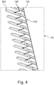
- a suction port 14 is introduced in the extractor housing 10 in the suction opening 14, a protective grid 15 is introduced. From the protective grid 15, the inlet side 153 can be seen in the illustrated embodiment.
- the inlet side 153 is formed by the longitudinal edges of extending in the width direction of the hood 1 air guide elements 150, which are also referred to below as fins.
- FIG. 2 is a schematic sectional view of an embodiment of the hood 1 shown. Also in this embodiment, the extractor hood 1 is formed by a fume hood housing 10 and a Wrasentran 11. The vapor shield 11 is inclined in the illustrated embodiment from the horizontal upwards.
- a fan 16 is arranged in the extractor housing 10.
- the blower 16 has an air inlet port 160, which is a circular opening, and an air outlet port 161 formed on the housing of the blower 16. Inside the blower housing a fan (not visible) is arranged.
- a suction port 14 is formed, which is offset to the suction opening 17 of the vapor shield 11 to the rear.
- baffle plate 12 is provided in front of the vapor shield 11 and in particular in front of the suction opening 17 at a distance from the vapor shield 11 .
- a baffle plate 12 is provided in front of the vapor shield 11 and in particular in front of the suction opening 17 at a distance from the vapor shield 11 .
- a grease filter 13 is arranged in front of the suction opening 14 in the extractor housing 10. Behind the grease filter 13 and in the suction port 14, a protective grid 15 is introduced.
- the grease filter 13 may, for example, connected to the protective grid 15, that is to be attached to this.
- the protective grid 15 is attached to the extractor housing 10 and has a size which completely covers the intake opening 14.
- the blower 16 constitutes a spiral blower.
- the blower 16 is arranged in the extractor housing 10 such that the air inlet opening 160 is perpendicular to the protective grid 15.
- the fan 16 is arranged in the horizontal direction behind the suction opening in the extractor housing 10.
- the protective grid 15 consists of a plurality of air guide elements 150 whose longitudinal extent lies in the horizontal.
- the air guide elements 150 each have a shape curved over the height thereof.
- the height of the protective grid 15, the dimension of the protective grid 15 is referred to, which is perpendicular to the surface of the protective grid 15.
- the vertical distance between the inlet side 153 and the outlet side 154 of the protective grid 15 is referred to as height.
- FIG. 2 are schematically indicated the currents that are achieved with the embodiment of the hood 1.
- the fumes and vapor After the fumes and vapor have flowed through the grease filter 13, they come as purified air in the inlet side 153 of the protective grid 15 and are output on the outlet side 154 of the protective grid 15.
- Due to the curvature of the air guide elements 150 the initially vertically upward flow of steam in the extractor housing is present as a slightly upward air flow or horizontal air flow.
- the main flow direction H of the air flow is in FIG. 2 shown schematically.
- the main flow direction H of the air flow is directed to the lower region of the air inlet opening 160 of the blower 16, that is, the main flow direction H extends in a vertical plan view of the air inlet opening 160 to the center of the air inlet opening 160 downwardly offset.
- the fan (not shown) of the blower 16 is in the in FIG. 2 shown embodiment rotated counterclockwise.
- a vortex-shaped suction is formed via the fan wheel (not shown) provided therein. Due to the curvature of the air guiding elements 150, the air drawn in by the protective grille 15 is oriented so that it is tangential or secant hits the suction and thus forms a vortex. The air is discharged from the extractor hood 1 after passing through the fan wheel through the air outlet channel 161.
- the protective grid 15 has this transversely extending air guide elements 150, a plurality of reinforcing struts 151.
- the reinforcing struts 151 extend perpendicular to the longitudinal extension of the air guide elements 150 and are therefore also referred to as vertical struts. In the illustrated embodiment, the reinforcing struts 151 protrude beyond the rear longitudinal edges of the spoiler elements 150.
- the connection is produced by sliding hooks 101 and latching hook 100 on the extractor housing 11, which engage in corresponding openings on the protective grid 15.
- the air guide elements 150 are held on the reinforcing struts 151.
- the height of the reinforcing struts 151 is smaller than the height of the Luftleitelemetente 150.
- an extractor hood in which a protective system is implemented by a protective grid, which prevents the customer touches rotating parts such as the fan and live parts.
- This protective grille which can also be referred to as anti-tampering, can cause as little or no loss in performance as possible, despite interference with the air duct of the extractor hood.
- the guard will even achieve improved performance.
- additional functions such as the filter holder or filter holder, for example, of grease and / or circulating air filters on the protective grid and a filter seal are possible.
- the hood also cleanability is improved and created a privacy through the guard.
- the shape of the air-guiding elements that is to say the lamella shape
- the slats must meet several parts of conflicting requirements. Basically, these have to fulfill all safety requirements of VDE, which demands a high stability and fixed connection to the housing.
- the protective grid must also prevent the user from reaching into the rotating fan wheel or to live components. For this purpose, usually a high material usage and small distances between the slats are necessary. However, the small clearance between the blades and the high material usage increase the obstruction area in the intake area, which leads to a deterioration in the performance values (delivery volume, noise, efficiency).
- the air guide elements that is to say slats
- the fins of the protective grid are preferably designed so that the properties of the fan are optimally supported, that is, the sucked air is placed in a twist and passes lossless in the fan.
- the protective grid can preferably be mounted without screws. This is implemented, for example, via a sliding latching closure, in which, for example, sliding lugs and / or latching hooks are used.
- a good privacy in the cooker hood can also be supplied through the protective grille and enhances the visual appearance of the cooker hood.
- cables will be covered so that they are not visible from the outside. This requirement is again in conflict with the barrier area and has been implemented taking into account the performance values to be achieved.
- the invention thus has a number of advantages.
- the user is protected against mechanical and electrical hazards. Simple cleaning of the protective grid is possible.
- the mounting of the protective grille can be screwless.
- a performance improvement by the geometry of the air guide elements which can also be referred to as Leitgeometrie achieved, while maintaining or improving the delivery volume and efficiency and minimizes noise, for example.
- the interior of the extractor hood preferably can not be accessible, so that the protective grid also serves as a privacy screen for the interior.
Landscapes
- Engineering & Computer Science (AREA)
- Chemical & Material Sciences (AREA)
- Combustion & Propulsion (AREA)
- Mechanical Engineering (AREA)
- General Engineering & Computer Science (AREA)
- Ventilation (AREA)
Applications Claiming Priority (1)
| Application Number | Priority Date | Filing Date | Title |
|---|---|---|---|
| DE102016205373.6A DE102016205373A1 (de) | 2016-03-31 | 2016-03-31 | Dunstabzugshaube |
Publications (1)
| Publication Number | Publication Date |
|---|---|
| EP3225920A1 true EP3225920A1 (fr) | 2017-10-04 |
Family
ID=58185425
Family Applications (1)
| Application Number | Title | Priority Date | Filing Date |
|---|---|---|---|
| EP17158174.7A Withdrawn EP3225920A1 (fr) | 2016-03-31 | 2017-02-27 | Hotte aspirante |
Country Status (2)
| Country | Link |
|---|---|
| EP (1) | EP3225920A1 (fr) |
| DE (1) | DE102016205373A1 (fr) |
Cited By (4)
| Publication number | Priority date | Publication date | Assignee | Title |
|---|---|---|---|---|
| CN108613233A (zh) * | 2018-06-08 | 2018-10-02 | 天津大学 | 一种旋转纤维板油烟净化装置 |
| CN109631114A (zh) * | 2018-12-31 | 2019-04-16 | 佛山市云米电器科技有限公司 | 一种可调整进风角度的烟机外壳 |
| DE202019103290U1 (de) | 2019-06-12 | 2019-06-18 | BSH Hausgeräte GmbH | Dunstabzugshaube mit Schutzelement |
| EP4180725A1 (fr) * | 2021-11-10 | 2023-05-17 | Berbel Ablufttechnik GmbH | Hotte aspirante |
Citations (7)
| Publication number | Priority date | Publication date | Assignee | Title |
|---|---|---|---|---|
| DE8303643U1 (de) * | 1983-02-10 | 1983-08-11 | Homeier, Max, 8411 Viehhausen | Nischenluefter |
| JPS6423047A (en) * | 1987-07-17 | 1989-01-25 | Daiichi Home Kk | Exhaust suction opening for forced ventilating device for cooking |
| JPH03207925A (ja) * | 1990-01-08 | 1991-09-11 | Matsushita Electric Ind Co Ltd | 排煙装置 |
| DE10052233A1 (de) * | 2000-10-21 | 2002-05-02 | Max Homeier | Dunstabzugshaube |
| EP1522793A1 (fr) * | 2003-10-08 | 2005-04-13 | bulthaup GmbH & Co KG | Hotte d'aspiration de fumée |
| DE102007021318A1 (de) | 2007-05-07 | 2008-11-13 | BSH Bosch und Siemens Hausgeräte GmbH | Dunstabzugsgehäuse und Dunstabzugshaube |
| DE102009055077A1 (de) * | 2009-12-21 | 2011-06-22 | BSH Bosch und Siemens Hausgeräte GmbH, 81739 | Lüfterkasten für Dunstabzugshaube |
-
2016
- 2016-03-31 DE DE102016205373.6A patent/DE102016205373A1/de not_active Ceased
-
2017
- 2017-02-27 EP EP17158174.7A patent/EP3225920A1/fr not_active Withdrawn
Patent Citations (7)
| Publication number | Priority date | Publication date | Assignee | Title |
|---|---|---|---|---|
| DE8303643U1 (de) * | 1983-02-10 | 1983-08-11 | Homeier, Max, 8411 Viehhausen | Nischenluefter |
| JPS6423047A (en) * | 1987-07-17 | 1989-01-25 | Daiichi Home Kk | Exhaust suction opening for forced ventilating device for cooking |
| JPH03207925A (ja) * | 1990-01-08 | 1991-09-11 | Matsushita Electric Ind Co Ltd | 排煙装置 |
| DE10052233A1 (de) * | 2000-10-21 | 2002-05-02 | Max Homeier | Dunstabzugshaube |
| EP1522793A1 (fr) * | 2003-10-08 | 2005-04-13 | bulthaup GmbH & Co KG | Hotte d'aspiration de fumée |
| DE102007021318A1 (de) | 2007-05-07 | 2008-11-13 | BSH Bosch und Siemens Hausgeräte GmbH | Dunstabzugsgehäuse und Dunstabzugshaube |
| DE102009055077A1 (de) * | 2009-12-21 | 2011-06-22 | BSH Bosch und Siemens Hausgeräte GmbH, 81739 | Lüfterkasten für Dunstabzugshaube |
Cited By (5)
| Publication number | Priority date | Publication date | Assignee | Title |
|---|---|---|---|---|
| CN108613233A (zh) * | 2018-06-08 | 2018-10-02 | 天津大学 | 一种旋转纤维板油烟净化装置 |
| CN108613233B (zh) * | 2018-06-08 | 2024-03-22 | 天津大学 | 一种旋转纤维板油烟净化装置 |
| CN109631114A (zh) * | 2018-12-31 | 2019-04-16 | 佛山市云米电器科技有限公司 | 一种可调整进风角度的烟机外壳 |
| DE202019103290U1 (de) | 2019-06-12 | 2019-06-18 | BSH Hausgeräte GmbH | Dunstabzugshaube mit Schutzelement |
| EP4180725A1 (fr) * | 2021-11-10 | 2023-05-17 | Berbel Ablufttechnik GmbH | Hotte aspirante |
Also Published As
| Publication number | Publication date |
|---|---|
| DE102016205373A1 (de) | 2017-10-05 |
Similar Documents
| Publication | Publication Date | Title |
|---|---|---|
| EP0118570B1 (fr) | Hotte d'évacuation à circulation d'air | |
| DE19753373A1 (de) | Axiallüfter-Gehäuse | |
| EP3225920A1 (fr) | Hotte aspirante | |
| EP3504482B2 (fr) | Appareil combiné comprenant une plaque de cuisson et un dispositif d'aspiration de vapeurs | |
| EP2397775A2 (fr) | Dispositif d'aspiration | |
| EP3232127B1 (fr) | Hotte aspirante comprenant une grille d'évacuation | |
| DE3120569A1 (de) | "kuechendunstabzugshaube" | |
| DE202015003637U1 (de) | Elektrischer Schrank | |
| EP3710755B1 (fr) | Dispositif d'aspiration de fumées pour une plaque de cuisson et meuble de cuisine avec dispositif d'aspiration de fumées | |
| DE102008053145A1 (de) | Strömungsleitvorrichtung für ein Gargerät | |
| DE102017216456A1 (de) | Lüftungsvorrichtung für Kochfeld und Kochfeld mit Lüftungsvorrichtung | |
| DE102019109401B4 (de) | Lüftereinrichtung zum Ansaugen und Ableiten von Wrasen nach unterhalb eines Kochfeldes und Kochfeld | |
| EP0726424A2 (fr) | Hotte aspiratrice de buée | |
| DE202012104696U1 (de) | Dunstabzugshaube | |
| EP3421806B1 (fr) | Ventilateur | |
| WO2011047944A1 (fr) | Elément-filtre pour un four | |
| DE102019220295A1 (de) | Erzeugung eines Luftvorhangs zur Verbesserung des Wraseneinzugs bei Dunstabzugshauben | |
| EP2629024B1 (fr) | Hotte avec aspiration améliorée | |
| DE102017131168A1 (de) | Dunstabzugshaube mit rundem Einströmungsbereich in schräger Führungsfläche | |
| WO2021254741A1 (fr) | Appareil d'extraction, et agencement de cuisine doté d'une cuisinière et d'un appareil d'extraction | |
| DE202019103290U1 (de) | Dunstabzugshaube mit Schutzelement | |
| DE2407796A1 (de) | Durchzugbelueftete elektrische maschine | |
| DE102017123759A1 (de) | "Ausblaseinrichtung" | |
| EP4644783A1 (fr) | Déflecteur de air circulant pour hotte aspirante et hotte aspirante | |
| DE102014108252A1 (de) | Filtereinrichtung |
Legal Events
| Date | Code | Title | Description |
|---|---|---|---|
| PUAI | Public reference made under article 153(3) epc to a published international application that has entered the european phase |
Free format text: ORIGINAL CODE: 0009012 |
|
| STAA | Information on the status of an ep patent application or granted ep patent |
Free format text: STATUS: THE APPLICATION HAS BEEN PUBLISHED |
|
| AK | Designated contracting states |
Kind code of ref document: A1 Designated state(s): AL AT BE BG CH CY CZ DE DK EE ES FI FR GB GR HR HU IE IS IT LI LT LU LV MC MK MT NL NO PL PT RO RS SE SI SK SM TR |
|
| AX | Request for extension of the european patent |
Extension state: BA ME |
|
| STAA | Information on the status of an ep patent application or granted ep patent |
Free format text: STATUS: REQUEST FOR EXAMINATION WAS MADE |
|
| 17P | Request for examination filed |
Effective date: 20180404 |
|
| RBV | Designated contracting states (corrected) |
Designated state(s): AL AT BE BG CH CY CZ DE DK EE ES FI FR GB GR HR HU IE IS IT LI LT LU LV MC MK MT NL NO PL PT RO RS SE SI SK SM TR |
|
| STAA | Information on the status of an ep patent application or granted ep patent |
Free format text: STATUS: EXAMINATION IS IN PROGRESS |
|
| 17Q | First examination report despatched |
Effective date: 20191025 |
|
| GRAP | Despatch of communication of intention to grant a patent |
Free format text: ORIGINAL CODE: EPIDOSNIGR1 |
|
| STAA | Information on the status of an ep patent application or granted ep patent |
Free format text: STATUS: GRANT OF PATENT IS INTENDED |
|
| INTG | Intention to grant announced |
Effective date: 20210419 |
|
| STAA | Information on the status of an ep patent application or granted ep patent |
Free format text: STATUS: THE APPLICATION IS DEEMED TO BE WITHDRAWN |
|
| 18D | Application deemed to be withdrawn |
Effective date: 20210831 |