EP3239782A1 - Entwicklungsvorrichtung und bilderzeugungseinrichtung - Google Patents
Entwicklungsvorrichtung und bilderzeugungseinrichtung Download PDFInfo
- Publication number
- EP3239782A1 EP3239782A1 EP17167509.3A EP17167509A EP3239782A1 EP 3239782 A1 EP3239782 A1 EP 3239782A1 EP 17167509 A EP17167509 A EP 17167509A EP 3239782 A1 EP3239782 A1 EP 3239782A1
- Authority
- EP
- European Patent Office
- Prior art keywords
- cartridge
- mounting
- rotating member
- developing
- detaching
- Prior art date
- Legal status (The legal status is an assumption and is not a legal conclusion. Google has not performed a legal analysis and makes no representation as to the accuracy of the status listed.)
- Granted
Links
Images


Classifications
-
- G—PHYSICS
- G03—PHOTOGRAPHY; CINEMATOGRAPHY; ANALOGOUS TECHNIQUES USING WAVES OTHER THAN OPTICAL WAVES; ELECTROGRAPHY; HOLOGRAPHY
- G03G—ELECTROGRAPHY; ELECTROPHOTOGRAPHY; MAGNETOGRAPHY
- G03G21/00—Arrangements not provided for by groups G03G13/00 - G03G19/00, e.g. cleaning, elimination of residual charge
- G03G21/16—Mechanical means for facilitating the maintenance of the apparatus, e.g. modular arrangements
- G03G21/1642—Mechanical means for facilitating the maintenance of the apparatus, e.g. modular arrangements for connecting the different parts of the apparatus
- G03G21/1647—Mechanical connection means
-
- G—PHYSICS
- G03—PHOTOGRAPHY; CINEMATOGRAPHY; ANALOGOUS TECHNIQUES USING WAVES OTHER THAN OPTICAL WAVES; ELECTROGRAPHY; HOLOGRAPHY
- G03G—ELECTROGRAPHY; ELECTROPHOTOGRAPHY; MAGNETOGRAPHY
- G03G15/00—Apparatus for electrographic processes using a charge pattern
- G03G15/06—Apparatus for electrographic processes using a charge pattern for developing
- G03G15/08—Apparatus for electrographic processes using a charge pattern for developing using a solid developer, e.g. powder developer
- G03G15/0822—Arrangements for preparing, mixing, supplying or dispensing developer
- G03G15/0865—Arrangements for supplying new developer
- G03G15/0875—Arrangements for supplying new developer cartridges having a box like shape
-
- G—PHYSICS
- G03—PHOTOGRAPHY; CINEMATOGRAPHY; ANALOGOUS TECHNIQUES USING WAVES OTHER THAN OPTICAL WAVES; ELECTROGRAPHY; HOLOGRAPHY
- G03G—ELECTROGRAPHY; ELECTROPHOTOGRAPHY; MAGNETOGRAPHY
- G03G21/00—Arrangements not provided for by groups G03G13/00 - G03G19/00, e.g. cleaning, elimination of residual charge
- G03G21/16—Mechanical means for facilitating the maintenance of the apparatus, e.g. modular arrangements
- G03G21/1661—Mechanical means for facilitating the maintenance of the apparatus, e.g. modular arrangements means for handling parts of the apparatus in the apparatus
- G03G21/1671—Mechanical means for facilitating the maintenance of the apparatus, e.g. modular arrangements means for handling parts of the apparatus in the apparatus for the photosensitive element
-
- G—PHYSICS
- G03—PHOTOGRAPHY; CINEMATOGRAPHY; ANALOGOUS TECHNIQUES USING WAVES OTHER THAN OPTICAL WAVES; ELECTROGRAPHY; HOLOGRAPHY
- G03G—ELECTROGRAPHY; ELECTROPHOTOGRAPHY; MAGNETOGRAPHY
- G03G21/00—Arrangements not provided for by groups G03G13/00 - G03G19/00, e.g. cleaning, elimination of residual charge
- G03G21/16—Mechanical means for facilitating the maintenance of the apparatus, e.g. modular arrangements
- G03G21/1661—Mechanical means for facilitating the maintenance of the apparatus, e.g. modular arrangements means for handling parts of the apparatus in the apparatus
- G03G21/1676—Mechanical means for facilitating the maintenance of the apparatus, e.g. modular arrangements means for handling parts of the apparatus in the apparatus for the developer unit
-
- G—PHYSICS
- G03—PHOTOGRAPHY; CINEMATOGRAPHY; ANALOGOUS TECHNIQUES USING WAVES OTHER THAN OPTICAL WAVES; ELECTROGRAPHY; HOLOGRAPHY
- G03G—ELECTROGRAPHY; ELECTROPHOTOGRAPHY; MAGNETOGRAPHY
- G03G21/00—Arrangements not provided for by groups G03G13/00 - G03G19/00, e.g. cleaning, elimination of residual charge
- G03G21/16—Mechanical means for facilitating the maintenance of the apparatus, e.g. modular arrangements
- G03G21/18—Mechanical means for facilitating the maintenance of the apparatus, e.g. modular arrangements using a processing cartridge, whereby the process cartridge comprises at least two image processing means in a single unit
- G03G21/1839—Means for handling the process cartridge in the apparatus body
- G03G21/1842—Means for handling the process cartridge in the apparatus body for guiding and mounting the process cartridge, positioning, alignment, locks
- G03G21/185—Means for handling the process cartridge in the apparatus body for guiding and mounting the process cartridge, positioning, alignment, locks the process cartridge being mounted parallel to the axis of the photosensitive member
-
- G—PHYSICS
- G03—PHOTOGRAPHY; CINEMATOGRAPHY; ANALOGOUS TECHNIQUES USING WAVES OTHER THAN OPTICAL WAVES; ELECTROGRAPHY; HOLOGRAPHY
- G03G—ELECTROGRAPHY; ELECTROPHOTOGRAPHY; MAGNETOGRAPHY
- G03G2215/00—Apparatus for electrophotographic processes
- G03G2215/06—Developing structures, details
- G03G2215/066—Toner cartridge or other attachable and detachable container for supplying developer material to replace the used material
- G03G2215/068—Toner cartridge or other attachable and detachable container for supplying developer material to replace the used material having a box like shape
Definitions
- the present invention relates to an image forming apparatus using an electrophotographic image forming system (electrophotographic process), and a developing device used in the image forming apparatus.
- An image forming apparatus as referred to here forms images on a recording material (recording medium) using an electrophotographic image forming process, for example.
- image forming apparatuses include printers (laser beam printers, LED printers, etc.), copiers, facsimile devices, word processors, and multifunction peripherals (multifunction printers) thereof.
- a developing device is a device that develops an electrostatic latent image formed on a photosensitive drum (photosensitive member) serving as an image bearing member using a developer.
- the developing device is made up of developing means and a developing frame that supports the developing means, and parts and the like relating to the developing means.
- Examples of the developing means include a developing roller serving as a developer bearing member, a developing blade serving as a developer regulating member, and so forth.
- image recording is performed as follows.
- a photosensitive member is uniformly charged, and next, an electrostatic image is formed on the photosensitive member by selectively exposing the charged photosensitive member.
- the electrostatic image formed on the photosensitive member is then visualized by toner, which is a developer, to form a toner image.
- the toner image formed on the photosensitive member is finally transferred onto a recording material such as a recording sheet, plastic sheet, or the like, and the toner image is fixed onto the recording material by heat and pressure being applied thereto.
- An image forming apparatus using such an electrophotographic process generally requires maintenance of various types of process means used in the electrophotographic process.
- process means include charging means, developing means, and cleaning means, and so forth, which act upon the photosensitive drum.
- a method has been put into practical use where the photosensitive member, charging means, developing means, cleaning means, and so forth, are collectively formed into a cartridge that is detachable from the main body of the image forming apparatus. This cartridge method enables an image forming apparatus that has excellent usability to be provided.
- cartridges such as a drum cartridge having the photosensitive drum, a developing cartridge that serves as a developing device having developing means (e.g., developing roller), a toner cartridge that supplies developer, and so forth.
- Japanese Patent No. 5067913 proposes a method of attaching and detaching the cartridges from to and from apparatus main body in the axial direction of the photosensitive drum.
- the cartridge mounted to the apparatus main body moves upwards which is the vertical direction, and the cartridge is positioned by a regulated portion provided to the cartridge coming into contact with a regulating portion provided to the apparatus main body.
- the process cartridge described in Japanese Patent No. 5067913 has the drum cartridge and developing cartridge integrated, so when lifetime of the developing cartridge ends, the drum cartridge is also replaced at the same time. This restricts to what extent running costs can be reduced. Accordingly, a configuration is desired where the drum cartridge and developing cartridge can be attached and detached to and from the image forming apparatus.
- the developing cartridge is configured so as to be movable between a position where the developing roller and photosensitive drum come into contact, and a position where the developing roller and photosensitive drum are separated.
- An image forming apparatus configured so that the developing cartridge is movable in this way has in the main body (copier main body), for example, a guide rail that is movable as to the apparatus main body, and a photosensitive belt.
- the developing cartridge is mounted to the apparatus main body, guided by the guide rail, and the guide rail is moved in a state where the developing cartridge is mounted to the apparatus main body.
- an electrophotographic copier where the developing roller and photosensitive belt are movable between a position of coming into contact, and a position of being separated, is proposed in Japanese Patent Laid-Open No. 6-348123 .
- the developing cartridge is mounted/detached to/from the apparatus main body being guided by the guide rail that is movable as to the apparatus main body, so there are cases where the position of mounting/dismounting the developing cartridge to/from the apparatus main body is unstable. Accordingly, there may be interference between the developing roller and photosensitive drum when mounting/dismounting the developing cartridge to/from the apparatus main body, which may damage these members.
- the present invention in its first aspect provides an image forming apparatus as specified in claims 1 to 5.
- the present invention in its second aspect provides an image forming apparatus as specified in claims 6 to 9.
- the present invention in its third aspect provides a cartridge as specified in claims 10 to 14.
- FIG. 2 The overall configuration of an image forming apparatus 100 to which is mounted a developing cartridge serving as a developing device according to the embodiment of the present invention, and a drum cartridge facing the developing cartridge, will be described with reference to Fig. 2 .
- a developing cartridge serving as a developing device according to the embodiment of the present invention, and a drum cartridge facing the developing cartridge
- FIG. 2 mounted to the apparatus main body 100A are four detachably mountable photosensitive drum cartridges (or simply "drum cartridges") 9 (9Y, 9M, 9C, 9K) that have photosensitive drums 1 (1a, 1b, 1c, 1d) serving as image bearing members.
- Also mounted to the apparatus main body 100A are four developing devices (developing cartridges) 4 (4Y, 4M, 4C, 4K).
- photosensitive drum cartridges 9 serving as first cartridges, and the developing cartridges 4 serving as second cartridges, are each independently detachably mounted to the apparatus main body 100A by mounting members omitted from illustration. Note that the photosensitive drum cartridges 9 and developing cartridges 4 are disposed in parallel to each other, in a state inclined as to the level direction within the apparatus main body 100A.
- Each photosensitive drum cartridge 9 has process means, such as a charging roller 2 (2a, 2b, 2c, 2d) serving as a charging member, a cleaning member 6 (6a, 6b, 6c, 6d) serving as a cleaning member, and so forth, integrally disposed in the periphery of the photosensitive drum (first rotating member) 1.
- Each developing cartridge 4 (4Y, 4M, 4C, 4K) also has a developing roller (second rotating member) 25 (25a, 25b, 25c, 25d) serving as a developer bearing member.
- Process means such as a developing blade 35 (35a, 35b, 35c, 35d) serving as a developer regulating member, and so forth, are integrally disposed thereat.
- the charging roller 2 is for uniformly charging the surface of the photosensitive drum 1.
- the developing roller 25 is for coming into contact with the photosensitive drum 1 and forming a visible image by developing a latent image formed on the photosensitive drum 1 by a developer (toner).
- the cleaning member 6 is for removing residual toner on the photosensitive drum 1 after the toner image formed on the photosensitive drum 1 has been transferred to a recording medium (recording material) S.
- a scanner cartridge 3 is disposed below the photosensitive drum cartridge 9 and developing cartridge 4.
- the scanner cartridge 3 performs selective exposure of the photosensitive drum 1 based on image information, thereby forming a latent image on the photosensitive drum 1.
- a cassette 17 storing the recording medium S is mounted at the lower portion of the apparatus main body 100A.
- Conveying means are provided to convey the recording medium S, so as to pass over a secondary transfer roller 69 and fixing unit 74 and to be conveyed to the upper portion of the apparatus main body 100A. More specifically, a sheet feed roller 54 that separates and feeds the recording medium S within the cassette 17 one sheet at a time, a conveyance roller pair 76 that conveys the recording medium S fed thereto, and a registration roller pair 55 for synchronizing the latent image formed on the photosensitive drum 1 and the recording medium S, are provided.
- an intermediate transfer cartridge 5 serving as intermediate transfer means to transfer toner images formed on the photosensitive drums 1 (1a, 1b, 1c, 1d) is disposed above the photosensitive drum cartridges 9 and developing cartridges 4.
- the intermediate transfer cartridge 5 has primary transfer rollers 58 (58a, 58b, 58c, 58d) at positions facing the photosensitive drums 1 of each color, and a facing roller 59 at a position facing the secondary transfer roller 69.
- a transfer belt 14 runs over the primary transfer rollers 58 and facing roller 59.
- the transfer belt 14 moves cyclically facing and coming into contact with all photosensitive drums 1.
- Primary transfer from the photosensitive drums 1 to the transfer belt 14 is performed by applying voltage to the primary transfer rollers 58 (58a, 58b, 58c, 58d). Applying voltage to the facing roller 59 and disposed on the inner side of the course of the transfer belt 14, and the secondary transfer roller 69, transfers the toner on the transfer belt 14 onto the recording medium S.
- each photosensitive drum 1 When forming an image, each photosensitive drum 1 is rotated, and the photosensitive drums 1 uniformly charged by the charging rollers 2 are selectively exposed by the scanner cartridges 3. Thus, electrostatic latent images are formed on the photosensitive drums 1. The latent images are then developed by the developing rollers 25. This forms toner images of the respective colors on the respective photosensitive drums 1. The toner images on the photosensitive drums 1 are then overlaid on the transfer belt 14 by primary transfer. Synchronously with this image formation, the registration roller pair 55 conveys the recording medium S to a secondary transfer position where the facing roller 59 and the secondary transfer roller 69 are in contact across the transfer belt 14.
- Secondary transfer of the toner images on the transfer belt 14 onto the recording medium S is performed by applying transfer bias voltage to the secondary transfer roller 69. This forms a color image on the recording medium S.
- the recording medium S on which the color image has been formed is heated and pressurized by the fixing unit 74, thereby fixing the toner image. Thereafter, the recording medium S is discharged to a discharge unit 75 by a discharge roller pair 72.
- the fixing unit 74 is disposed at the upper portion of the apparatus main body 100A.
- a cartridge biasing member 80 (or simply “biasing member”) 80 (80a, 80b, 80c, 80d), to cause the developing roller 25, held in the developing cartridge 4, to come into contact with the photosensitive drum 1, is provided below each developing cartridge 4.
- Fig. 3 is a configuration diagram of the photosensitive drum cartridge 9 (9Y, 9M, 9C, 9K). Note that the photosensitive drum cartridges 9Y, 9M, 9C, and 9K are all of the same configuration.
- the upstream side in the insertion direction is defined as the front side, and the downstream side as the rear side.
- the photosensitive drum 1 is rotatably disposed on a cleaning frame 27 of the photosensitive drum cartridge 9 (9Y, 9M, 9C, 9K), by a drum front-side bearing 10 and a drum rear-side bearing 11.
- a drum coupling 16 and flange are provided on one side in the axial direction of the photosensitive drum 1.
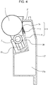
- Fig. 4 is a cross-sectional view of the photosensitive drum cartridge 9.
- the charging roller 2 and cleaning member 6 are disposed in the periphery of the photosensitive drum 1, as described earlier.
- the cleaning member 6 includes a rubber blade 7 and cleaning support member 8.
- a tip portion 7a of the rubber blade 7 is disposed to come into contact with the photosensitive drum 1 in a direction countering the direction of rotation of the photosensitive drum 1. Residual toner removed from the surface of the photosensitive drum 1 by the cleaning member 6 falls into a waste toner chamber 27a.
- a seal sheet 21 that prevents waste toner in the waste toner chamber 27a from leaking comes into contact with the photosensitive drum 1.
- the photosensitive drum 1 is rotationally driven in accordance with image forming operations of the photosensitive drum 1, by transmitting driving force of a main body driving motor (omitted from illustration), that is a drive source, to the drum coupling 16 of the photosensitive drum cartridge 9.
- the charging roller 2 is rotatably attached to the photosensitive drum cartridge 9 via a charge roller bearing 28, pressed toward the photosensitive drum 1 by a pressing member 33 ( Fig. 4 ), and rotates following rotation of the photosensitive drum 1.
- Fig. 5 is a principal section of the developing cartridge 4 (4Y, 4M, 4C, 4K) storing toner in the developing cartridge.
- the developing cartridge 4Y storing yellow-colored toner
- the developing cartridge 4M storing magenta-colored toner
- the developing cartridge 4C storing cyan-colored toner
- the developing cartridge 4K storing black-colored toner
- the developing cartridge 4 has a later-described developing unit 39 including a developing roller 25 and a developing frame 31 (second frame).
- the developing frame 31 rotatably supports the developing roller 25 that comes into contact with the photosensitive drum 1 and rotates in the direction of the arrow C.
- the developing unit 39 further is provided with a toner supplying roller 34 that comes into contact with the developing roller 25 and rotates, and the developing blade 35 that regulates the toner layer on the developing roller 25.
- the developing frame 31 is made up of a developing chamber 31c where the developing roller 25 is disposed, and a toner storage chamber 31a provided below the developing chamber 31c.
- the developing chamber 31c and toner storage chamber 31a are partitioned by a partition 31d.
- An opening 31b is provided in the partition 31d, through which toner passes as it is being conveyed from the toner storage chamber 31a to the developing chamber 31c.
- the developing frame 31 further has a biased member 31e that is biased by the cartridge biasing member 80 provided to the apparatus main body 100A.
- a toner conveyance member 36 that stirs the toner stored in the toner storage chamber 31a, and also conveys toner to the developing chamber 31c via the opening 31b, is provided to the toner storage chamber 31a of the developing frame 31.
- the developing roller 25 and toner supplying roller 34 illustrated in Fig. 5 are rotatably supported by the developing frame 31, by a developing rear bearing 12 and a developing front bearing 13, disposed at respective sides in the axial direction of the developing roller 25, as illustrated in Fig. 6 .
- the developing unit 39 further is provided with a one-end supporting member (first frame member) 38 at one end side in the axial direction of the developing roller 25, and an other-end supporting member 37 at the other end side in the axial direction of the developing roller 25, as illustrated in Fig. 6 .
- the bosses 12a and 13a are cylindrical in shape.
- the developing unit 39 also is provided with a coupling 12b serving as a driving force receiving unit, that receives rotational driving force to rotate the developing roller 25, as illustrated in Figs. 6 and 7 .
- a hole 37d is provided in the other-end supporting member 37 to avoid interference with the coupling 12b, such that the coupling 12b is accommodated within the hole 37d.
- the one-end supporting member 38 and other-end supporting member 37 can pivot with regard to the developing unit 39, on the bosses 13a and 12a pivotably supported by the second rotational center 38a and first rotational center 37a. That is to say, the rotational axis of the one-end supporting member 38 and other-end supporting member 37 as to the developing unit 39 matches a center axis line R of the bosses 13a and 12a. Further, the one-end supporting member 38 and other-end supporting member 37 are each capable of independently moving as to the developing unit 39.
- the developing unit 39 further has a biased member (pressed member) 13b, and a hole (hole portion) 38d is formed in the one-end supporting member 38 so that there is no interference between the biased member 13b and the one-end supporting member 38.
- the biased member 13b is a projection protruding in the direction of the rotational axis (center axis line R) of the second rotational center 38a. Note that the center axis line R is parallel to the rotational axis direction of the developing roller 25 (the longitudinal direction of the developing roller 25).
- the biased member 13b basses through the hole 38d, so as to be capable of coming into contact with a later-described pressing portion 1061.
- Fig. 1 is a diagram illustrating the developing unit 39 mounted to the apparatus main body 100A from the rotational axis direction (center axis line R), with the biased member 13b being disposed on the opposite side of the boss 13a from the biased member 31e.
- a first engaged portion 37b and a first rotation stopper 37c are provided to the other-end supporting member 37.
- the first engaged portion 37b and rotation stopper 37c respectively engage a first engaging portion 98a and a first rotation stopping portion 98b provided to the apparatus main body 100A, after insertion into the apparatus main body 100A.
- the other-end supporting member 37 is positioned in the apparatus main body 100A.
- a second engaged portion 38b and a second rotation stopper 38c are provided to the one-end supporting member 38.
- the second engaged portion 38b and second rotation stopper 38c respectively engage a second engaging portion 99a and a second rotation stopping portion 99b provided to the apparatus main body 100A, after insertion into the apparatus main body 100A.
- the one-end supporting member 38 is positioned in the apparatus main body 100A.
- the bosses 12a and 13a together make up a pivoting center of the developing unit 39.
- the biased member 31e of the developing frame 31 ( Fig. 5 ) is biased in a contact direction A illustrated in Fig. 5 by the biasing member 80, so the developing roller 25 comes into contact with the photosensitive drum 1. That is to say, the developing roller 25 is at a contact position in contact with the photosensitive drum 1.
- the biased member 31e of the developing frame 31 ( Fig. 5 ) is biased in a separating direction B illustrated in Fig.
- the biasing member 80 is movable in the contact direction A and the separating direction B, being driven by a motor (drive source) omitted from illustration, that is provided to the apparatus main body 100A.
- the apparatus main body 100A is provided with mounting opening portions 101 (101a, 101b, 101c, 101d) to which the photosensitive drum cartridges 9 and developing cartridges 4 are mounted, as illustrated in Fig. 8 .
- the photosensitive drum cartridges 9 are mounted/detached to/from the mounting opening portions 101, with the axial direction of the photosensitive drums 1 being the mounting/detaching direction.
- the developing cartridges 4 also are mounted/detached to/from the mounting opening portions 101, with the axial direction of the developing rollers 25 being the mounting/detaching direction. That is to say, the photosensitive drum cartridges 9 and developing cartridges 4 are inserted from the front side toward the rear side.
- this direction F will be referred to as "insertion direction F".
- Upper guide portions 103 (103a, 103b, 103c, 103d) that are first apparatus body guides for the drum cartridges are provided at the upper side of the apparatus main body 100A, as illustrated in Fig. 8 .
- Lower guide portions 102 (102a, 102b, 102c, 102d) that are second apparatus body guides for the drum cartridges are provided at the lower side of the apparatus main body 100A.
- the upper guide portions 103 and lower guide portions 102 are guide shapes each following the insertion direction F of the photosensitive drum cartridges 9.
- Upper guide portions 105 (105a, 105b, 105c, 105d) that are third apparatus body guides for the developing cartridges are provided at the upper side of the apparatus main body 100A.
- Lower guide portions 104 (104a, 104b, 104c, 104d) that are fourth apparatus body guides for the developing cartridges are provided at the lower side of the apparatus main body 100A.
- the upper guide portions 105 and lower guide portions 104 are guide shapes each following the insertion direction F of the developing cartridges 4. Locking Lever 106
- the apparatus main body 100A is provided with locking levers (regulating members) 106 (106a, 106b, 106c, 106d) having the pressing portions 1061 ( Fig. 1 ) coming into contact with the biased members 13b ( Figs. 1 and 6 ) of the developing cartridges 4, as illustrated in Fig. 8 .
- the locking levers 106 (106a, 106b, 106c, 106d) pivot on pivot centers M (Ma, Mb, Mc, Md) as illustrated in Fig. 8 . That is to say, the locking levers 106 are configured so as to be movable in a first direction (P direction) and a second direction (Q direction) that is the opposite direction from the first direction.
- the locking levers 106 thus are capable of moving independently from the cartridge biasing member 80. Accordingly, the locking levers 106 can move when the cartridge biasing member 80 is stationary.
- the locking lever 106 When a user mounts/detaches a photosensitive drum cartridge 9 to/from the apparatus main body 100A, the locking lever 106 is pivoted in the P direction, and when the user mounts/detaches a developing cartridge 4 to/from the apparatus main body 100A, the locking lever 106 is pivoted in the Q direction.
- Insertion (mounting) of a photosensitive drum cartridge 9 and developing cartridge 4 to the apparatus will be described in more detail with reference to Figs. 8 and 9 .
- the locking lever 106 When inserting a developing cartridge 4, the locking lever 106 is moved toward the photosensitive drum cartridge 9 side (in the Q direction in Fig. 8 ), which is a developing cartridge 4 mounting/detaching position (first position) such as illustrated in Fig. 9 .
- This allows mounting/detaching of the developing cartridge 4 to/from the apparatus main body 100A.
- the locking lever 106 is at the developing cartridge mounting/detaching position, the photosensitive drum cartridge 9 cannot be mounted/detached due to interference of the locking lever 106 (mounting/detaching is restricted).
- the developing cartridge mounting/detaching position also is a mounting/detaching restriction position that restricts mounting/detaching of the photosensitive drum cartridge 9.
- the cartridge biasing member 80 is stationary and does not move.
- the photosensitive drum cartridge 9 When inserting a photosensitive drum cartridge 9, the photosensitive drum cartridge 9 is placed on the lower guide portion 102 and upper guide portion 103 at the front side in the mounting direction.
- the locking lever 106 is moved toward the developing cartridge 4 side (in the P direction in Fig. 8 ), which is a drum cartridge mounting/detaching position (second position) such as illustrated in Fig. 1 .
- This allows mounting/detaching of the photosensitive drum cartridge 9 to/from the apparatus main body 100A.
- the locking lever 106 When the locking lever 106 is at the drum cartridge mounting/detaching position, the developing cartridge 4 cannot be mounted/detached due to interference of the locking lever 106 (mounting/detaching is restricted).
- the drum cartridge mounting/detaching position is a mounting/detaching allowing position that allows mounting/detaching of the photosensitive drum cartridge 9.
- the photosensitive drum cartridge 9 is then inserted into the apparatus main body 100A by moving in the insertion direction F following the upper guide portion 103 and lower guide portion 102 for the drum cartridge.
- the developing device has the biased member 13b as illustrated in Fig. 1 , and the locking lever 106 has the pressing portion 1061. Accordingly, moving the locking lever 106 in the P direction when inserting the photosensitive drum cartridge 9 causes the pressing portion 1061 of the locking lever 106 to press the biased member 13b.
- the developing unit 39 in the developing cartridge 4 can be distanced from the photosensitive drum 1, so the photosensitive drum cartridge 9 can be inserted/extracted without damaging the photosensitive drum 1.
- the biased member 13b is being pressed by the pressing portion 1061 of the locking lever 106 and the developing unit 39 is at a position away from the photosensitive drum 1, the developing roller 25 is at a second separated position.
- the second separated position is a position where the developing roller 25 is further away from the photosensitive drum 1 than the first separated position.
- the apparatus main body 100A has a door, omitted from illustration, that opens and closes the mounting opening portion 101.
- the cartridge biasing member 80 always moves in the separating direction B, so the biased member 31e is pressed and moves to the first separated position.
- the user moves the locking lever 106 in the P direction from this state.
- the developing roller 25 further moves from the first separated position to the second separated position.
- the developing cartridge 4 is placed on the upper guide portion 105 and lower guide portion 104 at the front side in the mounting direction.
- the locking lever 106 is moved to the photosensitive drum cartridge 9 side (Q direction).
- the developing cartridge 4 is then inserted into the apparatus main body 100A by moving the developing cartridge 4 in the insertion direction F following the upper guide portion 105 and lower guide portion 104.
- the photosensitive drum cartridge 9 with a second biased member W, corresponding to the biased member 13b of the developing cartridge 4, as illustrated in Fig. 1 , enables the pressing portion 1061 of the locking lever 106 to press the second biased member W by the user moving the locking lever 106 in the Q direction. Accordingly, the photosensitive drum 1 can be distanced from the developing unit 39 of the developing cartridge 4, and the developing cartridge 4 can be inserted/extracted without damaging the photosensitive drum 1.
- the present invention may also be defined by the following statements.
- An image forming apparatus comprising:
Landscapes
- Physics & Mathematics (AREA)
- General Physics & Mathematics (AREA)
- Engineering & Computer Science (AREA)
- Computer Vision & Pattern Recognition (AREA)
- Electrophotography Configuration And Component (AREA)
Applications Claiming Priority (2)
| Application Number | Priority Date | Filing Date | Title |
|---|---|---|---|
| JP2016089066 | 2016-04-27 | ||
| JP2017034505A JP6938166B2 (ja) | 2016-04-27 | 2017-02-27 | 画像形成装置 |
Publications (2)
| Publication Number | Publication Date |
|---|---|
| EP3239782A1 true EP3239782A1 (de) | 2017-11-01 |
| EP3239782B1 EP3239782B1 (de) | 2019-08-21 |
Family
ID=58638687
Family Applications (1)
| Application Number | Title | Priority Date | Filing Date |
|---|---|---|---|
| EP17167509.3A Active EP3239782B1 (de) | 2016-04-27 | 2017-04-21 | Entwicklungsvorrichtung und bilderzeugungseinrichtung |
Country Status (3)
| Country | Link |
|---|---|
| US (1) | US10139774B2 (de) |
| EP (1) | EP3239782B1 (de) |
| CN (1) | CN107315334B (de) |
Cited By (1)
| Publication number | Priority date | Publication date | Assignee | Title |
|---|---|---|---|---|
| EP3584639A1 (de) * | 2016-11-01 | 2019-12-25 | Canon Kabushiki Kaisha | Bilderzeugungsvorrichtung |
Families Citing this family (6)
| Publication number | Priority date | Publication date | Assignee | Title |
|---|---|---|---|---|
| JP6746330B2 (ja) * | 2016-03-11 | 2020-08-26 | キヤノン株式会社 | 現像カートリッジおよび画像形成装置 |
| JP7006557B2 (ja) | 2018-09-28 | 2022-01-24 | ブラザー工業株式会社 | 画像形成装置 |
| JP7255378B2 (ja) * | 2019-06-13 | 2023-04-11 | 京セラドキュメントソリューションズ株式会社 | 画像形成装置 |
| JP7483541B2 (ja) * | 2019-09-17 | 2024-05-15 | キヤノン株式会社 | カートリッジ及び画像形成装置 |
| JP7562379B2 (ja) * | 2020-11-10 | 2024-10-07 | キヤノン株式会社 | 画像形成装置及び画像形成システム |
| JP7608220B2 (ja) * | 2021-03-10 | 2025-01-06 | キヤノン株式会社 | 画像形成装置 |
Citations (6)
| Publication number | Priority date | Publication date | Assignee | Title |
|---|---|---|---|---|
| JPH0567913B2 (de) | 1986-04-16 | 1993-09-27 | Sundstrand Corp | |
| JPH06348123A (ja) | 1993-06-09 | 1994-12-22 | Ricoh Co Ltd | 画像形成装置 |
| US20090317133A1 (en) * | 2008-06-24 | 2009-12-24 | Brother Kogyo Kabushiki Kaisha | Image Forming Device Having Detachable Developing Device Unit |
| EP2333615A1 (de) * | 2008-09-29 | 2011-06-15 | Canon Kabushiki Kaisha | Elektrofotografische bildgebungsvorrichtung |
| US20120321342A1 (en) * | 2011-06-17 | 2012-12-20 | Canon Kabushiki Kaisha | Process cartridge, electrophotographic image forming apparatus, and assembly method of process cartridge |
| US20150227110A1 (en) * | 2012-09-07 | 2015-08-13 | Canon Kabushiki Kaisha | Image forming apparatus, and process cartridge |
Family Cites Families (15)
| Publication number | Priority date | Publication date | Assignee | Title |
|---|---|---|---|---|
| EP1637933B1 (de) * | 2004-08-06 | 2010-07-28 | Brother Kogyo Kabushiki Kaisha | Elektrische und mechanische Verbindungen an Behälter für ein lichtempfindliches Element, Entwicklungseinheit und Arbeitseinheit |
| JP4040636B2 (ja) | 2005-03-24 | 2008-01-30 | キヤノン株式会社 | プロセスカートリッジ及び電子写真画像形成装置 |
| JP4241865B2 (ja) * | 2006-12-08 | 2009-03-18 | キヤノン株式会社 | プロセスカートリッジ及び電子写真画像形成装置 |
| JP4841000B2 (ja) * | 2006-12-11 | 2011-12-21 | キヤノン株式会社 | 現像剤容器、現像装置、及びプロセスカートリッジ |
| JP2009139518A (ja) | 2007-12-05 | 2009-06-25 | Sharp Corp | 画像形成装置 |
| JP4793430B2 (ja) * | 2008-12-05 | 2011-10-12 | コニカミノルタビジネステクノロジーズ株式会社 | 画像形成装置 |
| JP4968301B2 (ja) * | 2009-09-11 | 2012-07-04 | ブラザー工業株式会社 | 画像形成装置およびタンデム型感光体ユニット |
| JP5761948B2 (ja) | 2010-09-14 | 2015-08-12 | キヤノン株式会社 | 電子写真画像形成装置 |
| JP2012073288A (ja) * | 2010-09-27 | 2012-04-12 | Fuji Xerox Co Ltd | 画像形成装置 |
| JP5935391B2 (ja) | 2012-02-29 | 2016-06-15 | ブラザー工業株式会社 | 画像形成装置 |
| JP5067913B2 (ja) | 2012-05-16 | 2012-11-07 | キヤノン株式会社 | プロセスカートリッジ、及び電子写真画像形成装置 |
| JP5523503B2 (ja) * | 2012-05-24 | 2014-06-18 | キヤノン株式会社 | プロセスカートリッジ及び画像形成装置 |
| JP6007596B2 (ja) * | 2012-05-31 | 2016-10-12 | ブラザー工業株式会社 | 画像形成装置 |
| JP6184311B2 (ja) * | 2012-12-14 | 2017-08-23 | キヤノン株式会社 | プロセスカートリッジ及び画像形成装置 |
| JP5716083B2 (ja) | 2013-12-27 | 2015-05-13 | 京セラドキュメントソリューションズ株式会社 | 画像形成装置 |
-
2017
- 2017-04-21 EP EP17167509.3A patent/EP3239782B1/de active Active
- 2017-04-21 US US15/494,376 patent/US10139774B2/en active Active
- 2017-04-27 CN CN201710284782.XA patent/CN107315334B/zh active Active
Patent Citations (6)
| Publication number | Priority date | Publication date | Assignee | Title |
|---|---|---|---|---|
| JPH0567913B2 (de) | 1986-04-16 | 1993-09-27 | Sundstrand Corp | |
| JPH06348123A (ja) | 1993-06-09 | 1994-12-22 | Ricoh Co Ltd | 画像形成装置 |
| US20090317133A1 (en) * | 2008-06-24 | 2009-12-24 | Brother Kogyo Kabushiki Kaisha | Image Forming Device Having Detachable Developing Device Unit |
| EP2333615A1 (de) * | 2008-09-29 | 2011-06-15 | Canon Kabushiki Kaisha | Elektrofotografische bildgebungsvorrichtung |
| US20120321342A1 (en) * | 2011-06-17 | 2012-12-20 | Canon Kabushiki Kaisha | Process cartridge, electrophotographic image forming apparatus, and assembly method of process cartridge |
| US20150227110A1 (en) * | 2012-09-07 | 2015-08-13 | Canon Kabushiki Kaisha | Image forming apparatus, and process cartridge |
Cited By (2)
| Publication number | Priority date | Publication date | Assignee | Title |
|---|---|---|---|---|
| EP3584639A1 (de) * | 2016-11-01 | 2019-12-25 | Canon Kabushiki Kaisha | Bilderzeugungsvorrichtung |
| US10852687B2 (en) | 2016-11-01 | 2020-12-01 | Canon Kabushiki Kaisha | Image forming apparatus |
Also Published As
| Publication number | Publication date |
|---|---|
| CN107315334A (zh) | 2017-11-03 |
| CN107315334B (zh) | 2021-04-13 |
| EP3239782B1 (de) | 2019-08-21 |
| US10139774B2 (en) | 2018-11-27 |
| US20170315498A1 (en) | 2017-11-02 |
Similar Documents
| Publication | Publication Date | Title |
|---|---|---|
| EP3239782B1 (de) | Entwicklungsvorrichtung und bilderzeugungseinrichtung | |
| JP6990822B2 (ja) | 現像装置、プロセスカートリッジおよび画像形成装置 | |
| KR102333305B1 (ko) | 화상형성장치의 본체에 장착가능한 현상 카트리지 | |
| JP4684732B2 (ja) | 電子写真画像形成装置およびプロセスカートリッジ | |
| EP3211482A1 (de) | Entwicklungskartusche und bilderzeugungsvorrichtung | |
| EP3211483B1 (de) | Entwicklungskartusche und bilderzeugungsvorrichtung | |
| JP7192063B2 (ja) | 現像カートリッジおよび画像形成装置 | |
| US10663914B2 (en) | Image forming apparatus having releasable drum unit | |
| US9857761B2 (en) | Image forming apparatus having a supporting member for dismountably supporting one or more cartridges | |
| JP6938166B2 (ja) | 画像形成装置 | |
| JP2017156474A (ja) | 現像カートリッジ | |
| EP3462243B1 (de) | Entwicklungsvorrichtung und bilderzeugungsvorrichtung | |
| JP7214419B2 (ja) | 画像形成装置、現像カートリッジ | |
| JP2011022618A (ja) | 電子写真画像形成装置およびプロセスカートリッジ | |
| JP2017156744A (ja) | 現像カートリッジ、画像形成装置 | |
| CN110941167B (zh) | 成像设备和显影盒 | |
| JP2017173421A (ja) | 画像形成装置 | |
| KR20170101806A (ko) | 현상장치, 프로세스 카트리지 및 화상형성장치 |
Legal Events
| Date | Code | Title | Description |
|---|---|---|---|
| PUAI | Public reference made under article 153(3) epc to a published international application that has entered the european phase |
Free format text: ORIGINAL CODE: 0009012 |
|
| STAA | Information on the status of an ep patent application or granted ep patent |
Free format text: STATUS: THE APPLICATION HAS BEEN PUBLISHED |
|
| AK | Designated contracting states |
Kind code of ref document: A1 Designated state(s): AL AT BE BG CH CY CZ DE DK EE ES FI FR GB GR HR HU IE IS IT LI LT LU LV MC MK MT NL NO PL PT RO RS SE SI SK SM TR |
|
| AX | Request for extension of the european patent |
Extension state: BA ME |
|
| STAA | Information on the status of an ep patent application or granted ep patent |
Free format text: STATUS: REQUEST FOR EXAMINATION WAS MADE |
|
| 17P | Request for examination filed |
Effective date: 20180502 |
|
| RBV | Designated contracting states (corrected) |
Designated state(s): AL AT BE BG CH CY CZ DE DK EE ES FI FR GB GR HR HU IE IS IT LI LT LU LV MC MK MT NL NO PL PT RO RS SE SI SK SM TR |
|
| STAA | Information on the status of an ep patent application or granted ep patent |
Free format text: STATUS: EXAMINATION IS IN PROGRESS |
|
| 17Q | First examination report despatched |
Effective date: 20180814 |
|
| GRAP | Despatch of communication of intention to grant a patent |
Free format text: ORIGINAL CODE: EPIDOSNIGR1 |
|
| STAA | Information on the status of an ep patent application or granted ep patent |
Free format text: STATUS: GRANT OF PATENT IS INTENDED |
|
| INTG | Intention to grant announced |
Effective date: 20190326 |
|
| GRAS | Grant fee paid |
Free format text: ORIGINAL CODE: EPIDOSNIGR3 |
|
| GRAA | (expected) grant |
Free format text: ORIGINAL CODE: 0009210 |
|
| STAA | Information on the status of an ep patent application or granted ep patent |
Free format text: STATUS: THE PATENT HAS BEEN GRANTED |
|
| AK | Designated contracting states |
Kind code of ref document: B1 Designated state(s): AL AT BE BG CH CY CZ DE DK EE ES FI FR GB GR HR HU IE IS IT LI LT LU LV MC MK MT NL NO PL PT RO RS SE SI SK SM TR |
|
| REG | Reference to a national code |
Ref country code: GB Ref legal event code: FG4D |
|
| REG | Reference to a national code |
Ref country code: CH Ref legal event code: EP |
|
| REG | Reference to a national code |
Ref country code: DE Ref legal event code: R096 Ref document number: 602017006249 Country of ref document: DE |
|
| REG | Reference to a national code |
Ref country code: AT Ref legal event code: REF Ref document number: 1170434 Country of ref document: AT Kind code of ref document: T Effective date: 20190915 |
|
| REG | Reference to a national code |
Ref country code: IE Ref legal event code: FG4D |
|
| REG | Reference to a national code |
Ref country code: LT Ref legal event code: MG4D |
|
| REG | Reference to a national code |
Ref country code: NL Ref legal event code: MP Effective date: 20190821 |
|
| PG25 | Lapsed in a contracting state [announced via postgrant information from national office to epo] |
Ref country code: NL Free format text: LAPSE BECAUSE OF FAILURE TO SUBMIT A TRANSLATION OF THE DESCRIPTION OR TO PAY THE FEE WITHIN THE PRESCRIBED TIME-LIMIT Effective date: 20190821 Ref country code: SE Free format text: LAPSE BECAUSE OF FAILURE TO SUBMIT A TRANSLATION OF THE DESCRIPTION OR TO PAY THE FEE WITHIN THE PRESCRIBED TIME-LIMIT Effective date: 20190821 Ref country code: BG Free format text: LAPSE BECAUSE OF FAILURE TO SUBMIT A TRANSLATION OF THE DESCRIPTION OR TO PAY THE FEE WITHIN THE PRESCRIBED TIME-LIMIT Effective date: 20191121 Ref country code: HR Free format text: LAPSE BECAUSE OF FAILURE TO SUBMIT A TRANSLATION OF THE DESCRIPTION OR TO PAY THE FEE WITHIN THE PRESCRIBED TIME-LIMIT Effective date: 20190821 Ref country code: LT Free format text: LAPSE BECAUSE OF FAILURE TO SUBMIT A TRANSLATION OF THE DESCRIPTION OR TO PAY THE FEE WITHIN THE PRESCRIBED TIME-LIMIT Effective date: 20190821 Ref country code: NO Free format text: LAPSE BECAUSE OF FAILURE TO SUBMIT A TRANSLATION OF THE DESCRIPTION OR TO PAY THE FEE WITHIN THE PRESCRIBED TIME-LIMIT Effective date: 20191121 Ref country code: PT Free format text: LAPSE BECAUSE OF FAILURE TO SUBMIT A TRANSLATION OF THE DESCRIPTION OR TO PAY THE FEE WITHIN THE PRESCRIBED TIME-LIMIT Effective date: 20191223 Ref country code: FI Free format text: LAPSE BECAUSE OF FAILURE TO SUBMIT A TRANSLATION OF THE DESCRIPTION OR TO PAY THE FEE WITHIN THE PRESCRIBED TIME-LIMIT Effective date: 20190821 |
|
| PG25 | Lapsed in a contracting state [announced via postgrant information from national office to epo] |
Ref country code: LV Free format text: LAPSE BECAUSE OF FAILURE TO SUBMIT A TRANSLATION OF THE DESCRIPTION OR TO PAY THE FEE WITHIN THE PRESCRIBED TIME-LIMIT Effective date: 20190821 Ref country code: AL Free format text: LAPSE BECAUSE OF FAILURE TO SUBMIT A TRANSLATION OF THE DESCRIPTION OR TO PAY THE FEE WITHIN THE PRESCRIBED TIME-LIMIT Effective date: 20190821 Ref country code: GR Free format text: LAPSE BECAUSE OF FAILURE TO SUBMIT A TRANSLATION OF THE DESCRIPTION OR TO PAY THE FEE WITHIN THE PRESCRIBED TIME-LIMIT Effective date: 20191122 Ref country code: IS Free format text: LAPSE BECAUSE OF FAILURE TO SUBMIT A TRANSLATION OF THE DESCRIPTION OR TO PAY THE FEE WITHIN THE PRESCRIBED TIME-LIMIT Effective date: 20191221 Ref country code: RS Free format text: LAPSE BECAUSE OF FAILURE TO SUBMIT A TRANSLATION OF THE DESCRIPTION OR TO PAY THE FEE WITHIN THE PRESCRIBED TIME-LIMIT Effective date: 20190821 |
|
| REG | Reference to a national code |
Ref country code: AT Ref legal event code: MK05 Ref document number: 1170434 Country of ref document: AT Kind code of ref document: T Effective date: 20190821 |
|
| PG25 | Lapsed in a contracting state [announced via postgrant information from national office to epo] |
Ref country code: TR Free format text: LAPSE BECAUSE OF FAILURE TO SUBMIT A TRANSLATION OF THE DESCRIPTION OR TO PAY THE FEE WITHIN THE PRESCRIBED TIME-LIMIT Effective date: 20190821 |
|
| PG25 | Lapsed in a contracting state [announced via postgrant information from national office to epo] |
Ref country code: AT Free format text: LAPSE BECAUSE OF FAILURE TO SUBMIT A TRANSLATION OF THE DESCRIPTION OR TO PAY THE FEE WITHIN THE PRESCRIBED TIME-LIMIT Effective date: 20190821 Ref country code: PL Free format text: LAPSE BECAUSE OF FAILURE TO SUBMIT A TRANSLATION OF THE DESCRIPTION OR TO PAY THE FEE WITHIN THE PRESCRIBED TIME-LIMIT Effective date: 20190821 Ref country code: RO Free format text: LAPSE BECAUSE OF FAILURE TO SUBMIT A TRANSLATION OF THE DESCRIPTION OR TO PAY THE FEE WITHIN THE PRESCRIBED TIME-LIMIT Effective date: 20190821 Ref country code: IT Free format text: LAPSE BECAUSE OF FAILURE TO SUBMIT A TRANSLATION OF THE DESCRIPTION OR TO PAY THE FEE WITHIN THE PRESCRIBED TIME-LIMIT Effective date: 20190821 Ref country code: EE Free format text: LAPSE BECAUSE OF FAILURE TO SUBMIT A TRANSLATION OF THE DESCRIPTION OR TO PAY THE FEE WITHIN THE PRESCRIBED TIME-LIMIT Effective date: 20190821 Ref country code: DK Free format text: LAPSE BECAUSE OF FAILURE TO SUBMIT A TRANSLATION OF THE DESCRIPTION OR TO PAY THE FEE WITHIN THE PRESCRIBED TIME-LIMIT Effective date: 20190821 |
|
| PG25 | Lapsed in a contracting state [announced via postgrant information from national office to epo] |
Ref country code: SM Free format text: LAPSE BECAUSE OF FAILURE TO SUBMIT A TRANSLATION OF THE DESCRIPTION OR TO PAY THE FEE WITHIN THE PRESCRIBED TIME-LIMIT Effective date: 20190821 Ref country code: CZ Free format text: LAPSE BECAUSE OF FAILURE TO SUBMIT A TRANSLATION OF THE DESCRIPTION OR TO PAY THE FEE WITHIN THE PRESCRIBED TIME-LIMIT Effective date: 20190821 Ref country code: SK Free format text: LAPSE BECAUSE OF FAILURE TO SUBMIT A TRANSLATION OF THE DESCRIPTION OR TO PAY THE FEE WITHIN THE PRESCRIBED TIME-LIMIT Effective date: 20190821 Ref country code: IS Free format text: LAPSE BECAUSE OF FAILURE TO SUBMIT A TRANSLATION OF THE DESCRIPTION OR TO PAY THE FEE WITHIN THE PRESCRIBED TIME-LIMIT Effective date: 20200224 |
|
| REG | Reference to a national code |
Ref country code: DE Ref legal event code: R097 Ref document number: 602017006249 Country of ref document: DE |
|
| PLBE | No opposition filed within time limit |
Free format text: ORIGINAL CODE: 0009261 |
|
| STAA | Information on the status of an ep patent application or granted ep patent |
Free format text: STATUS: NO OPPOSITION FILED WITHIN TIME LIMIT |
|
| PG2D | Information on lapse in contracting state deleted |
Ref country code: IS |
|
| 26N | No opposition filed |
Effective date: 20200603 |
|
| PG25 | Lapsed in a contracting state [announced via postgrant information from national office to epo] |
Ref country code: SI Free format text: LAPSE BECAUSE OF FAILURE TO SUBMIT A TRANSLATION OF THE DESCRIPTION OR TO PAY THE FEE WITHIN THE PRESCRIBED TIME-LIMIT Effective date: 20190821 |
|
| PG25 | Lapsed in a contracting state [announced via postgrant information from national office to epo] |
Ref country code: ES Free format text: LAPSE BECAUSE OF FAILURE TO SUBMIT A TRANSLATION OF THE DESCRIPTION OR TO PAY THE FEE WITHIN THE PRESCRIBED TIME-LIMIT Effective date: 20190821 |
|
| PG25 | Lapsed in a contracting state [announced via postgrant information from national office to epo] |
Ref country code: MC Free format text: LAPSE BECAUSE OF FAILURE TO SUBMIT A TRANSLATION OF THE DESCRIPTION OR TO PAY THE FEE WITHIN THE PRESCRIBED TIME-LIMIT Effective date: 20190821 |
|
| REG | Reference to a national code |
Ref country code: CH Ref legal event code: PL |
|
| PG25 | Lapsed in a contracting state [announced via postgrant information from national office to epo] |
Ref country code: CH Free format text: LAPSE BECAUSE OF NON-PAYMENT OF DUE FEES Effective date: 20200430 Ref country code: LU Free format text: LAPSE BECAUSE OF NON-PAYMENT OF DUE FEES Effective date: 20200421 Ref country code: LI Free format text: LAPSE BECAUSE OF NON-PAYMENT OF DUE FEES Effective date: 20200430 |
|
| REG | Reference to a national code |
Ref country code: BE Ref legal event code: MM Effective date: 20200430 |
|
| PG25 | Lapsed in a contracting state [announced via postgrant information from national office to epo] |
Ref country code: BE Free format text: LAPSE BECAUSE OF NON-PAYMENT OF DUE FEES Effective date: 20200430 |
|
| PG25 | Lapsed in a contracting state [announced via postgrant information from national office to epo] |
Ref country code: IE Free format text: LAPSE BECAUSE OF NON-PAYMENT OF DUE FEES Effective date: 20200421 |
|
| PG25 | Lapsed in a contracting state [announced via postgrant information from national office to epo] |
Ref country code: MT Free format text: LAPSE BECAUSE OF FAILURE TO SUBMIT A TRANSLATION OF THE DESCRIPTION OR TO PAY THE FEE WITHIN THE PRESCRIBED TIME-LIMIT Effective date: 20190821 Ref country code: CY Free format text: LAPSE BECAUSE OF FAILURE TO SUBMIT A TRANSLATION OF THE DESCRIPTION OR TO PAY THE FEE WITHIN THE PRESCRIBED TIME-LIMIT Effective date: 20190821 |
|
| PG25 | Lapsed in a contracting state [announced via postgrant information from national office to epo] |
Ref country code: MK Free format text: LAPSE BECAUSE OF FAILURE TO SUBMIT A TRANSLATION OF THE DESCRIPTION OR TO PAY THE FEE WITHIN THE PRESCRIBED TIME-LIMIT Effective date: 20190821 |
|
| PGFP | Annual fee paid to national office [announced via postgrant information from national office to epo] |
Ref country code: DE Payment date: 20250319 Year of fee payment: 9 |
|
| PGFP | Annual fee paid to national office [announced via postgrant information from national office to epo] |
Ref country code: GB Payment date: 20260319 Year of fee payment: 10 |
|
| PGFP | Annual fee paid to national office [announced via postgrant information from national office to epo] |
Ref country code: FR Payment date: 20260319 Year of fee payment: 10 |