EP3243015B1 - Système et procédé de mesure permettant de détecter des grandeurs sur les porte-satellites d'un train planétaire - Google Patents
Système et procédé de mesure permettant de détecter des grandeurs sur les porte-satellites d'un train planétaire Download PDFInfo
- Publication number
- EP3243015B1 EP3243015B1 EP16709733.6A EP16709733A EP3243015B1 EP 3243015 B1 EP3243015 B1 EP 3243015B1 EP 16709733 A EP16709733 A EP 16709733A EP 3243015 B1 EP3243015 B1 EP 3243015B1
- Authority
- EP
- European Patent Office
- Prior art keywords
- planetary gear
- sensor
- planet
- measuring system
- electronics
- Prior art date
- Legal status (The legal status is an assumption and is not a legal conclusion. Google has not performed a legal analysis and makes no representation as to the accuracy of the status listed.)
- Active
Links
Images


Classifications
-
- F—MECHANICAL ENGINEERING; LIGHTING; HEATING; WEAPONS; BLASTING
- F16—ENGINEERING ELEMENTS AND UNITS; GENERAL MEASURES FOR PRODUCING AND MAINTAINING EFFECTIVE FUNCTIONING OF MACHINES OR INSTALLATIONS; THERMAL INSULATION IN GENERAL
- F16H—GEARING
- F16H57/00—General details of gearing
- F16H57/01—Monitoring wear or stress of gearing elements, e.g. for triggering maintenance
-
- G—PHYSICS
- G01—MEASURING; TESTING
- G01M—TESTING STATIC OR DYNAMIC BALANCE OF MACHINES OR STRUCTURES; TESTING OF STRUCTURES OR APPARATUS, NOT OTHERWISE PROVIDED FOR
- G01M13/00—Testing of machine parts
- G01M13/02—Gearings; Transmission mechanisms
- G01M13/021—Gearings
-
- H—ELECTRICITY
- H04—ELECTRIC COMMUNICATION TECHNIQUE
- H04Q—SELECTING
- H04Q9/00—Arrangements in telecontrol or telemetry systems for selectively calling a substation from a main station, in which substation desired apparatus is selected for applying a control signal thereto or for obtaining measured values therefrom
-
- F—MECHANICAL ENGINEERING; LIGHTING; HEATING; WEAPONS; BLASTING
- F03—MACHINES OR ENGINES FOR LIQUIDS; WIND, SPRING, OR WEIGHT MOTORS; PRODUCING MECHANICAL POWER OR A REACTIVE PROPULSIVE THRUST, NOT OTHERWISE PROVIDED FOR
- F03D—WIND MOTORS
- F03D15/00—Transmission of mechanical power
-
- F—MECHANICAL ENGINEERING; LIGHTING; HEATING; WEAPONS; BLASTING
- F03—MACHINES OR ENGINES FOR LIQUIDS; WIND, SPRING, OR WEIGHT MOTORS; PRODUCING MECHANICAL POWER OR A REACTIVE PROPULSIVE THRUST, NOT OTHERWISE PROVIDED FOR
- F03D—WIND MOTORS
- F03D17/00—Monitoring or testing of wind motors, e.g. diagnostics
-
- F—MECHANICAL ENGINEERING; LIGHTING; HEATING; WEAPONS; BLASTING
- F05—INDEXING SCHEMES RELATING TO ENGINES OR PUMPS IN VARIOUS SUBCLASSES OF CLASSES F01-F04
- F05B—INDEXING SCHEME RELATING TO WIND, SPRING, WEIGHT, INERTIA OR LIKE MOTORS, TO MACHINES OR ENGINES FOR LIQUIDS COVERED BY SUBCLASSES F03B, F03D AND F03G
- F05B2260/00—Function
- F05B2260/40—Transmission of power
- F05B2260/403—Transmission of power through the shape of the drive components
- F05B2260/4031—Transmission of power through the shape of the drive components as in toothed gearing
- F05B2260/40311—Transmission of power through the shape of the drive components as in toothed gearing of the epicyclic, planetary or differential type
-
- F—MECHANICAL ENGINEERING; LIGHTING; HEATING; WEAPONS; BLASTING
- F16—ENGINEERING ELEMENTS AND UNITS; GENERAL MEASURES FOR PRODUCING AND MAINTAINING EFFECTIVE FUNCTIONING OF MACHINES OR INSTALLATIONS; THERMAL INSULATION IN GENERAL
- F16H—GEARING
- F16H1/00—Toothed gearings for conveying rotary motion
- F16H1/28—Toothed gearings for conveying rotary motion with gears having orbital motion
- F16H1/46—Systems consisting of a plurality of gear trains each with orbital gears, i.e. systems having three or more central gears
-
- F—MECHANICAL ENGINEERING; LIGHTING; HEATING; WEAPONS; BLASTING
- F16—ENGINEERING ELEMENTS AND UNITS; GENERAL MEASURES FOR PRODUCING AND MAINTAINING EFFECTIVE FUNCTIONING OF MACHINES OR INSTALLATIONS; THERMAL INSULATION IN GENERAL
- F16H—GEARING
- F16H57/00—General details of gearing
- F16H57/01—Monitoring wear or stress of gearing elements, e.g. for triggering maintenance
- F16H2057/012—Monitoring wear or stress of gearing elements, e.g. for triggering maintenance of gearings
-
- F—MECHANICAL ENGINEERING; LIGHTING; HEATING; WEAPONS; BLASTING
- F16—ENGINEERING ELEMENTS AND UNITS; GENERAL MEASURES FOR PRODUCING AND MAINTAINING EFFECTIVE FUNCTIONING OF MACHINES OR INSTALLATIONS; THERMAL INSULATION IN GENERAL
- F16H—GEARING
- F16H57/00—General details of gearing
- F16H57/08—General details of gearing of gearings with members having orbital motion
- F16H57/082—Planet carriers
-
- H—ELECTRICITY
- H04—ELECTRIC COMMUNICATION TECHNIQUE
- H04Q—SELECTING
- H04Q2209/00—Arrangements in telecontrol or telemetry systems
- H04Q2209/30—Arrangements in telecontrol or telemetry systems using a wired architecture
-
- H—ELECTRICITY
- H04—ELECTRIC COMMUNICATION TECHNIQUE
- H04Q—SELECTING
- H04Q2209/00—Arrangements in telecontrol or telemetry systems
- H04Q2209/40—Arrangements in telecontrol or telemetry systems using a wireless architecture
-
- H—ELECTRICITY
- H04—ELECTRIC COMMUNICATION TECHNIQUE
- H04Q—SELECTING
- H04Q2209/00—Arrangements in telecontrol or telemetry systems
- H04Q2209/80—Arrangements in the sub-station, i.e. sensing device
- H04Q2209/88—Providing power supply at the sub-station
-
- H—ELECTRICITY
- H04—ELECTRIC COMMUNICATION TECHNIQUE
- H04Q—SELECTING
- H04Q2209/00—Arrangements in telecontrol or telemetry systems
- H04Q2209/80—Arrangements in the sub-station, i.e. sensing device
- H04Q2209/88—Providing power supply at the sub-station
- H04Q2209/886—Providing power supply at the sub-station using energy harvesting, e.g. solar, wind or mechanical
-
- Y—GENERAL TAGGING OF NEW TECHNOLOGICAL DEVELOPMENTS; GENERAL TAGGING OF CROSS-SECTIONAL TECHNOLOGIES SPANNING OVER SEVERAL SECTIONS OF THE IPC; TECHNICAL SUBJECTS COVERED BY FORMER USPC CROSS-REFERENCE ART COLLECTIONS [XRACs] AND DIGESTS
- Y02—TECHNOLOGIES OR APPLICATIONS FOR MITIGATION OR ADAPTATION AGAINST CLIMATE CHANGE
- Y02E—REDUCTION OF GREENHOUSE GAS [GHG] EMISSIONS, RELATED TO ENERGY GENERATION, TRANSMISSION OR DISTRIBUTION
- Y02E10/00—Energy generation through renewable energy sources
- Y02E10/70—Wind energy
- Y02E10/72—Wind turbines with rotation axis in wind direction
Definitions
- the invention relates to a measuring system for detecting quantities on planet carriers of a planetary gear comprising at least several planetary gear stages, wherein each planetary gear stage has at least one sun shaft, at least one ring gear and at least one planet gear that is connected to the respective sun shaft and the respective ring gear by a tooth engagement and each include a planet carrier associated with the at least one planet gear, which is rotationally connected to the at least one planet gear.
- Planetary gear units offer significant advantages over conventional helical and bevel-helical gear units in terms of power density and specific torque and include a sun shaft, a planet carrier with planet gears and an internally toothed ring gear. Due to the cylindrical basic shape of the ring gears, planetary gear units for industrial applications often have a cylindrical design. Planetary gearboxes can be mounted as slip-on gearboxes with a torque arm, as screw-on or flange-mounted gearboxes or in a foot-standing position with an additional frame.
- Bearings are one of the most common causes of failure in gearboxes, especially wind power gearboxes.
- Various sensors and measuring systems are used to monitor and assess these bearings.
- the transmission path from the signal source to the sensor is of crucial importance.
- pressure, temperature and vibration / acceleration measuring sensors are usually attached as "fixed" sensors in the stationary coordinate system.
- rotatingly monitoring the rotating planet wheels of the various stages of a planetary gear there is no associated possibility of rotatingly monitoring the rotating planet wheels of the various stages of a planetary gear.
- rotating monitoring of the second or third or subsequent stages of a planetary gear has not previously been possible.
- so-called “telemetry” sensors are generally installed in the rotating coordinate system.
- these systems require energy.
- the energy supply is either designed using slip rings or e.g. via a battery. However, this is not designed for life.
- a monitoring system for a planetary gear which comprises a base station which is connected to an antenna.
- the antenna interacts wirelessly with sensors that are designed to detect a temperature or vibrations. There is a wireless transmission of data and energy between the antenna and the sensors.
- the sensors can also be attached to a planet carrier, to a bearing or to a planet gear axle.
- the publication US 2008/0279686 A1 discloses a transmission of a wind turbine, which is equipped with a sensor.
- the sensor is designed to detect vibrations and is connected to a data processing unit via a data transmission device.
- the data exchange and the energy transfer take place wirelessly between the sensor and the data processing device.
- the sensor is attached to the planet carrier.
- the first and second object of the invention is therefore to provide a measuring system for planetary gear bearing monitoring and a measuring method which is particularly suitable for detecting the sizes of the second and subsequent stages of a multi-stage planetary gear.
- the first object is achieved by specifying a measuring system for recording quantities on planet carriers of a planetary gear, comprising at least several planetary gear stages, at least each planetary gear stage each having a sun shaft, at least one ring gear in each case and at least one planet gear each having the respective sun shaft and the respective one Ring gear is connected by a tooth engagement and each comprises a planet carrier associated with the at least one planet gear, which is rotationally connected to the at least one planet gear, at least one first sensor having at least one connection for supplying the first sensor with electrical energy on at least one of the Planet carrier is arranged on at least one of the planetary gear stages for detecting the sizes of the associated planetary gear, and wherein the planetary gear has electronics by means of which the at least one first sensor can be supplied with electrical energy is and at least a planetary gear stage can be selected from each of the existing planetary gear stages.
- the second object is achieved by specifying a measuring method for detecting quantities on planet carriers of a planetary gear, comprising at least several planetary gear stages, at least each planetary gear stage each having a sun shaft, at least one ring gear and at least one planet gear each, which is associated with the respective sun shaft and the respective one Ring gear is connected by a tooth engagement and each comprises a planet carrier associated with the at least one planet gear, which is rotationally connected to the at least one planet gear, with at least one first sensor attached to at least one of the planet carriers on at least one of the planet gear stages and having at least one connection for Supply of the at least one first sensor with electrical energy, a detection of the sizes of the associated planetary gear is made possible and wherein the electronics of the planetary gear with the at least one first sensor electrical energy is supplied and the at least one planetary gear stage can be selected from each of the available planetary gear stages.
- each individual bearing of a planetary gear can be measured.
- All planetary gear stages can thus be recorded and monitored.
- the physical quantities measurable under difficult environmental conditions e.g. oil, temperature, rotary movement etc.
- vibration, acceleration, temperature, oil pressure, etc. can also be recorded here.
- an energy supply of the sensor system is on the rotating one Waves possible. Data communication to the sensors is also possible thanks to the energy supply.
- the proposed arrangement of the sensor (s), if present, enables each individual planet gear to be continuously monitored during operation. Signs of wear can be caused by the possibility of detecting the oil pressure and the vibrations of the planet gears rotating around the sun shaft at the point of wear in the bearing.
- the electronics comprise first and second electronics.
- the second electronics are arranged on the front (front) of the first sun shaft of the first planetary gear stage.
- the accessibility of the sun shaft via the rotor hub can be given. It is therefore possible to reach the electronics (customer interface) at this location.
- This location is very easy to reach, for example, by disassembling a pitch tube cover that is usually present in the planet carrier. This makes it easy to replace the electronics when servicing and during the life of the system.
- the electronics supply the at least one first sensor with energy in a contactless or wireless manner.
- the wireless energy supply can be an inductive coupling, resonant inductive coupling or a capacitive coupling with a coupling factor.
- At least one planetary gear stage preferably comprises a plurality of planetary gears, with the at least one first sensor being able to monitor all planetary gears.
- the electronics are preferably arranged on the first planet carrier, the sun shaft being at least partially designed as a hollow shaft and the electronics having a first electrical connecting line guided through this hollow shaft.
- the electronics can be a 25 kHz transformer; the secondary coil can be designed as a flexible printed circuit board. This arrangement enables the electronics to be supplied in a particularly simple manner without any effort or conversion of the transmission.
- the sensors arranged on other planet carriers are then supplied with energy by these electronics in a contactless or wireless manner. Due to the cable connection of the electronics, there is sufficient energy available for such a transmission or this can be supplied with sufficient energy.
- the first planetary gear stage can also have at least one second sensor.
- a second electrical connection line from the electronics to the second sensor of the first planetary gear stage is provided for supplying the second sensor of the first planetary gear stage with energy.
- this second sensor can alternatively be supplied wirelessly with energy by the electronics.
- a digital interface for transmitting the data to a data processing system is preferably provided.
- the digital interface is arranged on the end (front) of the at least one planet carrier of the first planetary gear stage.
- Access to the second planetary gear stage is wireless or radio, both for the energy and the data. As already described above, this location can be easily reached by disassembling the pitch tube cover in the planet carrier. This makes it easy to replace the digital interface when servicing and during the lifetime of the system.
- the sensors can be configured with antennas for the transmission of the data.
- the sun shaft is preferably at least partially designed as a hollow shaft, and a data transmission cable can be guided through this hollow shaft to the digital interface. This ensures a secure and fast data connection without changing or adapting the structure of the gear unit to an external evaluation station.
- the data transmission preferably takes place contactlessly or wirelessly from the at least one first sensor to the digital interface. At least access to the second and possibly subsequent planetary gear stage takes place wirelessly or by radio for both the energy and the data.
- Two interfaces, one of which is wireless, are required to transmit the sensor data from the fastest stage (intermediate speed stage) to the non-moving data processing system.
- a corresponding arrangement of sensor antennas makes it possible for each revolution to have radio contact with an antenna only for a specific interval. Buffered measurement data is then transmitted in this interval. A time stamp is also transmitted. If there are several receiving antennas, the angular velocity and later the angular offset between e.g. the Intermediate Speed Stage and the stator (gearbox, nacelle etc.) or e.g.
- At least the first planetary gear stage preferably has at least one second sensor.
- the data transmission from the second sensor to the digital interface takes place via a second data transmission cable.
- the digital interface and the "evaluation" electronics are arranged on the front of the first planet carrier, since the latter has the rotational speed of the rotor hub in the wind turbine.
- the sensors in the first planetary gear stage are therefore connected by wire.
- the second planetary gear stage is preferably accessed wirelessly or by radio, both for the energy and for the data.
- the energy transmission can also take place via a coupling with a coupling factor and the data transmission can take place by outputting the modulation of the coupling factor.
- This energy transfer can be designed so that the energy transfer is dependent on the angle of rotation.
- This dependency can also be created by modulation, not just by static offsets, so that e.g. the frequency or phase of the modulation of the coupling between the two parts changes.
- the speed can thus be found out by monitoring the energy transfer, which can change in various characteristics via the angle of rotation. Usually only one variable is required (scalar energy measurement, frequency, phase or similar) to determine the speed.
- the structure used for power transmission is also used to determine the relative speed of the two parts to each other.
- Coupling factor here means the electromagnetic coupling of the partners in the energy transmission link. This coupling can therefore not only be scalar, but also change vectorially over one revolution.
- the data transmission from the at least first sensor to the digital interface can be buffered.
- sensors can also be arranged on at least one planet carrier. This can be done in particular by oil pressure measuring sensors, Vibration or accelerometer sensors.
- Fig. 1 shows a section of a 2-stage planetary gear 1 for use in a wind turbine, comprising a first, drive-side planetary gear stage 11 and a second, output-side planetary gear stage 12.
- the output shaft of the transmission 1 is coupled to a generator.
- the sun shaft 6 of the first planetary gear stage 11 is coupled in a rotationally rigid manner to the planet carrier 8 of the second planetary gear stage 12.
- the monitoring of operating parameters in the transmission e.g. Temperature of bearings (e.g. with the help of PT100 elements), vibrations (vibration monitoring with acceleration sensors, e.g. based on the piezo effect), oil pressure in the oil supply lines that are intended for the lubrication of rotating components, oil levels, etc., cause difficulties because A wired connection between the sensors and a receiving unit in the coordinate system of the nacelle is only possible for a few sensors due to the many different rotating coordinate systems.
- the present invention enables the simple detection of sizes and monitoring of multi-stage planetary gears 1 with sensors that have an increased energy requirement and require an increased bandwidth for data transmission.
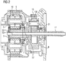
- FIG 2 shows the invention in detail.
- the invention enables sensors to be operated on the planet carrier by means of electronics. Sensors are placed on the planet carrier 5 of the first stage 11 ( FIG. 1 ) and the planet carrier 8 of the second stage 12 ( FIG. 1 ) Are arranged. In particular, through the arrangement of the sensors according to the invention, each individual planet gear 10 of the first stage 11 ( FIG. 1 ) and subsequent levels 12 ( FIG. 1 ) etc. are continuously monitored during operation. Wear can be detected by detecting the oil pressure and / or the vibrations of the planet gears 10 rotating around the sun shaft 6, ie directly at the location where the wear occurs.
- the electronics supply one or more sensors with energy wirelessly or contactlessly. It is possible that the sensors of the first planetary gear stage 11 ( FIG.
- the electronics of the sensors in the first planetary gear stage 11 ( FIG. 1 ) can be done by wire.
- the electronics can consist of first electronics 50, for example a customer interface in the first coordinate system, and second electronics 60, for example a transmitting and receiving unit for the sensors. This is arranged in the second coordinate system.
- the customer interface is arranged on the planet carrier 5.
- a digital interface 53 ( FIG 3 ) provided which data via a wireless connection from one or receives several sensors, one or more sensors in the second or subsequent rotating planetary gear stage 12 ( FIG. 1 ) can be arranged.
- Access to the second planetary gear stage 12 takes place wirelessly or via radio for both the energy and the data.
- the sun shaft 6 is accessible via the rotor hub. It is therefore possible to reach the electronics at this location.
- the radio electronics can also be reached in this way since, according to the invention, they are located on the end face of the sun shaft 6 ( FIG. 1 ) of the first planetary gear stage 11 ( FIG. 1 ) is mounted. This location can be easily reached by disassembling the pitch tube cover 3 in the planet carrier 5. This makes it easy to replace the electronics in the event of service and during the lifetime of the system, such as a wind turbine.
- the energy e.g. a 25 kHz connection can be transmitted via an inductive or capacitive coupling.
- data from the sensors can be transmitted via a 2.4 GHz radio connection.
- These data can also be output not only by radio, but also by modulating the coupling factor.
- an RFID-based (Radio Frequency Identification) or SAW-based (Surface Acoustic Wave) sensor module would also be available conceivable.
- the module is supplied with energy or the interrogation signal by the RFID / SAW reader and its antenna, which also enables measurement data transmission. Because of the comparatively low expenditure on hardware, such modules are advantageous and inexpensive.
- the planet carrier 5 rotates slowly with the rotor blades.
- the necessary lines energy supply, sensor data, etc.
- a rotor hub is always supplied with energy and data, since the pitch tube drives for adjusting the blades require this.
- the electronics can be replaced or serviced through the existing maintenance entry.
- FIG 3 shows the transmission of the sensor data.
- a wireless interface is required from the fastest intermediate speed stage to the non-moving digital interface 53.
- this wireless measurement data transmission from the intermediate stage to the digital interface 53 is shown by an arrow 54.
- the digital interface 53 which is arranged on the first stage (hereinafter also referred to as low speed stage), is connected to an external data processing system (not shown) using a data transmission cable (not shown).
- the sensors are connected to second electronics 60 in the second coordinate system.
- the second electronics 60 is designed with antennas as a transmitting and receiving unit for data and energy.
- the measurement data are transmitted to the digital interface 53 in a buffered manner by radio. By arranging the antennas appropriately, it is possible for each revolution to have radio contact with an antenna only for a specific interval.
- the buffered measurement data are then transmitted in this interval.
- a time stamp is also transmitted.
- the angle of rotation speed and later also the angle of rotation offset between, for example, the first and second stage can be determined over a specific integration period.
- This offset is due to elastic shaft torsion and causes elastic deformation of the teeth of the gears. It represents the current torque. The more sensors or antenna pairs are provided, the more precisely the torque can be determined.
- the figure shows a structure of the contactless energy supply in an axial construction.
- the non-contact energy supply in a radial construction on the planet carrier of the subsequent planetary gear stages.
- the monitoring of operating parameters in the transmission such as Temperature of bearings (e.g. with the help of PT100 elements), vibrations (vibration monitoring with acceleration sensors, e.g. based on the piezo effect), oil pressure in the oil supply lines that are intended for the lubrication of rotating components, oil levels, etc., cause difficulties because A wired connection between the sensors and a receiving unit in the coordinate system of the nacelle is only possible for a few sensors due to the many different rotating coordinate systems. Sensors that are arranged in one of the rotating coordinate systems must be connected to a receiving unit in the coordinate system of the nacelle via a wireless connection.
- the invention makes it possible to measure measurable physical quantities (for example vibration, acceleration, temperature, oil pressure, etc.) of each stage of a planetary gear set under difficult environmental conditions (for example oil, temperature, rotational movement, etc.). Because of the invention, an energy supply of the sensors on the rotating shafts as well as a communication connection of the sensors on each planetary gear stage is now possible.
- measurable physical quantities for example vibration, acceleration, temperature, oil pressure, etc.
- electronics transmit energy wirelessly or contactlessly to one or more sensors.
- Data is also transmitted from the one or more sensors to a digital interface 53 via a wireless connection, the one or more sensors being arranged in the second rotating coordinate system.
- a radio energy transmission on the rotating part is used for the speed determination and the speed-dependent sampling rate (sample rate).
- the speed signal is given outside and can be used by sensors for data acquisition.
- the information can be output by radio or by modulation of the coupling factor.
Landscapes
- Engineering & Computer Science (AREA)
- General Engineering & Computer Science (AREA)
- Mechanical Engineering (AREA)
- Computer Networks & Wireless Communication (AREA)
- Physics & Mathematics (AREA)
- General Physics & Mathematics (AREA)
- Life Sciences & Earth Sciences (AREA)
- Sustainable Development (AREA)
- Sustainable Energy (AREA)
- Chemical & Material Sciences (AREA)
- Combustion & Propulsion (AREA)
- Arrangements For Transmission Of Measured Signals (AREA)
- Wind Motors (AREA)
- Testing Of Devices, Machine Parts, Or Other Structures Thereof (AREA)
- Retarders (AREA)
Claims (16)
- Système de mesure pour détecter des grandeurs sur des porte-satellites d'un train (1) planétaire, comprenant au moins plusieurs étages (11, 12) de roue satellite, dans lequel au moins chaque étage (11, 12) de roue satellite comprend, respectivement, au moins une roue (6, 162) solaire, au moins, respectivement, une roue (15, 19) à denture intérieure, ainsi qu'au moins, respectivement, une roue (10, 130) satellite, qui est reliée à la roue (6, 162) solaire respective et à la roue (15, 19) à denture intérieure respective par un engrènement de dents et, respectivement, un porte-satellite (5, 8), qui est associé à la au moins une roue (10, 130) satellite et qui est solidaire en rotation de la au moins une roue (10, 130) satellite, dans lequel au moins un premier capteur, ayant au moins une borne d'alimentation du premier capteur en énergie électrique, est, pour la détection des grandeurs de la roue (10, 130) planétaire associée, monté sur au moins l'un des porte-satellites (5, 8) sur au moins l'un des étages (11, 12) de roue satellite et dans lequel le train (1) planétaire a une électronique, par laquelle le au moins un premier capteur peut être alimenté en énergie électrique, et dans lequel le au moins un étage (11, 12) de roue satellite peut être choisi parmi chacun des étages (11, 12) de roue satellite présents,
caractérisé en ce que l'électronique comprend une première électronique (50) et une deuxième électronique (60), la première électronique (50) étant disposée sur le premier porte-satellite (5) d'un premier étage (11) satellite et la deuxième électronique étant disposée du côté frontal sur la première roue (6) solaire du premier étage (11) de roue satellite. - Système de mesure suivant la revendication 1,
caractérisé en ce que
l'électronique alimente en énergie le au moins un premier capteur sans contact ou sans fil. - Système de mesure suivant la revendication 1 ou 2,
caractérisé en ce que
le au moins un étage (11, 12) de roue satellite comprend plusieurs roues satellites et il peut être réalisé, par le au moins un premier capteur, un contrôle de toutes les roues satellites. - Système de mesure suivant l'une des revendications précédentes,
caractérisé en ce qu'
il est prévu plusieurs capteurs et l'électronique alimente en énergie, sans contact ou sans fil, au moins les capteurs, qui ne sont pas disposés sur le premier porte-satellite (5) du premier étage (11) de roue satellite. - Système de mesure suivant l'une des revendications précédentes 4,
caractérisé en ce qu'
au moins le premier étage (11) de roue satellite a au moins un deuxième capteur, une deuxième ligne électrique de liaison est prévue de l'électronique au deuxième capteur du premier étage (11) de roue satellite pour alimenter en énergie le deuxième capteur du premier étage (11) de roue satellite. - Système de mesure suivant l'une des revendications 1 à 5,
caractérisé en ce que
la première roue (6) solaire du premier étage (11) satellite est constituée, au moins en partie, sous la forme d'un arbre creux et la deuxième électronique (60) a une première ligne électrique de liaison passant dans cet arbre creux. - Système de mesure suivant l'une des revendications précédentes,
caractérisé en ce qu'
il est prévu une interface (53) numérique pour la transmission des données à une installation de traitement de données. - Système de mesure suivant la revendication 7,
caractérisé en ce que
l'interface numérique est montée du côté frontal sur le premier porte-satellite (5) du premier étage (11) de roue satellite. - Système de mesure suivant l'une des revendications 7 ou 8,
caractérisé en que
la transmission de données s'effectue sans contact ou sans fil du au moins un premier capteur à l'interface (53) numérique. - Système de mesure suivant l'une des revendications précédentes lorsqu'elle dépend de la revendication 5,
caractérisé en ce qu'
au moins le premier étage (11) de roue satellite a, sur le premier porte-satellite, le deuxième capteur et la transmission de données du deuxième capteur à l'interface (53) numérique s'effectue par un deuxième câble de transmission de données. - Système de mesure suivant la revendication 9,
caractérisé en ce que
la transmission de données sans fil s'effectue au moyen de la radio ou de manière optique. - Système de mesure suivant l'une des revendications 9 ou 11 précédentes,
caractérisé en ce que
la transmission d'énergie s'effectue par un couplage ayant un facteur de couplage et la transmission de données sans fil s'effectue par émission de la modulation du facteur de couplage. - Système de mesure suivant l'une des revendications 7 à 12 précédentes,
caractérisé en ce que
la transmission de données s'effectue de manière tamponnée du au moins un premier capteur à l'interface (53) numérique. - Système de mesure suivant l'une des revendications précédentes,
caractérisé en ce que
plusieurs capteurs sont montés sur le au moins un porte-satellite (5, 8). - Procédé de mesure pour détecter des grandeurs sur des porte-satellites d'un train (1) planétaire, comprenant au moins plusieurs étages (11, 12) de roue satellite, dans lequel au moins chaque étage (11, 12) de roue satellite comprend, respectivement, au moins une roue (6, 162) solaire, au moins, respectivement, une roue (15, 19) à denture intérieure, ainsi qu'au moins, respectivement, une roue (10, 130) satellite, qui est reliée à la roue (6, 162) solaire respective et à la roue (15, 19) à denture intérieure respective par un engrènement de dents et, respectivement, un porte-satellite (5, 8), qui est associé à la au moins une roue (10, 130) satellite et qui est solidaire en rotation de la au moins une roue (10, 130) satellite, dans lequel on rend possible, par au moins un premier capteur mis sur au moins l'un des porte-satellites sur au moins l'un des étages (11, 12) de roue satellite et qui a au moins une borne d'alimentation de premier capteur en énergie électrique, une détection de grandeurs de la roue (10, 130) satellite associée et dans lequel, par une électronique du train (11) planétaire, on alimente le au moins un premier capteur en énergie électrique et dans lequel le au moins un étage (11, 12) de roue satellite peut être choisi dans chacun des étages (11, 12) de roue satellite présent,
dans lequel on transmet l'énergie électrique sans fil et la transmission d'énergie sans fil par un couplage capacitif ou par un couplage inductif en ayant un facteur de couplage,
caractérisé en ce qu'une transmission de données de capteurs s'effectue par une interface (53) numérique et la transmission de données s'effectue par modulation du facteur de couplage. - Procédé de mesure suivant la revendication 15, que l'on effectue par un système de mesure suivant l'une des revendications 1 à 14 précédentes.
Applications Claiming Priority (2)
| Application Number | Priority Date | Filing Date | Title |
|---|---|---|---|
| DE102015002619 | 2015-03-03 | ||
| PCT/EP2016/054313 WO2016139199A1 (fr) | 2015-03-03 | 2016-03-01 | Système et procédé de mesure permettant de détecter des grandeurs sur les porte-satellites d'un train planétaire |
Publications (2)
| Publication Number | Publication Date |
|---|---|
| EP3243015A1 EP3243015A1 (fr) | 2017-11-15 |
| EP3243015B1 true EP3243015B1 (fr) | 2020-02-19 |
Family
ID=55527531
Family Applications (1)
| Application Number | Title | Priority Date | Filing Date |
|---|---|---|---|
| EP16709733.6A Active EP3243015B1 (fr) | 2015-03-03 | 2016-03-01 | Système et procédé de mesure permettant de détecter des grandeurs sur les porte-satellites d'un train planétaire |
Country Status (6)
| Country | Link |
|---|---|
| US (1) | US10309516B2 (fr) |
| EP (1) | EP3243015B1 (fr) |
| CN (1) | CN107429818B (fr) |
| BR (1) | BR112017018624B1 (fr) |
| ES (1) | ES2785376T3 (fr) |
| WO (1) | WO2016139199A1 (fr) |
Families Citing this family (9)
| Publication number | Priority date | Publication date | Assignee | Title |
|---|---|---|---|---|
| DE102016202176A1 (de) * | 2016-02-12 | 2017-08-17 | Bestsens Ag | Verzahnungsanordnung und Verfahren zum Bestimmen von Eigenschaften einer Verzahnungsanordnung |
| WO2018077373A1 (fr) * | 2016-10-24 | 2018-05-03 | Siemens Aktiengesellschaft | Dispositif de détection de grandeur d'état, transmission comprenant un dispositif de détection de grandeur d'état, centrale électrique comprenant une transmission de ce type et procédé de surveillance d'une transmission de ce type ou d'une centrale électrique de ce type |
| DE102018200933A1 (de) * | 2018-01-22 | 2019-07-25 | Aktiebolaget Skf | Planetengetriebeanordnung |
| CN110739798B (zh) * | 2018-07-18 | 2020-11-10 | 六环传动(西安)科技有限公司 | 能够实现全闭环控制的行星减速电机及关节机器人 |
| DE102019209948A1 (de) * | 2019-07-05 | 2021-01-07 | Zf Friedrichshafen Ag | Übertragung von Energie und Daten mittels eines Öldurchführungsrings |
| CN110470471B (zh) * | 2019-08-09 | 2021-03-09 | 南京航空航天大学 | 一种液压驱动行星架静态试验台 |
| USD973740S1 (en) * | 2019-10-09 | 2022-12-27 | Flender Gmbh | Gear |
| US11780610B2 (en) * | 2019-11-07 | 2023-10-10 | Ge Aviation Systems Limited | Monitoring of a revolving component employing time-synchronized multiple detectors |
| IT202200004868A1 (it) * | 2022-03-14 | 2023-09-14 | Milano Politecnico | Apparato sensore per corpi in rotazione relativa |
Family Cites Families (25)
| Publication number | Priority date | Publication date | Assignee | Title |
|---|---|---|---|---|
| EP1588138A1 (fr) * | 2003-01-24 | 2005-10-26 | The Commonwealth of Australia as represented by the Defence Science and Technology Organisation of the Department of Defence | Moyenne synchrone des vibrations d'un train epicycloidal |
| WO2007085259A1 (fr) * | 2006-01-25 | 2007-08-02 | Vestas Wind Systems A/S | Éolienne comprenant au moins une boîte d'engrenage et un train épicycloïdal |
| US7970556B2 (en) * | 2009-01-30 | 2011-06-28 | General Electric | System and method for monitoring the condition of a gear assembly |
| DE102009021238A1 (de) | 2009-05-14 | 2010-11-18 | Siemens Aktiengesellschaft | Verfahren zur Identifizierung von Verschmutzung und /oder Betauung von Bauelementen eines Spannungszwischenkreis-Umrichters |
| DE102009034832A1 (de) | 2009-07-27 | 2011-02-03 | Winergy Ag | Getriebe für industrielle Anwendungen oder Windkraftanlagen |
| FI20105179A7 (fi) | 2010-02-24 | 2011-08-25 | Espotel Oy | Valvontajärjestelmä |
| CN102782458B (zh) | 2010-03-01 | 2016-03-23 | 西门子公司 | 具有能量转换器的轴承电流传感器装置 |
| WO2011107110A1 (fr) | 2010-03-01 | 2011-09-09 | Siemens Aktiengesellschaft | Procédé et dispositif de détection précoce de dégâts dans un palier |
| ES2732884T3 (es) | 2010-03-01 | 2019-11-26 | Siemens Ag | Procedimiento para vigilar la función de puesta a tierra y utilización del procedimiento |
| DE102010034749A1 (de) * | 2010-08-19 | 2012-02-23 | Schaeffler Technologies Gmbh & Co. Kg | Vorrichtung zur Überwachung eines rotierenden Maschinenteils |
| US8568099B2 (en) * | 2010-12-17 | 2013-10-29 | Vestas Wind Systems A/S | Apparatus for harvesting energy from a gearbox to power an electrical device and related methods |
| WO2013023699A1 (fr) | 2011-08-18 | 2013-02-21 | Siemens Aktiengesellschaft | Dispositif pour déterminer un couple et procédé de mesure correspondant |
| CN103748477B (zh) | 2011-08-18 | 2016-03-16 | 西门子公司 | 用于设备组成部分的状态监控的装置和方法 |
| EP2594789B1 (fr) | 2011-11-17 | 2014-04-30 | Siemens Aktiengesellschaft | Engrenage pour une éolienne |
| DE102012210191A1 (de) | 2011-12-14 | 2013-06-20 | Winergy Ag | Prüfvorrichtung und Verfahren zum Prüfen einer ersten und/oder einer zweiten elektrischen Maschine |
| RU2578513C1 (ru) | 2012-04-12 | 2016-03-27 | Сименс Акциенгезелльшафт | Сенсорный элемент с датчиком акустической эмиссии |
| EP2805072A1 (fr) | 2012-04-19 | 2014-11-26 | Siemens Aktiengesellschaft | Procédé et dispositif de mesure pour contrôler des états de fonctionnement d'un palier lisse |
| EP2844973B1 (fr) | 2012-05-02 | 2016-04-27 | Siemens Aktiengesellschaft | Procédé de surveillance de déterioration d'un arbre |
| US20130303322A1 (en) * | 2012-05-08 | 2013-11-14 | Robert C. Kennedy | Variable Speed Drive System |
| WO2014044302A1 (fr) | 2012-09-19 | 2014-03-27 | Siemens Aktiengesellschaft | Ensemble palier et procédé permettant de déterminer une zone de charge d'un palier |
| US20160132616A1 (en) | 2013-06-10 | 2016-05-12 | Siemens Aktiengesellschaft | Planning a power distribution network |
| CN103711875B (zh) | 2014-01-06 | 2016-04-13 | 国电联合动力技术有限公司 | 一种风力发电机组行星齿轮偏载的监测系统及方法 |
| EP2933483A1 (fr) * | 2014-04-15 | 2015-10-21 | Siemens Aktiengesellschaft | Système d'entraînement d'une éolienne |
| ES2689924T3 (es) | 2014-08-29 | 2018-11-16 | Siemens Aktiengesellschaft | Aerogenerador con un tren motriz |
| EP2990644A1 (fr) | 2014-08-29 | 2016-03-02 | Siemens Aktiengesellschaft | Éolienne |
-
2016
- 2016-03-01 BR BR112017018624-1A patent/BR112017018624B1/pt not_active IP Right Cessation
- 2016-03-01 US US15/554,377 patent/US10309516B2/en active Active
- 2016-03-01 EP EP16709733.6A patent/EP3243015B1/fr active Active
- 2016-03-01 WO PCT/EP2016/054313 patent/WO2016139199A1/fr not_active Ceased
- 2016-03-01 ES ES16709733T patent/ES2785376T3/es active Active
- 2016-03-01 CN CN201680013019.7A patent/CN107429818B/zh active Active
Non-Patent Citations (1)
| Title |
|---|
| None * |
Also Published As
| Publication number | Publication date |
|---|---|
| BR112017018624A2 (pt) | 2018-04-17 |
| CN107429818A (zh) | 2017-12-01 |
| US10309516B2 (en) | 2019-06-04 |
| US20180038471A1 (en) | 2018-02-08 |
| BR112017018624B1 (pt) | 2023-01-24 |
| CN107429818B (zh) | 2020-06-26 |
| WO2016139199A1 (fr) | 2016-09-09 |
| EP3243015A1 (fr) | 2017-11-15 |
| ES2785376T3 (es) | 2020-10-06 |
Similar Documents
| Publication | Publication Date | Title |
|---|---|---|
| EP3243015B1 (fr) | Système et procédé de mesure permettant de détecter des grandeurs sur les porte-satellites d'un train planétaire | |
| EP2843778B1 (fr) | Unité de bague collectrice et procédé de surveillance de l'état d'une unité de bague collectrice | |
| EP3020965A1 (fr) | Turbine éolienne, utilisation et méthode | |
| EP3268635B1 (fr) | Train épicycloïdal | |
| DE102016204736A1 (de) | Vorrichtung zur Zustandsüberwachung | |
| EP3472459B1 (fr) | Procédé de surveillance d'un réglage de pales de rotor | |
| EP3994803B1 (fr) | Transmission d'énergie et de données au moyen d'une bague de passage d'huile | |
| WO2020064504A1 (fr) | Corps de roulement équipé d'un capteur et destiné à être utilisé dans un palier à roulement | |
| DE102012015357B4 (de) | Nichtschaltbare Kupplung mit Drehmomentüberwachung | |
| EP4065853B1 (fr) | Ensemble palier | |
| WO2013029955A1 (fr) | Changeur de prises en charge à engrenage à vis sans fin | |
| DE102019208713A1 (de) | Gelenkwelle | |
| DE102018211848B3 (de) | Elektromotor, Ventilator und System bestehend aus Elektromotor und Auswerteeinheit | |
| DE10117405B4 (de) | Adapter und System von Adaptern | |
| DE102010021642A1 (de) | Übertragungsvorrichtung | |
| EP2754163B1 (fr) | Entraînement motorisé pour actionner un changeur de prises en charge | |
| WO2018138198A1 (fr) | Unité d'entraînement électrique avec surveillance de besoin de maintenance intelligente | |
| EP3786591B1 (fr) | Unité de capteur et boîte de vitesses dotée d'au moins une telle unité de capteur | |
| DE8511143U1 (de) | Meßnabe zur Drehmoment- und Drehzahlmessung an umlaufenden Maschinenteilen | |
| DE102019108981B4 (de) | Radsatzlager für ein Schienenfahrzeug und Verfahren zum Betrieb einer Sensorik eines Radsatzlagers | |
| EP3865705B1 (fr) | Éolienne, ainsi que procédé de surveillance d'un entrainement azimutal de l'éolienne | |
| DE102013207405A1 (de) | Doppeltwirkender Generator | |
| DE102017106311A1 (de) | Wechselflansch mit Sensorik für ein Getriebe | |
| DE102017118771A1 (de) | Abtriebsstation für die Betätigung einer Klappe an einem Flugzeugflügel und Flugzeug mit solchen Abtriebsstationen | |
| EP3514552B1 (fr) | Dispositif capteur, agencement de capteur, système de capteur ainsi qu'utilisation du dispositif capteur et de l'agencement de capteur |
Legal Events
| Date | Code | Title | Description |
|---|---|---|---|
| STAA | Information on the status of an ep patent application or granted ep patent |
Free format text: STATUS: THE INTERNATIONAL PUBLICATION HAS BEEN MADE |
|
| PUAI | Public reference made under article 153(3) epc to a published international application that has entered the european phase |
Free format text: ORIGINAL CODE: 0009012 |
|
| STAA | Information on the status of an ep patent application or granted ep patent |
Free format text: STATUS: REQUEST FOR EXAMINATION WAS MADE |
|
| 17P | Request for examination filed |
Effective date: 20170809 |
|
| AK | Designated contracting states |
Kind code of ref document: A1 Designated state(s): AL AT BE BG CH CY CZ DE DK EE ES FI FR GB GR HR HU IE IS IT LI LT LU LV MC MK MT NL NO PL PT RO RS SE SI SK SM TR |
|
| AX | Request for extension of the european patent |
Extension state: BA ME |
|
| RIN1 | Information on inventor provided before grant (corrected) |
Inventor name: VON DOSKY, STEFAN Inventor name: KECK, REINHOLD Inventor name: HASSEL, JOERG Inventor name: CAMMINADI, JULIA Inventor name: DEICKE, MATTHIAS Inventor name: KLOS, HANS-HENNING |
|
| RAP1 | Party data changed (applicant data changed or rights of an application transferred) |
Owner name: FLENDER GMBH |
|
| DAV | Request for validation of the european patent (deleted) | ||
| DAX | Request for extension of the european patent (deleted) | ||
| STAA | Information on the status of an ep patent application or granted ep patent |
Free format text: STATUS: EXAMINATION IS IN PROGRESS |
|
| 17Q | First examination report despatched |
Effective date: 20190124 |
|
| GRAP | Despatch of communication of intention to grant a patent |
Free format text: ORIGINAL CODE: EPIDOSNIGR1 |
|
| STAA | Information on the status of an ep patent application or granted ep patent |
Free format text: STATUS: GRANT OF PATENT IS INTENDED |
|
| RIC1 | Information provided on ipc code assigned before grant |
Ipc: F03D 15/00 20160101ALN20190829BHEP Ipc: H04Q 9/00 20060101ALI20190829BHEP Ipc: F03D 17/00 20160101ALI20190829BHEP Ipc: G01M 13/021 20190101ALI20190829BHEP Ipc: F16H 1/46 20060101ALN20190829BHEP Ipc: F16H 57/01 20120101AFI20190829BHEP |
|
| INTG | Intention to grant announced |
Effective date: 20190930 |
|
| GRAS | Grant fee paid |
Free format text: ORIGINAL CODE: EPIDOSNIGR3 |
|
| GRAA | (expected) grant |
Free format text: ORIGINAL CODE: 0009210 |
|
| STAA | Information on the status of an ep patent application or granted ep patent |
Free format text: STATUS: THE PATENT HAS BEEN GRANTED |
|
| AK | Designated contracting states |
Kind code of ref document: B1 Designated state(s): AL AT BE BG CH CY CZ DE DK EE ES FI FR GB GR HR HU IE IS IT LI LT LU LV MC MK MT NL NO PL PT RO RS SE SI SK SM TR |
|
| REG | Reference to a national code |
Ref country code: CH Ref legal event code: EP |
|
| REG | Reference to a national code |
Ref country code: DE Ref legal event code: R096 Ref document number: 502016008793 Country of ref document: DE |
|
| REG | Reference to a national code |
Ref country code: AT Ref legal event code: REF Ref document number: 1235330 Country of ref document: AT Kind code of ref document: T Effective date: 20200315 |
|
| REG | Reference to a national code |
Ref country code: IE Ref legal event code: FG4D Free format text: LANGUAGE OF EP DOCUMENT: GERMAN |
|
| REG | Reference to a national code |
Ref country code: SE Ref legal event code: TRGR |
|
| REG | Reference to a national code |
Ref country code: NL Ref legal event code: MP Effective date: 20200219 |
|
| PG25 | Lapsed in a contracting state [announced via postgrant information from national office to epo] |
Ref country code: FI Free format text: LAPSE BECAUSE OF FAILURE TO SUBMIT A TRANSLATION OF THE DESCRIPTION OR TO PAY THE FEE WITHIN THE PRESCRIBED TIME-LIMIT Effective date: 20200219 Ref country code: NO Free format text: LAPSE BECAUSE OF FAILURE TO SUBMIT A TRANSLATION OF THE DESCRIPTION OR TO PAY THE FEE WITHIN THE PRESCRIBED TIME-LIMIT Effective date: 20200519 Ref country code: RS Free format text: LAPSE BECAUSE OF FAILURE TO SUBMIT A TRANSLATION OF THE DESCRIPTION OR TO PAY THE FEE WITHIN THE PRESCRIBED TIME-LIMIT Effective date: 20200219 |
|
| REG | Reference to a national code |
Ref country code: LT Ref legal event code: MG4D |
|
| PG25 | Lapsed in a contracting state [announced via postgrant information from national office to epo] |
Ref country code: IS Free format text: LAPSE BECAUSE OF FAILURE TO SUBMIT A TRANSLATION OF THE DESCRIPTION OR TO PAY THE FEE WITHIN THE PRESCRIBED TIME-LIMIT Effective date: 20200619 Ref country code: HR Free format text: LAPSE BECAUSE OF FAILURE TO SUBMIT A TRANSLATION OF THE DESCRIPTION OR TO PAY THE FEE WITHIN THE PRESCRIBED TIME-LIMIT Effective date: 20200219 Ref country code: LV Free format text: LAPSE BECAUSE OF FAILURE TO SUBMIT A TRANSLATION OF THE DESCRIPTION OR TO PAY THE FEE WITHIN THE PRESCRIBED TIME-LIMIT Effective date: 20200219 Ref country code: GR Free format text: LAPSE BECAUSE OF FAILURE TO SUBMIT A TRANSLATION OF THE DESCRIPTION OR TO PAY THE FEE WITHIN THE PRESCRIBED TIME-LIMIT Effective date: 20200520 Ref country code: BG Free format text: LAPSE BECAUSE OF FAILURE TO SUBMIT A TRANSLATION OF THE DESCRIPTION OR TO PAY THE FEE WITHIN THE PRESCRIBED TIME-LIMIT Effective date: 20200519 |
|
| PG25 | Lapsed in a contracting state [announced via postgrant information from national office to epo] |
Ref country code: NL Free format text: LAPSE BECAUSE OF FAILURE TO SUBMIT A TRANSLATION OF THE DESCRIPTION OR TO PAY THE FEE WITHIN THE PRESCRIBED TIME-LIMIT Effective date: 20200219 |
|
| REG | Reference to a national code |
Ref country code: ES Ref legal event code: FG2A Ref document number: 2785376 Country of ref document: ES Kind code of ref document: T3 Effective date: 20201006 |
|
| PG25 | Lapsed in a contracting state [announced via postgrant information from national office to epo] |
Ref country code: CZ Free format text: LAPSE BECAUSE OF FAILURE TO SUBMIT A TRANSLATION OF THE DESCRIPTION OR TO PAY THE FEE WITHIN THE PRESCRIBED TIME-LIMIT Effective date: 20200219 Ref country code: RO Free format text: LAPSE BECAUSE OF FAILURE TO SUBMIT A TRANSLATION OF THE DESCRIPTION OR TO PAY THE FEE WITHIN THE PRESCRIBED TIME-LIMIT Effective date: 20200219 Ref country code: SM Free format text: LAPSE BECAUSE OF FAILURE TO SUBMIT A TRANSLATION OF THE DESCRIPTION OR TO PAY THE FEE WITHIN THE PRESCRIBED TIME-LIMIT Effective date: 20200219 Ref country code: LT Free format text: LAPSE BECAUSE OF FAILURE TO SUBMIT A TRANSLATION OF THE DESCRIPTION OR TO PAY THE FEE WITHIN THE PRESCRIBED TIME-LIMIT Effective date: 20200219 Ref country code: EE Free format text: LAPSE BECAUSE OF FAILURE TO SUBMIT A TRANSLATION OF THE DESCRIPTION OR TO PAY THE FEE WITHIN THE PRESCRIBED TIME-LIMIT Effective date: 20200219 Ref country code: DK Free format text: LAPSE BECAUSE OF FAILURE TO SUBMIT A TRANSLATION OF THE DESCRIPTION OR TO PAY THE FEE WITHIN THE PRESCRIBED TIME-LIMIT Effective date: 20200219 Ref country code: PT Free format text: LAPSE BECAUSE OF FAILURE TO SUBMIT A TRANSLATION OF THE DESCRIPTION OR TO PAY THE FEE WITHIN THE PRESCRIBED TIME-LIMIT Effective date: 20200712 Ref country code: SK Free format text: LAPSE BECAUSE OF FAILURE TO SUBMIT A TRANSLATION OF THE DESCRIPTION OR TO PAY THE FEE WITHIN THE PRESCRIBED TIME-LIMIT Effective date: 20200219 |
|
| REG | Reference to a national code |
Ref country code: CH Ref legal event code: PL |
|
| REG | Reference to a national code |
Ref country code: DE Ref legal event code: R097 Ref document number: 502016008793 Country of ref document: DE |
|
| PG25 | Lapsed in a contracting state [announced via postgrant information from national office to epo] |
Ref country code: MC Free format text: LAPSE BECAUSE OF FAILURE TO SUBMIT A TRANSLATION OF THE DESCRIPTION OR TO PAY THE FEE WITHIN THE PRESCRIBED TIME-LIMIT Effective date: 20200219 |
|
| REG | Reference to a national code |
Ref country code: BE Ref legal event code: MM Effective date: 20200331 |
|
| PLBE | No opposition filed within time limit |
Free format text: ORIGINAL CODE: 0009261 |
|
| STAA | Information on the status of an ep patent application or granted ep patent |
Free format text: STATUS: NO OPPOSITION FILED WITHIN TIME LIMIT |
|
| PG25 | Lapsed in a contracting state [announced via postgrant information from national office to epo] |
Ref country code: LU Free format text: LAPSE BECAUSE OF NON-PAYMENT OF DUE FEES Effective date: 20200301 |
|
| 26N | No opposition filed |
Effective date: 20201120 |
|
| PG25 | Lapsed in a contracting state [announced via postgrant information from national office to epo] |
Ref country code: LI Free format text: LAPSE BECAUSE OF NON-PAYMENT OF DUE FEES Effective date: 20200331 Ref country code: CH Free format text: LAPSE BECAUSE OF NON-PAYMENT OF DUE FEES Effective date: 20200331 Ref country code: IE Free format text: LAPSE BECAUSE OF NON-PAYMENT OF DUE FEES Effective date: 20200301 |
|
| PG25 | Lapsed in a contracting state [announced via postgrant information from national office to epo] |
Ref country code: PL Free format text: LAPSE BECAUSE OF FAILURE TO SUBMIT A TRANSLATION OF THE DESCRIPTION OR TO PAY THE FEE WITHIN THE PRESCRIBED TIME-LIMIT Effective date: 20200219 Ref country code: BE Free format text: LAPSE BECAUSE OF NON-PAYMENT OF DUE FEES Effective date: 20200331 Ref country code: SI Free format text: LAPSE BECAUSE OF FAILURE TO SUBMIT A TRANSLATION OF THE DESCRIPTION OR TO PAY THE FEE WITHIN THE PRESCRIBED TIME-LIMIT Effective date: 20200219 |
|
| REG | Reference to a national code |
Ref country code: AT Ref legal event code: MM01 Ref document number: 1235330 Country of ref document: AT Kind code of ref document: T Effective date: 20210301 |
|
| PG25 | Lapsed in a contracting state [announced via postgrant information from national office to epo] |
Ref country code: TR Free format text: LAPSE BECAUSE OF FAILURE TO SUBMIT A TRANSLATION OF THE DESCRIPTION OR TO PAY THE FEE WITHIN THE PRESCRIBED TIME-LIMIT Effective date: 20200219 Ref country code: MT Free format text: LAPSE BECAUSE OF FAILURE TO SUBMIT A TRANSLATION OF THE DESCRIPTION OR TO PAY THE FEE WITHIN THE PRESCRIBED TIME-LIMIT Effective date: 20200219 Ref country code: CY Free format text: LAPSE BECAUSE OF FAILURE TO SUBMIT A TRANSLATION OF THE DESCRIPTION OR TO PAY THE FEE WITHIN THE PRESCRIBED TIME-LIMIT Effective date: 20200219 |
|
| PGFP | Annual fee paid to national office [announced via postgrant information from national office to epo] |
Ref country code: SE Payment date: 20220321 Year of fee payment: 7 Ref country code: IT Payment date: 20220322 Year of fee payment: 7 |
|
| PG25 | Lapsed in a contracting state [announced via postgrant information from national office to epo] |
Ref country code: MK Free format text: LAPSE BECAUSE OF FAILURE TO SUBMIT A TRANSLATION OF THE DESCRIPTION OR TO PAY THE FEE WITHIN THE PRESCRIBED TIME-LIMIT Effective date: 20200219 Ref country code: AL Free format text: LAPSE BECAUSE OF FAILURE TO SUBMIT A TRANSLATION OF THE DESCRIPTION OR TO PAY THE FEE WITHIN THE PRESCRIBED TIME-LIMIT Effective date: 20200219 |
|
| PG25 | Lapsed in a contracting state [announced via postgrant information from national office to epo] |
Ref country code: AT Free format text: LAPSE BECAUSE OF NON-PAYMENT OF DUE FEES Effective date: 20210301 |
|
| PGFP | Annual fee paid to national office [announced via postgrant information from national office to epo] |
Ref country code: FR Payment date: 20230324 Year of fee payment: 8 |
|
| PGFP | Annual fee paid to national office [announced via postgrant information from national office to epo] |
Ref country code: GB Payment date: 20230322 Year of fee payment: 8 |
|
| REG | Reference to a national code |
Ref country code: SE Ref legal event code: EUG |
|
| PG25 | Lapsed in a contracting state [announced via postgrant information from national office to epo] |
Ref country code: SE Free format text: LAPSE BECAUSE OF NON-PAYMENT OF DUE FEES Effective date: 20230302 |
|
| PG25 | Lapsed in a contracting state [announced via postgrant information from national office to epo] |
Ref country code: IT Free format text: LAPSE BECAUSE OF NON-PAYMENT OF DUE FEES Effective date: 20230301 |
|
| GBPC | Gb: european patent ceased through non-payment of renewal fee |
Effective date: 20240301 |
|
| PG25 | Lapsed in a contracting state [announced via postgrant information from national office to epo] |
Ref country code: GB Free format text: LAPSE BECAUSE OF NON-PAYMENT OF DUE FEES Effective date: 20240301 |
|
| PG25 | Lapsed in a contracting state [announced via postgrant information from national office to epo] |
Ref country code: FR Free format text: LAPSE BECAUSE OF NON-PAYMENT OF DUE FEES Effective date: 20240331 |
|
| PG25 | Lapsed in a contracting state [announced via postgrant information from national office to epo] |
Ref country code: GB Free format text: LAPSE BECAUSE OF NON-PAYMENT OF DUE FEES Effective date: 20240301 Ref country code: FR Free format text: LAPSE BECAUSE OF NON-PAYMENT OF DUE FEES Effective date: 20240331 |
|
| PGFP | Annual fee paid to national office [announced via postgrant information from national office to epo] |
Ref country code: ES Payment date: 20250429 Year of fee payment: 10 |
|
| PGFP | Annual fee paid to national office [announced via postgrant information from national office to epo] |
Ref country code: DE Payment date: 20260325 Year of fee payment: 11 |