EP3244149B1 - Récipient pour produits réfrigérés ayant une partie avant séparée - Google Patents
Récipient pour produits réfrigérés ayant une partie avant séparée Download PDFInfo
- Publication number
- EP3244149B1 EP3244149B1 EP17161403.5A EP17161403A EP3244149B1 EP 3244149 B1 EP3244149 B1 EP 3244149B1 EP 17161403 A EP17161403 A EP 17161403A EP 3244149 B1 EP3244149 B1 EP 3244149B1
- Authority
- EP
- European Patent Office
- Prior art keywords
- container
- refrigerated
- goods
- fastening
- front wall
- Prior art date
- Legal status (The legal status is an assumption and is not a legal conclusion. Google has not performed a legal analysis and makes no representation as to the accuracy of the status listed.)
- Active
Links
Images




Classifications
-
- F—MECHANICAL ENGINEERING; LIGHTING; HEATING; WEAPONS; BLASTING
- F25—REFRIGERATION OR COOLING; COMBINED HEATING AND REFRIGERATION SYSTEMS; HEAT PUMP SYSTEMS; MANUFACTURE OR STORAGE OF ICE; LIQUEFACTION SOLIDIFICATION OF GASES
- F25D—REFRIGERATORS; COLD ROOMS; ICE-BOXES; COOLING OR FREEZING APPARATUS NOT OTHERWISE PROVIDED FOR
- F25D11/00—Self-contained movable devices, e.g. domestic refrigerators
-
- F—MECHANICAL ENGINEERING; LIGHTING; HEATING; WEAPONS; BLASTING
- F25—REFRIGERATION OR COOLING; COMBINED HEATING AND REFRIGERATION SYSTEMS; HEAT PUMP SYSTEMS; MANUFACTURE OR STORAGE OF ICE; LIQUEFACTION SOLIDIFICATION OF GASES
- F25D—REFRIGERATORS; COLD ROOMS; ICE-BOXES; COOLING OR FREEZING APPARATUS NOT OTHERWISE PROVIDED FOR
- F25D25/00—Charging, supporting, and discharging the articles to be cooled
- F25D25/02—Charging, supporting, and discharging the articles to be cooled by shelves
- F25D25/024—Slidable shelves
- F25D25/025—Drawers
-
- A—HUMAN NECESSITIES
- A47—FURNITURE; DOMESTIC ARTICLES OR APPLIANCES; COFFEE MILLS; SPICE MILLS; SUCTION CLEANERS IN GENERAL
- A47B—TABLES; DESKS; OFFICE FURNITURE; CABINETS; DRAWERS; GENERAL DETAILS OF FURNITURE
- A47B88/00—Drawers for tables, cabinets or like furniture; Guides for drawers
- A47B88/90—Constructional details of drawers
- A47B88/944—Drawers characterised by the front panel
- A47B2088/9441—Drawers characterised by the front panel the front panel being less wide than the drawer
-
- A—HUMAN NECESSITIES
- A47—FURNITURE; DOMESTIC ARTICLES OR APPLIANCES; COFFEE MILLS; SPICE MILLS; SUCTION CLEANERS IN GENERAL
- A47B—TABLES; DESKS; OFFICE FURNITURE; CABINETS; DRAWERS; GENERAL DETAILS OF FURNITURE
- A47B2210/00—General construction of drawers, guides and guide devices
- A47B2210/17—Drawers used in connection with household appliances
- A47B2210/175—Refrigerators or freezers
Definitions
- the invention relates to a refrigerated goods container for a household refrigerating appliance and a household refrigerating appliance with such a refrigerated goods container and a method for mounting a front wall to a refrigerated goods body.
- refrigerated goods containers such as boxes or vegetable compartments.
- refrigerated goods containers are usually made of plastic. Transparent materials are gladly used so that a user can see the refrigerated goods container contents without having to remove the refrigerated goods container from the interior of the household refrigerating appliance. It is known to produce the refrigerated goods in one piece, furthermore, it is also known to form the front walls of the refrigerated goods as a separate component and to connect with the remainingmégut matterer emotions.
- EP 0 962 731 A1 discloses a storage compartment for a refrigerator door with a serving for storing refrigerated goods storage shelf, which is provided at least on its front side opposite the refrigerator door with a retaining board, wherein the retaining board is formed as releasably on the front side content, at least substantially closed area running retaining wall, which at least almost reaches into the parking level of the storage floor.
- US 5,437,503 discloses a container body having a bottom wall, two side walls, a rear wall, and a front wall.
- a container front module closes the front of the container body.
- the container front module comprises a frame, the frame having a rectangular edge with a rectangular cross section formed of a planar front and a rearwardly projecting side.
- the upper front corners of the side walls include upwardly projecting protrusions.
- the projections engage in openings at upper corners of the frame.
- the front portion of the bottom wall of the container body includes a number of small downwardly directed U-shaped protrusions.
- the bottom wall of the frame includes a number of rectangular openings to receive the projections.
- the frame is mounted to the container body by engaging the protrusions in the openings of the frame, and then rotating the frame until the protrusions are fully positioned in the openings of the frame.
- DE 10 2011 017 735 A1 discloses a refrigerated goods for refrigerators, the one Base body, wherein the base body has a bottom surface and a first and second side boundary, wherein the first side boundary is connected to the bottom surface and the second side boundary of the base body is removable, wherein the second side boundary in a mounted state via a snap connection with the first side boundary connected is.
- US 5,921,648 discloses a refrigerated goods container with a container and a separate front. On the outside of the bottom plate of the container a plurality of connecting projections is arranged and a side walls of the container Mausvor- or recesses are arranged. The connecting projections or recesses of the container are connected to corresponding connecting projections or recesses of the front side.
- DE 20 2005 012 342 A1 discloses refrigerated goods container having a base body and serving as a front wall side wall, which is joined to the base body, adjacent to a side edge of the front wall at least partially a tongue and groove connection between the main body and the front wall and a depth direction of the body form-fitting connection forms between the main body and the front wall.
- DE 10 2015 206 860 A1 discloses a household refrigerator with an inner container that limits an interior for receiving food, and having an interior food storage container having a food intake bowl and a lid, wherein the food receiving bowl a destruction-releasably arranged partition wall for dividing the volume the food-receiving shell has in at least two separate sub-volume.
- the invention has for its object to provide a refrigerated goods, which allows a very simple installation and secure attachment of the front wall of a refrigerated goods to adegut constituer emotions, at the same time the refrigerated goods can be made very easily.
- the object is solved by the features of the independent claims. Preferred embodiments are given in the dependent claims.
- a first aspect relates to a refrigerated goods container for a refrigerator with a bottom wall, two side walls, a rear wall, which form adegut actuallyerkorpus, and a separate front wall, which is formed by a sheet-like element, wherein the front wall
- the refrigerated goods container having a plurality of support ribs, and at least one first retaining projection which hold the front wall to thedegut electerkorpus in a use position, and that the support ribs and the at least one first retaining projection are arranged on different major surfaces.
- the refrigerated goods container is preferably a tray or a box.
- the refrigerated goods body i. the rear wall, the two side walls and the bottom wall of the refrigerated goods container, are preferably formed as an integral component.
- thedegut capableerkorpus is made in one piece.
- the front wall is separable or removably attached.
- the two side walls are a left side wall and a right side wall.
- at least one support rib is arranged or provided on each side wall.
- one side wall comprises two, three or four support ribs.
- the support ribs preferably project from the sidewall or protrude from the sidewall.
- the support ribs are arranged on the front edge of the side wall.
- the left side wall and the right side wall may have different number of support ribs.
- the support ribs are arranged in the vicinity of the front edge of the side wall.
- the support ribs are not more than 2 cm, in particular not more than 1 cm, away from the front edge of the side wall.
- the support ribs are preferably arranged on the insides of the side walls.
- the support ribs are directed to the inside of the refrigerated goods.
- the support ribs are integrally formed on the side wall, so that the support ribs are part of theharigut electerkorpus.
- the support ribs and the at least one first retaining projection offer the possibility to position the front wall very easily.
- the front wall may be held in a vertical direction / height direction of the refrigerated goods container.
- the support ribs and the at least one first retaining projection in the production ofharigut aserkorpus, eg by injection molding or deep drawing, with only a small amount of material to be provided.
- the front wall is preferably a plate-shaped, flat element.
- the front wall is preferably transparent and / or translucent, in particular preferably made of glass.
- the front wall between the support ribs and the at least one first retaining projection is inserted, preferably, the front wall of upper edges of the side walls along a direction of use can be inserted.
- the distance between the at least first retaining projection and the support ribs in the depth direction is preferably so large that the inserted front wall is held in clearance fit therebetween.
- the front wall is in an end position, namely the use position, protected by the support ribs and the at least one first retaining projection from pivoting or tilting.
- the direction of use is preferably a push-in direction and may correspond to a height direction of the refrigerated goods container.
- the refrigerated goods container preferably has a gripping element.
- the handle member is preferably provided to fix the front wall in the use position. In other words, the handle element prevents (unintentional) pulling out of the front wall from the use position.
- the grip member has a restriction member that fixes the front wall in the use position.
- the limiting element limits a movement of the front wall in the direction of use / insertion, wherein the limiting element is arranged in a height direction of the refrigerated goods container over an upper edge of the front wall.
- the gripping element and the front wall are arranged relative to one another such that the transmission of tensile forces in the height direction of the refrigerated goods container from the gripping element to the front wall is at least substantially prevented / prevented.
- the gripping element is arranged on the front wall, that when lifting or tightening on the gripping element by a user hardly or no tensile and / or compressive forces are transferable to the front wall.
- the handle element is a mecanicdliches Removing the front wall prevented. Further advantageously, no further measures for fastening the front wall are required by the combination of support ribs, the at least one first retaining projection and the handle element.
- the grip element preferably has a recessed grip.
- the recessed grip is preferably arranged at least essentially above an upper edge of the front wall.
- the recessed grip is defined by a curved portion of the grip element.
- the curved portion comprises the limiting element, in particular preferably forms a portion of the curved portion, the limiting element.
- the grip element comprises a contact area.
- the abutment area is in contact with one of the major surfaces in a ground-away contact area and upper end portion of the front wall, respectively.
- the floor-distal contact area of the front wall bears against the contact area of the grip element.
- the at least one first retaining projection rests against a contact area or lower end section of the front wall which is near the floor.
- the contact region of the grip element and the at least one first retaining projection are preferably arranged on the same main surface.
- the handle member has a handle portion which a user can take to lift the refrigerated goods container or to pull the refrigerated goods container.
- the grip area is preferably designed as a roof of the recessed grip.
- the handle element has attachment structures.
- the fastening structures serve for fastening the grip element to the side walls, wherein corresponding fastening structures are provided on the side walls.
- the corresponding attachment structures of the side walls can be arranged on the inside and / or on the outside of each side wall.
- attachment structures of the grip element may preferably be provided Befest Trentsauslangept.
- corresponding fastening structures are provided on both side walls.
- the grip element has attachment projections as fastening structures, wherein a fastening projection of the grip element is in engagement with a fastening recess as a corresponding attachment structure of a side wall.
- fastening hooks can be provided as fastening structures of the grip element.
- a fastening hook of the grip element is in engagement with a fastening hook receptacle as a corresponding fastening structure of a side wall.
- the grip element has fastening hook receptacles as fastening structures, wherein a fastening hook receptacle is in engagement with a fastening hook as a corresponding fastening structure of a side wall.
- attachment structures of the handle member with the corresponding attachment structures of the side walls can be achieved by the attachment structures of the handle member with the corresponding attachment structures of the side walls a stable and at the same process technically easy to produce attachment.
- two spaced mounting structures are provided on each side wall. As a result, a more stable attachment of Griffelmeents is effected on the side walls.
- the at least one first retaining projection is arranged on the bottom wall of the refrigerated goods container.
- the at least one first retaining projection is formed integrally on the bottom wall, so that the at least one first retaining projection is part of the refrigerated goods container body.
- thedegut capableerkorpus together with the at least one first retaining projection and the support ribs can be prepared in a common process.
- the at least one first retaining projection protrudes from the bottom wall in the height direction of the refrigerated goods container.
- the at least one first retaining projection is arranged on the front edge of the bottom wall, and in particular configured as a (continuous) bar.
- the refrigerated goods container has at least one second holding projection which protrudes from the bottom wall.
- the at least one first retaining projection bears against the outside of the front wall.
- at least one second retaining projection additionally bears against the inside of the front wall.
- exactly one first retaining projection is provided, which bears against the first main surface.
- At least one first retaining projection protrudes from one of the side walls or both side walls depending on at least one retaining projection near the bottom wall.
- at least one further first retaining projection may protrude from a side wall.
- the at least one first and / or second retaining projection abuts a ground-proximate contact region on the front wall.
- the retaining projection is not more than 2 cm, preferably not more than 1.5 cm, more preferably not more than 1 cm from the bottom wall in the height direction away.
- the refrigerated goods container is preferably detachably mounted in an interior of the household refrigerating appliance, in particular connected to a storage device, so that the refrigerated goods container can be pushed into or withdrawn from the interior of the household refrigerating appliance.
- Another aspect relates to a method of assembling a refrigerated goods container, as described above, comprising the steps of: providing the refrigerated goods body and a separate front wall; Arranging the front wall in the use position on the refrigerated goods body; Attaching the handle member to thedegut actuallyerkorpus for fixing the front wall in the use position by attaching the handle member in a direction of use and subsequent pivoting of the handle member until the latching of the handle member to the side walls.
- the refrigerated goods tray is designed or provided to accommodate a payload of about 20 kg to 30 kg of refrigerated goods.
- Fig. 1 shows a schematic representation of a household refrigerator 100.
- the household refrigerator 100 comprises a body 101, which has a left side wall 102, a right side wall 104 and a bottom 103.
- the domestic refrigeration appliance 100 further comprises a door 105.
- the domestic refrigeration appliance also comprises a refrigerated goods container 106, which comprises two side walls 107, 108, a rear wall 109, an upper wall 110 and a bottom 111.
- the inside of the refrigerated goods inner container 106 forms a receiving space 112 for food, in which a shelf 113 and a shelf 114 and a refrigerated goods 300 and a further refrigerated goods 116 are arranged are.
- the refrigerated goods containers 300, 116 are in particular refrigerated goods trays.
- Fig. 2 2 shows a perspective view of a refrigerated goods container 200.
- the refrigerated goods container 200 comprises a refrigerated goods body 202, a front wall 210 and a gripping element 400.
- the gripping element 400 is arranged substantially above an upper edge (not shown) of the front wall 210.
- the front wall 210 includes an outside AS and an inside (not shown) facing a storage room of the refrigerated goods container 200.
- Fig. 3a shows a perspective view ofdegut meanserkorpus 202.
- Thedegut aserkorpus 202 has a rear wall 204, a left side walls 206, a right side wall 208 and a bottom wall 214 on. From the bottom wall 214, a first retaining projection 216 projects.
- the first retaining projection 216 is arranged on the front edge 215 of the bottom wall 214 and formed as a bar.
- two second retaining projections 218a, 218b project from the bottom wall 214 in this embodiment.
- the second retaining projections 218a, 218b and the first retaining projection 216 are spaced apart so that the front wall 210 can be inserted or inserted between these retaining projections.
- the refrigerated goods body 202 has on the left and on the right side wall 206, 208 supporting ribs.
- the support ribs 220, 222, 224 are provided or formed.
- Also on the left side wall 206 support ribs are provided, but in the FIG. 3a . b Not shown.
- the support ribs on a side wall are spaced from each other in the height direction HR.
- the front wall 210 When the front wall 210 is connected to the refrigerated goods body 202, a bottom end portion is disposed between the second holding protrusions 218a, 218b and the first holding protrusion 216.
- the front wall 210 is supported by the support ribs, such as 220, 222, 224, and the first and second holding protrusions 218 a, 218 b, 216 in a use position.
- a plurality of first retaining projections may be provided without second retaining projections.
- the use position is a position in which front wall 210 is positioned perpendicular to bottom wall 214 and parallel to height direction HR, respectively, and front wall 210 is raised / in contact with bottom wall 214.
- a fastening projection 226 is provided as a corresponding fastening structure. Also, on the right side wall 208, such a fastening protrusion 232 is provided (not shown). At the upper edges 207, 209 of the side walls 206, 208 also fastening hooks 228, 230 are provided as further corresponding attachment structures.
- Fig. 3b shows an enlarged detail of the right side wall 208 with the support ribs 220, 224, 226.
- the support ribs 220, 224, 226 are integrally formed with the right side wall 208.
- the support ribs 220, 224, 226 are formed as projections or protrusions on the right side wall 208. The same applies to the left side wall 206.
- first retaining projection 216 protrudes from the bottom wall 214.
- no second retaining projections 218a, 218b are provided.
- a single second retaining projection which is designed in particular as a strip, may be provided.
- Fig. 4a, 4b show the handle member 400 from different perspectives.
- the gripping element 400 has a recessed grip 402 and fastening recesses 404, 406 as attachment structures.
- the attachment recesses 404, 406 cooperate with the attachment projections on the sidewalls 206, 208.
- the fastening recesses 404, 406 of the gripping element 400 engage with the fastening projections of the side walls 206, 208.
- the fastening hooks 228 and 230 of the side walls 206, 208 engage with fastening hook receptacles 408, 410 of the gripping element 400.
- the fastening recesses 404, 406 are on the side walls 412, 414 of the handle member 400 is arranged.
- the mounting hook receptacles 408, 410 are formed in the curved portion 416 as recesses.
- the grip member 400 has a lower end portion 418 forming a abutment portion and a grip portion 401 connected to an end portion of the swinging portion 416.
- Fig. 5 is a sectional view of a section of a refrigerated goods container 200 according to Fig. 2 shows.
- the upper edge 211 of the front wall 210 is protected by the grip element 400 or, in particular, by a partial section of the curved section 416 and fixed in the position of use.
- Fig. 6 1 shows a perspective view of a refrigerated goods container 600.
- the refrigerated goods container 600 comprises a refrigerated goods body 602, a front wall 610 and a gripping element 1200.
- the gripping element 1200 protects the upper edge (not shown) of the front wall 610.
- the front wall 610 comprises an outer side AS and an inner side (FIG. not shown), which is directed to the storage room of the refrigerated goods 600.
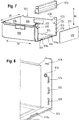
- Fig. 7 shows an exploded view of the refrigerated goods container 600.
- the refrigerated goods body 602 has a rear wall 604, a left side wall 606, a right side wall 608 and a bottom wall 614. From the bottom wall 614, a first retaining projection 616 protrudes. In this embodiment, the first retaining projection 616 is disposed on the front edge 615 of the bottom wall 614. Furthermore, two second retaining projections 618a, 618b project from the bottom wall 614 in this embodiment. The second retaining projections 618a, 618b and the first retaining projection 616 are spaced apart so that the front wall 610 can be inserted between these retaining projections.
- the refrigerated goods body 602 further includes support ribs, the support ribs 620, 622, 624 of the right side wall 608. Support ribs are also provided on the left side wall 606 (not shown). The support ribs of a side wall are spaced from each other.
- a bottom end portion is disposed between the holding protrusions 618a, 618b and 616.
- the front wall 610 is supported by the support ribs 620, 622, 624 and the holding projections 618a, 618b, 616 in a use position. In the embodiment of Fig. 6 .
- the use position is a position of the front wall 610 perpendicular to the bottom wall 614.
- a fastening projection 626 is provided as a corresponding fastening structure.
- the fastening projection 626 is formed as an annular projection.
- a Attachment hooks 628 provided as (further) corresponding attachment structure.
- Analogous mounting structures may be disposed on the left side wall 606 (not shown).
- the fastening hooks of the two side walls 606, 608 are preferably arranged in the height direction HR above the fastening projections of the two side walls 606, 608.
- the front wall 610 is fixed by the handle member 1200 in the use position, ie a removal of the front wall 610 with mounted handle member 1200 is not possible.
- Fig. 8 shows a section of theharigut actuallyerkorpuses 602.
- Fig. 9 shows the situation when the front wall 610 is brought to the refrigerated goods body 602 in a use position. This is done in the present embodiment by inserting the front wall 610 in a space between the support ribs 620, 622, 624 and the retaining projection 616. The insertion takes place in a direction of use or insertion ER.
- Fig. 10 shows a section of thedegut actuallyerkorpuses 602 with the front wall 610, which is held by the support ribs 620, 622, 624 and the retaining projection 616.
- Fig. 11 shows the refrigerated goods body 602 with front wall 610 in the situation when the handle member 1200 is mounted.
- the grip element 1200 is fastened in a height direction HR of the container substantially above the front wall 610 on the side walls 606, 608.
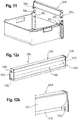
- Fig. 12a, 12b show the handle element 1200 from different perspectives.
- the grip element 1200 has a recessed grip 1202, a grip region 1201, attachment recesses as 1204, 1206, and attachment hook receptacles 1208, 1210 (1206, 1210 are not shown).
- the mounting recesses 1204, 1206 engage with the mounting projections 626, 630 on the side walls 606, 608 when mounting the handle member 1200 to the refrigerated goods body 602.
- the mounting hooks 628 and 632 (not shown) of the side walls 606, 608 latch with mounting hook receptacles 1208, 1210 of FIG Handle member 1200.
- the mounting hook receptacles 1208, 1210 and the mounting recesses 1204, 1206 are disposed on the side walls 1212, 1214 of the handle member 1200.
- the mounting hook receptacles 1208, 1210 are arranged in the height direction HR at a distance above the fastening recesses 1204, 1206 in the region of the recessed grip 1202.
- the recessed grip 1202 includes a curved portion 1216.
- the attachment hooks 628, 632 each have a hook portion 629, 631.
- a hook portion 629, 631 points upwards in a height direction HR.
- the fastening hooks 628, 632 have a width B and a thickness D, wherein the width B is greater than the thickness D.
- the width B is to be measured in the depth direction TR and the thickness D in the height direction HR of the refrigerated goods container 600.
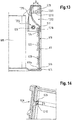
- the handle member 1200 has a lower end portion 1218 which forms an abutment area. When mounted / inserted front wall 610 is in this embodiment, the lower end portion or contact area 1218 on the outer side AS of the front wall 610 at. This is in Fig. 13 which shows a sectional view of a section of a refrigerated goods container 600 according to FIG Fig. 6 shows.
- Fig. 14 shows a sectional view of a section of the refrigerated goods 600, in which the locking of the fastening hook 628 is shown with the mounting hook receptacle 1212 from different perspectives.
- Fig. 14 shows how the mounting hook 628 engages the mounting hook receptacle 2016.
- the fastening projection 626 engages in the fastening recess 1210.
- Fig. 15 shows an alternative embodiment of a mounting hook in the refrigerated goods 600. Shown here is a mounting hook 634 on the side wall 608. This is a handle element 1500 is mounted, which corresponds to the handle hook member 1200 except for the mounting hooks.
- the attachment hook 634 has a width B and a thickness D, wherein the width B is greater than the thickness D. The width B is to be measured in the height direction HR and the thickness D in the depth direction TR of the refrigerated goods container 600. The same applies to a fastening hook on the side wall 606 (not shown).
- Fig. 16 shows the refrigerated goods body 602 with front wall 610 in the situation when the handle member 1500 is mounted.
- the front wall 610 in the use position on thedegut aserkorpus 602 of the handle member 1500 is attached in a vertical direction and then the handle member 1500 is pivoted to the latching of the handle member 1500 on the side walls 606, 608 in a pivoting direction VR.
- the refrigerated goods containers 300 and 116 may correspond to the refrigerated goods container 200 and / or the refrigerated goods container 600.
Landscapes
- Engineering & Computer Science (AREA)
- Chemical & Material Sciences (AREA)
- Combustion & Propulsion (AREA)
- Physics & Mathematics (AREA)
- Mechanical Engineering (AREA)
- Thermal Sciences (AREA)
- General Engineering & Computer Science (AREA)
- Devices That Are Associated With Refrigeration Equipment (AREA)
- Packages (AREA)
- Details Of Rigid Or Semi-Rigid Containers (AREA)
Claims (15)
- Contenant pour produits réfrigérés (200 ; 600) pour un appareil frigorifique avec une paroi inférieure (214 ; 614), deux parois latérales (206, 606 ; 208, 608), une paroi arrière (204 ; 604), qui constituent un corps de contenant pour produits réfrigérés (202 ; 602), et une paroi avant distincte (210 ; 610), constituée par un élément plan en forme de plaque, dans lequel la paroi avant (210 ; 610) présente un côté intérieur et un côté extérieur (AS), qui constituent des surfaces principales opposées l'une à l'autre, caractérisé en ce que le corps de contenant pour produits réfrigérés (202 ; 602) présente plusieurs nervures d'appui (220, 222, 224 ; 620, 622, 624) et au moins une première saillie de retenue (216 ; 616), qui maintiennent la paroi avant (210 ; 610) sur le corps de contenant pour produits réfrigérés (202 ; 602) dans une position d'utilisation, et en ce que les nervures d'appui (220, 222, 224 ; 620, 622, 624) et l'au moins une première saillie de retenue (216, 616) sont contiguës à différentes surfaces principales.
- Contenant pour produits réfrigérés (200 ; 600) selon la revendication 1, dans lequel le contenant pour produits réfrigérés (200 ; 600) présente un élément de préhension (400 ; 600), et l'élément de préhension (400, 600) arrête la paroi avant (210 ; 610) de sorte que la paroi avant (210 ; 610) soit fixée dans la position d'utilisation.
- Contenant pour produits réfrigérés (200 ; 600) selon la revendication 2, dans lequel l'élément de préhension (400 ; 1200 ; 1500) présente un élément de limitation (416, 1216), disposé dans un sens de la hauteur (HR) du contenant pour produits réfrigérés (200, 600) sur un bord supérieur (211 ; 611) de la paroi avant (210 ; 610).
- Contenant pour produits réfrigérés (200 ; 600) selon l'une des revendications 2 ou 3, dans lequel l'élément de préhension (400 ; 1200) présente une poignée concave (402 ; 1202), au moins essentiellement disposée dans le sens de la hauteur (HR) du contenant pour produits réfrigérés (200, 600) sur le bord supérieur (211 ; 611) de la paroi avant (210 ; 610).
- Contenant pour produits réfrigérés (200 ; 600) selon la revendication 4, dans lequel la poignée concave (402 ; 1202) est définie par une section galbée (416 ; 1216) de l'élément de préhension (400 ; 1200) et une section partielle de la section galbée (416 ; 1216) constitue l'élément de limitation (416, 1216).
- Contenant pour produits réfrigérés (200, 600) selon l'une des revendications 2 à 5, dans lequel l'élément de préhension présente une zone d'appui (418, 1218) contiguë à une zone de contact de la paroi avant (410, 610) éloignée du fond sur une des surfaces principales.
- Contenant pour produits réfrigérés (200, 600) selon l'une des revendications 2 à 6, dans lequel l'élément de préhension (400 ; 1200 ; 1500) présente des structures de fixation (404, 406, 408, 410 ; 1204, 1206, 1208, 1210), et les structures de fixation servent à la fixation de l'élément de préhension (400 ; 1200 ; 1500) aux parois latérales (206, 208 ; 606, 608), et dans lequel des structures de fixation correspondantes (226 ; 228, 230, 232 ; 626, 628, 630, 632) sont prévues sur les parois latérales.
- Contenant pour produits réfrigérés (200 ; 600) selon la revendication 7, dans lequel l'élément de préhension (400 ; 1200 ; 1500) présente en guise de structures de fixation des évidements de fixation (404, 406 ; 1204, 1206), et un évidement de fixation (404, 406 ; 1204, 1206) s'engrène avec une saillie de fixation (226 ; 626) comme structure de fixation correspondante d'une paroi latérale (206, 208 ; 606, 608) ; et/ou l'élément de préhension présente en guise de structures de fixation des saillies de fixation, et une saillie de fixation s'engrène avec un évidement de fixation comme structure de fixation correspondante d'une paroi latérale.
- Contenant pour produits réfrigérés (200 ; 600) selon la revendication 7 ou 8, dans lequel l'élément de préhension présente en guise de structures de fixation des crochets de fixation, et un crochet de fixation s'engrène avec un logement de fixation comme structure de fixation correspondante d'une paroi latérale ; et/ou l'élément de préhension (400 ; 1200 ; 1500) présente en guise de structures de fixation des logements de crochets de fixation (408 ; 410 ; 1208 ; 1210) et un logement de crochet de fixation (408 ; 410 ; 1208 ; 1210) s'engrène avec un crochet de fixation (228, 230 ; 628, 630) comme structure de fixation correspondante d'une paroi latérale (206, 208 ; 606, 608).
- Contenant pour produits réfrigérés (200 ; 600) selon l'une des revendications 1 à 9, dans lequel l'au moins une première saillie de retenue (216, 616) est disposée sur la paroi inférieure (214, 614) du contenant pour produits réfrigérés (200 ; 600).
- Contenant pour produits réfrigérés (200 ; 600) selon l'une des revendications 1 à 10, dans lequel l'au moins une première saillie de retenue (216, 616) est disposée sur un bord avant (215 ; 615) de la paroi inférieure (214, 614) et en particulier aménagée sous forme de moulure.
- Contenant pour produits réfrigérés (200 ; 600) selon l'une des revendications 1 à 11, dans lequel le contenant pour produits réfrigérés présente au moins une deuxième saillie de retenue (218a, 218b ; 618a, 618b), faisant saillie de la paroi inférieure, et l'au moins une première saillie de retenue est contiguë au côté extérieur (AS) de la paroi avant (210 ; 610) et l'au moins une deuxième saillie de retenue (218a, 218b ; 618a, 618b) est contiguë au côté intérieur de la paroi avant (210 ; 610).
- Contenant pour produits réfrigérés (200 ; 600) selon l'une des revendications 1 à 12, dans lequel au moins une première saillie de retenue fait saillie de l'une des parois latérales à proximité de la paroi de fond (214, 614).
- Appareil frigorifique ménager (100), comprenant un contenant interne pour produits réfrigérés (106), qui constitue un espace intérieur pour l'accueil de produits réfrigérés, et un contenant pour produits réfrigérés (200 ; 600) selon une ou plusieurs des revendications 1 à 13, dans lequel le contenant pour produits réfrigérés (200 ; 600) est logé dans l'espace intérieur.
- Procédé de montage d'une paroi avant (210, 610) sur un corps de contenant pour produits réfrigérés (202 ; 602) selon une ou plusieurs des revendications 2 à 13, comprenant les étapes de :- mise à disposition du corps de contenant pour produits réfrigérés (202, 602) et d'une paroi avant séparée (210, 610) ;- disposition de la paroi avant (210, 610) sur le corps de contenant pour produits réfrigérés (202 ; 602) dans la position d'utilisation ;- fixation de l'élément de préhension (1500) sur le corps de contenant pour produits réfrigérés pour la fixation de la paroi avant (210, 610) dans la position d'utilisation par insertion de l'élément de préhension (1500) dans un sens d'utilisation et pivotement subséquent de l'élément de préhension (1500) jusqu'à l'encliquètement de l'élément de préhension (1500) sur les parois latérales.
Priority Applications (1)
| Application Number | Priority Date | Filing Date | Title |
|---|---|---|---|
| PL17161403T PL3244149T3 (pl) | 2016-05-12 | 2017-03-16 | Pojemnik na produkty do chłodzenia z oddzielnym frontem |
Applications Claiming Priority (1)
| Application Number | Priority Date | Filing Date | Title |
|---|---|---|---|
| DE102016208207.8A DE102016208207A1 (de) | 2016-05-12 | 2016-05-12 | Kühlgutbehälter mit separater Front |
Publications (2)
| Publication Number | Publication Date |
|---|---|
| EP3244149A1 EP3244149A1 (fr) | 2017-11-15 |
| EP3244149B1 true EP3244149B1 (fr) | 2019-10-23 |
Family
ID=58347300
Family Applications (1)
| Application Number | Title | Priority Date | Filing Date |
|---|---|---|---|
| EP17161403.5A Active EP3244149B1 (fr) | 2016-05-12 | 2017-03-16 | Récipient pour produits réfrigérés ayant une partie avant séparée |
Country Status (4)
| Country | Link |
|---|---|
| EP (1) | EP3244149B1 (fr) |
| CN (1) | CN107367104B (fr) |
| DE (1) | DE102016208207A1 (fr) |
| PL (1) | PL3244149T3 (fr) |
Citations (1)
| Publication number | Priority date | Publication date | Assignee | Title |
|---|---|---|---|---|
| KR20050057995A (ko) * | 2003-12-11 | 2005-06-16 | 엘지전자 주식회사 | 서랍을 구비한 냉장고 |
Family Cites Families (24)
| Publication number | Priority date | Publication date | Assignee | Title |
|---|---|---|---|---|
| DE4304484A1 (de) * | 1993-02-15 | 1994-08-18 | Bosch Siemens Hausgeraete | Behälter, insbesondere schubladenartiger Behälter |
| US5437503A (en) * | 1993-06-01 | 1995-08-01 | General Electric Company | Modular storage drawer assembly for use in a refrigerator |
| JP3419988B2 (ja) * | 1996-04-16 | 2003-06-23 | 松下冷機株式会社 | 冷蔵庫 |
| JPH109760A (ja) * | 1996-06-24 | 1998-01-16 | Yamato Ind Kk | 収容庫用のドア及びドアライナー |
| US5921648A (en) * | 1997-12-31 | 1999-07-13 | Rong; Liu Ching | Drawer assembly for a storage bin |
| DE29809636U1 (de) | 1998-05-28 | 1999-05-27 | BSH Bosch und Siemens Hausgeräte GmbH, 81669 München | Ablagefach für eine Kühlschranktür |
| JP3615455B2 (ja) * | 2000-03-30 | 2005-02-02 | 三洋電機株式会社 | 冷蔵庫等の食品貯蔵装置 |
| JP4499379B2 (ja) * | 2003-06-17 | 2010-07-07 | エルジー エレクトロニクス インコーポレイティド | 冷蔵庫用野菜ボックス |
| CN2665636Y (zh) * | 2003-09-19 | 2004-12-22 | 合肥美菱股份有限公司 | 前挡板可拆卸的冰箱抽屉 |
| DE102005021588A1 (de) * | 2005-05-10 | 2006-11-16 | BSH Bosch und Siemens Hausgeräte GmbH | Kühlgutbehälter |
| DE202005012342U1 (de) * | 2005-08-05 | 2005-10-20 | BSH Bosch und Siemens Hausgeräte GmbH | Modular Kühlgutbehälter |
| CN101135533B (zh) * | 2006-08-28 | 2011-08-31 | 海尔集团公司 | 带旋转式前盖的果菜盒 |
| ITTO20070928A1 (it) * | 2007-12-20 | 2009-06-21 | Indesit Co Spa | Cassetto per un apparato di refrigerazione e relativo apparato di refrigerazione |
| CN201322503Y (zh) * | 2008-12-23 | 2009-10-07 | 海信科龙电器股份有限公司 | 一种冰箱抽屉 |
| DE102010030989A1 (de) * | 2010-07-06 | 2012-01-12 | BSH Bosch und Siemens Hausgeräte GmbH | Kühlgutbehälter für ein Kältegerät |
| CN101963025A (zh) * | 2010-08-17 | 2011-02-02 | 钟秋怡 | 银行票据立式保管箱 |
| DE102011017735A1 (de) * | 2011-04-28 | 2012-10-31 | BSH Bosch und Siemens Hausgeräte GmbH | Kühlgutbehälter und Kältegerät mit einem Kühlgutbehälter |
| CN202346032U (zh) * | 2011-11-25 | 2012-07-25 | 王康 | 折叠纸箱 |
| CN102599840B (zh) * | 2012-04-20 | 2014-08-06 | 金红叶纸业集团有限公司 | 抽纸盒 |
| KR20130119272A (ko) * | 2012-04-23 | 2013-10-31 | 동부대우전자 주식회사 | 서랍식 도어가 구비된 냉장고 |
| CN204156394U (zh) * | 2014-11-01 | 2015-02-11 | 江苏华通电气科技有限公司 | 箱型固定式封闭环网开关设备 |
| DE102015206860A1 (de) * | 2015-04-16 | 2016-10-20 | BSH Hausgeräte GmbH | Haushaltskältegerät mit entnehmbarer Trennwand in einer Lebensmittelaufnahme-Schale |
| CN204678790U (zh) * | 2015-05-09 | 2015-09-30 | 苏州爱友电器有限公司 | 冰箱抽屉 |
| CN205119644U (zh) * | 2015-10-29 | 2016-03-30 | 青岛海尔股份有限公司 | 抽屉及冰箱 |
-
2016
- 2016-05-12 DE DE102016208207.8A patent/DE102016208207A1/de not_active Withdrawn
-
2017
- 2017-03-16 PL PL17161403T patent/PL3244149T3/pl unknown
- 2017-03-16 EP EP17161403.5A patent/EP3244149B1/fr active Active
- 2017-05-04 CN CN201710308043.XA patent/CN107367104B/zh active Active
Patent Citations (1)
| Publication number | Priority date | Publication date | Assignee | Title |
|---|---|---|---|---|
| KR20050057995A (ko) * | 2003-12-11 | 2005-06-16 | 엘지전자 주식회사 | 서랍을 구비한 냉장고 |
Also Published As
| Publication number | Publication date |
|---|---|
| PL3244149T3 (pl) | 2020-05-18 |
| EP3244149A1 (fr) | 2017-11-15 |
| CN107367104A (zh) | 2017-11-21 |
| CN107367104B (zh) | 2021-02-19 |
| DE102016208207A1 (de) | 2017-11-16 |
Similar Documents
| Publication | Publication Date | Title |
|---|---|---|
| EP2126493B1 (fr) | Appareil frigorifique | |
| EP2414756B1 (fr) | Appareil frigorifique ménager | |
| DE102007005951A1 (de) | Butterfach für ein Kältegerät | |
| EP2606301B1 (fr) | Appareil de froid pourvu d'une clayette pour denrées alimentaires à refroidir | |
| EP3283260B1 (fr) | Boîte d'assortiment et ensemble comportant au moins une boîte d'assortiment et une bande de retenue | |
| EP1379820B1 (fr) | Recipient de stockage pour appareils frigorifiques | |
| DE102009046614A1 (de) | Kältegerät mit einem Türabsteller und einer optisch herausgestellten Rastvorrichtung | |
| EP2606298B1 (fr) | Un appareil frigorifique avec une étagère | |
| EP2220446A1 (fr) | Appareil réfrigérant | |
| EP2913610A1 (fr) | Réfrigérateur domestique avec tablette et doté d'un dispositif de fixation monté sur la tablette | |
| DE102010041950A1 (de) | Kältegerät mit einem Fachboden | |
| EP1728036A1 (fr) | Support de bouteille pour appareil frigorifique | |
| EP4067791B1 (fr) | Gros appareil électroménager sous forme de réfrigérateur | |
| EP3163233B1 (fr) | Appareil frigorifique ménager | |
| EP3244149B1 (fr) | Récipient pour produits réfrigérés ayant une partie avant séparée | |
| EP0043540A2 (fr) | Coffret à tiroirs cloisonnés pour assortiment | |
| EP2420783B1 (fr) | Appareil frigorifique doté de moyens d'arrêt pour un sol technique | |
| EP0582780B1 (fr) | Meuble comprenant des éléments porteurs pour étagères à introduire dans l'espace intérieur du meuble | |
| EP0611931A1 (fr) | Conteneur, en particulier en forme de tiroir | |
| DE102009028787A1 (de) | Haushaltskältegerät mit einer Abstellplatte und Haltern für Behälter, insbesondere Gastronorm-Behälter | |
| DE3924138A1 (de) | Lunch-box | |
| EP3537077B1 (fr) | Compartiment de stockage pour produits à réfrigérer pourvu d'un cadre en l, porte ainsi qu'appareil de refroidissement électroménager | |
| EP1377782B1 (fr) | Bac a gla ons | |
| EP2980513A1 (fr) | Support de produit refrigere pour un appareil frigorifique | |
| EP3546859B1 (fr) | Appareil frigorifique ménager doté d'une étagère en forme de plaque fixée |
Legal Events
| Date | Code | Title | Description |
|---|---|---|---|
| PUAI | Public reference made under article 153(3) epc to a published international application that has entered the european phase |
Free format text: ORIGINAL CODE: 0009012 |
|
| STAA | Information on the status of an ep patent application or granted ep patent |
Free format text: STATUS: THE APPLICATION HAS BEEN PUBLISHED |
|
| AK | Designated contracting states |
Kind code of ref document: A1 Designated state(s): AL AT BE BG CH CY CZ DE DK EE ES FI FR GB GR HR HU IE IS IT LI LT LU LV MC MK MT NL NO PL PT RO RS SE SI SK SM TR |
|
| AX | Request for extension of the european patent |
Extension state: BA ME |
|
| STAA | Information on the status of an ep patent application or granted ep patent |
Free format text: STATUS: REQUEST FOR EXAMINATION WAS MADE |
|
| 17P | Request for examination filed |
Effective date: 20180515 |
|
| RBV | Designated contracting states (corrected) |
Designated state(s): AL AT BE BG CH CY CZ DE DK EE ES FI FR GB GR HR HU IE IS IT LI LT LU LV MC MK MT NL NO PL PT RO RS SE SI SK SM TR |
|
| RIC1 | Information provided on ipc code assigned before grant |
Ipc: A47B 88/95 20170101ALN20190425BHEP Ipc: A47B 88/90 20170101ALI20190425BHEP Ipc: F25D 25/02 20060101AFI20190425BHEP |
|
| GRAP | Despatch of communication of intention to grant a patent |
Free format text: ORIGINAL CODE: EPIDOSNIGR1 |
|
| STAA | Information on the status of an ep patent application or granted ep patent |
Free format text: STATUS: GRANT OF PATENT IS INTENDED |
|
| INTG | Intention to grant announced |
Effective date: 20190603 |
|
| GRAS | Grant fee paid |
Free format text: ORIGINAL CODE: EPIDOSNIGR3 |
|
| GRAA | (expected) grant |
Free format text: ORIGINAL CODE: 0009210 |
|
| STAA | Information on the status of an ep patent application or granted ep patent |
Free format text: STATUS: THE PATENT HAS BEEN GRANTED |
|
| AK | Designated contracting states |
Kind code of ref document: B1 Designated state(s): AL AT BE BG CH CY CZ DE DK EE ES FI FR GB GR HR HU IE IS IT LI LT LU LV MC MK MT NL NO PL PT RO RS SE SI SK SM TR |
|
| REG | Reference to a national code |
Ref country code: GB Ref legal event code: FG4D Free format text: NOT ENGLISH |
|
| REG | Reference to a national code |
Ref country code: CH Ref legal event code: EP |
|
| REG | Reference to a national code |
Ref country code: IE Ref legal event code: FG4D Free format text: LANGUAGE OF EP DOCUMENT: GERMAN |
|
| REG | Reference to a national code |
Ref country code: DE Ref legal event code: R096 Ref document number: 502017002617 Country of ref document: DE |
|
| REG | Reference to a national code |
Ref country code: AT Ref legal event code: REF Ref document number: 1194102 Country of ref document: AT Kind code of ref document: T Effective date: 20191115 |
|
| REG | Reference to a national code |
Ref country code: NL Ref legal event code: MP Effective date: 20191023 |
|
| REG | Reference to a national code |
Ref country code: LT Ref legal event code: MG4D |
|
| PG25 | Lapsed in a contracting state [announced via postgrant information from national office to epo] |
Ref country code: NL Free format text: LAPSE BECAUSE OF FAILURE TO SUBMIT A TRANSLATION OF THE DESCRIPTION OR TO PAY THE FEE WITHIN THE PRESCRIBED TIME-LIMIT Effective date: 20191023 Ref country code: LT Free format text: LAPSE BECAUSE OF FAILURE TO SUBMIT A TRANSLATION OF THE DESCRIPTION OR TO PAY THE FEE WITHIN THE PRESCRIBED TIME-LIMIT Effective date: 20191023 Ref country code: NO Free format text: LAPSE BECAUSE OF FAILURE TO SUBMIT A TRANSLATION OF THE DESCRIPTION OR TO PAY THE FEE WITHIN THE PRESCRIBED TIME-LIMIT Effective date: 20200123 Ref country code: GR Free format text: LAPSE BECAUSE OF FAILURE TO SUBMIT A TRANSLATION OF THE DESCRIPTION OR TO PAY THE FEE WITHIN THE PRESCRIBED TIME-LIMIT Effective date: 20200124 Ref country code: PT Free format text: LAPSE BECAUSE OF FAILURE TO SUBMIT A TRANSLATION OF THE DESCRIPTION OR TO PAY THE FEE WITHIN THE PRESCRIBED TIME-LIMIT Effective date: 20200224 Ref country code: LV Free format text: LAPSE BECAUSE OF FAILURE TO SUBMIT A TRANSLATION OF THE DESCRIPTION OR TO PAY THE FEE WITHIN THE PRESCRIBED TIME-LIMIT Effective date: 20191023 Ref country code: SE Free format text: LAPSE BECAUSE OF FAILURE TO SUBMIT A TRANSLATION OF THE DESCRIPTION OR TO PAY THE FEE WITHIN THE PRESCRIBED TIME-LIMIT Effective date: 20191023 Ref country code: BG Free format text: LAPSE BECAUSE OF FAILURE TO SUBMIT A TRANSLATION OF THE DESCRIPTION OR TO PAY THE FEE WITHIN THE PRESCRIBED TIME-LIMIT Effective date: 20200123 Ref country code: FI Free format text: LAPSE BECAUSE OF FAILURE TO SUBMIT A TRANSLATION OF THE DESCRIPTION OR TO PAY THE FEE WITHIN THE PRESCRIBED TIME-LIMIT Effective date: 20191023 |
|
| PG25 | Lapsed in a contracting state [announced via postgrant information from national office to epo] |
Ref country code: RS Free format text: LAPSE BECAUSE OF FAILURE TO SUBMIT A TRANSLATION OF THE DESCRIPTION OR TO PAY THE FEE WITHIN THE PRESCRIBED TIME-LIMIT Effective date: 20191023 Ref country code: IS Free format text: LAPSE BECAUSE OF FAILURE TO SUBMIT A TRANSLATION OF THE DESCRIPTION OR TO PAY THE FEE WITHIN THE PRESCRIBED TIME-LIMIT Effective date: 20200224 Ref country code: HR Free format text: LAPSE BECAUSE OF FAILURE TO SUBMIT A TRANSLATION OF THE DESCRIPTION OR TO PAY THE FEE WITHIN THE PRESCRIBED TIME-LIMIT Effective date: 20191023 |
|
| PG25 | Lapsed in a contracting state [announced via postgrant information from national office to epo] |
Ref country code: AL Free format text: LAPSE BECAUSE OF FAILURE TO SUBMIT A TRANSLATION OF THE DESCRIPTION OR TO PAY THE FEE WITHIN THE PRESCRIBED TIME-LIMIT Effective date: 20191023 |
|
| REG | Reference to a national code |
Ref country code: DE Ref legal event code: R097 Ref document number: 502017002617 Country of ref document: DE |
|
| PG2D | Information on lapse in contracting state deleted |
Ref country code: IS |
|
| PG25 | Lapsed in a contracting state [announced via postgrant information from national office to epo] |
Ref country code: EE Free format text: LAPSE BECAUSE OF FAILURE TO SUBMIT A TRANSLATION OF THE DESCRIPTION OR TO PAY THE FEE WITHIN THE PRESCRIBED TIME-LIMIT Effective date: 20191023 Ref country code: DK Free format text: LAPSE BECAUSE OF FAILURE TO SUBMIT A TRANSLATION OF THE DESCRIPTION OR TO PAY THE FEE WITHIN THE PRESCRIBED TIME-LIMIT Effective date: 20191023 Ref country code: ES Free format text: LAPSE BECAUSE OF FAILURE TO SUBMIT A TRANSLATION OF THE DESCRIPTION OR TO PAY THE FEE WITHIN THE PRESCRIBED TIME-LIMIT Effective date: 20191023 Ref country code: RO Free format text: LAPSE BECAUSE OF FAILURE TO SUBMIT A TRANSLATION OF THE DESCRIPTION OR TO PAY THE FEE WITHIN THE PRESCRIBED TIME-LIMIT Effective date: 20191023 Ref country code: CZ Free format text: LAPSE BECAUSE OF FAILURE TO SUBMIT A TRANSLATION OF THE DESCRIPTION OR TO PAY THE FEE WITHIN THE PRESCRIBED TIME-LIMIT Effective date: 20191023 Ref country code: IS Free format text: LAPSE BECAUSE OF FAILURE TO SUBMIT A TRANSLATION OF THE DESCRIPTION OR TO PAY THE FEE WITHIN THE PRESCRIBED TIME-LIMIT Effective date: 20200223 |
|
| PLBE | No opposition filed within time limit |
Free format text: ORIGINAL CODE: 0009261 |
|
| STAA | Information on the status of an ep patent application or granted ep patent |
Free format text: STATUS: NO OPPOSITION FILED WITHIN TIME LIMIT |
|
| PG25 | Lapsed in a contracting state [announced via postgrant information from national office to epo] |
Ref country code: SM Free format text: LAPSE BECAUSE OF FAILURE TO SUBMIT A TRANSLATION OF THE DESCRIPTION OR TO PAY THE FEE WITHIN THE PRESCRIBED TIME-LIMIT Effective date: 20191023 Ref country code: SK Free format text: LAPSE BECAUSE OF FAILURE TO SUBMIT A TRANSLATION OF THE DESCRIPTION OR TO PAY THE FEE WITHIN THE PRESCRIBED TIME-LIMIT Effective date: 20191023 |
|
| 26N | No opposition filed |
Effective date: 20200724 |
|
| PG25 | Lapsed in a contracting state [announced via postgrant information from national office to epo] |
Ref country code: MC Free format text: LAPSE BECAUSE OF FAILURE TO SUBMIT A TRANSLATION OF THE DESCRIPTION OR TO PAY THE FEE WITHIN THE PRESCRIBED TIME-LIMIT Effective date: 20191023 |
|
| REG | Reference to a national code |
Ref country code: CH Ref legal event code: PL |
|
| PG25 | Lapsed in a contracting state [announced via postgrant information from national office to epo] |
Ref country code: SI Free format text: LAPSE BECAUSE OF FAILURE TO SUBMIT A TRANSLATION OF THE DESCRIPTION OR TO PAY THE FEE WITHIN THE PRESCRIBED TIME-LIMIT Effective date: 20191023 |
|
| REG | Reference to a national code |
Ref country code: BE Ref legal event code: MM Effective date: 20200331 |
|
| PG25 | Lapsed in a contracting state [announced via postgrant information from national office to epo] |
Ref country code: LU Free format text: LAPSE BECAUSE OF NON-PAYMENT OF DUE FEES Effective date: 20200316 |
|
| PG25 | Lapsed in a contracting state [announced via postgrant information from national office to epo] |
Ref country code: FR Free format text: LAPSE BECAUSE OF NON-PAYMENT OF DUE FEES Effective date: 20200331 Ref country code: IE Free format text: LAPSE BECAUSE OF NON-PAYMENT OF DUE FEES Effective date: 20200316 Ref country code: LI Free format text: LAPSE BECAUSE OF NON-PAYMENT OF DUE FEES Effective date: 20200331 Ref country code: CH Free format text: LAPSE BECAUSE OF NON-PAYMENT OF DUE FEES Effective date: 20200331 |
|
| PG25 | Lapsed in a contracting state [announced via postgrant information from national office to epo] |
Ref country code: BE Free format text: LAPSE BECAUSE OF NON-PAYMENT OF DUE FEES Effective date: 20200331 |
|
| GBPC | Gb: european patent ceased through non-payment of renewal fee |
Effective date: 20210316 |
|
| PG25 | Lapsed in a contracting state [announced via postgrant information from national office to epo] |
Ref country code: GB Free format text: LAPSE BECAUSE OF NON-PAYMENT OF DUE FEES Effective date: 20210316 |
|
| PG25 | Lapsed in a contracting state [announced via postgrant information from national office to epo] |
Ref country code: MT Free format text: LAPSE BECAUSE OF FAILURE TO SUBMIT A TRANSLATION OF THE DESCRIPTION OR TO PAY THE FEE WITHIN THE PRESCRIBED TIME-LIMIT Effective date: 20191023 Ref country code: CY Free format text: LAPSE BECAUSE OF FAILURE TO SUBMIT A TRANSLATION OF THE DESCRIPTION OR TO PAY THE FEE WITHIN THE PRESCRIBED TIME-LIMIT Effective date: 20191023 |
|
| PG25 | Lapsed in a contracting state [announced via postgrant information from national office to epo] |
Ref country code: MK Free format text: LAPSE BECAUSE OF FAILURE TO SUBMIT A TRANSLATION OF THE DESCRIPTION OR TO PAY THE FEE WITHIN THE PRESCRIBED TIME-LIMIT Effective date: 20191023 |
|
| REG | Reference to a national code |
Ref country code: AT Ref legal event code: MM01 Ref document number: 1194102 Country of ref document: AT Kind code of ref document: T Effective date: 20220316 |
|
| PG25 | Lapsed in a contracting state [announced via postgrant information from national office to epo] |
Ref country code: AT Free format text: LAPSE BECAUSE OF NON-PAYMENT OF DUE FEES Effective date: 20220316 |
|
| PGFP | Annual fee paid to national office [announced via postgrant information from national office to epo] |
Ref country code: IT Payment date: 20230331 Year of fee payment: 7 |
|
| PGFP | Annual fee paid to national office [announced via postgrant information from national office to epo] |
Ref country code: DE Payment date: 20250331 Year of fee payment: 9 |
|
| PGFP | Annual fee paid to national office [announced via postgrant information from national office to epo] |
Ref country code: PL Payment date: 20250306 Year of fee payment: 9 |
|
| PG25 | Lapsed in a contracting state [announced via postgrant information from national office to epo] |
Ref country code: IT Free format text: LAPSE BECAUSE OF NON-PAYMENT OF DUE FEES Effective date: 20240316 |
|
| PGFP | Annual fee paid to national office [announced via postgrant information from national office to epo] |
Ref country code: TR Payment date: 20250307 Year of fee payment: 9 |