EP3244867B1 - Anti-aging applicator - Google Patents
Anti-aging applicator Download PDFInfo
- Publication number
- EP3244867B1 EP3244867B1 EP15831199.3A EP15831199A EP3244867B1 EP 3244867 B1 EP3244867 B1 EP 3244867B1 EP 15831199 A EP15831199 A EP 15831199A EP 3244867 B1 EP3244867 B1 EP 3244867B1
- Authority
- EP
- European Patent Office
- Prior art keywords
- end effector
- skin
- motor
- contact points
- appliance
- Prior art date
- Legal status (The legal status is an assumption and is not a legal conclusion. Google has not performed a legal analysis and makes no representation as to the accuracy of the status listed.)
- Active
Links
Images


Classifications
-
- A—HUMAN NECESSITIES
- A61—MEDICAL OR VETERINARY SCIENCE; HYGIENE
- A61H—PHYSICAL THERAPY APPARATUS, e.g. DEVICES FOR LOCATING OR STIMULATING REFLEX POINTS IN THE BODY; ARTIFICIAL RESPIRATION; MASSAGE; BATHING DEVICES FOR SPECIAL THERAPEUTIC OR HYGIENIC PURPOSES OR SPECIFIC PARTS OF THE BODY
- A61H7/00—Devices for suction-kneading massage; Devices for massaging the skin by rubbing or brushing not otherwise provided for
- A61H7/002—Devices for suction-kneading massage; Devices for massaging the skin by rubbing or brushing not otherwise provided for by rubbing or brushing
- A61H7/004—Devices for suction-kneading massage; Devices for massaging the skin by rubbing or brushing not otherwise provided for by rubbing or brushing power-driven, e.g. electrical
- A61H7/005—Devices for suction-kneading massage; Devices for massaging the skin by rubbing or brushing not otherwise provided for by rubbing or brushing power-driven, e.g. electrical hand-held
-
- A—HUMAN NECESSITIES
- A61—MEDICAL OR VETERINARY SCIENCE; HYGIENE
- A61H—PHYSICAL THERAPY APPARATUS, e.g. DEVICES FOR LOCATING OR STIMULATING REFLEX POINTS IN THE BODY; ARTIFICIAL RESPIRATION; MASSAGE; BATHING DEVICES FOR SPECIAL THERAPEUTIC OR HYGIENIC PURPOSES OR SPECIFIC PARTS OF THE BODY
- A61H1/00—Apparatus for passive exercising; Vibrating apparatus; Chiropractic devices, e.g. body impacting devices, external devices for briefly extending or aligning unbroken bones
-
- A—HUMAN NECESSITIES
- A61—MEDICAL OR VETERINARY SCIENCE; HYGIENE
- A61H—PHYSICAL THERAPY APPARATUS, e.g. DEVICES FOR LOCATING OR STIMULATING REFLEX POINTS IN THE BODY; ARTIFICIAL RESPIRATION; MASSAGE; BATHING DEVICES FOR SPECIAL THERAPEUTIC OR HYGIENIC PURPOSES OR SPECIFIC PARTS OF THE BODY
- A61H23/00—Percussion or vibration massage, e.g. using supersonic vibration; Suction-vibration massage; Massage with moving diaphragms
- A61H23/02—Percussion or vibration massage, e.g. using supersonic vibration; Suction-vibration massage; Massage with moving diaphragms with electric or magnetic drive
-
- A—HUMAN NECESSITIES
- A61—MEDICAL OR VETERINARY SCIENCE; HYGIENE
- A61H—PHYSICAL THERAPY APPARATUS, e.g. DEVICES FOR LOCATING OR STIMULATING REFLEX POINTS IN THE BODY; ARTIFICIAL RESPIRATION; MASSAGE; BATHING DEVICES FOR SPECIAL THERAPEUTIC OR HYGIENIC PURPOSES OR SPECIFIC PARTS OF THE BODY
- A61H2201/00—Characteristics of apparatus not provided for in the preceding codes
- A61H2201/01—Constructive details
- A61H2201/0119—Support for the device
- A61H2201/0153—Support for the device hand-held
-
- A—HUMAN NECESSITIES
- A61—MEDICAL OR VETERINARY SCIENCE; HYGIENE
- A61H—PHYSICAL THERAPY APPARATUS, e.g. DEVICES FOR LOCATING OR STIMULATING REFLEX POINTS IN THE BODY; ARTIFICIAL RESPIRATION; MASSAGE; BATHING DEVICES FOR SPECIAL THERAPEUTIC OR HYGIENIC PURPOSES OR SPECIFIC PARTS OF THE BODY
- A61H2201/00—Characteristics of apparatus not provided for in the preceding codes
- A61H2201/01—Constructive details
- A61H2201/0165—Damping, vibration related features
-
- A—HUMAN NECESSITIES
- A61—MEDICAL OR VETERINARY SCIENCE; HYGIENE
- A61H—PHYSICAL THERAPY APPARATUS, e.g. DEVICES FOR LOCATING OR STIMULATING REFLEX POINTS IN THE BODY; ARTIFICIAL RESPIRATION; MASSAGE; BATHING DEVICES FOR SPECIAL THERAPEUTIC OR HYGIENIC PURPOSES OR SPECIFIC PARTS OF THE BODY
- A61H2201/00—Characteristics of apparatus not provided for in the preceding codes
- A61H2201/10—Characteristics of apparatus not provided for in the preceding codes with further special therapeutic means, e.g. electrotherapy, magneto therapy or radiation therapy, chromo therapy, infrared or ultraviolet therapy
- A61H2201/105—Characteristics of apparatus not provided for in the preceding codes with further special therapeutic means, e.g. electrotherapy, magneto therapy or radiation therapy, chromo therapy, infrared or ultraviolet therapy with means for delivering media, e.g. drugs or cosmetics
-
- A—HUMAN NECESSITIES
- A61—MEDICAL OR VETERINARY SCIENCE; HYGIENE
- A61H—PHYSICAL THERAPY APPARATUS, e.g. DEVICES FOR LOCATING OR STIMULATING REFLEX POINTS IN THE BODY; ARTIFICIAL RESPIRATION; MASSAGE; BATHING DEVICES FOR SPECIAL THERAPEUTIC OR HYGIENIC PURPOSES OR SPECIFIC PARTS OF THE BODY
- A61H2201/00—Characteristics of apparatus not provided for in the preceding codes
- A61H2201/12—Driving means
- A61H2201/1207—Driving means with electric or magnetic drive
- A61H2201/1215—Rotary drive
- A61H2201/1223—Frequency controlled AC motor
-
- A—HUMAN NECESSITIES
- A61—MEDICAL OR VETERINARY SCIENCE; HYGIENE
- A61H—PHYSICAL THERAPY APPARATUS, e.g. DEVICES FOR LOCATING OR STIMULATING REFLEX POINTS IN THE BODY; ARTIFICIAL RESPIRATION; MASSAGE; BATHING DEVICES FOR SPECIAL THERAPEUTIC OR HYGIENIC PURPOSES OR SPECIFIC PARTS OF THE BODY
- A61H2201/00—Characteristics of apparatus not provided for in the preceding codes
- A61H2201/16—Physical interface with patient
- A61H2201/1602—Physical interface with patient kind of interface, e.g. head rest, knee support or lumbar support
- A61H2201/1654—Layer between the skin and massage elements, e.g. fluid or ball
-
- A—HUMAN NECESSITIES
- A61—MEDICAL OR VETERINARY SCIENCE; HYGIENE
- A61H—PHYSICAL THERAPY APPARATUS, e.g. DEVICES FOR LOCATING OR STIMULATING REFLEX POINTS IN THE BODY; ARTIFICIAL RESPIRATION; MASSAGE; BATHING DEVICES FOR SPECIAL THERAPEUTIC OR HYGIENIC PURPOSES OR SPECIFIC PARTS OF THE BODY
- A61H2201/00—Characteristics of apparatus not provided for in the preceding codes
- A61H2201/16—Physical interface with patient
- A61H2201/1657—Movement of interface, i.e. force application means
- A61H2201/1664—Movement of interface, i.e. force application means linear
- A61H2201/1669—Movement of interface, i.e. force application means linear moving along the body in a reciprocating manner
-
- A—HUMAN NECESSITIES
- A61—MEDICAL OR VETERINARY SCIENCE; HYGIENE
- A61H—PHYSICAL THERAPY APPARATUS, e.g. DEVICES FOR LOCATING OR STIMULATING REFLEX POINTS IN THE BODY; ARTIFICIAL RESPIRATION; MASSAGE; BATHING DEVICES FOR SPECIAL THERAPEUTIC OR HYGIENIC PURPOSES OR SPECIFIC PARTS OF THE BODY
- A61H2201/00—Characteristics of apparatus not provided for in the preceding codes
- A61H2201/16—Physical interface with patient
- A61H2201/1657—Movement of interface, i.e. force application means
- A61H2201/1671—Movement of interface, i.e. force application means rotational
-
- A—HUMAN NECESSITIES
- A61—MEDICAL OR VETERINARY SCIENCE; HYGIENE
- A61H—PHYSICAL THERAPY APPARATUS, e.g. DEVICES FOR LOCATING OR STIMULATING REFLEX POINTS IN THE BODY; ARTIFICIAL RESPIRATION; MASSAGE; BATHING DEVICES FOR SPECIAL THERAPEUTIC OR HYGIENIC PURPOSES OR SPECIFIC PARTS OF THE BODY
- A61H2201/00—Characteristics of apparatus not provided for in the preceding codes
- A61H2201/16—Physical interface with patient
- A61H2201/1683—Surface of interface
- A61H2201/1685—Surface of interface interchangeable
Definitions
- US 2013/0138023 relates to a device for massaging or treating the muscles of the back and neck of a patient.
- Document US-A1-2008/0262397 discloses a system for stimulating a portion of skin at a stimulation frequency, the system comprising: an appliance having a motor; and an end effector operably coupled to the motor, the end effector including a plurality of contact points at which the end effector is configured to contact the portion of skin.
- a system for stimulating a portion of skin at a stimulation frequency includes an appliance having a motor and an end effector operably coupled to the motor.
- the end effector includes a plurality of contact points at which the end effector is configured to contact the portion of skin.
- the plurality of contact points are located at a target distance from each other that is based on an inverse of a target stimulation frequency.
- the motor is configured to move the end effector such that, when the motor is operating, the system has an oscillating frequency based on the target stimulation frequency.
- the end effector produces a cyclical stimulus within the portion of skin at about the target stimulation frequency.
- the end effector includes a cup-shaped end configured such that the plurality of contact points are the only portions of the end effector to contact the portion of skin when the force is applied from the end effector to the portion of skin.
- the motor is configured to impart one or more of oscillatory motion or vibrational motion
- the end effector is configured to impart cyclical mechanical strain to the skin.
- the end effector includes a base portion and an end portion.
- the base portion has a mass selected such that the system has an oscillating frequency at about the target stimulation frequency when the motor is operating.
- the end portion includes the plurality of contact points, and wherein the end portion is connected to the base portion via a central support such that the plurality of contact points are cantilevered away from the central support.
- the end effector is releasably couplable to the appliance, the end effector includes a drive assembly that engages a drive hub of the appliance when the end effector is releasably coupled to the appliance, and the motor is operatively coupled to the drive hub such that operation of the motor causes movement of the drive hub that is transferred to the drive assembly to move the end effector.
- an end effector for stimulating a portion of skin at a stimulation frequency includes a base portion that is couplable to a motor and an end portion having a plurality of contact points at which the end effector is configured to contact the portion of skin.
- the plurality of contact points are located at a target distance from each other that is based on an inverse of the stimulation frequency.
- the end effector is configured such that, when the base portion is coupled to the motor and the motor is operating, the end effector has an oscillating frequency based on the stimulation frequency.
- the end portion has the plurality of contact points and the plurality of contact points includes at least three contact points arranged equidistantly from each other. In another example, a distance between each set of two of the three contact points is a whole integer increment of the inverse of the stimulation frequency. In another example, the end portion has the plurality of contact points and each of the plurality of contact points is located on one of a plurality of pads and edges of each of the plurality of pads has a rounded shoulder. In another example, the end portion has the plurality of contact points and each of the plurality of pads has at least one of a rounded shoulder, at least one slit across a face of the pad, or surface texturing on a face.
- a surface of the end portion has a hardness in a range from about 10 Shore A to about 90 Shore A.
- a surface of the end portion includes a rigid material.
- the end effector includes a ball dispenser configured to dispense a treatment composition to the portion of skin in response to the ball dispenser coming into contact with the portion of skin.
- the stimulation frequency is in a range from about 65 Hz to about 120 Hz.
- the force applied from the end effector to the portion of skin is in a range from about 20 grams-force to about 500 grams-force.
- the method further includes applying a composition to the portion of skin using the end effector while driving the end effector at the oscillating frequency.
- applying the composition includes applying a composition configured to treat a condition of the portion of skin.
- driving the end effector at the oscillating frequency includes selecting the target stimulation frequency based on the condition of the portion of skin.
- mechanical stimuli e.g., applied cyclical strain, mechanical motion, applied strain, and the like
- biomarker e.g., protein
- a number of proteins within the skin can be regulated using, among other things, cyclical mechanical strain applied at particular frequencies using an end effector.
- the disclosed embodiments employ technologies and methodologies that stimulate frequency response of cells in the dermis and epidermis to induce production of proteins associated with young, healthy skin.
- Human skin cells (dermal fibroblasts in particular) respond to strain in tissue with cytoskeletal reordering and increased production in extracellular matrix proteins.
- the disclosed technologies and methodologies induce increased growth and repair activities from multiple cell types found in the skin, thereby producing an anti-aging effect.
- mechanical motion or strain generated in a range from about 65 Hz to about 120 Hz may stimulate anti-aging effects.
- the cumulative effects of applying cyclical mechanical strain as disclosed include one or more anti-aging effects.
- cutaneous cells will react to the stress by upregulating (increasing) production of certain proteins.
- the character and duration of the stress will affect which proteins are upregulated and to what extent.
- certain disclosed embodiments can be used to upregulate the production of integrin in the skin, which results in anti-aging effects by increasing epidermal cohesion.
- an end effector with a plurality of contact points is used for stimulating a portion of skin at a stimulation frequency where the contact points are located a target distance from each other that is based on an inverse of the stimulation frequency.
- a system for stimulating a portion of skin at a stimulation frequency includes an appliance and an end effector with a plurality of contact points that are located a distance from each other that is based on an inverse of the stimulation frequency.
- a method for stimulating a portion of skin at a stimulation frequency includes activating operation of a motor to impart movement to an end of an end effector and applying a force to bias the end effector toward the portion of skin to cause a cyclical stimulus of the portion of skin at about the stimulation frequency.
- cyclical stimuli include cyclical mechanical strain induced in the portion of skin, cyclical pressure waves induced into the portion of skin, and the like.
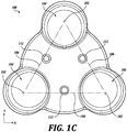
- FIGURES 1A to 1C An embodiment of an end effector 100 is depicted in FIGURES 1A to 1C .
- the end effector 100 includes contact points 102.
- contact points 102 can take a variety of shapes, configurations, and geometries including spheroidal, polygonal, cylindrical, conical, planar, parabolic, as well as regular or irregular forms.
- the end effector 100 includes a singular contact point that is located an offset distance away from the center of the end effector 100.
- the end effector 100 also includes contact areas 104. Each of the contact points 102 is located on one of the contact areas 104. In an embodiment, the contact points 102 are located a target distance 106 away from each other. For example, in an embodiment, the contact points 102 are located a target distance 106 away from each other determined from the inverse of the stimulation frequency. In the particular embodiment shown in FIGURES 1A to 1C , the contact points 102 include the contact points that are equidistant from each other (i.e., the distances 106 between contact points 102are all about the same, such as being within ⁇ 5% of each other).
- the end effector 100 includes a central portion 108 located between the contact areas 104.
- FIGURES 1A to 1C depict a coordinate system with X-, Y-, and Z-directions.
- the central portion 108 is depressed from the contact areas 104 such that the contact points 102 of the contact areas 104 are the points at which the contact areas 104 would contact a flat object lowered in the Z-direction.
- the end effector 100 includes a central support 110 on the opposite side of the central portion 108. As is seen in FIGURE 1B , the contact areas 104 are located on portions of end effector 100 that are cantilevered out from the central support 110. In some embodiments, the contact areas 104 have a surface quality configured to impart a cyclical mechanical strain to the skin (i.e., stainless steel, plastic, filaments, etc.) In one embodiment, the end effector 100 is made of a non-rigid material. Some examples of non-rigid materials include plastics (e.g., polyurethane, silicones), elastomeric materials (e.g., thermoplastic elastomers), rubber materials (e.g.
- the non-rigid material of the end effector 100 has a hardness in a range from about 10 Shore A to about 90 Shore A, as defined by the American Society for Testing and Materials (ASTM) standard D2240.
- ASTM American Society for Testing and Materials
- the end effector 100 is made of a rigid material (e.g., stainless steel, hard plastic, filaments, carbon fiber, etc.). In some embodiments, the end effector 100 is made from a combination of rigid and non-rigid materials. In one example, a structural portion of the end effector 100 (e.g. an interior of the end effector 100) is made of a rigid material and the portion of the end effector 100 that contacts the skin is made of a non-rigid material. In other embodiments, the end effector 100 is made from one or more of an anti-bacterial material or an anti-microbial material. The anti-bacterial material or the anti-microbial may be variations of any of the materials described herein (e.g., rigid materials, non-rigid materials).
- the end effector 100 includes fastener holes 112.
- mechanical fasteners e.g., screws, bolts, rivets, etc.
- the end effector 100 is molded onto an attachment base (e.g., using a second shot injection molding process).
- the end effector 100 is bonded (e.g., mechanically and/or chemically) with an adhesive onto an attachment base.
- the end effector 100 is couplable to a motor that is configured to move the end effector. In one example, when the end effector 100 is couplable to a motor and the motor is operating, the motor oscillates the end effector 100 with rotational movements about an axis in the Z-direction.
- the end effector 100 is used to stimulate a portion of skin at a stimulation frequency. In one embodiment, the end effector 100 is used to induce a cyclical response within a portion of skin at a target frequency. In one embodiment, the end effector 100 is used to apply a cyclical mechanical strain to a portion of skin responsive to an applied potential.
- the appliance 302 is configured to manage a duty cycle and frequency associated with driving an end effector. For example, in an embodiment, the appliance 302 includes circuitry configured to manage a duty cycle and frequency associated with driving an end effector.
- the stimulation frequency is selected based on a condition of the portion of skin.
- the stimulation frequency is selected based on an anti-aging effect that is activated by cyclical mechanical strain of the portion of skin at the stimulation frequency.
- the contact points 102 are located at a target distance from each other based on an inverse of the stimulation frequency.
- the inverse of the stimulation frequency i.e., the period
- the wavelength is 0.0333 meters per second, or 3.33 cm per second.
- Other examples of wavelength distances based on frequency are shown in TABLE 1.
- the contact points 102 are located at a distance from each other that is a whole integer increment of the inverse of the stimulation frequency.
- one whole integer increment of the inverse of the stimulation frequency is 3.08 cm.
- the distances 106 between the contact points 102 are 3.08 cm.
- the wavelength is 1.82 cm per second.
- One whole integer increment of the inverse of the stimulation frequency is 3.64 cm.
- the distances 106 between the contact points 102 are 3.64 cm.
- Many other examples of frequencies and whole integer increments of the inverse of the frequencies are possible.
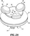
- FIGURES 2A and 2B Another embodiment of an end effector 200 is depicted in FIGURES 2A and 2B .
- the end effector 200 includes an end portion 202 and a base portion 204.
- the end portion 202 includes contact points 206 and contact areas 208. Each of the contact points 206 is located on one of the contact areas 208.
- the base portion 204 includes a drive assembly 210 that is configured to engage a drive hub of an appliance (not shown).
- the appliance includes a motor that is operatively coupled to the drive hub.
- the end portion 202 of the end effector 200 is connected to the base portion 204 of the end effector 200 via a central support 212.
- the contact areas 206 are located on portions of the end portion 202 that are cantilevered out from the central support 212.
- the end portion 202 is made of a non-rigid material and the contact areas 208 and the portions of the end portion 202 with the contact areas 208 have a spring-like quality that permits some movement of the contact areas 208.
- some or all of the base portion 204 is made of a rigid material.
- the portions of the end portion 202 with the contact areas 208 retain their spring-like quality even though some or all of the base portion 204 is made of a non-rigid material.
- the system of the end effector 200 and the motor has a resonance frequency.
- the resonance frequency of the system is a function of characteristics of the system, such as operational parameters of the motor, mass of the motor, and mass of the end effector 200.
- the end effector 200 is designed to be driven by a specific motor to stimulate a portion of skin at a stimulation frequency.
- the mass of the end effector 200 is selected such that the system of the end effector 200 and the specific motor has a resonance frequency based on the stimulation frequency.
- Selecting the mass of the end effector 200 includes selecting a mass of one or more of the end portion 202 or the base portion 204.
- the resonance frequency is approximately the same as the stimulation frequency.
- the resonance frequency is a whole integer increment of the stimulation frequency.
- FIGURE 2B depicts the end effector 200 that also includes a coupling ring 214.
- the coupling ring 214 is configured to couple the end effector 200 to another object, such as an appliance that includes a motor. Examples of end effectors coupled to appliances that include motors are described in greater detail below.
- Embodiments of end effectors described herein are usable in a system, such as the system 300 depicted in FIGURE 3 .
- the system 300 includes an appliance 302 and an end effector 304.
- the appliance 302 depicted in FIGURE 3 is in the form of a handle; however, the appliance 302 can take any number of other forms.
- the appliance 302 includes a drive hub 306.
- the appliance 302 includes a motor (not shown) that is operatively coupled to the drive hub 306 such that operation of the motor causes movement of the drive hub 306.
- the appliance 302 includes one or more user input mechanisms 308. In one embodiment, operation of the motor is based on user inputs received by the one or more user input mechanisms 308. In some examples, user input received by the one or more user input mechanisms 308 cause one or more of initiating operation of the motor, changing an operating characteristic of the motor, and ceasing operation of the motor.
- the end effector 304 depicted in FIGURE 3 includes an end portion 310 and a base portion 316.
- the end portion includes a plurality of contact points 312.
- the plurality of contact points 312 are located a distance from each other based on an inverse of a stimulation frequency.
- Each of the plurality of contact points 312 is located on one of a plurality of contact areas 314.
- the base portion 316 is coupled to the end portion 310 via a central support 318.
- the base portion includes a drive assembly 320 that is configured to engage the drive hub 306 of the appliance 302.
- the end effector 304 is physically coupleable to the appliance 302.
- the drive assembly 320 of the end effector 304 is engaged to the drive hub 306 of the appliance 302 such that operation of the motor of the appliance 302 causes movement of the drive hub 306 that is transferred to the drive assembly 320 of the end effector 304 to move the end effector.
- operation of the motor imparts oscillating movement to the end effector 304 with an amount of inertia to move the end effector 304 at a target frequency and amplitude.
- the motor is configured to drive the end effector 304 at a frequency in a range from about 65 Hz to about 120 Hz.
- the motor is configured to drive the end effector 304 at an angular amplitude in a range from about 1° to about 16° of peak-to-peak motion.
- Such oscillating movement of the end effector 304 when applied to a portion of skin, produces a cyclical stimulus within the portion of skin at about the stimulation frequency.
- the oscillating frequency is about the stimulation frequency.
- the oscillating frequency is different from the stimulation frequency.
- the cyclical stimulus is a cyclical mechanical strain at the stimulation frequency which stimulates certain anti-aging effects of a target biomarker.
- the end effector 304 is communicatively coupled to the appliance 302 via one or more communication interfaces.
- FIGURE 4 Another example of a system 400 with an appliance 402 and an end effector 404 is depicted in FIGURE 4 .
- the appliance 402 depicted in FIGURE 4 is in the form of a hand-held appliance that is intended to be held against the palm of a user's hand with the user's fingers grasped around the appliance 402. While the appliance 402 is in the form of a hand-held appliance, the appliance 402 can take any number of other forms.
- the appliance 402 includes a drive hub 406.
- the appliance 402 includes a motor (not shown) that is operatively coupled to the drive hub 406 such that operation of the motor causes movement of the drive hub 406.
- the appliance 402 includes one or more user input mechanisms 408.
- operation of the motor is based on user inputs received by the one or more user input mechanisms 408.
- user input received by the one or more user input mechanisms 408 cause one or more of initiating operation of the motor, changing an operating characteristic of the motor, and ceasing operation of the motor.
- the end effector 404 depicted in FIGURE 4 includes an end portion 410 and a base portion 416.
- the end portion includes a plurality of contact points 412.
- the plurality of contact points 412 are located a distance from each other based on an inverse of a stimulation frequency.
- Each of the plurality of contact points 412 is located on one of a plurality of contact areas 414.
- the base portion 416 is coupled to the end portion 410 via a central support 418.
- the base portion includes a drive assembly 420 that is configured to engage the drive hub 406 of the appliance 402.
- the end effector 404 is usable interchangeably with both appliance 302 and appliance 402.
- the drive assembly 420 of end effector 404 is separately engagable with both the drive hub 306 of appliance 302 and the drive hub 406 of appliance 402.
- the appliance 302 and the appliance 402 have different characteristics, such as different motor sizes, different motor inertias, etc.
- the system with the end effector 404 and the appliance 302 has a different oscillating frequency than the system with the end effector 404 and the appliance 402.
- end effectors are designed (such as by selecting a particular mass of the end effectors) to operate with specific appliances and/or motors to have a target resonance frequency.
- the end effector 404 is operably coupleable to the appliance 402.
- the drive assembly 420 of the end effector 404 is engaged to the drive hub 406 of the appliance 402 such that operation of the motor of the appliance 402 causes movement of the drive hub 406 that is transferred to the drive assembly 420 of the end effector 404 to move the end effector.
- operation of the motor imparts oscillating movement to the end effector 304 with an amount of inertia to move the end effector 404 at a target frequency and amplitude.
- the motor is configured to drive the end effector 404 at a frequency in a range from about 65 Hz to about 120 Hz.
- the motor is configured to drive the end effector 404 at an angular amplitude in a range from about 1° to about 16° of peak-to-peak motion.
- Such oscillating movement of the end effector 404 when applied to a portion of skin, produces a cyclical stimulus within the portion of skin at about the stimulation frequency.
- the oscillating frequency is about the stimulation frequency.
- the oscillating frequency is different from the stimulation frequency.
- the cyclical stimulus is a cyclical mechanical strain at the stimulation frequency, which stimulates certain anti-aging effects of a target biomarker.
- FIGURE 5 depicts, in block diagrammatic form, an example of operating structure of an appliance 500.
- appliance 500 includes a drive motor assembly 502, a power storage source 510, such as a rechargeable battery, and a drive control 508.
- the drive control 508 is coupled to or includes one or more user interface mechanisms (e.g., the one or more user interface mechanisms 308 in FIGURE 3 and the one or more user interface mechanisms 408 in FIGURE 4 ).
- the drive control 570 is configured and arranged to selectively deliver power from the power storage source 510 to the drive motor assembly 502.
- the drive control 508 includes a power adjust or mode control buttons coupled to control circuitry, such as a programmed microcontroller or processor, which is configured to control the delivery of power to the drive motor assembly 502.
- the drive motor assembly 502 in an embodiment includes an electric drive motor 504 (or simply motor 504) that drives an attached head, such as an end effector, via a drive gear assembly.
- the drive motor assembly 502 when an end effector is coupled to the appliance 500 (e.g., such as when end effector 304 is coupled to appliance 302 in FIGURE 3 ), the drive motor assembly 502 is configured to impart oscillatory motion to the end effector in a first rotational direction and a second rotational direction.
- the drive motor assembly 502 includes a drive shaft 506 (also referred to as a mounting arm) that is configured to transfer oscillatory motion to a drive hub of the appliance 500.
- the appliance 500 is configured to oscillate the end effector at sonic frequencies. In an embodiment, the appliance 500 oscillates the end effector at frequencies from about 65 Hz to about 120 Hz.
- a drive motor assembly 502 that may be employed by the appliance 500 to oscillate the end effector is shown and described in U.S. Patent No. 7,786,646 .
- this is merely an example of the structure and operation of one such appliance and that the structure, operation frequency and oscillation amplitude of such an appliance could be varied, depending in part on its intended application and/or characteristics of the applicator head, such as its inertial properties, etc.
- the frequency ranges are selected so as to drive the end effector at near resonance.
- selected frequency ranges are dependent, in part, on the inertial properties of the attached head.
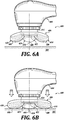
- FIGURES 6A and 6B depict, respectively, an unloaded condition and a loaded condition of a system 600 against a portion of skin 602.
- the system includes an appliance 604 coupled to an end effector 606.
- the end effector 606 includes a plurality of contact points 608.
- the plurality of contact points 608 are located a distance from each other based on an inverse of a stimulation frequency.
- Each of the plurality of contact points 608 is located on one of a plurality of contact areas 610.
- the end effector has a central portion 612 located between the plurality of contact areas 610.
- the end effector 606 is coupled to appliance 604 via a central support 614 that is located opposite of the central portion 612.
- the portions of the end effector 606 that include the contact areas 610 are cantilevered out away from the central support 614.
- the system 600 is in an unloaded state (i.e., the end effector 606 is not in contact with the portion of skin).
- the appliance includes a motor that moves the end effector 606.
- the motor imparts oscillating movements to the end effector 606 about an axis 616.
- the system 600 has an oscillating frequency based on a desired stimulation frequency.
- the stimulation frequency is selected based on an anti-aging effect stimulated by a cyclical stimulus within the portion of skin at the stimulation frequency.
- the end effector 606 has a cupped shape where the contact points 608 are located closer to the portion of skin 602 than the central portion 612. From the point shown in FIGURE 6A , as the system 600 is lowered to the portion of skin 602, the contact points 608 are the first potions of the system 600 to contact the portion of skin 608.
- a force 618 is applied to the system 600 to bias the end effector 606 toward the portion of skin 602.
- the force 618 applied to the system 600 is in a range from about 85 grams-force (approximately 0.83 N) to about 100 grams-force (approximately 0.98 N).
- the force 618 applied to the system 600 causes the cantilevered portions of the end effector 606 to deflect toward the appliance 604. Such a deflection of the cantilevered portions is possible, in some examples, because the cantilevered portions of the end effector 606 are made of a non-rigid material.
- the force 618 does not cause the central portion 612 to touch the portion of skin 602.
- the contact areas 610 remain in contact with the portion of skin 602 when the force 618 is applied. Any contact of the end effector 606 with the portion of skin 602, other than the contact between the contact areas 610 and the end effector 606, may disrupt any cyclical stimulus of the portion of skin 602 by the end effector 606.
- the operating motor of the appliance 604 continues to move the end effector 606.
- the movement of the end effector 606 when the force 618 is applied to the system 600 produces a cyclical stimulus within the portion of skin 602 at about the stimulation frequency.
- the cyclical stimulus is a wave-based mechanical strain that propagates through the portion of skin 602.
- the location of the plurality of contact points 608 i.e., at a distance from each other based on an inverse of a stimulation frequency
- encourages propagation of the cyclical stimulus because the cyclical stimulus created by each of the plurality of contact points 608 is in phase with the other(s) of the plurality of contact points 608.
- one of the plurality of contact points 608 does not cancel out the cyclical stimulus created by another one of the plurality of contact points 608.
- FIGURES 7A through 7F depict embodiments of contact areas and examples of results of the embodiments of contact areas on skin displacement.
- the contact areas depicted in FIGURES 7A through 7F are capable of being used with embodiments of end effectors described here.
- the contact areas of an end effector are usable to apply treatment compositions to a portion of skin.
- the treatment compositions described herein are one or more of a cosmetic composition (e.g., makeup, foundation, bronzer, etc.), a medical ointment (e.g., antibacterial ointment, hydrocortisone cream, etc.), a cleanser (e.g., soap, makeup remover, etc.), or any other composition that is capable of being applied to a portion of skin.
- a treatment composition is a liquid, a non-Newtonian substance, a gel, or any other type of composition.
- FIGURE 7A depicts a side view of an embodiment of a contact area 700.
- the contact area includes a smooth face 702 and a rounded shoulder 704.
- the smooth face 702 includes a contact location that is configured to contact a portion of skin.
- the rounded shoulder 704 has a radius that does not provide a noticeable edge to the face 702.
- FIGURE 7B depicts a chart showing an example of skin displacement ⁇ 1 of a portion of skin over time when the portion of skin is in contact with the contact area 700 and the contact area 700produces a cyclical stimulus within the portion of skin.
- FIGURE 7C depicts a side view of an embodiment of a contact area 706.
- the contact area includes a smooth face 708 and a rounded shoulder 710.
- the smooth face 708 when used in an end effector with a plurality of contact areas, includes a contact location that is configured to contact a portion of skin.
- the rounded shoulder 710 has a radius that provides a noticeable edge to the face 708. In the embodiments shown in FIGURES 7A and 7C , the radius of the rounded shoulder 710 is less than the radius of the rounded shoulder 704.
- FIGURE 7D depicts a chart showing an example of skin displacement ⁇ 2 of a portion of skin over time when the portion of skin is in contact with the contact area 706 and the contact area 706 produces a cyclical stimulus within the portion of skin.
- the cyclical stimuli shown have the same frequency, but the skin displacement ⁇ 2 using the rounded shoulder 710 on the contact area 706 is greater than the skin displacement ⁇ 1 using the rounded shoulder 704 on the contact area 700.
- the greater skin displacement ⁇ 2 is due to the greater friction between the portion of skin and the noticeable edge provided by the rounded shoulder 710 on the face 708.
- FIGURES 7E and 7F depict cross-sectional views of two embodiments of contact areas with slits across faces of the contact areas.
- FIGURE 7E depicts a cross-sectional view of a contact area 712 that has a face 714.
- the contact area 712 also has two slits 716 across the face 714. While the embodiment of contact area 712 has two slits, in other embodiments, contact areas have other numbers of slits, such as one slit across the face. Between the two slits 716, a portion 718 of the contact area 712 returns back to approximately the same level of the face 714.
- the recesses in the face 714 created by the slits 716 are capable of containing treatment composition as the contact area 712 is moved across a portion of skin. In this way, the recesses in the face 714 created by the slits 716 function as a small reservoir to more evenly spread treatment composition across a portion of skin.
- the slits 716 also provide distinct edges on the face 714 that provide greater friction between the contact area 712 and the portion of skin to cause greater skin displacement in the portion of skin.
- FIGURE 7F depicts a cross-sectional view of a contact area 720 that has a face 722.
- the contact area 720 also has two slits 724 across the face 722. While the embodiment of contact area 722 has two slits, in other embodiments, contact areas have other numbers of slits, such as one slit across the face. Between the two slits 724, a portion 726 of the contact area 720 is raised above the deepest parts of the two slits 724, but is recessed back from the level of the face 722. The recess in the face 722 created by the slits 724 and the recessed portion 726 is capable of containing treatment composition as the contact area 720 is moved across a portion of skin.
- the recess in the face 722 created by the slits 724 and the recessed portion 726 functions as a small reservoir to more evenly spread treatment composition across a portion of skin.
- the recess in the face 722 created by the slits 724 and the recessed portion 726 also provides friction between the contact area 720 and the portion of skin to cause greater skin displacement in the portion of skin.
- FIGURES 7G and 7H depict side views of embodiments of contact areas with surface texturing on their faces.
- FIGURE 7G depicts a side view of a contact area 728.
- the contact area 728 includes a face 730 with surface texturing in the form of dimples 732 on the face 730.
- FIGURE 7H depicts a side view of a contact area 734.
- the contact area 734 includes a face 736 with surface texturing in the form of linear bumps 738 on the face 736.
- other forms of surface texturing are used on the faces of contact areas. Examples of the benefits of surface texturing on the face of a contact area include one or more of better application of treatment composition into a portion of skin, greater skin displacement by the contact area, or improved sensation of the operation of the contact area against the portion of skin.
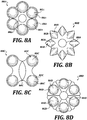
- FIGURES 8A through 8D depict top views of embodiments of end effectors with different numbers and arrangements of contact areas.
- Each of FIGURES 8A through 8D depicts a top view of an end effector 800A-D.
- Each end effector 800A-D includes a plurality of contact points 802A-D.
- Each of the contact points 802A-D is located on one of a plurality of contact areas 804A-D.
- Each end effector 800A-D also includes a central portion 806A-D that is recessed away from the contact areas 804A-D such that the contact points 802A-D are the first portions of the end effectors 800A-D that would contact a portion of skin.
- the end effectors 800A-D have different numbers and arrangements of contact areas 804A-D. More specifically, as depicted in FIGURE 8A , the end effector 800A has a flower arrangement with a circular central portion 806A and six circular contact areas 804A around the circular central portion 806A. As depicted in FIGURE 8B , the end effector 800B has an arrangement that is a variation of a flower arrangement. The end effector 800B has a circular central portion 806B and eight pointed contact areas 804B around the circular central portion 806B. As depicted in FIGURE 8C , the end effector 800C has a butterfly arrangement with a central portion 806C with a vesica piscis shape and four contact areas 804C.
- the four contact areas 804C are arranged with two sets of two contact areas 804C on each side of the central portion 806C.
- the end effector 800D has a pie-shaped arrangement with a circular central portion 806B and six pie-piece-shaped contact areas 804D around the circular central portion 806D. Many other variations on the number and arrangement of contact areas on an end effector are possible.
- Each of the embodiments of end effectors 800A-D depicted in FIGURES 8A through 8D include a plurality of contact points 802A-D.
- the contact points 802A-D are located at a target distance from each other that is based on an inverse of the stimulation frequency. It may not be possible to locate four or more contact points equidistantly from each other. For example, with four contact points located at corners of a square, a contact point may be equidistantly located from the other contact points at neighboring corners, but will not be equidistantly located from the contact point that is across the diagonal of the square.
- four or more contact points may be located at a target distance from each other that is based on an inverse of the stimulation frequency.
- the four or more contact points may be located at a target with respect to each other such that the individual ones of the four or more contact points do not cancel out cyclical stimulus generated by the others of the four or more contact points.
- FIGURES 9A through 9C depict, respectively, perspective, side, and exploded views of an end effector 900.
- the end effector 900 includes an end portion 902 and a base portion 904.
- the end portion 902 of the end effector 900 has a plurality of contact points 906.
- Each of the plurality of contact points 906 is located on one of a plurality of contact areas 908.
- the contact points 906 are located at a target distance from each other that is based on an inverse of a stimulation frequency.
- the base portion 904 includes a drive assembly 910 that is configured to be engaged to a drive hub of an appliance.
- the base portion 904 is coupled to the end portion 902 via a central support 912.
- the contact areas 908 are located on the end portion 902 such that the contact areas 908 are cantilevered out from the central support 912.
- the end effector 900 also includes a dispenser 914 located in a central portion 916 of the end portion 902 of the end effector 900.
- the dispenser 914 is located on a different location of the end portion 902, such as one of the plurality of contact points 906.
- the ball dispenser 914 does not extend away from the central portion 916 as far as the plurality of contact points 906 extend away from the central portion 916. In this way, in one example, the plurality of contact points 906 are biased toward a portion of skin when a first force is applied to the end effector 900 without the ball dispenser 914 touching the portion of skin.
- a cyclical stimulus is produced within the portion of skin at about a stimulation frequency.
- a second force that is greater than the first force
- the ball dispenser 914 touches the portion of skin.
- the ball dispenser 914 when the ball dispenser 914 touches the portion of skin, the ball dispenser 914 dispenses a treatment composition to the portion of skin.
- the treatment composition is located within the base portion 904, such as within at least the central support 912.
- the ball dispenser 914 rolls, causing some of the treatment composition located within the base portion 904 to be dispensed to the portion of skin.
- the contact areas 906 apply the dispensed treatment composition over the surface of the portion of skin.
- end effector 900 depicted in FIGURES 9A to 9C includes a ball dispenser 914.
- ball dispensers are not the only type of dispensers that are capable of being used with end effectors.
- end effectors include treatment composition dispensers other than ball dispensers to dispense treatment composition to a portion of skin.
- Embodiments of systems described herein with motors coupled to end effectors are capable of being used to perform a method 1000 depicted in FIGURE 10 .
- operation of the motor is activated.
- the motor is located within an appliance and the motor is activated by a user input received by the appliance via one or more user input mechanisms.
- motion is imparted from the motor to the end effector.
- the motor is operatively coupled to a drive hub that engages a drive assembly of the end effector, and the operation of the motor moves the end effector in an oscillating manner.
- operation of the motor causes the system to have an oscillating frequency based on the stimulation frequency.
- a force is applied to the end effector to bias the end effector toward the portion of skin such that a plurality of contact points of the end effector contact the portion of skin.
- the plurality of contact points are located at a distance from each other that is based on an inverse of the stimulation frequency.
- the combination of the motor operating and the force being applied to bias the end effector toward the portion of skin causes the end effector to produce a cyclical stimulus within the portion of skin at about the stimulation frequency.
- the method 1000 includes additional steps described herein that are not depicted in FIGURE 10 .
- the method 1000 includes applying a composition configured to treat a condition of the portion of skin.
- the method 1000 includes applying a composition configured to treat a condition of the portion of skin.
- the method 1000 includes selecting the stimulation frequency based on the condition of the portion of skin.
- FIGURES 11A and 11B depict side and top views, respectively, of end effector 1100.
- the end effector 1100 includes contact points 1102 located on contact areas 1104.
- the end effector 1100 also includes a central support 1110.
- the end effector 1100 is configured to be moved linearly along path 1120 in a direction parallel to the z-axis.
- the end effector 1100 is configured to be moved in an oscillatory motion 1122 in the x-y plane about the z-axis.
- the end effector 1100 is moved along the path 1120 and/or in the oscillatory motion 1122 by an appliance (e.g., appliance 302 or appliance 402) coupled to the central support 1110 of the end effector 1100.
- an appliance e.g., appliance 302 or appliance 402
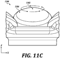
- FIGURES 11C depicts a side view of a portion of the end effector 1100 with one of the contact points 1102.
- the depicted contact point 1102 moves in a resultant motion 1124.
- the resultant motion 1124 is a complex motion as a result of the combination of oscillatory movement of the end effector 1100 about the z-axis and tapping motion of the end effector 1100 in the z-axis direction.
- the velocity of the oscillatory movement of the end effector 1100 about the z-axis is greater than the velocity of the linear motion of the end effector 1100 in the z-axis direction.
- the frequency of the oscillatory movement of the end effector 1100 about the z-axis and the frequency of the tapping motion of the end effector 1100 in the z-axis direction are selected to enact an oscillating frequency mode (sometimes referred to as "harmonics").
- the resultant motion 1124 of the end effector 1100 produces a cyclical stimulus within a portion of skin of a user at about a target stimulation frequency (e.g. the oscillating frequency).
- the oscillating frequency mode is present with low dampening.
- the oscillating frequency mode of the end effector 1100 increases penetration of formulation into the portion of skin.
- the end effector 1100 includes one or more features that add to the complex motion and/or oscillating frequency mode.
- the end effector 1100 includes one or more of a hollow elastomer shaft, an elastomer diaphragm, a ball in socket, or an axial spring which itself may or may not resonate. Any of these features may be used alone or in combination with frequency selection of the oscillatory movement of the end effector 1100 about the z-axis and/or the linear motion of the end effector 1100 in the z-axis direction to produce a desired oscillating frequency mode.
- any of the illustrative examples not falling under the scope of the claims of end effectors described herein may be modified to include a singular end effector in place of the plurality of contact points.
- a top view and a side view of an illustrative example not falling under the scope of the claims of an end effector 1200 with a singular contact point 1202 are depicted, respectively, in FIGURES 12A and 12B .
- the contact point 1202 is located on a contact area 1204.
- the singular contact point 1202 is located an offset distance 1206 away from the center of the end effector 1206.
- the contact area 1204 is fastened to a central portion 1208 of the end effector 1200 using mechanical fasteners.
- the contact area 1204 is otherwise coupled to the central portion 1208, such as via an adhesive, via molding, or via any other coupling mechanism.
- the contact area 1204 is molded together with the central portion 1208 as a single piece.
- the single applicator point may be operated at an oscillating frequency corresponding to a stimulation frequency for mechanobiological effects independent of end effector geometry.
- each contact point will create a wave that propagates in the skin. These two waves will meet and, if the contact points are properly geometrically spaced from each other, their waves will not cancel out. However, if the contact points are not properly geometrically spaced, their waves could cancel.
- a singular point end effector (e.g., end effector 1200) is independent of this constraint to be geometrically spaced with respect to other contact points, and thus can be placed at any offset (e.g., offset 1206) relative to the center of motion or oscillation since only one wave is being created and there is no competing wave to cancel against it.
- any of the embodiments disclosed herein are capable of being used with a plurality of contact points are located at a target distance from each other that is based on an inverse of a target stimulation frequency.
- the contact points 102 of end effector 100 could be replaced by a singular contact point (e.g., the singular contact point 1202 of the end effector 1200).
- terminology such as “upper,” “lower,” “vertical,” “horizontal,” “inwardly,” “outwardly,” “inner,” “outer,” “front,” “rear,” etc. should be construed as descriptive and not limiting the scope of the claimed subject matter.
Landscapes
- Health & Medical Sciences (AREA)
- Life Sciences & Earth Sciences (AREA)
- Epidemiology (AREA)
- Pain & Pain Management (AREA)
- Physical Education & Sports Medicine (AREA)
- Rehabilitation Therapy (AREA)
- Animal Behavior & Ethology (AREA)
- General Health & Medical Sciences (AREA)
- Public Health (AREA)
- Veterinary Medicine (AREA)
- Dermatology (AREA)
- Percussion Or Vibration Massage (AREA)
- Massaging Devices (AREA)
Description
- The present application is related to U.S. Patent Application No.
U.S. Patent Application No. 14/587587, filed December 31, 2014 U.S. Patent Application No. 14/588,209, filed December 31, 2014 U.S. Patent Application No. 14/588,230, filed December 31, 2014 U.S. Patent Application No. 14/588,255, filed December 31, 2014 -
US 2013/0138023 relates to a device for massaging or treating the muscles of the back and neck of a patient. - Document
US-A1-2008/0262397 discloses a system for stimulating a portion of skin at a stimulation frequency, the system comprising: an appliance having a motor; and an end effector operably coupled to the motor, the end effector including a plurality of contact points at which the end effector is configured to contact the portion of skin. - This summary is provided to introduce a selection of concepts in a simplified form that are further described below in the Detailed Description. This summary is not intended to identify key features of the claimed subject matter, nor is it intended to be used as an aid in determining the scope of the claimed subject matter.
- In one embodiment, a system for stimulating a portion of skin at a stimulation frequency includes an appliance having a motor and an end effector operably coupled to the motor. The end effector includes a plurality of contact points at which the end effector is configured to contact the portion of skin. The plurality of contact points are located at a target distance from each other that is based on an inverse of a target stimulation frequency. The motor is configured to move the end effector such that, when the motor is operating, the system has an oscillating frequency based on the target stimulation frequency. When the motor is operating and a force is applied to the system to bias the end effector toward the portion of skin, the end effector produces a cyclical stimulus within the portion of skin at about the target stimulation frequency.
- In one example, the end effector includes a cup-shaped end configured such that the plurality of contact points are the only portions of the end effector to contact the portion of skin when the force is applied from the end effector to the portion of skin. In another example, the motor is configured to impart one or more of oscillatory motion or vibrational motion, and the end effector is configured to impart cyclical mechanical strain to the skin. In another example, the end effector includes a base portion and an end portion. In another example, the base portion has a mass selected such that the system has an oscillating frequency at about the target stimulation frequency when the motor is operating. In another example, the end portion includes the plurality of contact points, and wherein the end portion is connected to the base portion via a central support such that the plurality of contact points are cantilevered away from the central support. In another example, the end effector is releasably couplable to the appliance, the end effector includes a drive assembly that engages a drive hub of the appliance when the end effector is releasably coupled to the appliance, and the motor is operatively coupled to the drive hub such that operation of the motor causes movement of the drive hub that is transferred to the drive assembly to move the end effector.
- In another embodiment, an end effector for stimulating a portion of skin at a stimulation frequency includes a base portion that is couplable to a motor and an end portion having a plurality of contact points at which the end effector is configured to contact the portion of skin. The plurality of contact points are located at a target distance from each other that is based on an inverse of the stimulation frequency. The end effector is configured such that, when the base portion is coupled to the motor and the motor is operating, the end effector has an oscillating frequency based on the stimulation frequency. When the motor is operating and a force is applied to bias the end effector toward the portion of skin, a cyclical stimulus is produced within the portion of skin at about the stimulation frequency.
- In one example, the end portion has the plurality of contact points and the plurality of contact points includes at least three contact points arranged equidistantly from each other. In another example, a distance between each set of two of the three contact points is a whole integer increment of the inverse of the stimulation frequency. In another example, the end portion has the plurality of contact points and each of the plurality of contact points is located on one of a plurality of pads and edges of each of the plurality of pads has a rounded shoulder. In another example, the end portion has the plurality of contact points and each of the plurality of pads has at least one of a rounded shoulder, at least one slit across a face of the pad, or surface texturing on a face. In another example, a surface of the end portion has a hardness in a range from about 10 Shore A to about 90 Shore A. In another example, a surface of the end portion includes a rigid material. In another example, the end effector includes a ball dispenser configured to dispense a treatment composition to the portion of skin in response to the ball dispenser coming into contact with the portion of skin. In another example, the stimulation frequency is in a range from about 65 Hz to about 120 Hz. In another example, the force applied from the end effector to the portion of skin is in a range from about 20 grams-force to about 500 grams-force.
- In another embodiment, a method of treating a portion of skin at a stimulation frequency using an appliance comprising a motor coupled to an end effector includes driving at an oscillating frequency an end effector having a plurality of contact points located at a distance from each other that is based on an inverse of a target stimulation frequency and inducing a cyclical stimulus at about the target stimulation frequency within a portion of skin contacted by the plurality of contact points.
- In one example, the method further includes applying a composition to the portion of skin using the end effector while driving the end effector at the oscillating frequency. In another example, applying the composition includes applying a composition configured to treat a condition of the portion of skin. In another example, driving the end effector at the oscillating frequency includes selecting the target stimulation frequency based on the condition of the portion of skin.
- The foregoing aspects and many of the attendant advantages of the disclosed subject matter will become more readily appreciated as the same become better understood by reference to the following detailed description, when taken in conjunction with the accompanying drawings, wherein:
-
FIGURES 1A ,1B and1C depict, respectively, a perspective view, a side view, and a top view of an embodiment of an end effector; -
FIGURES 2A and2B depict perspective views of another embodiment of an end effector that includes an end portion and a base portion; -
FIGURE 3 depicts an embodiment of a system that includes an appliance and an end effector, in accordance with embodiments of end effectors described herein; -
FIGURE 4 depicts another embodiment of a system that includes an appliance and an end effector, in accordance with embodiments of end effectors described herein; -
FIGURE 5 depicts, in block diagrammatic form, an example of an operating structure of an appliance, in accordance with embodiments of appliances described herein; -
FIGURES 6A and 6B depict, respectively, an unloaded condition and a loaded condition of an embodiment of a system with an appliance and an end effector against a portion of skin; -
FIGURES 7A through 7H depict embodiments of contact areas that are usable with embodiments of end effectors described herein and examples of results of the embodiments of contact areas on skin displacement; -
FIGURES 8A through 8D depict top views of additional embodiments of end effectors with different numbers and arrangements of contact areas; -
FIGURES 9A, 9B and9C depict, respectively, perspective, side, and exploded views of an embodiment of an end effector with a ball dispenser; -
FIGURE 10 depicts an embodiment of a method that is capable of being performed using embodiments of systems described herein with motors coupled to end effectors; -
FIGURES 11A ,11B , and11C depict, respectively, side, top, and partial side views of an embodiment of an end effector and complex movements thereof; and -
FIGURES 12A and 12B depict, respectively, a top view and a side view of an illustrative example not falling under the scope of the claims of an end effector with a singular contact point. - Various forms of energy input into biological organisms have different effects on the biological organisms. These forms of energy input include mechanical inputs, thermal inputs, electromagnetic inputs, electrical inputs, acoustic inputs, and the like. One particular field of study, known as mechanobiology, aims to understand how physical forces and changes in cell or tissue mechanics affect biological organisms.
- Under certain conditions, mechanical stimuli (e.g., applied cyclical strain, mechanical motion, applied strain, and the like) input to a portion of skin of a biological organism causes an increase in biomarker (e.g., protein) production. In one example, a number of proteins within the skin can be regulated using, among other things, cyclical mechanical strain applied at particular frequencies using an end effector. The disclosed embodiments employ technologies and methodologies that stimulate frequency response of cells in the dermis and epidermis to induce production of proteins associated with young, healthy skin. Human skin cells (dermal fibroblasts in particular) respond to strain in tissue with cytoskeletal reordering and increased production in extracellular matrix proteins. In an embodiment, by combining discrete, differential strain in the skin at specific frequencies, the disclosed technologies and methodologies induce increased growth and repair activities from multiple cell types found in the skin, thereby producing an anti-aging effect. Depending on the particular location of the portion of skin in a biological organism, mechanical motion or strain generated in a range from about 65 Hz to about 120 Hz may stimulate anti-aging effects.
- In an embodiment, the cumulative effects of applying cyclical mechanical strain as disclosed include one or more anti-aging effects. For example, by applying a particular stress to the skin, cutaneous cells will react to the stress by upregulating (increasing) production of certain proteins. The character and duration of the stress will affect which proteins are upregulated and to what extent. As a non-limiting example of the benefits achievable, certain disclosed embodiments can be used to upregulate the production of integrin in the skin, which results in anti-aging effects by increasing epidermal cohesion.
- The following discussion provides examples of systems, apparatuses, and methods for implementing technologies and methodologies for stimulating a portion of skin at a stimulation frequency in order to improve skin health through upregulating production of certain proteins within the portion of skin. In an embodiment, an end effector with a plurality of contact points is used for stimulating a portion of skin at a stimulation frequency where the contact points are located a target distance from each other that is based on an inverse of the stimulation frequency. In an embodiment, a system for stimulating a portion of skin at a stimulation frequency includes an appliance and an end effector with a plurality of contact points that are located a distance from each other that is based on an inverse of the stimulation frequency. In an embodiment, a method for stimulating a portion of skin at a stimulation frequency includes activating operation of a motor to impart movement to an end of an end effector and applying a force to bias the end effector toward the portion of skin to cause a cyclical stimulus of the portion of skin at about the stimulation frequency. Examples of cyclical stimuli include cyclical mechanical strain induced in the portion of skin, cyclical pressure waves induced into the portion of skin, and the like.
- In the following description, numerous specific details are set forth in order to provide a thorough understanding of one or more embodiments of the present disclosure. It will be apparent to one skilled in the art, however, that many embodiments of the present disclosure may be practiced without some or all of the specific details. In some instances, well-known process steps have not been described in detail in order not to unnecessarily obscure various aspects of the present disclosure. Further, it will be appreciated that embodiments of the present disclosure may employ any combination of features described herein.
- An embodiment of an
end effector 100 is depicted inFIGURES 1A to 1C . Theend effector 100 includes contact points 102. In an embodiment, contact points 102 can take a variety of shapes, configurations, and geometries including spheroidal, polygonal, cylindrical, conical, planar, parabolic, as well as regular or irregular forms. In illustrative examples not falling under the scope of the claims as discussed below with respect toFIGURES 12A and 12B , theend effector 100 includes a singular contact point that is located an offset distance away from the center of theend effector 100. - The
end effector 100 also includescontact areas 104. Each of the contact points 102 is located on one of thecontact areas 104. In an embodiment, the contact points 102 are located atarget distance 106 away from each other. For example, in an embodiment, the contact points 102 are located atarget distance 106 away from each other determined from the inverse of the stimulation frequency. In the particular embodiment shown inFIGURES 1A to 1C , the contact points 102 include the contact points that are equidistant from each other (i.e., thedistances 106 between contact points 102are all about the same, such as being within ±5% of each other). Theend effector 100 includes acentral portion 108 located between thecontact areas 104.FIGURES 1A to 1C depict a coordinate system with X-, Y-, and Z-directions. In the Z-direction, thecentral portion 108 is depressed from thecontact areas 104 such that the contact points 102 of thecontact areas 104 are the points at which thecontact areas 104 would contact a flat object lowered in the Z-direction. - The
end effector 100 includes acentral support 110 on the opposite side of thecentral portion 108. As is seen inFIGURE 1B , thecontact areas 104 are located on portions ofend effector 100 that are cantilevered out from thecentral support 110. In some embodiments, thecontact areas 104 have a surface quality configured to impart a cyclical mechanical strain to the skin (i.e., stainless steel, plastic, filaments, etc.) In one embodiment, theend effector 100 is made of a non-rigid material. Some examples of non-rigid materials include plastics (e.g., polyurethane, silicones), elastomeric materials (e.g., thermoplastic elastomers), rubber materials (e.g. thermoplastic vulcanized rubber, natural rubber), and any combinations thereof. In one example, the non-rigid material of theend effector 100 has a hardness in a range from about 10 Shore A to about 90 Shore A, as defined by the American Society for Testing and Materials (ASTM) standard D2240. When theend effector 100 is made of a non-rigid material and thecontact areas 104 are located on portions ofend effector 100 that are cantilevered out from thecentral support 110, the portions ofend effector 100 with thecontact areas 104 have a spring-like quality that permits some movement of thecontact areas 104 in the Z-direction. - Alternatively, in some embodiments, the
end effector 100 is made of a rigid material (e.g., stainless steel, hard plastic, filaments, carbon fiber, etc.). In some embodiments, theend effector 100 is made from a combination of rigid and non-rigid materials. In one example, a structural portion of the end effector 100 (e.g. an interior of the end effector 100) is made of a rigid material and the portion of theend effector 100 that contacts the skin is made of a non-rigid material. In other embodiments, theend effector 100 is made from one or more of an anti-bacterial material or an anti-microbial material. The anti-bacterial material or the anti-microbial may be variations of any of the materials described herein (e.g., rigid materials, non-rigid materials). - In the embodiment shown in
FIGURES 1A and1C , theend effector 100 includes fastener holes 112. In one embodiment, mechanical fasteners (e.g., screws, bolts, rivets, etc.) are placed in the fastener holes 112 to mechanically fasten theend effector 100 to another component. In other embodiments, theend effector 100 is molded onto an attachment base (e.g., using a second shot injection molding process). In other embodiments, theend effector 100 is bonded (e.g., mechanically and/or chemically) with an adhesive onto an attachment base. In one embodiment, theend effector 100 is couplable to a motor that is configured to move the end effector. In one example, when theend effector 100 is couplable to a motor and the motor is operating, the motor oscillates theend effector 100 with rotational movements about an axis in the Z-direction. - In one embodiment, the
end effector 100 is used to stimulate a portion of skin at a stimulation frequency. In one embodiment, theend effector 100 is used to induce a cyclical response within a portion of skin at a target frequency. In one embodiment, theend effector 100 is used to apply a cyclical mechanical strain to a portion of skin responsive to an applied potential. In an embodiment, theappliance 302 is configured to manage a duty cycle and frequency associated with driving an end effector. For example, in an embodiment, theappliance 302 includes circuitry configured to manage a duty cycle and frequency associated with driving an end effector. - In one example, the stimulation frequency is selected based on a condition of the portion of skin. For example, the stimulation frequency is selected based on an anti-aging effect that is activated by cyclical mechanical strain of the portion of skin at the stimulation frequency. The contact points 102 are located at a target distance from each other based on an inverse of the stimulation frequency. For example, with a stimulation frequency of 65 Hz, the inverse of the stimulation frequency (i.e., the period) is 0.0167 seconds per cycle. With a wave propagation speed of 2.0 meters per second, the wavelength is 0.0333 meters per second, or 3.33 cm per second. Other examples of wavelength distances based on frequency are shown in TABLE 1.
Table 1 - Example wavelength distances based on frequency Frequency (f) Hz (cycle/sec) Period (T) (sec/cycle) Speed1 (v) (m/s) Wavelength (λ) (m/cycle) Wavelength (λ) (cm/cycle) 60 0.0167 2.0 0.0333 3.33 65 0.0154 2.0 0.0308 3.08 70 0.0143 2.0 0.0286 2.86 75 0.0133 2.0 0.0267 2.67 80 0.0125 2.0 0.0250 2.50 85 0.0118 2.0 0.0235 2.35 90 0.0111 2.0 0.0222 2.22 95 0.0105 2.0 0.0211 2.11 100 0.0100 2.0 0.0200 2.00 105 0.0095 2.0 0.0190 1.90 110 0.0091 2.0 0.0182 1.82 115 0.0087 2.0 0.0174 1.74 120 0.0083 2.0 0.0167 1.67 1 The speed of sound in skin is approximately 2.0 m/s. - In one embodiment, the contact points 102 are located at a distance from each other that is a whole integer increment of the inverse of the stimulation frequency. Using the 65 Hz example above, one whole integer increment of the inverse of the stimulation frequency is 3.08 cm. Thus, in this 65 Hz example, the
distances 106 between the contact points 102 are 3.08 cm. Using another example with a 110 Hz stimulation frequency, the wavelength is 1.82 cm per second. One whole integer increment of the inverse of the stimulation frequency is 3.64 cm. Thus, in this 100 Hz example, thedistances 106 between the contact points 102 are 3.64 cm. Many other examples of frequencies and whole integer increments of the inverse of the frequencies are possible. - Another embodiment of an
end effector 200 is depicted inFIGURES 2A and2B . Theend effector 200 includes anend portion 202 and abase portion 204. Theend portion 202 includes contact points 206 andcontact areas 208. Each of the contact points 206 is located on one of thecontact areas 208. Thebase portion 204 includes adrive assembly 210 that is configured to engage a drive hub of an appliance (not shown). In one example, the appliance includes a motor that is operatively coupled to the drive hub. When theend effector 200 is releasably coupled to the appliance and thedrive assembly 210 is engaged to the drive hub, operation of the motor causes movement of the drive hub that is transferred to the drive assembly to move the end effector. - As depicted in
FIGURE 2A , theend portion 202 of theend effector 200 is connected to thebase portion 204 of theend effector 200 via acentral support 212. Thecontact areas 206 are located on portions of theend portion 202 that are cantilevered out from thecentral support 212. In one embodiment, theend portion 202 is made of a non-rigid material and thecontact areas 208 and the portions of theend portion 202 with thecontact areas 208 have a spring-like quality that permits some movement of thecontact areas 208. In one example, some or all of thebase portion 204 is made of a rigid material. In this example, the portions of theend portion 202 with thecontact areas 208 retain their spring-like quality even though some or all of thebase portion 204 is made of a non-rigid material. - When the
end effector 200 is coupled to a motor and the motor is operating, the system of theend effector 200 and the motor has a resonance frequency. The resonance frequency of the system is a function of characteristics of the system, such as operational parameters of the motor, mass of the motor, and mass of theend effector 200. In one embodiment, theend effector 200 is designed to be driven by a specific motor to stimulate a portion of skin at a stimulation frequency. In one example, the mass of theend effector 200 is selected such that the system of theend effector 200 and the specific motor has a resonance frequency based on the stimulation frequency. Selecting the mass of theend effector 200, in one example, includes selecting a mass of one or more of theend portion 202 or thebase portion 204. In one example of a resonance frequency based on the stimulation frequency, the resonance frequency is approximately the same as the stimulation frequency. In other examples of resonance frequency based on the stimulation frequency, the resonance frequency is a whole integer increment of the stimulation frequency. -
FIGURE 2B depicts theend effector 200 that also includes acoupling ring 214. Thecoupling ring 214 is configured to couple theend effector 200 to another object, such as an appliance that includes a motor. Examples of end effectors coupled to appliances that include motors are described in greater detail below. - Embodiments of end effectors described herein are usable in a system, such as the
system 300 depicted inFIGURE 3 . Thesystem 300 includes anappliance 302 and anend effector 304. Theappliance 302 depicted inFIGURE 3 is in the form of a handle; however, theappliance 302 can take any number of other forms. Theappliance 302 includes adrive hub 306. Theappliance 302 includes a motor (not shown) that is operatively coupled to thedrive hub 306 such that operation of the motor causes movement of thedrive hub 306. Theappliance 302 includes one or moreuser input mechanisms 308. In one embodiment, operation of the motor is based on user inputs received by the one or moreuser input mechanisms 308. In some examples, user input received by the one or moreuser input mechanisms 308 cause one or more of initiating operation of the motor, changing an operating characteristic of the motor, and ceasing operation of the motor. - In an embodiment, the
end effector 304 depicted inFIGURE 3 includes anend portion 310 and abase portion 316. The end portion includes a plurality of contact points 312. In one embodiment, the plurality of contact points 312 are located a distance from each other based on an inverse of a stimulation frequency. Each of the plurality of contact points 312 is located on one of a plurality ofcontact areas 314. Thebase portion 316 is coupled to theend portion 310 via acentral support 318. The base portion includes adrive assembly 320 that is configured to engage thedrive hub 306 of theappliance 302. - In an embodiment, the
end effector 304 is physically coupleable to theappliance 302. When theend effector 304 is coupled to theappliance 302, thedrive assembly 320 of theend effector 304 is engaged to thedrive hub 306 of theappliance 302 such that operation of the motor of theappliance 302 causes movement of thedrive hub 306 that is transferred to thedrive assembly 320 of theend effector 304 to move the end effector. In one embodiment, operation of the motor imparts oscillating movement to theend effector 304 with an amount of inertia to move theend effector 304 at a target frequency and amplitude. In one example, the motor is configured to drive theend effector 304 at a frequency in a range from about 65 Hz to about 120 Hz. In another example, the motor is configured to drive theend effector 304 at an angular amplitude in a range from about 1° to about 16° of peak-to-peak motion. Such oscillating movement of theend effector 304, when applied to a portion of skin, produces a cyclical stimulus within the portion of skin at about the stimulation frequency. In some examples, the oscillating frequency is about the stimulation frequency. In other examples, the oscillating frequency is different from the stimulation frequency. In one example, the cyclical stimulus is a cyclical mechanical strain at the stimulation frequency which stimulates certain anti-aging effects of a target biomarker. - In an embodiment, the
end effector 304 is communicatively coupled to theappliance 302 via one or more communication interfaces. - Another example of a
system 400 with anappliance 402 and anend effector 404 is depicted inFIGURE 4 . Theappliance 402 depicted inFIGURE 4 is in the form of a hand-held appliance that is intended to be held against the palm of a user's hand with the user's fingers grasped around theappliance 402. While theappliance 402 is in the form of a hand-held appliance, theappliance 402 can take any number of other forms. Theappliance 402 includes adrive hub 406. Theappliance 402 includes a motor (not shown) that is operatively coupled to thedrive hub 406 such that operation of the motor causes movement of thedrive hub 406. Theappliance 402 includes one or moreuser input mechanisms 408. In one embodiment, operation of the motor is based on user inputs received by the one or moreuser input mechanisms 408. In some examples, user input received by the one or moreuser input mechanisms 408 cause one or more of initiating operation of the motor, changing an operating characteristic of the motor, and ceasing operation of the motor. - The
end effector 404 depicted inFIGURE 4 includes anend portion 410 and abase portion 416. The end portion includes a plurality of contact points 412. In one embodiment, the plurality of contact points 412 are located a distance from each other based on an inverse of a stimulation frequency. Each of the plurality of contact points 412 is located on one of a plurality ofcontact areas 414. Thebase portion 416 is coupled to theend portion 410 via acentral support 418. The base portion includes adrive assembly 420 that is configured to engage thedrive hub 406 of theappliance 402. - In one embodiment, the
end effector 404 is usable interchangeably with bothappliance 302 andappliance 402. In other words, in this particular example, thedrive assembly 420 ofend effector 404 is separately engagable with both thedrive hub 306 ofappliance 302 and thedrive hub 406 ofappliance 402. In one embodiment, theappliance 302 and theappliance 402 have different characteristics, such as different motor sizes, different motor inertias, etc. In such a case, the system with theend effector 404 and theappliance 302 has a different oscillating frequency than the system with theend effector 404 and theappliance 402. Because of the difference in resonance frequencies with different combinations of end effectors and appliances, in some embodiments, end effectors are designed (such as by selecting a particular mass of the end effectors) to operate with specific appliances and/or motors to have a target resonance frequency. - In one embodiment, the
end effector 404 is operably coupleable to theappliance 402. For example, when theend effector 404 is coupled to theappliance 402, thedrive assembly 420 of theend effector 404 is engaged to thedrive hub 406 of theappliance 402 such that operation of the motor of theappliance 402 causes movement of thedrive hub 406 that is transferred to thedrive assembly 420 of theend effector 404 to move the end effector. In one embodiment, operation of the motor imparts oscillating movement to theend effector 304 with an amount of inertia to move theend effector 404 at a target frequency and amplitude. In one example, the motor is configured to drive theend effector 404 at a frequency in a range from about 65 Hz to about 120 Hz. In another example, the motor is configured to drive theend effector 404 at an angular amplitude in a range from about 1° to about 16° of peak-to-peak motion. Such oscillating movement of theend effector 404, when applied to a portion of skin, produces a cyclical stimulus within the portion of skin at about the stimulation frequency. In some examples, the oscillating frequency is about the stimulation frequency. In other examples, the oscillating frequency is different from the stimulation frequency. In one example, the cyclical stimulus is a cyclical mechanical strain at the stimulation frequency, which stimulates certain anti-aging effects of a target biomarker. -
FIGURE 5 depicts, in block diagrammatic form, an example of operating structure of anappliance 500. The other embodiments of appliances described herein, such asappliance 302 andappliance 402, include, in some examples, an operating structure such as the operating structure shown inFIGURE 5 . In one embodiment,appliance 500 includes adrive motor assembly 502, apower storage source 510, such as a rechargeable battery, and adrive control 508. In one example, thedrive control 508 is coupled to or includes one or more user interface mechanisms (e.g., the one or moreuser interface mechanisms 308 inFIGURE 3 and the one or moreuser interface mechanisms 408 inFIGURE 4 ). The drive control 570 is configured and arranged to selectively deliver power from thepower storage source 510 to thedrive motor assembly 502. In an embodiment, thedrive control 508 includes a power adjust or mode control buttons coupled to control circuitry, such as a programmed microcontroller or processor, which is configured to control the delivery of power to the drive motor assembly 502.Thedrive motor assembly 502 in an embodiment includes an electric drive motor 504 (or simply motor 504) that drives an attached head, such as an end effector, via a drive gear assembly. - In one embodiment, when an end effector is coupled to the appliance 500 (e.g., such as when
end effector 304 is coupled toappliance 302 inFIGURE 3 ), thedrive motor assembly 502 is configured to impart oscillatory motion to the end effector in a first rotational direction and a second rotational direction. In one embodiment, thedrive motor assembly 502 includes a drive shaft 506 (also referred to as a mounting arm) that is configured to transfer oscillatory motion to a drive hub of theappliance 500. Theappliance 500 is configured to oscillate the end effector at sonic frequencies. In an embodiment, theappliance 500 oscillates the end effector at frequencies from about 65 Hz to about 120 Hz. One example of adrive motor assembly 502 that may be employed by theappliance 500 to oscillate the end effector is shown and described inU.S. Patent No. 7,786,646 . However, it should be understood that this is merely an example of the structure and operation of one such appliance and that the structure, operation frequency and oscillation amplitude of such an appliance could be varied, depending in part on its intended application and/or characteristics of the applicator head, such as its inertial properties, etc. In an embodiment of the present disclosure, the frequency ranges are selected so as to drive the end effector at near resonance. Thus, selected frequency ranges are dependent, in part, on the inertial properties of the attached head. It will be appreciated that driving the attached head at near resonance provides many benefits, including the ability to drive the attached head at suitable amplitudes in loaded conditions (e.g., when contacting the skin). For a more detailed discussion on the design parameters of the appliance, please seeU.S. Patent No. 7,786,646 . -
FIGURES 6A and 6B depict, respectively, an unloaded condition and a loaded condition of asystem 600 against a portion ofskin 602. The system includes anappliance 604 coupled to anend effector 606. Theend effector 606 includes a plurality of contact points 608. In one embodiment, the plurality of contact points 608 are located a distance from each other based on an inverse of a stimulation frequency. Each of the plurality of contact points 608 is located on one of a plurality ofcontact areas 610. The end effector has acentral portion 612 located between the plurality ofcontact areas 610. Theend effector 606 is coupled toappliance 604 via acentral support 614 that is located opposite of thecentral portion 612. The portions of theend effector 606 that include thecontact areas 610 are cantilevered out away from thecentral support 614. - In the embodiment shown in
FIGURE 6A , thesystem 600 is in an unloaded state (i.e., theend effector 606 is not in contact with the portion of skin). The appliance includes a motor that moves theend effector 606. In one embodiment, the motor imparts oscillating movements to theend effector 606 about anaxis 616. When the motor is operating, thesystem 600 has an oscillating frequency based on a desired stimulation frequency. In one embodiment, the stimulation frequency is selected based on an anti-aging effect stimulated by a cyclical stimulus within the portion of skin at the stimulation frequency. As shown inFIGURE 6A , theend effector 606 has a cupped shape where the contact points 608 are located closer to the portion ofskin 602 than thecentral portion 612. From the point shown inFIGURE 6A , as thesystem 600 is lowered to the portion ofskin 602, the contact points 608 are the first potions of thesystem 600 to contact the portion ofskin 608. - In the embodiment shown in
FIGURE 6B , a force 618 is applied to thesystem 600 to bias theend effector 606 toward the portion ofskin 602. In one embodiment, the force 618 applied to thesystem 600 is in a range from about 85 grams-force (approximately 0.83 N) to about 100 grams-force (approximately 0.98 N). In the embodiment shown inFIGURE 6B , the force 618 applied to thesystem 600 causes the cantilevered portions of theend effector 606 to deflect toward theappliance 604. Such a deflection of the cantilevered portions is possible, in some examples, because the cantilevered portions of theend effector 606 are made of a non-rigid material. While the deflection of the cantilevered portions of theend effector 606 may modify the cup shape of theend effector 606, the force 618 does not cause thecentral portion 612 to touch the portion ofskin 602. Thus, only thecontact areas 610 remain in contact with the portion ofskin 602 when the force 618 is applied. Any contact of theend effector 606 with the portion ofskin 602, other than the contact between thecontact areas 610 and theend effector 606, may disrupt any cyclical stimulus of the portion ofskin 602 by theend effector 606. - With the force 618 applied to the
system 600, the operating motor of theappliance 604 continues to move theend effector 606. The movement of theend effector 606 when the force 618 is applied to thesystem 600 produces a cyclical stimulus within the portion ofskin 602 at about the stimulation frequency. In one example, the cyclical stimulus is a wave-based mechanical strain that propagates through the portion ofskin 602. The location of the plurality of contact points 608 (i.e., at a distance from each other based on an inverse of a stimulation frequency) encourages propagation of the cyclical stimulus because the cyclical stimulus created by each of the plurality of contact points 608 is in phase with the other(s) of the plurality of contact points 608. In other words, one of the plurality of contact points 608 does not cancel out the cyclical stimulus created by another one of the plurality of contact points 608. - Interaction between contact areas of an end effector and portions of skin is affected by more than just the location of the contact areas.
FIGURES 7A through 7F depict embodiments of contact areas and examples of results of the embodiments of contact areas on skin displacement. The contact areas depicted inFIGURES 7A through 7F are capable of being used with embodiments of end effectors described here. In addition, the contact areas of an end effector are usable to apply treatment compositions to a portion of skin. In various embodiments, the treatment compositions described herein are one or more of a cosmetic composition (e.g., makeup, foundation, bronzer, etc.), a medical ointment (e.g., antibacterial ointment, hydrocortisone cream, etc.), a cleanser (e.g., soap, makeup remover, etc.), or any other composition that is capable of being applied to a portion of skin. In various embodiments, a treatment composition is a liquid, a non-Newtonian substance, a gel, or any other type of composition. -
FIGURE 7A depicts a side view of an embodiment of acontact area 700. The contact area includes asmooth face 702 and arounded shoulder 704. In some embodiments, with used in an end effector with a plurality of contact areas, thesmooth face 702 includes a contact location that is configured to contact a portion of skin. Therounded shoulder 704 has a radius that does not provide a noticeable edge to theface 702.FIGURE 7B depicts a chart showing an example of skin displacement δ1 of a portion of skin over time when the portion of skin is in contact with thecontact area 700 and the contact area 700produces a cyclical stimulus within the portion of skin. -
FIGURE 7C depicts a side view of an embodiment of acontact area 706. The contact area includes asmooth face 708 and arounded shoulder 710. In some embodiments, when used in an end effector with a plurality of contact areas, thesmooth face 708 includes a contact location that is configured to contact a portion of skin. Therounded shoulder 710 has a radius that provides a noticeable edge to theface 708. In the embodiments shown inFIGURES 7A and 7C , the radius of therounded shoulder 710 is less than the radius of therounded shoulder 704.FIGURE 7D depicts a chart showing an example of skin displacement δ2 of a portion of skin over time when the portion of skin is in contact with thecontact area 706 and thecontact area 706 produces a cyclical stimulus within the portion of skin. Comparing the charts inFIGURES 7B and 7D , the cyclical stimuli shown have the same frequency, but the skin displacement δ2 using therounded shoulder 710 on thecontact area 706 is greater than the skin displacement δ1 using therounded shoulder 704 on thecontact area 700. The greater skin displacement δ2 is due to the greater friction between the portion of skin and the noticeable edge provided by therounded shoulder 710 on theface 708. -
FIGURES 7E and 7F depict cross-sectional views of two embodiments of contact areas with slits across faces of the contact areas.FIGURE 7E depicts a cross-sectional view of acontact area 712 that has aface 714. Thecontact area 712 also has twoslits 716 across theface 714. While the embodiment ofcontact area 712 has two slits, in other embodiments, contact areas have other numbers of slits, such as one slit across the face. Between the twoslits 716, aportion 718 of thecontact area 712 returns back to approximately the same level of theface 714. The recesses in theface 714 created by theslits 716 are capable of containing treatment composition as thecontact area 712 is moved across a portion of skin. In this way, the recesses in theface 714 created by theslits 716 function as a small reservoir to more evenly spread treatment composition across a portion of skin. Theslits 716 also provide distinct edges on theface 714 that provide greater friction between thecontact area 712 and the portion of skin to cause greater skin displacement in the portion of skin. -
FIGURE 7F depicts a cross-sectional view of a contact area 720 that has aface 722. The contact area 720 also has twoslits 724 across theface 722. While the embodiment ofcontact area 722 has two slits, in other embodiments, contact areas have other numbers of slits, such as one slit across the face. Between the twoslits 724, aportion 726 of the contact area 720 is raised above the deepest parts of the twoslits 724, but is recessed back from the level of theface 722. The recess in theface 722 created by theslits 724 and the recessedportion 726 is capable of containing treatment composition as the contact area 720 is moved across a portion of skin. In this way, the recess in theface 722 created by theslits 724 and the recessedportion 726 functions as a small reservoir to more evenly spread treatment composition across a portion of skin. The recess in theface 722 created by theslits 724 and the recessedportion 726 also provides friction between the contact area 720 and the portion of skin to cause greater skin displacement in the portion of skin. -
FIGURES 7G and 7H depict side views of embodiments of contact areas with surface texturing on their faces.FIGURE 7G depicts a side view of acontact area 728. Thecontact area 728 includes aface 730 with surface texturing in the form ofdimples 732 on theface 730.FIGURE 7H depicts a side view of a contact area 734. The contact area 734 includes aface 736 with surface texturing in the form oflinear bumps 738 on theface 736. In other embodiments, other forms of surface texturing are used on the faces of contact areas. Examples of the benefits of surface texturing on the face of a contact area include one or more of better application of treatment composition into a portion of skin, greater skin displacement by the contact area, or improved sensation of the operation of the contact area against the portion of skin. -
FIGURES 8A through 8D depict top views of embodiments of end effectors with different numbers and arrangements of contact areas. Each ofFIGURES 8A through 8D depicts a top view of anend effector 800A-D. Eachend effector 800A-D includes a plurality of contact points 802A-D. Each of the contact points 802A-D is located on one of a plurality ofcontact areas 804A-D. Eachend effector 800A-D also includes acentral portion 806A-D that is recessed away from thecontact areas 804A-D such that the contact points 802A-D are the first portions of theend effectors 800A-D that would contact a portion of skin. - The
end effectors 800A-D have different numbers and arrangements ofcontact areas 804A-D. More specifically, as depicted inFIGURE 8A , theend effector 800A has a flower arrangement with a circularcentral portion 806A and sixcircular contact areas 804A around the circularcentral portion 806A. As depicted inFIGURE 8B , theend effector 800B has an arrangement that is a variation of a flower arrangement. Theend effector 800B has a circularcentral portion 806B and eight pointedcontact areas 804B around the circularcentral portion 806B. As depicted inFIGURE 8C , theend effector 800C has a butterfly arrangement with acentral portion 806C with a vesica piscis shape and fourcontact areas 804C. The fourcontact areas 804C are arranged with two sets of twocontact areas 804C on each side of thecentral portion 806C. As depicted inFIGURE 8D , theend effector 800D has a pie-shaped arrangement with a circularcentral portion 806B and six pie-piece-shapedcontact areas 804D around the circularcentral portion 806D. Many other variations on the number and arrangement of contact areas on an end effector are possible. - Each of the embodiments of
end effectors 800A-D depicted inFIGURES 8A through 8D include a plurality of contact points 802A-D. In one example, the contact points 802A-D are located at a target distance from each other that is based on an inverse of the stimulation frequency. It may not be possible to locate four or more contact points equidistantly from each other. For example, with four contact points located at corners of a square, a contact point may be equidistantly located from the other contact points at neighboring corners, but will not be equidistantly located from the contact point that is across the diagonal of the square. However, even if it may not be possible for four or more contact points to be located equidistantly from each other, four or more contact points may be located at a target distance from each other that is based on an inverse of the stimulation frequency. For example, the four or more contact points may be located at a target with respect to each other such that the individual ones of the four or more contact points do not cancel out cyclical stimulus generated by the others of the four or more contact points. - Another embodiment of an end effector is depicted in
FIGURES 9A through 9C with a ball dispenser that is configured to dispense treatment composition to a portion of skin. More specifically,FIGURES 9A, 9B , and9C depict, respectively, perspective, side, and exploded views of anend effector 900. Theend effector 900 includes anend portion 902 and abase portion 904. Theend portion 902 of theend effector 900 has a plurality of contact points 906. Each of the plurality of contact points 906 is located on one of a plurality ofcontact areas 908. The contact points 906 are located at a target distance from each other that is based on an inverse of a stimulation frequency. Thebase portion 904 includes adrive assembly 910 that is configured to be engaged to a drive hub of an appliance. Thebase portion 904 is coupled to theend portion 902 via acentral support 912. Thecontact areas 908 are located on theend portion 902 such that thecontact areas 908 are cantilevered out from thecentral support 912. - In an embodiment, the
end effector 900 also includes adispenser 914 located in acentral portion 916 of theend portion 902 of theend effector 900. In an embodiment, thedispenser 914 is located on a different location of theend portion 902, such as one of the plurality of contact points 906. As shown inFIGURE 9B , theball dispenser 914 does not extend away from thecentral portion 916 as far as the plurality ofcontact points 906 extend away from thecentral portion 916. In this way, in one example, the plurality of contact points 906 are biased toward a portion of skin when a first force is applied to theend effector 900 without theball dispenser 914 touching the portion of skin. When the first force is applied to bias theend effector 900 toward the portion of skin and a motor is operated to move the end effector, a cyclical stimulus is produced within the portion of skin at about a stimulation frequency. In another example, when a second force, that is greater than the first force, is applied to theend effector 900, theball dispenser 914 touches the portion of skin. - In one embodiment, when the
ball dispenser 914 touches the portion of skin, theball dispenser 914 dispenses a treatment composition to the portion of skin. In one embodiment, the treatment composition is located within thebase portion 904, such as within at least thecentral support 912. In one embodiment, when theball dispenser 914 touches the portion of skin, theball dispenser 914 rolls, causing some of the treatment composition located within thebase portion 904 to be dispensed to the portion of skin. As theend effector 900 continues to be moved over the portion of skin, thecontact areas 906 apply the dispensed treatment composition over the surface of the portion of skin. - The embodiment of the
end effector 900 depicted inFIGURES 9A to 9C includes aball dispenser 914. However, ball dispensers are not the only type of dispensers that are capable of being used with end effectors. In other embodiments, end effectors include treatment composition dispensers other than ball dispensers to dispense treatment composition to a portion of skin. - Embodiments of systems described herein with motors coupled to end effectors are capable of being used to perform a
method 1000 depicted inFIGURE 10 . Atbox 1002, operation of the motor is activated. In one example, the motor is located within an appliance and the motor is activated by a user input received by the appliance via one or more user input mechanisms. Atblock 1004, motion is imparted from the motor to the end effector. In one example, the motor is operatively coupled to a drive hub that engages a drive assembly of the end effector, and the operation of the motor moves the end effector in an oscillating manner. In one embodiment, operation of the motor causes the system to have an oscillating frequency based on the stimulation frequency. Atblock 1006, a force is applied to the end effector to bias the end effector toward the portion of skin such that a plurality of contact points of the end effector contact the portion of skin. In one example, the plurality of contact points are located at a distance from each other that is based on an inverse of the stimulation frequency. At block 1908, the combination of the motor operating and the force being applied to bias the end effector toward the portion of skin causes the end effector to produce a cyclical stimulus within the portion of skin at about the stimulation frequency. - In some embodiments, the
method 1000 includes additional steps described herein that are not depicted inFIGURE 10 . In one example, themethod 1000 includes applying a composition configured to treat a condition of the portion of skin. In another example, themethod 1000 includes applying a composition configured to treat a condition of the portion of skin. In another example, themethod 1000 includes selecting the stimulation frequency based on the condition of the portion of skin. -
FIGURES 11A and11B depict side and top views, respectively, ofend effector 1100. Theend effector 1100 includescontact points 1102 located oncontact areas 1104. Theend effector 1100 also includes acentral support 1110. In some embodiments, as shown inFIGURE 11A , theend effector 1100 is configured to be moved linearly alongpath 1120 in a direction parallel to the z-axis. In another embodiment, as shown inFIGURE 11B , theend effector 1100 is configured to be moved in anoscillatory motion 1122 in the x-y plane about the z-axis. In some embodiments, theend effector 1100 is moved along thepath 1120 and/or in theoscillatory motion 1122 by an appliance (e.g.,appliance 302 or appliance 402) coupled to thecentral support 1110 of theend effector 1100. -
FIGURES 11C depicts a side view of a portion of theend effector 1100 with one of the contact points 1102. In some embodiments, when theend effector 1100 is oscillated in the x-y plane (e.g., in the oscillatory motion 1122) and theend effector 1100 is moved linearly in a direction parallel to the z-axis (e.g., along the path 1120), the depictedcontact point 1102 moves in a resultant motion 1124. The resultant motion 1124 is a complex motion as a result of the combination of oscillatory movement of theend effector 1100 about the z-axis and tapping motion of theend effector 1100 in the z-axis direction. In some examples, the velocity of the oscillatory movement of theend effector 1100 about the z-axis is greater than the velocity of the linear motion of theend effector 1100 in the z-axis direction. - In some embodiments, the frequency of the oscillatory movement of the
end effector 1100 about the z-axis and the frequency of the tapping motion of theend effector 1100 in the z-axis direction are selected to enact an oscillating frequency mode (sometimes referred to as "harmonics"). In some examples, the resultant motion 1124 of theend effector 1100 produces a cyclical stimulus within a portion of skin of a user at about a target stimulation frequency (e.g. the oscillating frequency). In some examples, the oscillating frequency mode is present with low dampening. In some instances, when theend effector 1100 is applied to a portion of skin with a formulation on the portion of skin, the oscillating frequency mode of theend effector 1100 increases penetration of formulation into the portion of skin. - In other examples, the
end effector 1100 includes one or more features that add to the complex motion and/or oscillating frequency mode. In some embodiments, theend effector 1100 includes one or more of a hollow elastomer shaft, an elastomer diaphragm, a ball in socket, or an axial spring which itself may or may not resonate. Any of these features may be used alone or in combination with frequency selection of the oscillatory movement of theend effector 1100 about the z-axis and/or the linear motion of theend effector 1100 in the z-axis direction to produce a desired oscillating frequency mode. - While many of the embodiments of end effectors described herein include a plurality of contact points with the contact points located at a target distance from each other that is based on an inverse of the stimulation frequency, any of the illustrative examples not falling under the scope of the claims of end effectors described herein may be modified to include a singular end effector in place of the plurality of contact points. A top view and a side view of an illustrative example not falling under the scope of the claims of an
end effector 1200 with asingular contact point 1202 are depicted, respectively, inFIGURES 12A and 12B . Thecontact point 1202 is located on acontact area 1204. Thesingular contact point 1202 is located an offsetdistance 1206 away from the center of theend effector 1206. In the depicted embodiment, thecontact area 1204 is fastened to acentral portion 1208 of theend effector 1200 using mechanical fasteners. In other embodiments, thecontact area 1204 is otherwise coupled to thecentral portion 1208, such as via an adhesive, via molding, or via any other coupling mechanism. In other illustrative examples not falling under the scope of the claims thecontact area 1204 is molded together with thecentral portion 1208 as a single piece. - One benefit to using a single applicator point is that the single applicator point may be operated at an oscillating frequency corresponding to a stimulation frequency for mechanobiological effects independent of end effector geometry. In the embodiments of end effectors with a plurality of contact points described herein, each contact point will create a wave that propagates in the skin. These two waves will meet and, if the contact points are properly geometrically spaced from each other, their waves will not cancel out. However, if the contact points are not properly geometrically spaced, their waves could cancel. A singular point end effector (e.g., end effector 1200) is independent of this constraint to be geometrically spaced with respect to other contact points, and thus can be placed at any offset (e.g., offset 1206) relative to the center of motion or oscillation since only one wave is being created and there is no competing wave to cancel against it.
- Any of the embodiments disclosed herein are capable of being used with a plurality of contact points are located at a target distance from each other that is based on an inverse of a target stimulation frequency. In one illustrative example not falling under the scope of the claims, the contact points 102 of
end effector 100 could be replaced by a singular contact point (e.g., thesingular contact point 1202 of the end effector 1200). It should be noted that for purposes of this disclosure, terminology such as "upper," "lower," "vertical," "horizontal," "inwardly," "outwardly," "inner," "outer," "front," "rear," etc., should be construed as descriptive and not limiting the scope of the claimed subject matter. Further, the use of "including," "comprising," or "having" and variations thereof herein is meant to encompass the items listed thereafter and equivalents thereof as well as additional items. Unless limited otherwise, the terms "connected," "coupled," and "mounted" and variations thereof herein are used broadly and encompass direct and indirect connections, couplings, and mountings. - The principles, representative embodiments, and modes of operation of the present disclosure have been described in the foregoing description. However, aspects of the present disclosure which are intended to be protected are not to be construed as limited to the particular embodiments disclosed. The scope of the invention is defined by the appended claims.
Claims (7)
- A system (300) for stimulating a portion of skin at a stimulation frequency, the system (300) comprising:an appliance (302) having a motor; andan end effector (304) operably coupled to the motor, the end effector (304) including a plurality of contact points (312) at which the end effector (304) is configured to contact the portion of skin;wherein the plurality of contact points (312) are located at a target distance from each other that is based on an inverse of a target stimulation frequency;wherein the motor is configured to move the end effector (304) such that, when the motor is operating, the system (300) has an oscillating frequency based on the target stimulation frequency;wherein, when the motor is operating and a force is applied to the system (300) to bias the end effector (304) toward the portion of skin, the end effector (304) produces a cyclical stimulus within the portion of skin at about the target stimulation frequency, wherein the cyclical stimulus created by each of the plurality of contact points is in phase with the other of the plurality of contact points.
- The system (300) of Claim 1, wherein the end effector (304) includes a cup-shaped end configured such that the plurality of contact points (312) are the only portions of the end effector (304) to contact the portion of skin when the force is applied from the end effector (304) to the portion of skin.
- The system (300) of Claim 1, wherein the motor is configured to impart one or more of oscillatory motion or vibrational motion, and the end effector (304) is configured to impart cyclical mechanical strain to the skin.
- The system (300) of Claim 1, wherein the end effector (304) includes a base portion (316) and an end portion (310).
- The system (300) of Claim 4, wherein the base portion (316) has a mass selected such that the system (300) has the resonant frequency when the motor is operating.
- The system (300) of Claim 4, wherein the end portion (310) includes the plurality of contact points (312), and wherein the end portion (310) is connected to the base portion (316) via a central support (318) such that the plurality of contact points (312) are cantilevered away from the central support (318).
- The system (300) of Claim 1, wherein the end effector (304) is releasably couplable to the appliance (324), wherein the end effector (304) includes a drive assembly (320) that engages a drive hub (306) of the appliance (302) when the end effector (304) is releasably coupled to the appliance (324), and wherein the motor is operatively coupled to the drive hub (306) such that operation of the motor causes movement of the drive hub (306) that is transferred to the drive assembly (320) to move the end effector (304).
Applications Claiming Priority (2)
| Application Number | Priority Date | Filing Date | Title |
|---|---|---|---|
| US14/587,587 US10098808B2 (en) | 2014-12-31 | 2014-12-31 | Anti-aging applicator |
| PCT/US2015/067906 WO2016109566A1 (en) | 2014-12-31 | 2015-12-29 | Anti-aging applicator |
Publications (2)
| Publication Number | Publication Date |
|---|---|
| EP3244867A1 EP3244867A1 (en) | 2017-11-22 |
| EP3244867B1 true EP3244867B1 (en) | 2019-09-25 |
Family
ID=55299733
Family Applications (1)
| Application Number | Title | Priority Date | Filing Date |
|---|---|---|---|
| EP15831199.3A Active EP3244867B1 (en) | 2014-12-31 | 2015-12-29 | Anti-aging applicator |
Country Status (7)
| Country | Link |
|---|---|
| US (1) | US10098808B2 (en) |
| EP (1) | EP3244867B1 (en) |
| JP (1) | JP2018501000A (en) |
| KR (1) | KR20170098935A (en) |
| CN (1) | CN107106402B (en) |
| ES (1) | ES2758986T3 (en) |
| WO (1) | WO2016109566A1 (en) |
Cited By (1)
| Publication number | Priority date | Publication date | Assignee | Title |
|---|---|---|---|---|
| EP4144398A1 (en) | 2022-04-04 | 2023-03-08 | Kathrin Henning | Hand-held device and method for skin tightening |
Families Citing this family (13)
| Publication number | Priority date | Publication date | Assignee | Title |
|---|---|---|---|---|
| US10548810B2 (en) * | 2015-01-28 | 2020-02-04 | Rapid Release Technology, LLC | Systems and methods for high speed vibration therapy |
| US20210259915A1 (en) * | 2015-01-28 | 2021-08-26 | Rapid Release Technology, LLC | Systems and Methods for HighSpeed Vibration Therapy |
| US10953144B2 (en) | 2017-06-30 | 2021-03-23 | L'oreal | Lip-enhancement device and method |
| US10905623B2 (en) | 2017-07-28 | 2021-02-02 | L'oreal | Multi-action lip-enhancement device |
| USD868278S1 (en) * | 2018-09-06 | 2019-11-26 | Wahl Clipper Corporation | Massager head |
| ES2747873B2 (en) * | 2018-09-11 | 2020-07-10 | Picon Bernardo Sierra | Rotary spiral massager |
| USD868280S1 (en) * | 2018-09-11 | 2019-11-26 | Wahl Clipper Corporation | Massager head |
| CN209392372U (en) * | 2018-10-29 | 2019-09-17 | 付屹东 | Massage component and human body massage device |
| US11896545B2 (en) | 2019-05-07 | 2024-02-13 | Therabody, Inc. | Vibrating garment assembly |
| WO2022040405A1 (en) * | 2020-08-20 | 2022-02-24 | Theragun, Inc. | Vibrating therapeutic garment |
| USD982167S1 (en) * | 2020-12-04 | 2023-03-28 | Aukey Technology Co., Ltd | Head for massage appliance |
| EP4444243A4 (en) * | 2021-12-06 | 2025-12-10 | Ashley Diana Black Int Holdings Llc | SYSTEM AND METHOD FOR PERFORMING TISSUE TREATMENT WITH ELECTRICALLY OPERATED TREATMENT DEVICES |
| US12402686B2 (en) | 2023-06-14 | 2025-09-02 | Therabody, Inc. | Articles of footwear having therapeutic assemblies |
Family Cites Families (29)
| Publication number | Priority date | Publication date | Assignee | Title |
|---|---|---|---|---|
| FR745524A (en) | 1931-11-13 | 1933-05-12 | ||
| US4291685A (en) | 1979-06-15 | 1981-09-29 | Taelman Dennis L | Therapeutic heat and cosmetic applicator |
| AU623937B2 (en) | 1988-12-28 | 1992-05-28 | Bio Pit Co., Ltd. | A massager |
| GB2276822B (en) * | 1993-03-19 | 1996-09-18 | Faco Sa | Electrical massaging device having interchangeable rotary heads |
| CN2196491Y (en) * | 1994-07-08 | 1995-05-10 | 庄哲辉 | Gua Sha Massager |
| US5803916A (en) * | 1996-03-19 | 1998-09-08 | Vital-Tech Ltd. | Body and joints massage device |
| US20020156402A1 (en) * | 1998-06-16 | 2002-10-24 | Philippe-Guy E. Woog | Sonic therapeutic machine for the body |
| WO2002081025A1 (en) | 2001-04-06 | 2002-10-17 | Mattioli Engineering Ltd. | Apparatus for skin absorption enhancement |
| US7320691B2 (en) | 2003-01-15 | 2008-01-22 | Pacific Bioscience Laboratories, Inc. | Apparatus and method for acoustic/mechanical treatment of early stage acne |
| ES2443648T3 (en) | 2004-02-25 | 2014-02-20 | L'oréal Sa | Acoustic / mechanical treatment device for early acne |
| US7157816B2 (en) | 2004-06-22 | 2007-01-02 | Pacific Bioscience Laboratories, Inc. | Motor providing oscillating action for a personal care appliance |
| CN100483899C (en) | 2006-01-16 | 2009-04-29 | 联塑(杭州)机械有限公司 | Magnetic rotary device |
| JP2007209533A (en) | 2006-02-09 | 2007-08-23 | Chiken Kk | Treatment apparatus |
| JP5027496B2 (en) | 2006-12-22 | 2012-09-19 | パナソニック株式会社 | Ultrasonic facial device |
| CN200991400Y (en) * | 2006-12-28 | 2007-12-19 | 王敬鑫 | Massage device |
| FR2915093B1 (en) | 2007-04-18 | 2010-05-21 | Oreal | MASSAGE BODY AND MOTORIZED ASSEMBLY COMPRISING SAME. |
| KR100975595B1 (en) * | 2008-01-15 | 2010-08-13 | 전남대학교산학협력단 | Portable Growth Plate Stimulus Growth Promoter with Two-Phase Ultrasonic Vibration Generator and LED Element |
| US20090318853A1 (en) * | 2008-06-18 | 2009-12-24 | Jenu Biosciences, Inc. | Ultrasound based cosmetic therapy method and apparatus |
| US20100222719A1 (en) * | 2009-03-02 | 2010-09-02 | Ross Cowie | Deep Acting Topically Working Facial Care Appliance |
| US20130138023A1 (en) | 2010-03-22 | 2013-05-30 | Atlantotec | Device for massaging or treating the muscles of the back and neck |
| US20110270137A1 (en) * | 2010-04-29 | 2011-11-03 | Applisonix Ltd. | Method and system for treating skin tissue |
| US9265689B2 (en) * | 2010-12-16 | 2016-02-23 | Stanley R. Stanbridge | Therapeutic device and method for scar tissue therapy having intermediate and opposed heads |
| EP2550949B1 (en) | 2011-07-23 | 2015-02-25 | Braun GmbH | Gentle skin treatment device |
| WO2013162610A1 (en) * | 2012-04-27 | 2013-10-31 | Young Living Essential Oils, Lc | Massaging multiple roller-ball applicator for topical oils application |
| US9549869B2 (en) * | 2012-06-29 | 2017-01-24 | Hill-Rom Canado Respiratory Ltd. | Wearable thorax percussion device |
| FR2992856B1 (en) | 2012-07-09 | 2016-02-19 | Oreal | DEVICE FOR MASSAGE AND APPLICATION OF A COSMETIC COMPOSITION |
| US9107486B2 (en) | 2013-04-12 | 2015-08-18 | L'oreal | Exfoliating brush head for a personal care appliance |
| DE202013103057U1 (en) | 2013-07-10 | 2013-07-18 | Koninklijke Philips N.V. | Device for the treatment of skin |
| CN204015493U (en) * | 2014-06-17 | 2014-12-17 | 宁波吉登电子科技有限公司 | A kind of bulb massage brush |
-
2014
- 2014-12-31 US US14/587,587 patent/US10098808B2/en active Active
-
2015
- 2015-12-29 CN CN201580071427.3A patent/CN107106402B/en active Active
- 2015-12-29 KR KR1020177021007A patent/KR20170098935A/en not_active Withdrawn
- 2015-12-29 ES ES15831199T patent/ES2758986T3/en active Active
- 2015-12-29 WO PCT/US2015/067906 patent/WO2016109566A1/en not_active Ceased
- 2015-12-29 EP EP15831199.3A patent/EP3244867B1/en active Active
- 2015-12-29 JP JP2017534782A patent/JP2018501000A/en active Pending
Non-Patent Citations (1)
| Title |
|---|
| None * |
Cited By (1)
| Publication number | Priority date | Publication date | Assignee | Title |
|---|---|---|---|---|
| EP4144398A1 (en) | 2022-04-04 | 2023-03-08 | Kathrin Henning | Hand-held device and method for skin tightening |
Also Published As
| Publication number | Publication date |
|---|---|
| US10098808B2 (en) | 2018-10-16 |
| US20160184171A1 (en) | 2016-06-30 |
| EP3244867A1 (en) | 2017-11-22 |
| CN107106402B (en) | 2020-04-14 |
| CN107106402A (en) | 2017-08-29 |
| JP2018501000A (en) | 2018-01-18 |
| ES2758986T3 (en) | 2020-05-07 |
| KR20170098935A (en) | 2017-08-30 |
| WO2016109566A1 (en) | 2016-07-07 |
Similar Documents
| Publication | Publication Date | Title |
|---|---|---|
| EP3244867B1 (en) | Anti-aging applicator | |
| US9925113B2 (en) | Systems and methods for regulation of one or more epidermal or dermoepidermal proteins | |
| EP3244864B1 (en) | Systems and methods for regulation of one or more cutaneous proteins | |
| EP3240457B1 (en) | Brushhead for use with a non-newtonian cosmetic composition | |
| US9925111B2 (en) | Systems and methods for regulation of one or more epidermal proteins | |
| US10105280B2 (en) | Massaging device | |
| US20150150754A1 (en) | Device for massaging and the application of a cosmetic composition | |
| US20160151238A1 (en) | System and Method for Treating Skin and Underlying Tissues for Improved Health, Function and/or Appearance | |
| CN101374469A (en) | skin cleanser | |
| KR101841151B1 (en) | Suction cup for hair suction massage instrument with the supersonic vibration and far infrared ray | |
| KR20200040003A (en) | Massge device for face | |
| US20160324373A1 (en) | Mechanism for transmitting movement of a device, in particular for cosmetic treatment, associated device and method |
Legal Events
| Date | Code | Title | Description |
|---|---|---|---|
| STAA | Information on the status of an ep patent application or granted ep patent |
Free format text: STATUS: THE INTERNATIONAL PUBLICATION HAS BEEN MADE |
|
| PUAI | Public reference made under article 153(3) epc to a published international application that has entered the european phase |
Free format text: ORIGINAL CODE: 0009012 |
|
| STAA | Information on the status of an ep patent application or granted ep patent |
Free format text: STATUS: REQUEST FOR EXAMINATION WAS MADE |
|
| 17P | Request for examination filed |
Effective date: 20170511 |
|
| AK | Designated contracting states |
Kind code of ref document: A1 Designated state(s): AL AT BE BG CH CY CZ DE DK EE ES FI FR GB GR HR HU IE IS IT LI LT LU LV MC MK MT NL NO PL PT RO RS SE SI SK SM TR |
|
| AX | Request for extension of the european patent |
Extension state: BA ME |
|
| DAV | Request for validation of the european patent (deleted) | ||
| DAX | Request for extension of the european patent (deleted) | ||
| STAA | Information on the status of an ep patent application or granted ep patent |
Free format text: STATUS: EXAMINATION IS IN PROGRESS |
|
| 17Q | First examination report despatched |
Effective date: 20180411 |
|
| GRAP | Despatch of communication of intention to grant a patent |
Free format text: ORIGINAL CODE: EPIDOSNIGR1 |
|
| STAA | Information on the status of an ep patent application or granted ep patent |
Free format text: STATUS: GRANT OF PATENT IS INTENDED |
|
| INTG | Intention to grant announced |
Effective date: 20190412 |
|
| GRAS | Grant fee paid |
Free format text: ORIGINAL CODE: EPIDOSNIGR3 |
|
| GRAA | (expected) grant |
Free format text: ORIGINAL CODE: 0009210 |
|
| STAA | Information on the status of an ep patent application or granted ep patent |
Free format text: STATUS: THE PATENT HAS BEEN GRANTED |
|
| AK | Designated contracting states |
Kind code of ref document: B1 Designated state(s): AL AT BE BG CH CY CZ DE DK EE ES FI FR GB GR HR HU IE IS IT LI LT LU LV MC MK MT NL NO PL PT RO RS SE SI SK SM TR |
|
| REG | Reference to a national code |
Ref country code: GB Ref legal event code: FG4D |
|
| REG | Reference to a national code |
Ref country code: CH Ref legal event code: EP |
|
| REG | Reference to a national code |
Ref country code: AT Ref legal event code: REF Ref document number: 1183100 Country of ref document: AT Kind code of ref document: T Effective date: 20191015 |
|
| REG | Reference to a national code |
Ref country code: IE Ref legal event code: FG4D |
|
| REG | Reference to a national code |
Ref country code: DE Ref legal event code: R096 Ref document number: 602015038781 Country of ref document: DE |
|
| REG | Reference to a national code |
Ref country code: NL Ref legal event code: MP Effective date: 20190925 |
|
| PG25 | Lapsed in a contracting state [announced via postgrant information from national office to epo] |
Ref country code: NO Free format text: LAPSE BECAUSE OF FAILURE TO SUBMIT A TRANSLATION OF THE DESCRIPTION OR TO PAY THE FEE WITHIN THE PRESCRIBED TIME-LIMIT Effective date: 20191225 Ref country code: LT Free format text: LAPSE BECAUSE OF FAILURE TO SUBMIT A TRANSLATION OF THE DESCRIPTION OR TO PAY THE FEE WITHIN THE PRESCRIBED TIME-LIMIT Effective date: 20190925 Ref country code: BG Free format text: LAPSE BECAUSE OF FAILURE TO SUBMIT A TRANSLATION OF THE DESCRIPTION OR TO PAY THE FEE WITHIN THE PRESCRIBED TIME-LIMIT Effective date: 20191225 Ref country code: FI Free format text: LAPSE BECAUSE OF FAILURE TO SUBMIT A TRANSLATION OF THE DESCRIPTION OR TO PAY THE FEE WITHIN THE PRESCRIBED TIME-LIMIT Effective date: 20190925 Ref country code: HR Free format text: LAPSE BECAUSE OF FAILURE TO SUBMIT A TRANSLATION OF THE DESCRIPTION OR TO PAY THE FEE WITHIN THE PRESCRIBED TIME-LIMIT Effective date: 20190925 Ref country code: SE Free format text: LAPSE BECAUSE OF FAILURE TO SUBMIT A TRANSLATION OF THE DESCRIPTION OR TO PAY THE FEE WITHIN THE PRESCRIBED TIME-LIMIT Effective date: 20190925 |
|
| REG | Reference to a national code |
Ref country code: LT Ref legal event code: MG4D |
|
| PG25 | Lapsed in a contracting state [announced via postgrant information from national office to epo] |
Ref country code: GR Free format text: LAPSE BECAUSE OF FAILURE TO SUBMIT A TRANSLATION OF THE DESCRIPTION OR TO PAY THE FEE WITHIN THE PRESCRIBED TIME-LIMIT Effective date: 20191226 Ref country code: RS Free format text: LAPSE BECAUSE OF FAILURE TO SUBMIT A TRANSLATION OF THE DESCRIPTION OR TO PAY THE FEE WITHIN THE PRESCRIBED TIME-LIMIT Effective date: 20190925 Ref country code: LV Free format text: LAPSE BECAUSE OF FAILURE TO SUBMIT A TRANSLATION OF THE DESCRIPTION OR TO PAY THE FEE WITHIN THE PRESCRIBED TIME-LIMIT Effective date: 20190925 |
|
| REG | Reference to a national code |
Ref country code: AT Ref legal event code: MK05 Ref document number: 1183100 Country of ref document: AT Kind code of ref document: T Effective date: 20190925 |
|
| PG25 | Lapsed in a contracting state [announced via postgrant information from national office to epo] |
Ref country code: PT Free format text: LAPSE BECAUSE OF FAILURE TO SUBMIT A TRANSLATION OF THE DESCRIPTION OR TO PAY THE FEE WITHIN THE PRESCRIBED TIME-LIMIT Effective date: 20200127 Ref country code: AL Free format text: LAPSE BECAUSE OF FAILURE TO SUBMIT A TRANSLATION OF THE DESCRIPTION OR TO PAY THE FEE WITHIN THE PRESCRIBED TIME-LIMIT Effective date: 20190925 Ref country code: RO Free format text: LAPSE BECAUSE OF FAILURE TO SUBMIT A TRANSLATION OF THE DESCRIPTION OR TO PAY THE FEE WITHIN THE PRESCRIBED TIME-LIMIT Effective date: 20190925 Ref country code: AT Free format text: LAPSE BECAUSE OF FAILURE TO SUBMIT A TRANSLATION OF THE DESCRIPTION OR TO PAY THE FEE WITHIN THE PRESCRIBED TIME-LIMIT Effective date: 20190925 Ref country code: EE Free format text: LAPSE BECAUSE OF FAILURE TO SUBMIT A TRANSLATION OF THE DESCRIPTION OR TO PAY THE FEE WITHIN THE PRESCRIBED TIME-LIMIT Effective date: 20190925 Ref country code: NL Free format text: LAPSE BECAUSE OF FAILURE TO SUBMIT A TRANSLATION OF THE DESCRIPTION OR TO PAY THE FEE WITHIN THE PRESCRIBED TIME-LIMIT Effective date: 20190925 Ref country code: PL Free format text: LAPSE BECAUSE OF FAILURE TO SUBMIT A TRANSLATION OF THE DESCRIPTION OR TO PAY THE FEE WITHIN THE PRESCRIBED TIME-LIMIT Effective date: 20190925 |
|
| REG | Reference to a national code |
Ref country code: ES Ref legal event code: FG2A Ref document number: 2758986 Country of ref document: ES Kind code of ref document: T3 Effective date: 20200507 |
|
| PG25 | Lapsed in a contracting state [announced via postgrant information from national office to epo] |
Ref country code: IS Free format text: LAPSE BECAUSE OF FAILURE TO SUBMIT A TRANSLATION OF THE DESCRIPTION OR TO PAY THE FEE WITHIN THE PRESCRIBED TIME-LIMIT Effective date: 20200224 Ref country code: SK Free format text: LAPSE BECAUSE OF FAILURE TO SUBMIT A TRANSLATION OF THE DESCRIPTION OR TO PAY THE FEE WITHIN THE PRESCRIBED TIME-LIMIT Effective date: 20190925 Ref country code: CZ Free format text: LAPSE BECAUSE OF FAILURE TO SUBMIT A TRANSLATION OF THE DESCRIPTION OR TO PAY THE FEE WITHIN THE PRESCRIBED TIME-LIMIT Effective date: 20190925 Ref country code: SM Free format text: LAPSE BECAUSE OF FAILURE TO SUBMIT A TRANSLATION OF THE DESCRIPTION OR TO PAY THE FEE WITHIN THE PRESCRIBED TIME-LIMIT Effective date: 20190925 |
|
| REG | Reference to a national code |
Ref country code: DE Ref legal event code: R097 Ref document number: 602015038781 Country of ref document: DE |
|
| PG2D | Information on lapse in contracting state deleted |
Ref country code: IS |
|
| PG25 | Lapsed in a contracting state [announced via postgrant information from national office to epo] |
Ref country code: DK Free format text: LAPSE BECAUSE OF FAILURE TO SUBMIT A TRANSLATION OF THE DESCRIPTION OR TO PAY THE FEE WITHIN THE PRESCRIBED TIME-LIMIT Effective date: 20190925 Ref country code: IS Free format text: LAPSE BECAUSE OF FAILURE TO SUBMIT A TRANSLATION OF THE DESCRIPTION OR TO PAY THE FEE WITHIN THE PRESCRIBED TIME-LIMIT Effective date: 20200126 |
|
| PLBE | No opposition filed within time limit |
Free format text: ORIGINAL CODE: 0009261 |
|
| REG | Reference to a national code |
Ref country code: CH Ref legal event code: PL |
|
| STAA | Information on the status of an ep patent application or granted ep patent |
Free format text: STATUS: NO OPPOSITION FILED WITHIN TIME LIMIT |
|
| REG | Reference to a national code |
Ref country code: BE Ref legal event code: MM Effective date: 20191231 |
|
| PG25 | Lapsed in a contracting state [announced via postgrant information from national office to epo] |
Ref country code: MC Free format text: LAPSE BECAUSE OF FAILURE TO SUBMIT A TRANSLATION OF THE DESCRIPTION OR TO PAY THE FEE WITHIN THE PRESCRIBED TIME-LIMIT Effective date: 20190925 |
|
| 26N | No opposition filed |
Effective date: 20200626 |
|
| PG25 | Lapsed in a contracting state [announced via postgrant information from national office to epo] |
Ref country code: LU Free format text: LAPSE BECAUSE OF NON-PAYMENT OF DUE FEES Effective date: 20191229 Ref country code: IE Free format text: LAPSE BECAUSE OF NON-PAYMENT OF DUE FEES Effective date: 20191229 |
|
| PG25 | Lapsed in a contracting state [announced via postgrant information from national office to epo] |
Ref country code: SI Free format text: LAPSE BECAUSE OF FAILURE TO SUBMIT A TRANSLATION OF THE DESCRIPTION OR TO PAY THE FEE WITHIN THE PRESCRIBED TIME-LIMIT Effective date: 20190925 Ref country code: LI Free format text: LAPSE BECAUSE OF NON-PAYMENT OF DUE FEES Effective date: 20191231 Ref country code: CH Free format text: LAPSE BECAUSE OF NON-PAYMENT OF DUE FEES Effective date: 20191231 Ref country code: BE Free format text: LAPSE BECAUSE OF NON-PAYMENT OF DUE FEES Effective date: 20191231 |
|
| PG25 | Lapsed in a contracting state [announced via postgrant information from national office to epo] |
Ref country code: CY Free format text: LAPSE BECAUSE OF FAILURE TO SUBMIT A TRANSLATION OF THE DESCRIPTION OR TO PAY THE FEE WITHIN THE PRESCRIBED TIME-LIMIT Effective date: 20190925 |
|
| PG25 | Lapsed in a contracting state [announced via postgrant information from national office to epo] |
Ref country code: HU Free format text: LAPSE BECAUSE OF FAILURE TO SUBMIT A TRANSLATION OF THE DESCRIPTION OR TO PAY THE FEE WITHIN THE PRESCRIBED TIME-LIMIT; INVALID AB INITIO Effective date: 20151229 Ref country code: MT Free format text: LAPSE BECAUSE OF FAILURE TO SUBMIT A TRANSLATION OF THE DESCRIPTION OR TO PAY THE FEE WITHIN THE PRESCRIBED TIME-LIMIT Effective date: 20190925 |
|
| PG25 | Lapsed in a contracting state [announced via postgrant information from national office to epo] |
Ref country code: TR Free format text: LAPSE BECAUSE OF FAILURE TO SUBMIT A TRANSLATION OF THE DESCRIPTION OR TO PAY THE FEE WITHIN THE PRESCRIBED TIME-LIMIT Effective date: 20190925 |
|
| PG25 | Lapsed in a contracting state [announced via postgrant information from national office to epo] |
Ref country code: MK Free format text: LAPSE BECAUSE OF FAILURE TO SUBMIT A TRANSLATION OF THE DESCRIPTION OR TO PAY THE FEE WITHIN THE PRESCRIBED TIME-LIMIT Effective date: 20190925 |
|
| PGFP | Annual fee paid to national office [announced via postgrant information from national office to epo] |
Ref country code: ES Payment date: 20250116 Year of fee payment: 10 |
|
| PGFP | Annual fee paid to national office [announced via postgrant information from national office to epo] |
Ref country code: DE Payment date: 20251104 Year of fee payment: 11 |
|
| PGFP | Annual fee paid to national office [announced via postgrant information from national office to epo] |
Ref country code: GB Payment date: 20251114 Year of fee payment: 11 |
|
| PGFP | Annual fee paid to national office [announced via postgrant information from national office to epo] |
Ref country code: IT Payment date: 20251121 Year of fee payment: 11 |
|
| PGFP | Annual fee paid to national office [announced via postgrant information from national office to epo] |
Ref country code: FR Payment date: 20251117 Year of fee payment: 11 |