EP3245451B1 - Chambre de combustion pour turbine à gaz, délimitée par une paroi - Google Patents
Chambre de combustion pour turbine à gaz, délimitée par une paroi Download PDFInfo
- Publication number
- EP3245451B1 EP3245451B1 EP16822139.8A EP16822139A EP3245451B1 EP 3245451 B1 EP3245451 B1 EP 3245451B1 EP 16822139 A EP16822139 A EP 16822139A EP 3245451 B1 EP3245451 B1 EP 3245451B1
- Authority
- EP
- European Patent Office
- Prior art keywords
- combustion chamber
- gas turbine
- chamber wall
- bulges
- mixing
- Prior art date
- Legal status (The legal status is an assumption and is not a legal conclusion. Google has not performed a legal analysis and makes no representation as to the accuracy of the status listed.)
- Active
Links
Images


Classifications
-
- F—MECHANICAL ENGINEERING; LIGHTING; HEATING; WEAPONS; BLASTING
- F23—COMBUSTION APPARATUS; COMBUSTION PROCESSES
- F23R—GENERATING COMBUSTION PRODUCTS OF HIGH PRESSURE OR HIGH VELOCITY, e.g. GAS-TURBINE COMBUSTION CHAMBERS
- F23R3/00—Continuous combustion chambers using liquid or gaseous fuel
- F23R3/02—Continuous combustion chambers using liquid or gaseous fuel characterised by the air-flow or gas-flow configuration
- F23R3/04—Air inlet arrangements
- F23R3/06—Arrangement of apertures along the flame tube
-
- F—MECHANICAL ENGINEERING; LIGHTING; HEATING; WEAPONS; BLASTING
- F23—COMBUSTION APPARATUS; COMBUSTION PROCESSES
- F23R—GENERATING COMBUSTION PRODUCTS OF HIGH PRESSURE OR HIGH VELOCITY, e.g. GAS-TURBINE COMBUSTION CHAMBERS
- F23R3/00—Continuous combustion chambers using liquid or gaseous fuel
- F23R3/002—Wall structures
-
- F—MECHANICAL ENGINEERING; LIGHTING; HEATING; WEAPONS; BLASTING
- F23—COMBUSTION APPARATUS; COMBUSTION PROCESSES
- F23R—GENERATING COMBUSTION PRODUCTS OF HIGH PRESSURE OR HIGH VELOCITY, e.g. GAS-TURBINE COMBUSTION CHAMBERS
- F23R2900/00—Special features of, or arrangements for continuous combustion chambers; Combustion processes therefor
- F23R2900/03041—Effusion cooled combustion chamber walls or domes
Definitions
- the invention relates to a gas turbine combustor according to the features of the preamble of claim 1.
- the invention relates to a gas turbine combustor having an inner combustor wall and an outer combustor wall which form an annular combustor.
- a gas turbine combustor having an inner combustor wall and an outer combustor wall which form an annular combustor.
- mixing air holes distributed around the circumference are formed, through which admixing air is introduced into the interior of the combustion chamber.
- gas turbine combustors are for example from the US 3,593,518 A , the EP 2 357 412 A2 and the FR 1 130 169 A known, the US 3,593,518 A discloses a gas turbine combustor according to the preamble of claim 1.
- the invention relates to a gas turbine combustor, such as that in the WO 2014/149081 A1 is described.
- a combustion chamber works according to the "counter swirl doublet mixer concept".
- the combustion chamber which may be constructed in modular construction with individual, arranged around the circumference, interconnected modules, comprises an outer and an inner combustion chamber wall and a head plate, are provided in the recesses through which fuel nozzles can reach the combustion chamber.
- the combustion chamber itself is formed so as to be single-walled, so that the outer combustion-chamber wall and the inner combustion-chamber wall are produced, for example, from formed sheet metal. Distributed around the circumference mixing air holes are provided, through which mixing air is supplied.
- the invention has for its object to provide a gas turbine combustor of the type mentioned, which with a simple structure and easier, cheaper Manufacturability avoids the disadvantages of the prior art and allows for effective delivery of admixed air.
- the respective combustion chamber wall namely both the inner combustion chamber wall and the outer combustion chamber wall in the region of the mixing air holes to the interior of the combustion chamber is bulged, wherein the mixing air hole is arranged in the respective bulge.
- the solution according to the invention thus provides that, distributed around the circumference, analogous to the distribution of the mixed air holes, viewed from the interior of the combustion chamber, convex bulges are formed. These extend in the region of the respective mixing air hole or according to the "counter swirl doublet mixer concept" provided pairwise mixed air holes.
- the mixed air holes not provided by the mixed air holes, as provided in the prior art, tubular air ducts in the interior of the combustion chamber. Rather, the combustion chamber wall is bulged even locally to the interior. Since the one or more mixing holes are provided in the respective bulge, the admixing air discharged through the mixing air hole is reliably guided into the inner portion of the inner space of the combustion chamber.
- a plurality of bulges are thus preferably formed distributed on the circumference, which correspond to the number of mixing air holes or mixed air hole pairs.
- the result is thus a wave-like contouring of the combustion chamber wall around the inner circumference of the annular combustion chamber distributed in the region of the mixing air holes arranged at the circumference. This contouring is provided both on the inner combustion chamber wall and on the outer combustion chamber wall.
- the bulge preferably starts axially in front of the or the respective mixing air holes and ends axially behind the mixed air holes.
- axial refers in each case to be considered sectional view of the flow direction of the combustion chamber or on the central axis thereof. Since it is an annular combustion chamber, the central axes to be considered for the individual burners are arranged on a truncated cone, as shown by the prior art. The respective central axes are thus only in one Axial section plane parallel to the engine axis.
- the bulges are arranged offset to each other on the inner combustion chamber wall and the outer combustion chamber wall, based on a radial section plane to follow with the provided in the bulges Misch Kunststofflöchern the "counter swirl doublet mixer concept".
- the invention is not limited to the "counter swirl doublet mixer concept", but it is also possible to provide only a mixed air hole in a bulge.
- the mixed air holes are arranged in pairs.
- the bulges preferably have rounded side surfaces in order to improve the flow behavior through the interior of the combustion chamber. It is particularly advantageous if the bulges, based on the flow direction of the combustion chamber, in each case to the combustion chamber wall have an inflow surface, which forms a smaller angle, as an outflow surface. This also serves for efficient flow guidance through the interior of the combustion chamber.
- the mixed air holes in particular if they are arranged in pairs, have mutually different diameters.
- the respective mixing air hole is further provided on an inflow surface of the bulge. This also optimizes the flow guidance in connection with an improved introduction of admixed air.
- the height of the bulges is preferably between 7.5% and 25% of the total height of the interior of the combustion chamber.
- cooling air holes in particular effusion holes, in the wall of the bulges. By this cooling air is discharged, which serves to cool the outer and the inner combustion chamber wall.
- the bulges according to the invention can be produced by deep drawing or pressing the sheet of the combustion chamber by means of suitable tools in the underlying single-walled, made of sheet metal combustion chamber construction. There are thus local bulges from the outside of the respective combustion chamber wall to the interior of the Burner pressed or introduced by a suitable forming process.
- the mixing air holes can be formed by milling, laser cutting or the like in the bulges.
- the additional cooling holes / effusion holes can be created by laser drilling or similar methods.
- the gas turbine engine 10 is a generalized example of a turbomachine, in which the invention can be applied.
- the engine 10 is formed in a conventional manner and comprises in the flow direction in succession an air inlet 11, a circulating in a housing fan 12, a medium pressure compressor 13, a high pressure compressor 14, a combustion chamber 15, a high pressure turbine 16, a medium pressure turbine 17 and a low pressure turbine 18 and a Exhaust nozzle 19, which are all arranged around a central engine axis 1.
- the medium-pressure compressor 13 and the high-pressure compressor 14 each comprise a plurality of stages, each of which has a circumferentially extending fixed fixed Guide vanes 20, which are generally referred to as stator blades and project radially inwardly from the core engine housing 21 in an annular flow channel through the compressors 13, 14.
- the compressors further include an array of compressor blades 22 projecting radially outwardly from a rotatable drum or disc 26 coupled to hubs 27 of high pressure turbine 16 and mid pressure turbine 17, respectively.
- the turbine sections 16, 17, 18 have similar stages, comprising an array of fixed vanes 23 projecting radially inward from the housing 21 into the annular flow passage through the turbines 16, 17, 18, and a downstream array of turbine rotor blades 24 projecting outwardly from a rotatable hub 27.
- the compressor drum or compressor disk 26 and the blades 22 disposed thereon and the turbine rotor hub 27 and the turbine rotor blades 24 disposed thereon rotate about the engine axis 1 during operation.
- FIGS. 2 and 3 show each combustion chamber constructions according to the "counter swirl doublet mixer concept" according to the prior art.
- the Fig. 2 shows an axial sectional view in a simplified representation.
- an annular combustion chamber is shown, which has an inner combustion chamber wall 2 and an outer combustion chamber wall 1 and is provided with a top plate 29 in which distributed around the circumference (s. Fig. 3 ) Recesses 30 are formed. These serve to receive fuel nozzles 31, as is known from the prior art.
- FIGS. 2 and 3 in axial section plane or radial section plane ( Fig. 3 ) a plurality of distributed around the circumference arranged mixing air holes 4, which serve for supplying mixed air into an interior 5 of the combustion chamber.
- the mixing air holes 4 are provided with air ducts 32, which project like a tube into the interior 5, as in particular in Fig. 2 is shown.
- the reference numeral 33 a combustion chamber head is shown.
- the reference numeral 34 denotes an outer casing in which the combustion chamber is arranged. Both the inner combustion chamber wall 2 and the outer combustion chamber wall 3 are provided with cooling air holes 25 which serve as Effusionskühllöcher.
- the Fig. 4 shows a sectional view analog Fig. 2 ,
- the flow direction 7 is shown with an arrow. It returns the main flow through the fuel nozzle 31.
- bulges 6 are provided both on the inner combustion chamber wall 2 and on the outer combustion chamber wall 3, which bulges, viewed from the inner space 5, are convex and have rounded contours.
- the total height H of the combustion chamber results from Fig. 4 and forms the respective height of the inner space 5 between the inner combustion chamber wall 2 and the outer combustion chamber wall 3.
- the height h of the bulges 6 is in Fig. 4 also indicated. It is between 7.5% and 25% of the total height H.
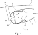
- the Fig. 5 shows a view C according to Fig. 6 and thus a view from the downstream side of the combustion chamber in a radial section plane.
- the recesses 30 are shown for the fuel nozzles 31.
- Both the inner combustion chamber wall 2 and the outer combustion chamber wall 3 are distributed around the circumference in the region of the mixing air holes 4 with bulges 6 which extend into the interior 5 of the combustion chamber and thus in the sectional view leads to a wave-shaped contour of the combustion chamber walls 2, 3 ,
- the Fig. 5 shows in simplified representation tools 35, which in conjunction with the FIGS. 9 and 10 be explained in more detail. These tools 35 serve to produce the bulges 6.
- the Fig. 5 shows two radially arranged cutting lines A and B. Sectional views along these section lines A and B are in the Fig. 6 and 7 shown.
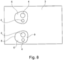
- the Fig. 6 shows a view along section line A and illustrates the shape and arrangement of the bulges 6. These point in the flow direction 7 (s. Fig. 4 ) an inflow surface 8 and an outflow surface 9. It can be seen that the inflow surface 8 is arranged at a shallower angle to the respective combustion chamber wall 2, 3, as the outflow surface 9. This is also again in the view of Fig. 8 clarified. It can be seen that the bulges 6 need not be circular. The geometry depends on the dimensioning and design of the combustion chamber. Also provided in the respective bulge 6 mixing air holes 4 may be provided with different diameters, analogous to the representation in Fig. 3 and the "counter swirl doublet mixer concept".
- the walls of the bulge 6 are provided with cooling air holes 25.
- a synopsis of Fig. 5 to 7 shows that alternately in the region of the mixed air holes, which are located in a central region of the cross section of the annular combustion chamber the inner combustion chamber wall 2 and the outer combustion chamber wall 3, to match the alternating arrangement of the mixed air holes (s. Fig. 3 ) the bulges 6 according to the invention are provided. These may be dimensioned differently on the inner combustion chamber wall 2 and on the outer combustion chamber wall 3. The height h and thus the penetration depth of the bulges are preferably selected so that the admixing air entering through the mixing air holes 4 is discharged in the same way as in the prior art (see FIG. Fig. 3 ), in which additional tubular air ducts 32 are provided.
- FIGS. 9 and 10 show, as already in Fig. 5 indicated, possibilities for producing the bulges 6 according to the invention.
- These can be pressed from the outside by suitable tools 35, which act similar to a thermoforming tool.
- suitable tools 35 which act similar to a thermoforming tool.
- the impressing from the outside tools can have a suitably selected shape to the contour of the bulges 6, which, for example, out Fig. 8 results in generating.
- the cooling air holes 25 are then formed, for example by laser drilling or the like, while the mixing air holes 4, for example by laser cutting, can be generated.
- the radii of the recesses are, for example, 10 to 15 mm in order not to impair the component strength and to allow production by the tools 35. These radii also determine the beginning and the end of the respective bulges both in the axial direction and in the circumferential direction.
- the bulge 6 is provided with an inflow surface 8 and an outflow surface 9.
- the mixing air holes 4 may be formed in the inflow surface 8, it is also possible to provide these at the apex of the respective bulge 6.
- the bulges 6 are, compared to the positions of the inner combustion chamber wall 2 and the outer combustion chamber wall 3, circumferentially offset from each other to supply mixing air according to the "counter swirl doublet mixer concept", as simplified in Fig. 3 is shown.
- the bulges 6 can be formed both symmetrically and asymmetrically, both in the axial direction and in the radial direction. This makes it possible to optimize the flow conditions in the interior 5 of the combustion chamber and to adapt the "counter swirl doublet mixer concept".
Landscapes
- Engineering & Computer Science (AREA)
- Chemical & Material Sciences (AREA)
- Combustion & Propulsion (AREA)
- Mechanical Engineering (AREA)
- General Engineering & Computer Science (AREA)
- Turbine Rotor Nozzle Sealing (AREA)
Claims (9)
- Chambre de combustion pour turbine à gaz, comprenant une paroi intérieure de chambre de combustion (2) et une paroi extérieure de chambre de combustion (3) qui forment une chambre de combustion annulaire, des trous d'air de mélange (4) étant réalisés de manière répartie sur la périphérie dans la paroi intérieure de chambre de combustion (2) et la paroi extérieure de chambre de combustion (3), la paroi de chambre de combustion respective (2, 3) étant bombée dans la région d'un trou d'air de mélange respectif (4) vers l'espace intérieur (5) de la chambre de combustion (15) et le trou d'air de mélange respectif (4) étant disposé dans le bombement (6),
caractérisée en ce que
le trou d'air de mélange respectif (4) disposé dans le bombement (6) est réalisé à chaque fois au niveau d'une surface d'afflux (8) du bombement (6), par rapport à la direction d'écoulement transversale (7) de la chambre de combustion (15). - Chambre de combustion pour turbine à gaz selon la revendication 1, caractérisée en ce que plusieurs bombements (6) sont réalisés de manière répartie sur la périphérie.
- Chambre de combustion pour turbine à gaz selon la revendication 1 ou 2, caractérisée en ce que les bombements (6) de la paroi intérieure de chambre de combustion (2) et de la paroi extérieure de chambre de combustion (3) sont disposés de manière décalée les uns par rapport aux autres.
- Chambre de combustion pour turbine à gaz selon l'une quelconque des revendications 1 à 3, caractérisée en ce qu'un trou d'air de mélange (4) ou plusieurs trous d'air de mélange (4) sont disposés dans un bombement (6).
- Chambre de combustion pour turbine à gaz selon l'une quelconque des revendications 1 à 4, caractérisée en ce que les bombements (6) présentent des surfaces latérales arrondies.
- Chambre de combustion pour turbine à gaz selon l'une quelconque des revendications 1 à 5, caractérisée en ce que les bombements (6), par rapport à la direction d'écoulement transversale (7) de la chambre de combustion (15), présentent une surface d'afflux (8) réalisée avec un plus petit angle par rapport à la paroi de chambre de combustion respective (2, 3) et une surface d'écoulement (9) réalisée avec un plus grand angle par rapport à celle-ci.
- Chambre de combustion pour turbine à gaz selon l'une quelconque des revendications 1 à 6, caractérisée en ce que les trous d'air de mélange (4) présentent des diamètres différents les uns par rapport aux autres.
- Chambre de combustion pour turbine à gaz selon l'une quelconque des revendications 1 à 7, caractérisée en ce qu'une hauteur (h) du bombement (6) est comprise entre 7,5 % et 25 % de la hauteur (H) de la chambre de combustion (15).
- Chambre de combustion pour turbine à gaz selon l'une quelconque des revendications 1 à 8, caractérisée en ce que la paroi du bombement (6) est pourvue de trous d'air de refroidissement (25) .
Applications Claiming Priority (2)
| Application Number | Priority Date | Filing Date | Title |
|---|---|---|---|
| DE102016201452.8A DE102016201452A1 (de) | 2016-02-01 | 2016-02-01 | Gasturbinenbrennkammer mit Wandkonturierung |
| PCT/EP2016/081220 WO2017133819A1 (fr) | 2016-02-01 | 2016-12-15 | Chambre de combustion pour turbine à gaz, délimitée par une paroi |
Publications (2)
| Publication Number | Publication Date |
|---|---|
| EP3245451A1 EP3245451A1 (fr) | 2017-11-22 |
| EP3245451B1 true EP3245451B1 (fr) | 2019-08-21 |
Family
ID=57714575
Family Applications (1)
| Application Number | Title | Priority Date | Filing Date |
|---|---|---|---|
| EP16822139.8A Active EP3245451B1 (fr) | 2016-02-01 | 2016-12-15 | Chambre de combustion pour turbine à gaz, délimitée par une paroi |
Country Status (4)
| Country | Link |
|---|---|
| US (1) | US10670270B2 (fr) |
| EP (1) | EP3245451B1 (fr) |
| DE (1) | DE102016201452A1 (fr) |
| WO (1) | WO2017133819A1 (fr) |
Families Citing this family (5)
| Publication number | Priority date | Publication date | Assignee | Title |
|---|---|---|---|---|
| US10337738B2 (en) * | 2016-06-22 | 2019-07-02 | General Electric Company | Combustor assembly for a turbine engine |
| US20200318549A1 (en) * | 2019-04-04 | 2020-10-08 | United Technologies Corporation | Non-axisymmetric combustor for improved durability |
| US11940151B2 (en) * | 2022-01-12 | 2024-03-26 | General Electric Company | Combustor with baffle |
| CN118548508B (zh) * | 2024-07-29 | 2024-09-27 | 中国空气动力研究与发展中心空天技术研究所 | 燃油喷孔出口面积连续可调的主燃级燃油喷嘴及调节方法 |
| US12553608B1 (en) * | 2025-01-08 | 2026-02-17 | Pratt & Whitney Canada Corp. | Additively manufactured combustor liner v-band cooling ring |
Family Cites Families (18)
| Publication number | Priority date | Publication date | Assignee | Title |
|---|---|---|---|---|
| FR1130169A (fr) | 1954-09-03 | 1957-01-31 | Rolls Royce | Perfectionnements à l'appareillage de combustion des moteurs à turbine à gaz |
| US3731484A (en) * | 1967-11-10 | 1973-05-08 | Lucas Ltd Joseph | Apparatus for regulation of airflow to flame tubes for gas turbine engines |
| GB1278590A (en) | 1968-09-20 | 1972-06-21 | Lucas Industries Ltd | Combustion chambers for gas turbine engines |
| FR2093115A5 (fr) | 1970-06-02 | 1972-01-28 | Snecma | |
| US3826082A (en) * | 1973-03-30 | 1974-07-30 | Gen Electric | Combustion liner cooling slot stabilizing dimple |
| DE2460740C3 (de) * | 1974-12-21 | 1980-09-18 | Mtu Motoren- Und Turbinen-Union Muenchen Gmbh, 8000 Muenchen | Brennkammer für Gasturbinentriebwerke |
| US3995422A (en) * | 1975-05-21 | 1976-12-07 | General Electric Company | Combustor liner structure |
| US4852355A (en) * | 1980-12-22 | 1989-08-01 | General Electric Company | Dispensing arrangement for pressurized air |
| FR2733582B1 (fr) * | 1995-04-26 | 1997-06-06 | Snecma | Chambre de combustion comportant une multiperforation d'inclinaison axiale et tangentielle variable |
| US7669422B2 (en) * | 2006-07-26 | 2010-03-02 | General Electric Company | Combustor liner and method of fabricating same |
| FR2922629B1 (fr) * | 2007-10-22 | 2009-12-25 | Snecma | Chambre de combustion a dilution optimisee et turbomachine en etant munie |
| US8966877B2 (en) | 2010-01-29 | 2015-03-03 | United Technologies Corporation | Gas turbine combustor with variable airflow |
| RU2519014C2 (ru) * | 2010-03-02 | 2014-06-10 | Дженерал Электрик Компани | Диффузор для камеры сгорания турбины (варианты) и камера сгорания турбины |
| DE102011076473A1 (de) * | 2011-05-25 | 2012-11-29 | Rolls-Royce Deutschland Ltd & Co Kg | Segmentbauteil aus Hochtemperaturgussmaterial für eine Ringbrennkammer, Ringbrennkammer für ein Flugzeugtriebwerk, Flugzeugtriebwerk und Verfahren zur Herstellung einer Ringbrennkammer |
| US20130091847A1 (en) * | 2011-10-13 | 2013-04-18 | General Electric Company | Combustor liner |
| US9423129B2 (en) * | 2013-03-15 | 2016-08-23 | Rolls-Royce Corporation | Shell and tiled liner arrangement for a combustor |
| WO2014149081A1 (fr) | 2013-03-15 | 2014-09-25 | Rolls-Royce Corporation | Chambre de combustion à doublet de contre-tourbillon |
| US10094564B2 (en) * | 2015-04-17 | 2018-10-09 | Pratt & Whitney Canada Corp. | Combustor dilution hole cooling system |
-
2016
- 2016-02-01 DE DE102016201452.8A patent/DE102016201452A1/de not_active Withdrawn
- 2016-12-15 US US15/577,679 patent/US10670270B2/en active Active
- 2016-12-15 EP EP16822139.8A patent/EP3245451B1/fr active Active
- 2016-12-15 WO PCT/EP2016/081220 patent/WO2017133819A1/fr not_active Ceased
Non-Patent Citations (1)
| Title |
|---|
| None * |
Also Published As
| Publication number | Publication date |
|---|---|
| US20180156459A1 (en) | 2018-06-07 |
| EP3245451A1 (fr) | 2017-11-22 |
| US10670270B2 (en) | 2020-06-02 |
| DE102016201452A1 (de) | 2017-08-03 |
| WO2017133819A1 (fr) | 2017-08-10 |
Similar Documents
| Publication | Publication Date | Title |
|---|---|---|
| EP2233836B1 (fr) | Générateur de torsion, procédé destiné à empêcher des retours de flammes dans un brûleur, doté d'au moins un générateur de torsion et d'un brûleur | |
| EP3087323B1 (fr) | Injecteur de combustible, brûleur avec un tel injecteur de combustible, et turbine à gaz munie dudit brûleur | |
| EP3245451B1 (fr) | Chambre de combustion pour turbine à gaz, délimitée par une paroi | |
| EP2179143B1 (fr) | Refroidissement de fente entre une paroi de chambre de combustion et une paroi de turbine d'une installation de turbine à gaz | |
| DE112017001792B4 (de) | Brennkammer und Verfahren zur Verbesserung der Brennkammerleistung | |
| DE102008022669A1 (de) | Brennstoffdüse und Verfahren für deren Herstellung | |
| CH698347A2 (de) | Brennstoffdüse mit integriertem Einlassströmungskonditionierer. | |
| EP2927594B1 (fr) | Chambre de combustion d'une turbine à gaz | |
| EP2085695A1 (fr) | Buse à combustible dotée d'un canal à tourbillon et procédé de fabrication d'une buse à combustible | |
| DE102014100085A1 (de) | Innenkühlkreise in Turbinenschaufeln | |
| EP2182285A1 (fr) | Pièce du brûleur pour une chambre de combustion d'une turbine à gaz et turbine à gaz | |
| DE112017002155B4 (de) | Gasturbine | |
| EP3182011A1 (fr) | Paroi d'un composant à refroidir à l'aide d'air de refroidissement, en particulier paroi de chambre de combustion de turbine à gaz | |
| DE102011050464A1 (de) | Vorrichtung und Filterungssysteme in Bezug auf Brennkammern in Verbrennungsturbinen | |
| DE102010037862A1 (de) | Wirbelkammern zur Spaltströmungssteuerung | |
| DE102011050491A1 (de) | Vorrichtung und Filterungssysteme in Bezug auf Brennkammern in Verbrennungsturbinen | |
| EP3064706A1 (fr) | Rangée d'aubes directrices pour une turbomachine traversée axialement | |
| EP2126321A1 (fr) | Turbine à gaz présentant une couronne directrice et un mélangeur | |
| DE102011055109A1 (de) | Anlage zum Lenken des Luftstroms in einer Kraftstoffdüsenanordnung | |
| WO2012113553A1 (fr) | Chambre de combustion de turbine à gaz | |
| WO2023180320A1 (fr) | Ensemble injecteur comprenant un tuyau de carburant central rendu étanche à un flux d'air entrant | |
| CH708705A2 (de) | Turbinenleitschaufelsegment mit Kühlung. | |
| EP3159487B1 (fr) | Stator d'une turbine à gaz ayant un guidage d'air de refroidissement amélioré | |
| EP3321589B1 (fr) | Buse de carburant d'une turbine à gaz dotée du générateur de tourbillons | |
| DE102016212649A1 (de) | Brennerdichtung einer Gasturbine und Verfahren zu deren Herstellung |
Legal Events
| Date | Code | Title | Description |
|---|---|---|---|
| STAA | Information on the status of an ep patent application or granted ep patent |
Free format text: STATUS: UNKNOWN |
|
| STAA | Information on the status of an ep patent application or granted ep patent |
Free format text: STATUS: THE INTERNATIONAL PUBLICATION HAS BEEN MADE |
|
| PUAI | Public reference made under article 153(3) epc to a published international application that has entered the european phase |
Free format text: ORIGINAL CODE: 0009012 |
|
| STAA | Information on the status of an ep patent application or granted ep patent |
Free format text: STATUS: REQUEST FOR EXAMINATION WAS MADE |
|
| 17P | Request for examination filed |
Effective date: 20170815 |
|
| AK | Designated contracting states |
Kind code of ref document: A1 Designated state(s): AL AT BE BG CH CY CZ DE DK EE ES FI FR GB GR HR HU IE IS IT LI LT LU LV MC MK MT NL NO PL PT RO RS SE SI SK SM TR |
|
| AX | Request for extension of the european patent |
Extension state: BA ME |
|
| STAA | Information on the status of an ep patent application or granted ep patent |
Free format text: STATUS: EXAMINATION IS IN PROGRESS |
|
| 17Q | First examination report despatched |
Effective date: 20180918 |
|
| GRAP | Despatch of communication of intention to grant a patent |
Free format text: ORIGINAL CODE: EPIDOSNIGR1 |
|
| STAA | Information on the status of an ep patent application or granted ep patent |
Free format text: STATUS: GRANT OF PATENT IS INTENDED |
|
| INTG | Intention to grant announced |
Effective date: 20190326 |
|
| DAV | Request for validation of the european patent (deleted) | ||
| DAX | Request for extension of the european patent (deleted) | ||
| GRAS | Grant fee paid |
Free format text: ORIGINAL CODE: EPIDOSNIGR3 |
|
| GRAA | (expected) grant |
Free format text: ORIGINAL CODE: 0009210 |
|
| STAA | Information on the status of an ep patent application or granted ep patent |
Free format text: STATUS: THE PATENT HAS BEEN GRANTED |
|
| RIN1 | Information on inventor provided before grant (corrected) |
Inventor name: DR. CLEMEN, CARSTEN |
|
| AK | Designated contracting states |
Kind code of ref document: B1 Designated state(s): AL AT BE BG CH CY CZ DE DK EE ES FI FR GB GR HR HU IE IS IT LI LT LU LV MC MK MT NL NO PL PT RO RS SE SI SK SM TR |
|
| REG | Reference to a national code |
Ref country code: GB Ref legal event code: FG4D Free format text: NOT ENGLISH |
|
| REG | Reference to a national code |
Ref country code: CH Ref legal event code: EP |
|
| REG | Reference to a national code |
Ref country code: DE Ref legal event code: R096 Ref document number: 502016006252 Country of ref document: DE |
|
| REG | Reference to a national code |
Ref country code: AT Ref legal event code: REF Ref document number: 1170191 Country of ref document: AT Kind code of ref document: T Effective date: 20190915 |
|
| REG | Reference to a national code |
Ref country code: IE Ref legal event code: FG4D Free format text: LANGUAGE OF EP DOCUMENT: GERMAN |
|
| REG | Reference to a national code |
Ref country code: LT Ref legal event code: MG4D |
|
| REG | Reference to a national code |
Ref country code: NL Ref legal event code: MP Effective date: 20190821 |
|
| PG25 | Lapsed in a contracting state [announced via postgrant information from national office to epo] |
Ref country code: PT Free format text: LAPSE BECAUSE OF FAILURE TO SUBMIT A TRANSLATION OF THE DESCRIPTION OR TO PAY THE FEE WITHIN THE PRESCRIBED TIME-LIMIT Effective date: 20191223 Ref country code: FI Free format text: LAPSE BECAUSE OF FAILURE TO SUBMIT A TRANSLATION OF THE DESCRIPTION OR TO PAY THE FEE WITHIN THE PRESCRIBED TIME-LIMIT Effective date: 20190821 Ref country code: SE Free format text: LAPSE BECAUSE OF FAILURE TO SUBMIT A TRANSLATION OF THE DESCRIPTION OR TO PAY THE FEE WITHIN THE PRESCRIBED TIME-LIMIT Effective date: 20190821 Ref country code: LT Free format text: LAPSE BECAUSE OF FAILURE TO SUBMIT A TRANSLATION OF THE DESCRIPTION OR TO PAY THE FEE WITHIN THE PRESCRIBED TIME-LIMIT Effective date: 20190821 Ref country code: HR Free format text: LAPSE BECAUSE OF FAILURE TO SUBMIT A TRANSLATION OF THE DESCRIPTION OR TO PAY THE FEE WITHIN THE PRESCRIBED TIME-LIMIT Effective date: 20190821 Ref country code: NO Free format text: LAPSE BECAUSE OF FAILURE TO SUBMIT A TRANSLATION OF THE DESCRIPTION OR TO PAY THE FEE WITHIN THE PRESCRIBED TIME-LIMIT Effective date: 20191121 Ref country code: NL Free format text: LAPSE BECAUSE OF FAILURE TO SUBMIT A TRANSLATION OF THE DESCRIPTION OR TO PAY THE FEE WITHIN THE PRESCRIBED TIME-LIMIT Effective date: 20190821 Ref country code: BG Free format text: LAPSE BECAUSE OF FAILURE TO SUBMIT A TRANSLATION OF THE DESCRIPTION OR TO PAY THE FEE WITHIN THE PRESCRIBED TIME-LIMIT Effective date: 20191121 |
|
| PG25 | Lapsed in a contracting state [announced via postgrant information from national office to epo] |
Ref country code: AL Free format text: LAPSE BECAUSE OF FAILURE TO SUBMIT A TRANSLATION OF THE DESCRIPTION OR TO PAY THE FEE WITHIN THE PRESCRIBED TIME-LIMIT Effective date: 20190821 Ref country code: ES Free format text: LAPSE BECAUSE OF FAILURE TO SUBMIT A TRANSLATION OF THE DESCRIPTION OR TO PAY THE FEE WITHIN THE PRESCRIBED TIME-LIMIT Effective date: 20190821 Ref country code: LV Free format text: LAPSE BECAUSE OF FAILURE TO SUBMIT A TRANSLATION OF THE DESCRIPTION OR TO PAY THE FEE WITHIN THE PRESCRIBED TIME-LIMIT Effective date: 20190821 Ref country code: RS Free format text: LAPSE BECAUSE OF FAILURE TO SUBMIT A TRANSLATION OF THE DESCRIPTION OR TO PAY THE FEE WITHIN THE PRESCRIBED TIME-LIMIT Effective date: 20190821 Ref country code: GR Free format text: LAPSE BECAUSE OF FAILURE TO SUBMIT A TRANSLATION OF THE DESCRIPTION OR TO PAY THE FEE WITHIN THE PRESCRIBED TIME-LIMIT Effective date: 20191122 Ref country code: IS Free format text: LAPSE BECAUSE OF FAILURE TO SUBMIT A TRANSLATION OF THE DESCRIPTION OR TO PAY THE FEE WITHIN THE PRESCRIBED TIME-LIMIT Effective date: 20191221 |
|
| PG25 | Lapsed in a contracting state [announced via postgrant information from national office to epo] |
Ref country code: TR Free format text: LAPSE BECAUSE OF FAILURE TO SUBMIT A TRANSLATION OF THE DESCRIPTION OR TO PAY THE FEE WITHIN THE PRESCRIBED TIME-LIMIT Effective date: 20190821 |
|
| PG25 | Lapsed in a contracting state [announced via postgrant information from national office to epo] |
Ref country code: RO Free format text: LAPSE BECAUSE OF FAILURE TO SUBMIT A TRANSLATION OF THE DESCRIPTION OR TO PAY THE FEE WITHIN THE PRESCRIBED TIME-LIMIT Effective date: 20190821 Ref country code: IT Free format text: LAPSE BECAUSE OF FAILURE TO SUBMIT A TRANSLATION OF THE DESCRIPTION OR TO PAY THE FEE WITHIN THE PRESCRIBED TIME-LIMIT Effective date: 20190821 Ref country code: PL Free format text: LAPSE BECAUSE OF FAILURE TO SUBMIT A TRANSLATION OF THE DESCRIPTION OR TO PAY THE FEE WITHIN THE PRESCRIBED TIME-LIMIT Effective date: 20190821 Ref country code: DK Free format text: LAPSE BECAUSE OF FAILURE TO SUBMIT A TRANSLATION OF THE DESCRIPTION OR TO PAY THE FEE WITHIN THE PRESCRIBED TIME-LIMIT Effective date: 20190821 Ref country code: EE Free format text: LAPSE BECAUSE OF FAILURE TO SUBMIT A TRANSLATION OF THE DESCRIPTION OR TO PAY THE FEE WITHIN THE PRESCRIBED TIME-LIMIT Effective date: 20190821 |
|
| PG25 | Lapsed in a contracting state [announced via postgrant information from national office to epo] |
Ref country code: CZ Free format text: LAPSE BECAUSE OF FAILURE TO SUBMIT A TRANSLATION OF THE DESCRIPTION OR TO PAY THE FEE WITHIN THE PRESCRIBED TIME-LIMIT Effective date: 20190821 Ref country code: SM Free format text: LAPSE BECAUSE OF FAILURE TO SUBMIT A TRANSLATION OF THE DESCRIPTION OR TO PAY THE FEE WITHIN THE PRESCRIBED TIME-LIMIT Effective date: 20190821 Ref country code: SK Free format text: LAPSE BECAUSE OF FAILURE TO SUBMIT A TRANSLATION OF THE DESCRIPTION OR TO PAY THE FEE WITHIN THE PRESCRIBED TIME-LIMIT Effective date: 20190821 Ref country code: IS Free format text: LAPSE BECAUSE OF FAILURE TO SUBMIT A TRANSLATION OF THE DESCRIPTION OR TO PAY THE FEE WITHIN THE PRESCRIBED TIME-LIMIT Effective date: 20200224 |
|
| REG | Reference to a national code |
Ref country code: DE Ref legal event code: R097 Ref document number: 502016006252 Country of ref document: DE |
|
| PLBE | No opposition filed within time limit |
Free format text: ORIGINAL CODE: 0009261 |
|
| STAA | Information on the status of an ep patent application or granted ep patent |
Free format text: STATUS: NO OPPOSITION FILED WITHIN TIME LIMIT |
|
| PG2D | Information on lapse in contracting state deleted |
Ref country code: IS |
|
| REG | Reference to a national code |
Ref country code: CH Ref legal event code: PL |
|
| 26N | No opposition filed |
Effective date: 20200603 |
|
| REG | Reference to a national code |
Ref country code: BE Ref legal event code: MM Effective date: 20191231 |
|
| PG25 | Lapsed in a contracting state [announced via postgrant information from national office to epo] |
Ref country code: MC Free format text: LAPSE BECAUSE OF FAILURE TO SUBMIT A TRANSLATION OF THE DESCRIPTION OR TO PAY THE FEE WITHIN THE PRESCRIBED TIME-LIMIT Effective date: 20190821 Ref country code: SI Free format text: LAPSE BECAUSE OF FAILURE TO SUBMIT A TRANSLATION OF THE DESCRIPTION OR TO PAY THE FEE WITHIN THE PRESCRIBED TIME-LIMIT Effective date: 20190821 |
|
| PG25 | Lapsed in a contracting state [announced via postgrant information from national office to epo] |
Ref country code: IE Free format text: LAPSE BECAUSE OF NON-PAYMENT OF DUE FEES Effective date: 20191215 Ref country code: LU Free format text: LAPSE BECAUSE OF NON-PAYMENT OF DUE FEES Effective date: 20191215 |
|
| PG25 | Lapsed in a contracting state [announced via postgrant information from national office to epo] |
Ref country code: CH Free format text: LAPSE BECAUSE OF NON-PAYMENT OF DUE FEES Effective date: 20191231 Ref country code: BE Free format text: LAPSE BECAUSE OF NON-PAYMENT OF DUE FEES Effective date: 20191231 Ref country code: LI Free format text: LAPSE BECAUSE OF NON-PAYMENT OF DUE FEES Effective date: 20191231 |
|
| PG25 | Lapsed in a contracting state [announced via postgrant information from national office to epo] |
Ref country code: CY Free format text: LAPSE BECAUSE OF FAILURE TO SUBMIT A TRANSLATION OF THE DESCRIPTION OR TO PAY THE FEE WITHIN THE PRESCRIBED TIME-LIMIT Effective date: 20190821 |
|
| PG25 | Lapsed in a contracting state [announced via postgrant information from national office to epo] |
Ref country code: HU Free format text: LAPSE BECAUSE OF FAILURE TO SUBMIT A TRANSLATION OF THE DESCRIPTION OR TO PAY THE FEE WITHIN THE PRESCRIBED TIME-LIMIT; INVALID AB INITIO Effective date: 20161215 Ref country code: MT Free format text: LAPSE BECAUSE OF FAILURE TO SUBMIT A TRANSLATION OF THE DESCRIPTION OR TO PAY THE FEE WITHIN THE PRESCRIBED TIME-LIMIT Effective date: 20190821 |
|
| GBPC | Gb: european patent ceased through non-payment of renewal fee |
Effective date: 20201215 |
|
| PG25 | Lapsed in a contracting state [announced via postgrant information from national office to epo] |
Ref country code: GB Free format text: LAPSE BECAUSE OF NON-PAYMENT OF DUE FEES Effective date: 20201215 |
|
| PG25 | Lapsed in a contracting state [announced via postgrant information from national office to epo] |
Ref country code: MK Free format text: LAPSE BECAUSE OF FAILURE TO SUBMIT A TRANSLATION OF THE DESCRIPTION OR TO PAY THE FEE WITHIN THE PRESCRIBED TIME-LIMIT Effective date: 20190821 |
|
| REG | Reference to a national code |
Ref country code: AT Ref legal event code: MM01 Ref document number: 1170191 Country of ref document: AT Kind code of ref document: T Effective date: 20211215 |
|
| PG25 | Lapsed in a contracting state [announced via postgrant information from national office to epo] |
Ref country code: AT Free format text: LAPSE BECAUSE OF NON-PAYMENT OF DUE FEES Effective date: 20211215 |
|
| P01 | Opt-out of the competence of the unified patent court (upc) registered |
Effective date: 20230528 |
|
| PGFP | Annual fee paid to national office [announced via postgrant information from national office to epo] |
Ref country code: FR Payment date: 20251230 Year of fee payment: 10 |
|
| PGFP | Annual fee paid to national office [announced via postgrant information from national office to epo] |
Ref country code: DE Payment date: 20251229 Year of fee payment: 10 |