EP3249975A1 - Base station apparatus, user apparatus, and method used in mobile communications system - Google Patents
Base station apparatus, user apparatus, and method used in mobile communications system Download PDFInfo
- Publication number
- EP3249975A1 EP3249975A1 EP17179267.4A EP17179267A EP3249975A1 EP 3249975 A1 EP3249975 A1 EP 3249975A1 EP 17179267 A EP17179267 A EP 17179267A EP 3249975 A1 EP3249975 A1 EP 3249975A1
- Authority
- EP
- European Patent Office
- Prior art keywords
- control signal
- bandwidth
- areas
- imt
- downlink control
- Prior art date
- Legal status (The legal status is an assumption and is not a legal conclusion. Google has not performed a legal analysis and makes no representation as to the accuracy of the status listed.)
- Withdrawn
Links
Images



Classifications
-
- H—ELECTRICITY
- H04—ELECTRIC COMMUNICATION TECHNIQUE
- H04W—WIRELESS COMMUNICATION NETWORKS
- H04W48/00—Access restriction; Network selection; Access point selection
- H04W48/08—Access restriction or access information delivery, e.g. discovery data delivery
- H04W48/10—Access restriction or access information delivery, e.g. discovery data delivery using broadcasted information
-
- H—ELECTRICITY
- H04—ELECTRIC COMMUNICATION TECHNIQUE
- H04W—WIRELESS COMMUNICATION NETWORKS
- H04W72/00—Local resource management
- H04W72/12—Wireless traffic scheduling
- H04W72/1215—Wireless traffic scheduling for collaboration of different radio technologies
-
- H—ELECTRICITY
- H04—ELECTRIC COMMUNICATION TECHNIQUE
- H04W—WIRELESS COMMUNICATION NETWORKS
- H04W48/00—Access restriction; Network selection; Access point selection
- H04W48/08—Access restriction or access information delivery, e.g. discovery data delivery
-
- H—ELECTRICITY
- H04—ELECTRIC COMMUNICATION TECHNIQUE
- H04W—WIRELESS COMMUNICATION NETWORKS
- H04W72/00—Local resource management
- H04W72/20—Control channels or signalling for resource management
- H04W72/23—Control channels or signalling for resource management in the downlink direction of a wireless link, i.e. towards a terminal
-
- H—ELECTRICITY
- H04—ELECTRIC COMMUNICATION TECHNIQUE
- H04W—WIRELESS COMMUNICATION NETWORKS
- H04W72/00—Local resource management
- H04W72/50—Allocation or scheduling criteria for wireless resources
- H04W72/53—Allocation or scheduling criteria for wireless resources based on regulatory allocation policies
-
- H—ELECTRICITY
- H04—ELECTRIC COMMUNICATION TECHNIQUE
- H04W—WIRELESS COMMUNICATION NETWORKS
- H04W88/00—Devices specially adapted for wireless communication networks, e.g. terminals, base stations or access point devices
- H04W88/02—Terminal devices
-
- H—ELECTRICITY
- H04—ELECTRIC COMMUNICATION TECHNIQUE
- H04W—WIRELESS COMMUNICATION NETWORKS
- H04W88/00—Devices specially adapted for wireless communication networks, e.g. terminals, base stations or access point devices
- H04W88/08—Access point devices
- H04W88/10—Access point devices adapted for operation in multiple networks, e.g. multi-mode access points
Definitions
- the present invention relates to the technical field of mobile communications and particularly relates to mobile communications systems, base station apparatuses, user apparatuses, and methods.
- a representative example of a mobile communications system to succeed the Third Generation (3G) is a Long Term Evolution (LTE) system, which is also called an E-UTRA (Evolved Universal Terrestrial Radio Access) system.
- LTE Long Term Evolution
- E-UTRA Evolved Universal Terrestrial Radio Access
- the Third Generation system can use a fixed bandwidth of 5 MHz to achieve a transmission rate in the order of up to 2 Mbps in downlink.
- a variable bandwidth of 1.4 MHz to 20 MHz may be used to achieve a transmission rate in the order of up to 300 Mbps in downlink and approximately 75 Mbps in uplink.
- IMT-Advanced an LTE-Advanced system
- 4G Fourth Generation
- FIG. 1 schematically illustrates how the 3G system, the LTE system, and the IMT-A system co-exist in the same region.
- Non-patent document 1 3GPP, TR25.912 (V7.1.0), "Feasibility study for Evolved UTRA and UTRAN, Sept. 2006
- the problem to be solved by the present invention is to efficiently transmit a control signal for each system while maintaining backward compatibility when multiple old and new mobile communications systems co-exist.
- a base station apparatus which is used in a region in which at least a first system and a second system co-exist. Mobile communication is conducted in the first system using a variable system bandwidth not more than a basic bandwidth. Mobile communication is conducted in the second system using a variable system bandwidth which is no more than a bandwidth of an advanced system band which is at least as wide as multiple of the basic bandwidths.
- the base station apparatus includes a first generating unit which generates a control signal for the first system; a second generating unit which generates a control signal for the second system; a multiplexing unit which orthogonally multiplexes control signals from the first generating unit and the second generating unit; and a transmitting unit which transmits a downlink signal including a control signal after the orthogonal multiplexing.
- the advanced system band is divided such that it includes multiple areas of the basic bandwidth.
- the control signal for the first system is arranged to be included in one area.
- the control signal for the second system is arranged to be included in at least one area.
- the control signal for the second system may be included in multiple areas and channel encoded for each of the areas.
- the control signal for the second system may be included in multiple areas, and a unit for channel coding the control signal may be all of the multiple areas.
- the control signal for the second system may be arranged to be included within one area.
- An area in which the control signal for the second system is included may be set for each user.
- the control signal after the orthogonal multiplexing and a data signal including user traffic data may be orthogonally multiplexed using at least a time division multiplexing scheme.
- the present invention is desirable in efficiently transmitting a control signal for each system while maintaining backward compatibility when multiple old and new mobile communications systems co-exist.
- an example is described of a case such that an LTE system and an IMT-A system co-exist.
- the present invention is not limited to a combination of the LTE system and the IMT-A system, so that the present invention may be applied to any combination of various appropriate systems.
- At least one physical channel is shared by multiple mobile stations (user apparatuses) to conduct mobile communication.
- OFDMA orthogonal frequency division multiple access
- SC-FDMA single carrier-frequency division multiple access
- the SC-FDMA scheme is also called a DFT spread (discrete Fourier transformation spread) OFDM scheme.
- PUSCH physical uplink shared channel
- PDSCH physical downlink shared channel
- a control channel used in the signaling is called a physical downlink control channel (PDCCH).
- the PDCCH is called a downlink L1/L2 control channel, a DL-L1/L2 control channel, or downlink control information (DCI).
- DCI downlink control information
- the PDCCH information includes a downlink/uplink (DL/UL) scheduling grant and a transmission power control (TPC) bit, for example.
- the PDCCH is mapped to one to three OFDM symbols from the beginning, out of 14 OFDM symbols, for example, within one sub-frame. How many OFDM symbols from the beginning the PDCCH is mapped to is specified by a below-described PCFICH, and is reported to a mobile station.
- PCFICH PCFICH
- a physical control format indicator channel (PCFICH) and a physical HARQ indicator channel (PHICH: a physical hybrid ARQ indicator channel) are also transmitted.
- PCFICH physical control format indicator channel
- PHICH physical HARQ indicator channel
- the PCFICH is a signal for reporting, to a mobile station, the number of OFDM symbols including the PDCCH.
- the PCFICH may be called a downlink (DL) L1/L2 control format indicator.
- the PHICH is a channel which transmits transmission acknowledgment information on the physical uplink shared channel (PUSCH).
- the transmission acknowledgement information includes ACK (acknowledgement), which is a positive response, and NACK (negative acknowledgement), which is a negative response.
- FIG. 2 shows an example of a downlink sub-frame configuration.
- one sub-frame is 1 ms, for example, within which one sub-frame there are 14 OFDM symbols.
- the sub-frame is also called a transmission time interval (TTI).
- TTI transmission time interval
- a number in a time axis direction (#1, #2,..., #14) shows a number which identifies an OFDM symbol
- a number in a frequency axis direction #1, #2,..., #L-1, #L; L is a positive integer
- a physical downlink control channel (PDCCH), etc. is mapped to M OFDM symbols at the beginning of the sub-frame.
- a value of M may be set in three ways: 1, 2, or 3.
- user data includes a control signals, etc., for processes of radio resource control (RRC), an IP packet such as a voice packet (VoIP), file transfer (FTP), web browsing, etc.
- RRC radio resource control
- IP IP packet
- FTP file transfer
- L resource blocks are provided in a system bandwidth.
- a frequency bandwidth per resource block is 180 kHz, for example; 12 sub-carriers exist within one resource block, for example.
- a total number L of resource blocks may be 25 when the system bandwidth is 5 MHz, 50 when the system bandwidth is 10 MHz, 100 when the system bandwidth is 20 MHz, etc.
- a system bandwidth of a size which differs from region to region or from cell to cell may be used.
- the user apparatus may conduct mobile communications using a shared channel within a range of the system bandwidth in the region or the cell.
- FIG. 4 illustrates an example of an uplink sub-frame configuration in the LTE system.
- FIG. 4 shows a resource (multiple resource blocks) for transmitting a physical uplink shared channel (PUSCH), and a resource (a dedicated bandwidth for an uplink control signal) for a user to which such a resource is not allocated to transmit an uplink control signal.
- the latter is called a physical uplink control signal (PUCCH: physical uplink control channel).
- PUCCH physical uplink control channel
- at least one of the four resource blocks is allocated to a user, first and second hopping control signals are provided in sub-frames or transmission time intervals (TTIs), and third and fourth hopping control signals are provided in a subsequent sub-frame.
- TTIs transmission time intervals
- third and fourth hopping control signals are provided in a subsequent sub-frame.
- Each of the hopping control signals corresponds to the PUCCH.
- Hopping can be conducted on time and frequency in a TTI or sub-frame to obtain a diversity effect.
- Each of the first to fourth hopping control signals may be occupied by one user, or it may be multiplexed for multiple users.
- the size of the system bandwidth is provided at the same level as the downlink. In the LTE system, a system bandwidth is provided which is variable between uplink and downlink.
- FIG. 5 shows how a control signal is transmitted in downlink according to one embodiment of the present invention.
- an 80 MHz system bandwidth is provided for an IMT-A system, so that mobile communication is conducted in a variable system bandwidth which is not more than 80 MHz.
- the system bandwidth may vary from region to region or from cell to cell. It is not mandatory for all the users to be able to communicate in 80 MHz, so that there may be a user which can only communicate in a bandwidth such as 40 MHz, for example.
- a maximum system bandwidth provided in the IMT-A system is to be called an advanced systems bandwidth (the bandwidth is an advanced system bandwidth).
- the advanced system bandwidth is divided into areas of a standard bandwidth, which, in the illustrated example, is 20MHz. While not mandatory, this 20 MHz corresponds to a maximum bandwidth in an LTE system.
- a control signal is mapped to first one to three OFDM symbols.
- a control signal is mapped to a first one to three OFDM symbols.
- a control signal is mapped to three OFDM symbols.
- the first user UE1 (E-UTRA) is subscribing to the LTE system, it is not subscribing to the IMT-A system.
- the areas are named P, Q, R, and 5 from the left, all control signals intended for the user are mapped to a bandwidth of the area Q, which is the second from the left.
- the control signal includes uplink and downlink scheduling information, transmission power control information, etc.
- a control signal for the LTE system and a control signal for the IMT-A system are orthogonally multiplexed in units of resource elements by a Frequency Division Multiplexing scheme (FDM) and a Time Division Multiplexing scheme (TDM) (control channels within the IMT-Advanced system may be code multiplexed.)
- FDM Frequency Division Multiplexing scheme
- TDM Time Division Multiplexing scheme
- One resource element represents a resource of a unit specified by one sub-carrier and one OFDM symbol.
- a control signal intended for a user of the LTE system is only mapped into the area, which is the second from the left. Therefore, this user may decode only a 20 MHz bandwidth, which is the second from the left, to take out a control signal intended for an own device.
- a downlink control signal for the LTE system is channel coded such that it falls within the 20 MHz bandwidth.
- the control signal may be mapped such that it falls within the 20 MHz area for the LTE system.
- the second user UE2 (IMT-A) is subscribing to the IMT-A system.
- the control signal intended for the user is mapped to the entire Advanced system bandwidth (mapped to all four areas).
- transmission power control information, scheduling information, etc., for uplink and downlink may be included in the control information.
- each user shares a physical channel, and at least one resource block within a system bandwidth is used to conduct mobile communications.
- the third user UE3 (IMT-A) is also subscribing to the IMT-A system.
- the control signal intended for the user is mapped not to the entire Advanced system bandwidth but a portion thereof (mapped to two areas or 40 MHz).
- the control signal intended for the third user UE3 (IMT-A) and the control signal intended for the first and the second users UE1, UE2 are channel coded separately.
- the control signal intended for the LTE system user is channel coded within a 20 MHz allowed for the LTE system. Moreover, the control signals intended for the first, second, and third users are channel coded separately. Therefore, the first user UE1 (E-UTRA) properly decodes a control signal intended for an own device regardless of whether a control signal for the second or third user is present (in other words, whether another control signal is present does not have to be taken into account.) Conversely, the second and the third users UE2, UE3 (IMT-A) may also properly decode a control signal intended for an own device regardless of whether a control signal for the first user is present. In this way, both new and old users may properly take out a control signal intended for the own device regardless of whether a control signal for the other system is present.
- the control signal intended for the user (1) may be channel coded for each area of a standard bandwidth (20 MHz), or (2) may be channel coded collectively in all of the multiple areas.
- the lower left side of FIG. 5 shows how a control signal intended for UE2 (IMT-A) is mapped across four areas P, Q, R, and S, and how it is channel coded for each area.
- a control signal intended for UE3 (IMT-A) is mapped to the areas R and S.
- a control signal intended for UE1 (E-UTRA) belonging to an LTE system is mapped such that it falls within an area.
- control signal intended for UE1 (E-UTRA) is mapped within 20MHz of area Q. Therefore, channel coding the control signal again for the IMT-A system for each area for mapping is preferable from a point of view of increasing commonality with the LTE system.
- the UE2 can use an appropriate resource within all of the four areas (80 MHz).
- resource allocation information scheduling information
- scheduling information for 20 MHz in the area P is mapped into the area P.
- scheduling information for the bandwidths in the areas Q, R, and S is mapped into the respective areas Q, R, and S.
- FIG. 5 shows how a control signal intended for UE2 (IMT-A) is channel coded, not for each area, but for all of the four areas.
- a control signal intended for UE2 IMT-A
- both of the two areas R and S are channel encoded.
- a control signal intended for UE1 (E-UTRA) belonging to the LTE system is mapped such that it falls within one area Q.
- a unit for channel coding differs between the IMT-A system and the LTE system.
- control signal for the IMT-A system it is preferable from the point of view of increasing the error correcting capabilities to lengthen one unit of channel coding (coding gain increases.) Moreover, information within a control signal can be mapped to anywhere within multiple areas, so that this method is preferable also from a point of view of being able to expect a frequency diversity effect.
- FIG. 6 shows an example of a different way of mapping a control signal.
- the control signal for the IMT-A system is mapped to multiple areas P, Q, R, and S according to the bandwidth usable by the user.
- the data signal is communicated in 80 MHz, for example, it is not necessarily the case that the control signal is also transmitted in 80 MHz.
- a control signal for one user is only mapped to one area. The corresponding relationship between the user and the area is determined appropriately.
- a control signal intended for the first user UE1 is mapped to the area Q.
- the control signal for the second user UE 2 is mapped to the area P.
- the control signal for the third user UE 3 is mapped to the area R.
- a control signal intended for a different user (not shown; a user subscribing to the IMT-A system) is mapped to the area S.
- a control signal intended for any user is mapped only into one area, this example is preferable from a point of view of maintaining commonality, etc.
- the standard bandwidth is 20 MHz, but a different bandwidth may be used.
- the standard bandwidth may be 15 MHz.
- the standard bandwidth may take any value, but preferably corresponds to any variable system bandwidth of the LTE system. More specifically, the standard bandwidth preferably corresponds to any one of 1. 4 MHz, 3 MHz, 5MHz, 10 MHz, 15MHz, and 20 MHz. Moreover, neither end of the Advanced system bandwidth has to be aligned with the border of the breakdown by the standard bandwidth.
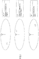
- FIG. 7 shows, within an 80 MHz Advanced system bandwidth of the IMT-A system, a case such that three 20 MHz areas are included and a case such that four 15 MHz areas are included. In either case, neither end of the Advanced system bandwidth is aligned with the area of the standard bandwidth. Also in this case, any of the areas of the standard bandwidth is allocated to the LTE system. In this way, there may be various cases with respect to the mutual relationships among the area of the standard bandwidth, bandwidth of the LTE system, and the Advanced system bandwidth.
- FIG. 8 shows how a control signal is transmitted in uplink according to one embodiment of the present invention.
- a 40 MHz system bandwidth is provided for an uplink IMT-A system, so that mobile communication is conducted in a variable system bandwidth which is not more than 40 MHz.
- the system bandwidth may vary from region to region or from cell to cell. It is not mandatory for all the users to be able to communicate in 40 MHz, so that there may be a user which can only communicate in a bandwidth such as 20 MHz, for example.
- a maximum system bandwidth provided in the IMT-A system is to be called an Advanced system band (the bandwidth thereof is an Advanced system bandwidth).
- the Advanced system bandwidth is divided into areas of a standard bandwidth, which, in the illustrated example, is 20 MHz. The two areas are specified as V and W for convenience. While not mandatory, this 20 MHz corresponds to the maximum bandwidth in the LTE system.
- the 80 MHz Advanced system bandwidth may also be provided for uplink.
- higher speed and larger capacity are in strong demand in downlink, there may be numerous situations such that higher speed in uplink is not in such strong demand.
- only 40 MHz is provided for uplink.
- a resource dedicated for the control signal is provided for both ends of the 20 MHz system bandwidth (See FIG. 4 ). Also in the present example, a resource dedicated for the control signal is provided at both ends of the 20 MHz standard bandwidth.
- the resource is provided from a point of view that a user of the LTE system can transmit an uplink control signal (PUCCH) regardless of whether the IMT-A system is present. Assuming the signal for the LTE system is transmitted in the area V, a resource for the control signal (PUCCH) is provided at least at both ends within the area V.
- an uplink signal in the LTE system is transmitted by a single-carrier scheme. In order to obtain a signal quality improvement effect through a frequency diversity effect while using a single-carrier scheme, the uplink control signal is transmitted while undergoing frequency hopping in between both ends of the standard bandwidth.
- the uplink control signal (PUCCH) from the first user UE1 is transmitted while undergoing frequency hopping in a dedicated bandwidth at both ends of the area V.
- the second user UE2 (IMT-A) is subscribing to the IMT-A system, making it possible to transmit in 40 MHz bandwidth.
- the uplink control signal of this user is transmitted using a resource provided for not only the area V but also the area W. Also in the area V, in a manner similar to the area W, a resource dedicated to the control signal is provided at both ends of the area.
- the uplink control signal may include any appropriate information. While not mandatory, a resource is not allocated to an uplink shared channel as in a case of the LTE system, so this resource may be used when reporting some information to the base station. For example, this resource may be used for reporting CQI to the base station periodically and/or for speedily reporting acknowledgement information (ACK/NACK) to a downlink data signal.
- ACK/NACK speedily reporting acknowledgement information
- the uplink control signal for the UE2 it is not mandatory for the uplink control signal for the UE2 to use all resources provided in the areas V and W. For example, only the left side of the area V and the right side of the area W may be used. Based on the control information amount and/or required frequency diversity effect, an appropriate amount of resources may be determined.
- a single-carrier scheme is adopted for uplink
- a multi-carrier scheme is allowed for uplink.
- a more appropriate one of the single--carrier scheme and the multi-carrier scheme is selectively used for uplink.
- a single-, or multi-carrier scheme may be used for uplink in a fixed manner.
- the uplink control signals may be transmitted simultaneously using a different frequency.
- the third user UE3 (IMT-A) is also subscribing to the IMT-A system, it may transmit in uplink only in 20 MHz bandwidth.
- the uplink control signal for this user may be transmitted using the area V or W, but, in the example shown, is transmitted using only the area W.
- uplink control signals are simultaneously transmitted within the area W in different frequencies.
- the control signals for the first, the second, and the third user are orthogonally multiplexed using an appropriate orthogonal multiplexing scheme.
- orthogonalization between the first user and the second user is performed using the code multiplexing scheme.
- Orthogonalization between the first user and the third user is performed using the frequency multiplexing scheme.
- Orthogonalization between the second user and the third user is performed using the code multiplexing scheme.
- the channel coding of the control signal may be conducted for each area, or for all of the multiple areas. It is preferable from the point of view of increasing commonality between the LTE system and the IMT-A system to channel code for each area of the standard bandwidth. It is preferable from the point of view of improving the coding gain or the frequency diversity effect to provide for a collection of control signals across multiple areas to be channel coded.
- FIG. 9 shows how the uplink control signals from the UEs are transmitted in a single-carrier scheme. This may be advantageous when the amount of control information transmitted in uplink is small, for example.
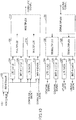
- FIG. 10 illustrates a partial functional diagram of a base station apparatus.
- FIG. 10 shows, for downlink, a scheduler 102, a control signal generator 104 and a data signal generator 110 for the LTE system, a control signal generator 106 and a data signal generator 112 for the ITM-A system, and multiplexers 108, 114, and 116.
- FIG. 10 shows, for uplink, demultiplexers 120, 122, 128, a control signal demodulator 124 and a data signal demodulator 130 for the LTE system, and a control signal demodulator 126 and a data signal demodulator 132 for the IMT-A system.
- the scheduler 102 prepares an allocation plan of (schedules) a radio resource in downlink and uplink.
- the scheduling may use any appropriate amount as a basis, or may be done based on any appropriate decision criteria and/or algorithm.
- scheduling may be done based on CQI reported from the user apparatus.
- scheduling may be done based on a received quality of a pilot signal received by the base station.
- Scheduling may be done according to a proportional fairness scheme, for example.
- scheduling is conducted not only for the 20 MHz-wide bandwidth for the LTE system, but also for the 80 MHz-bandwidth for the IMT-A system including the same.
- scheduling is conducted not only for the 20 MHz-wide bandwidth for the LTE system, but also for the 40 MHz-bandwidth for the IMT-A system including the same. Scheduling is conducted, also taking into account adaptive modulation and channel coding schemes.
- the LTE system is operating in an area of a specific standard bandwidth (20 MHz).
- the LTE system is operating in area Q for downlink and in area R for uplink. Therefore, scheduling information on the bandwidth of the area Q for downlink is provided to the control signal generator 104, while other scheduling information in downlink is provided to the control signal generator 106.
- scheduling information on the bandwidth of the area R for uplink is provided to the control signal generator 104, while other scheduling information in uplink is provided to the control signal generator 106.
- the control signal generator 104 for the LTE system generates a downlink control signal for the LTE system.
- the control signal generator 104 performs processes of channel coding, data modulation, interleaving, etc. to generate a downlink control signal.
- the downlink control signal is typically a PDCCH channel or an L1/L2 control channel.
- the downlink control channel is channel coded for each user, and mapped to a bandwidth within the area Q.
- the downlink control signal may be called a lower-layer control signal.
- This downlink control signal typically includes scheduling information, but may include other control information such as transmission power control information, etc.
- the data signal generator 110 for the LTE system generates a downlink data signal for the LTE system.
- the data signal generator 110 performs processes of channel coding, data modulation, interleaving, etc., to generate a downlink data signal.
- This downlink data signal is called a PDSCH.
- the PDSCH may include user traffic data, broadcast information, upper layer control information, etc.
- the control signal generator 106 for the IMT-A system generates a downlink control signal for the IMT-A system.
- the control signal generator 106 performs processes of channel coding, data modulation, interleaving, etc., to generate a downlink control signal.
- the control signal for the second user UE2, the control signal for the third user UE3, etc., that are described in FIG. 5 apply to this downlink control signal.
- This downlink control signal also typically includes scheduling information, but may include other control information such as transmission power control information, etc. While not mandatory, this downlink control signal is channel coded, and mapped to areas associated with individual users.
- the data signal generator 112 for the IMT-A system generates a downlink data signal for the IMT-A system.
- the data signal generator 112 performs processes of channel coding, data modulation, interleaving, etc., to generate a downlink data signal.
- the downlink data signal also may include user traffic data, broadcast information, high layer control information, etc.
- the multiplexers 10B, 114, and 116 orthogonally multiplex signals input thereto in any appropriate scheme.
- a control signal for the LTE system and a control signal for the IMT-A system are orthogonally multiplexed using a multiplexer 108 in units of resource elements using frequency division multiplexing (FDM) and time division multiplexing (TDM) as shown in FIG. 5 .
- the data signal for the LTE system and the data signal for the IMT-A system are orthogonally multiplexed using a multiplexer 114 in units of resource blocks using frequency division multiplexing (FDM), as an example.
- the control signal and the data signal are orthogonally multiplexed by the multiplexer 116 using the time division multiplexing (TDM) scheme.
- TDM time division multiplexing
- the code division multiplexing (CDM) scheme may be used as well.
- the demultiplexers 120, 122, and 128 demultiplex a multiplexed signal input thereto into signals existing before multiplexing.
- the demultiplexer 120 demultiplexes, in a TDM scheme, a control signal and a data signal received from each user.
- the demultiplexer 122 demultiplexes a signal into a control signal for the LTE system and a control signal for the IMT-A system using a FDM scheme and a TDM scheme.
- the demultiplexer 128 demultiplexes a signal into a data signal for the LTE system and a data signal for the IMT-A system using an FDM scheme.
- the signal for the IMT-A system may be transmitted in a bandwidth wider than the basic bandwidth (20 MHz). Therefore, the demultiplexers 128, 122 take out a control signal while taking into account a transmission bandwidth of each user.
- the control signal demodulator 124 for the LTE system applies processes of deinterleaving, demodulation, decoding, etc., to an uplink control signal for the LTE system and takes out control information from each user.
- a CQI which indicates downlink channel condition and/or acknowledgement information (ACK/NACK) for the downlink data signal is reported to the scheduler 102 to be taken into consideration in subsequent scheduling.
- ACK/NACK downlink channel condition and/or acknowledgement information
- the control signal demodulator 130 for the LTE system applies processes of deinterleaving, demodulation, decoding, etc., to an uplink control signal for the LTE system and takes out traffic information from each user.
- the traffic data applies error detection and error correction by a functional element (not shown), and, in case retransmission is required, that is reported to the scheduler 102.
- the control signal demodulator 126 for the IMT-A system applies processes of deinterleaving, demodulation, decoding, etc., to an uplink control signal for the IMT-A system and takes out control information from each user.
- a CQI which indicates downlink channel condition and/or acknowledgement information (ACK/NACK) for the downlink data signal is reported to the scheduler 102 to be taken into consideration in subsequent scheduling.
- the data signal demodulator 132 for the IMT-A system applies processes of deinterleaving, demodulation, decoding, etc., to an uplink data signal for the IMT-A system and takes out traffic information from each user.
- the traffic data applies error detection and error correction by a functional element (not shown), and, in case retransmission is required, that is reported to the scheduler 102.
- FIG. 11 is a diagram illustrating a partial functional diagram of a user apparatus. This user apparatus is used in the IMT-A system. The user apparatus used in the LTE system also has the same elements, but different features and/or processes exist due to bandwidths of signals handled being different.
- FIG. 11 shows a demultiplexer 202, a downlink control signal demodulator 204, a downlink data signal demodulator 206, an uplink data signal generator 208, and an uplink control signal generator 210.
- the demodulator 202 demodulates a received signal into a control signal and a data signal.
- the demultiplexing is primarily conducted using a TDM scheme.
- the downlink control signal demodulator 204 checks whether or not a control signal intended for own apparatus is included in a received downlink control signal, and, if yes, checks the contents thereof.
- the control signal typically includes scheduling information.
- the downlink data signal demodulator 206 receives the same according to the scheduling information.
- the uplink data signal generator 208 When transmission of an uplink data signal from the own apparatus is allowed, the uplink data signal generator 208 provides an uplink data signal according to the scheduling information.
- the uplink control signal generator 210 provides an uplink control signal such that the uplink control signal is transmitted in methods described with reference to FIGS. 8 and 9 .
- the user apparatus checks whether the control signal intended for the own apparatus is included therein. For a user apparatus of the LTE system, a blind detection is attempted with respect to a signal of a bandwidth of 20 MHz that corresponds to the area Q in FIG. 5 .
- UE-ID own apparatus identification information
- a CRC error detection result of the decoding result is checked to determine whether the decoding has succeeded. If the decoding succeeds, the control information is verified as information intended for own apparatus. If the decoding of the control signal of a predetermined number of users fails, the user apparatus waits for the next sub-frame signal. If the control signal intended for the own apparatus is present, downlink and/or uplink communications are conducted according to the control signal.
- each user attempts a blind detection according to an area to which a control signal of an own apparatus may be mapped.
- a blind detection is attempted on a signal of the entire four areas P, Q, R, and S (80 MHz in total).
- a blind detection is attempted on a signal of two areas R and S (40 MHz).
- UE-ID own apparatus identification information
- a CRC error detection result of decoding results is checked to determine whether the decoding has succeeded.
- the control information thereof is verified as information intended for the own apparatus. If the decoding of the control signal of a predetermined number of users fails, the user apparatus waits for the next sub-frame signal. If the control signal intended for the own apparatus is present, downlink and/or uplink communications are conducted according to the control signal.
- the present invention is widely applicable when different systems of maximum system bandwidths co-exist, so that it is not limited to the above-described embodiments.
- the present invention may be applied to any appropriate combination of an HSDPA/HSUPA W-CDMA system, an LTE system, an IMT-Advanced system, a WiMAX system, a Wi-Fi system, etc.
Landscapes
- Engineering & Computer Science (AREA)
- Computer Networks & Wireless Communication (AREA)
- Signal Processing (AREA)
- Computer Security & Cryptography (AREA)
- Mobile Radio Communication Systems (AREA)
Applications Claiming Priority (2)
| Application Number | Priority Date | Filing Date | Title |
|---|---|---|---|
| JP2008088103A JP5224869B2 (ja) | 2008-03-28 | 2008-03-28 | 移動通信システムで使用される基地局装置、ユーザ装置及び方法 |
| EP09725200.1A EP2271150B1 (en) | 2008-03-28 | 2009-03-17 | Base station device, user device, and method used in mobile communication system |
Related Parent Applications (2)
| Application Number | Title | Priority Date | Filing Date |
|---|---|---|---|
| EP09725200.1A Division EP2271150B1 (en) | 2008-03-28 | 2009-03-17 | Base station device, user device, and method used in mobile communication system |
| EP09725200.1A Division-Into EP2271150B1 (en) | 2008-03-28 | 2009-03-17 | Base station device, user device, and method used in mobile communication system |
Publications (1)
| Publication Number | Publication Date |
|---|---|
| EP3249975A1 true EP3249975A1 (en) | 2017-11-29 |
Family
ID=41113582
Family Applications (2)
| Application Number | Title | Priority Date | Filing Date |
|---|---|---|---|
| EP09725200.1A Active EP2271150B1 (en) | 2008-03-28 | 2009-03-17 | Base station device, user device, and method used in mobile communication system |
| EP17179267.4A Withdrawn EP3249975A1 (en) | 2008-03-28 | 2009-03-17 | Base station apparatus, user apparatus, and method used in mobile communications system |
Family Applications Before (1)
| Application Number | Title | Priority Date | Filing Date |
|---|---|---|---|
| EP09725200.1A Active EP2271150B1 (en) | 2008-03-28 | 2009-03-17 | Base station device, user device, and method used in mobile communication system |
Country Status (9)
| Country | Link |
|---|---|
| US (1) | US8553632B2 (es) |
| EP (2) | EP2271150B1 (es) |
| JP (1) | JP5224869B2 (es) |
| KR (1) | KR20110007145A (es) |
| CN (1) | CN102047713B (es) |
| BR (1) | BRPI0910424A2 (es) |
| ES (1) | ES2672015T3 (es) |
| RU (1) | RU2498530C2 (es) |
| WO (1) | WO2009119385A1 (es) |
Families Citing this family (14)
| Publication number | Priority date | Publication date | Assignee | Title |
|---|---|---|---|---|
| US9326253B2 (en) | 2007-11-15 | 2016-04-26 | Qualcomm Incorporated | Wireless communication channel blanking |
| US9009573B2 (en) | 2008-02-01 | 2015-04-14 | Qualcomm Incorporated | Method and apparatus for facilitating concatenated codes for beacon channels |
| JP2009231976A (ja) * | 2008-03-19 | 2009-10-08 | Nec Corp | 異なる無線アクセス方式間のハンドオーバ方法および無線通信システム |
| US9107239B2 (en) | 2008-04-07 | 2015-08-11 | Qualcomm Incorporated | Systems and methods to define control channels using reserved resource blocks |
| CA2727066C (en) | 2008-08-04 | 2019-09-24 | Panasonic Corporation | Base station, terminal, band allocation method, and downlink data communication method |
| ES2982360T3 (es) | 2008-08-08 | 2024-10-15 | Sun Patent Trust | Dispositivo de estación base de comunicación inalámbrica, dispositivo terminal de comunicación inalámbrica y método de asignación de canales |
| US8325661B2 (en) * | 2008-08-28 | 2012-12-04 | Qualcomm Incorporated | Supporting multiple access technologies in a wireless environment |
| KR20110038994A (ko) * | 2009-10-09 | 2011-04-15 | 삼성전자주식회사 | 다중 안테나를 이용하는 무선 통신 시스템에서 다중 사용자 제어 채널 송수신 방법 및 장치 |
| US8396150B2 (en) | 2009-12-22 | 2013-03-12 | Intel Corporation | Tone count selection |
| CN102123444B (zh) | 2010-12-31 | 2014-04-16 | 华为技术有限公司 | 异系统之间共享传输带宽的方法及设备、系统 |
| US9467261B2 (en) * | 2013-09-25 | 2016-10-11 | Samsung Electronics Co., Ltd. | System and method for resource mapping for coverage enhancements of broadcast channels |
| US10200137B2 (en) * | 2013-12-27 | 2019-02-05 | Huawei Technologies Co., Ltd. | System and method for adaptive TTI coexistence with LTE |
| US9716579B2 (en) | 2014-08-19 | 2017-07-25 | Intel IP Corporation | Subcarrier allocations for operation in mixed bandwidth environments |
| WO2017034329A1 (ko) * | 2015-08-25 | 2017-03-02 | 엘지전자 주식회사 | 무선 통신 시스템에서 must 전송을 위한 스케줄링 방법 및 이를 위한 장치 |
Citations (3)
| Publication number | Priority date | Publication date | Assignee | Title |
|---|---|---|---|---|
| EP1065897A1 (en) * | 1999-07-02 | 2001-01-03 | Lucent Technologies Inc. | Wireless data communications using asymmetric channel allocation |
| US20060240838A1 (en) * | 2005-04-20 | 2006-10-26 | Samsung Electronics Co., Ltd. | Frequency overlay communication system and control method thereof |
| US20070054681A1 (en) * | 2005-08-25 | 2007-03-08 | Samsung Electronics Co., Ltd. | System and method for acquiring cell in a frequency overlay communication system |
Family Cites Families (10)
| Publication number | Priority date | Publication date | Assignee | Title |
|---|---|---|---|---|
| GB9611425D0 (en) * | 1996-05-31 | 1996-08-07 | Tracker Network Uk Ltd | Digital communications |
| EP1605619A4 (en) * | 2003-02-28 | 2012-01-11 | Ntt Docomo Inc | RADIO COMMUNICATION SYSTEM AND RADIO COMMUNICATION METHOD |
| AU2006229508B2 (en) * | 2005-03-29 | 2009-10-08 | Lg Electronics Inc. | Method of generating lower layer data block in wireless mobile communication system |
| JP4455389B2 (ja) * | 2005-04-01 | 2010-04-21 | 株式会社エヌ・ティ・ティ・ドコモ | 無線通信装置及び無線通信方法 |
| JP4440895B2 (ja) * | 2006-01-18 | 2010-03-24 | 株式会社エヌ・ティ・ティ・ドコモ | 送信装置および送信方法 |
| WO2008049028A1 (en) * | 2006-10-17 | 2008-04-24 | Intel Corporation | Device, system, and method for partitioning and framing communication signals in broadband wireless access networks |
| JP5062256B2 (ja) * | 2007-08-10 | 2012-10-31 | 富士通株式会社 | 無線通信システムにおける制御情報送信及び受信方法と,これを用いる無線基地局及び無線端末 |
| US8204025B2 (en) * | 2007-11-09 | 2012-06-19 | Zte (Usa) Inc. | Flexible OFDM/OFDMA frame structure for communication systems |
| US20090129332A1 (en) * | 2007-11-20 | 2009-05-21 | Qualcomm Incorporated | Methods and apparatus for providing an efficient frame structure for wireless communication systems |
| US8175022B2 (en) * | 2007-12-19 | 2012-05-08 | Intel Corporation | Transmission of system configuration information in mobile WiMAX systems |
-
2008
- 2008-03-28 JP JP2008088103A patent/JP5224869B2/ja active Active
-
2009
- 2009-03-17 ES ES09725200.1T patent/ES2672015T3/es active Active
- 2009-03-17 EP EP09725200.1A patent/EP2271150B1/en active Active
- 2009-03-17 CN CN2009801191412A patent/CN102047713B/zh active Active
- 2009-03-17 RU RU2010142259/07A patent/RU2498530C2/ru not_active IP Right Cessation
- 2009-03-17 EP EP17179267.4A patent/EP3249975A1/en not_active Withdrawn
- 2009-03-17 BR BRPI0910424A patent/BRPI0910424A2/pt not_active IP Right Cessation
- 2009-03-17 WO PCT/JP2009/055180 patent/WO2009119385A1/ja not_active Ceased
- 2009-03-17 KR KR1020107023558A patent/KR20110007145A/ko not_active Abandoned
- 2009-03-17 US US12/935,041 patent/US8553632B2/en active Active
Patent Citations (3)
| Publication number | Priority date | Publication date | Assignee | Title |
|---|---|---|---|---|
| EP1065897A1 (en) * | 1999-07-02 | 2001-01-03 | Lucent Technologies Inc. | Wireless data communications using asymmetric channel allocation |
| US20060240838A1 (en) * | 2005-04-20 | 2006-10-26 | Samsung Electronics Co., Ltd. | Frequency overlay communication system and control method thereof |
| US20070054681A1 (en) * | 2005-08-25 | 2007-03-08 | Samsung Electronics Co., Ltd. | System and method for acquiring cell in a frequency overlay communication system |
Non-Patent Citations (1)
| Title |
|---|
| "Feasibility study for Evolved UTRA and UTRAN", 3GPP, TR25.912, September 2006 (2006-09-01) |
Also Published As
| Publication number | Publication date |
|---|---|
| EP2271150A1 (en) | 2011-01-05 |
| US20110075750A1 (en) | 2011-03-31 |
| BRPI0910424A2 (pt) | 2015-09-29 |
| WO2009119385A1 (ja) | 2009-10-01 |
| EP2271150A4 (en) | 2016-04-20 |
| JP5224869B2 (ja) | 2013-07-03 |
| RU2498530C2 (ru) | 2013-11-10 |
| US8553632B2 (en) | 2013-10-08 |
| RU2010142259A (ru) | 2012-05-10 |
| CN102047713A (zh) | 2011-05-04 |
| EP2271150B1 (en) | 2018-05-02 |
| CN102047713B (zh) | 2013-09-25 |
| KR20110007145A (ko) | 2011-01-21 |
| ES2672015T3 (es) | 2018-06-12 |
| JP2009246501A (ja) | 2009-10-22 |
Similar Documents
| Publication | Publication Date | Title |
|---|---|---|
| EP2271150B1 (en) | Base station device, user device, and method used in mobile communication system | |
| US8693424B2 (en) | Resource mapping method and apparatus in wireless communication system | |
| TWI532394B (zh) | Wireless communication system, base station device, mobile station device, wireless communication method and integrated circuit | |
| KR101573936B1 (ko) | 다중 반송파 시스템에서 데이터 전송 방법 및 장치 | |
| JP6635359B2 (ja) | 基地局装置、通信方法及び集積回路 | |
| US8982752B2 (en) | Base station apparatus and user terminal | |
| EP4161195B1 (en) | Narrow band partitioning and efficient resource allocation for low cost user equipments | |
| KR101648584B1 (ko) | 다중 반송파 시스템에서 harq 수행 방법 | |
| JP5417319B2 (ja) | 基地局装置及び通信制御方法 | |
| US20110116465A1 (en) | Base station apparatus, user equipment and method in mobile communication system | |
| EP2557879A1 (en) | Wireless communication control device and wireless communication control method | |
| JP5108902B2 (ja) | 基地局装置及び無線通信制御方法 | |
| US20140185539A1 (en) | Method and apparatus for scheduling in a wireless communication system | |
| EP3407524A1 (en) | Wireless communication terminal device, wireless communication base station device, and resource region setting method | |
| EP2706797A1 (en) | User terminal, wireless base station device, wireless communication system, and wireless communication method | |
| EP2562954A1 (en) | Search space reconfiguration for enhanced-PDCCH | |
| EP2525607A1 (en) | Base station apparatus and system information notifying method | |
| WO2013055078A2 (ko) | 무선통신 시스템에서 데이터 채널의 시작 위치 설정 방법 및 상기 방법을 이용하는 장치 | |
| CN103503544A (zh) | 无线基站装置、移动终端装置、无线通信系统以及无线通信方法 | |
| WO2013009145A2 (ko) | 무선통신 시스템에서 제어 채널 및 데이터 채널 설정 방법 및 장치 | |
| KR20110112789A (ko) | 캐리어 접합 시스템에서 pdcch 모니터링 방법 및 장치 | |
| EP2566270A1 (en) | Base station device and user terminal | |
| EP2259462A1 (en) | Basic station device, user device and method in mobile communication system |
Legal Events
| Date | Code | Title | Description |
|---|---|---|---|
| PUAI | Public reference made under article 153(3) epc to a published international application that has entered the european phase |
Free format text: ORIGINAL CODE: 0009012 |
|
| 17P | Request for examination filed |
Effective date: 20170703 |
|
| AC | Divisional application: reference to earlier application |
Ref document number: 2271150 Country of ref document: EP Kind code of ref document: P |
|
| AK | Designated contracting states |
Kind code of ref document: A1 Designated state(s): AT BE BG CH CY CZ DE DK EE ES FI FR GB GR HR HU IE IS IT LI LT LU LV MC MK MT NL NO PL PT RO SE SI SK TR |
|
| GRAP | Despatch of communication of intention to grant a patent |
Free format text: ORIGINAL CODE: EPIDOSNIGR1 |
|
| RIC1 | Information provided on ipc code assigned before grant |
Ipc: H04W 88/10 20090101ALN20180504BHEP Ipc: H04W 48/10 20090101AFI20180504BHEP |
|
| RIC1 | Information provided on ipc code assigned before grant |
Ipc: H04W 48/10 20090101AFI20180514BHEP Ipc: H04W 88/10 20090101ALN20180514BHEP |
|
| INTG | Intention to grant announced |
Effective date: 20180604 |
|
| STAA | Information on the status of an ep patent application or granted ep patent |
Free format text: STATUS: THE APPLICATION IS DEEMED TO BE WITHDRAWN |
|
| 18D | Application deemed to be withdrawn |
Effective date: 20181016 |