EP3260358A1 - Nutzfahrzeugchassis - Google Patents
Nutzfahrzeugchassis Download PDFInfo
- Publication number
- EP3260358A1 EP3260358A1 EP17001052.4A EP17001052A EP3260358A1 EP 3260358 A1 EP3260358 A1 EP 3260358A1 EP 17001052 A EP17001052 A EP 17001052A EP 3260358 A1 EP3260358 A1 EP 3260358A1
- Authority
- EP
- European Patent Office
- Prior art keywords
- rear wheels
- vehicle chassis
- utility vehicle
- chassis
- wheels
- Prior art date
- Legal status (The legal status is an assumption and is not a legal conclusion. Google has not performed a legal analysis and makes no representation as to the accuracy of the status listed.)
- Granted
Links
Images


Classifications
-
- B—PERFORMING OPERATIONS; TRANSPORTING
- B62—LAND VEHICLES FOR TRAVELLING OTHERWISE THAN ON RAILS
- B62D—MOTOR VEHICLES; TRAILERS
- B62D21/00—Understructures, i.e. chassis frame on which a vehicle body may be mounted
- B62D21/18—Understructures, i.e. chassis frame on which a vehicle body may be mounted characterised by the vehicle type and not provided for in groups B62D21/02 - B62D21/17
- B62D21/20—Understructures, i.e. chassis frame on which a vehicle body may be mounted characterised by the vehicle type and not provided for in groups B62D21/02 - B62D21/17 trailer type, i.e. a frame specifically constructed for use in a non-powered vehicle
-
- B—PERFORMING OPERATIONS; TRANSPORTING
- B60—VEHICLES IN GENERAL
- B60R—VEHICLES, VEHICLE FITTINGS, OR VEHICLE PARTS, NOT OTHERWISE PROVIDED FOR
- B60R19/00—Wheel guards; Radiator guards, e.g. grilles; Obstruction removers; Fittings damping bouncing force in collisions
- B60R19/56—Fittings damping bouncing force in truck collisions, e.g. bumpers; Arrangements on high-riding vehicles, e.g. lorries, for preventing vehicles or objects from running thereunder
-
- B—PERFORMING OPERATIONS; TRANSPORTING
- B62—LAND VEHICLES FOR TRAVELLING OTHERWISE THAN ON RAILS
- B62D—MOTOR VEHICLES; TRAILERS
- B62D21/00—Understructures, i.e. chassis frame on which a vehicle body may be mounted
- B62D21/14—Understructures, i.e. chassis frame on which a vehicle body may be mounted of adjustable length or width
Definitions
- the invention relates to a utility vehicle chassis with a wheel axles with associated wheels comprehensive chassis frame with longitudinal beams and cross members, one of which is the chassis frame rear tail transversal part of a chassis frame tail and the rear cross member and at least one further cross member locking elements for locking a payload, in particular a container ,
- the load distribution is of particular importance. Nevertheless, when loading the commercial vehicle, it is not only necessary to consider the maximum payload, but also exact positioning of the payload on the corresponding loading area, ie the utility vehicle chassis with its chassis frame.
- the positioning of the payload on the cargo bed depends, among other things, on the payload center of gravity, the permissible axle loads and the so-called Sattelastast, so the load that lies on the fifth wheel of the tractor.
- the statutory regulations must be observed for both the fifth wheel load and the drive axle load.
- a commercial vehicle chassis for container transport which allows a chassis frame for flexible load distribution.
- Two chassis frames are moved into each other to the position of the loaded Change containers.
- Such container bogies, which are to be moved to each other, are referred to as a sliding bogie trailer.
- the central transport position allows a uniform distribution of the load on the axles of the commercial vehicle chassis and the commercial vehicle.
- For loading and unloading the chassis frame with loaded containers can be moved into each other, so that the container can be moved rear-flush to a loading dock.
- FIG. 1 Another utility vehicle chassis is known with a telescopic chassis frame.
- longitudinal beams of a front part of the chassis frame are telescoping in open longitudinal beams of a rear part of the chassis frame.
- the legal framework for underride protection should be taken into account.
- the vehicle chassis of the type mentioned is characterized by the fact that the Heckquertraverse comprehensive Chassis frame tail arranged as a compact rear with a distance below the rear crossmember and between two rear wheels and / or between the rear wheels associated wheel covers extending center beam is formed, wherein the rear cross member is disposed at least partially above the rear wheels and / or by the rear wheels associated wheel covers.
- the rear end of the payload in particular so the container, can be placed closer to the last axis of the rear wheels due to the compact design of the chassis frame tail as a compact rear.
- the compact rear is constructive to make that a rear-flush loading and unloading of a container can be realized.
- the load distribution is substantially improved, even with a rear-flush loading and unloading possibility of the container, since the distance of the center of gravity of the load (cargo) is increased from the center of the axle, whereby the fifth wheel load is increased.
- the compact tail is part of a Kompaktheckausschubes that moved in its shortest position, ie the position in which the rear cross member in the direction of the other crossbeams of the chassis frame is located in the position in which it is located at least partially above the rear wheels and / or from the rear wheels associated wheel covers. Nevertheless, for the transport of larger containers than 20 'containers, the compact rear extension can be pushed far enough out of the rear middle beam that z. As well as 30 ', 40', 45 'containers and others can be loaded, which are then back flush to unload and load.
- the chassis frame parts are not to change, so that can be dispensed with a variety of components in a cost effective manner compared to conventional commercial vehicle chassis designs.
- the statutory provisions for underrun protection are in turn also to be taken over by the center beam, which may be provided in a preferred manner with swing-out outer beam, which overlap in its extended position by far the rear wheels of the last wheel axle and with z. B. cooperate outer panels and stiffen this.
- a commercial vehicle chassis is generally denoted by 1, which in the embodiment shown has three wheel axles with associated wheels 2, wheel cover 3 and cross members 5, including a tail crossbeam 5.1.
- the crossbeams 5, including the tail crossbeam 5.1 have locking elements 5.2.
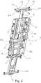
- the embodiment of the utility vehicle chassis after Fig. 1 has a compact tail 7, which is not rigid and therefore designed to be displaceable. Fig. 1 shows that this compact tail is designed so that it is inserted state very close to the rear wheels 2 and is partially above the rear region of the rear wheels 2 and the rear wheel cover 3 is located.
- the compact hatch is designed as a compact rear extension with an input and Ausschubbalken 8.
- a middle beam 9 with outer beam 9.1 is, which will be discussed in more detail.
- This center bar 9 extends with the spacing of the positions below the transversal traverse 5.1 and is held by brackets 10.
- This center bar 9 with the outer beam 9.1 provides an underrun protection dar.
- the Fig. 3 and 4 illustrate in different views an alternative embodiment according to Fig. 1 with non-telescopic compact tail.
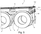
- Fig. 5 illustrates that in the embodiment according to Fig. 1 the rear crossbeam 5.1 above the rear wheels 2 and the wheel cover 3 are located, which is assigned to the rear wheels 2.
- the middle beam 9 is situated so far in the region of the chassis frame that the center beam 9 is located between the end region of the rear wheels 2 and the rear wheel covers 3.
- Fig. 6 where also outer panels 11 are shown, which are located in total behind the rear wheels 2 and the rear splash guard 3, so that the rear wheels 2 realize together with the outer panels 11 and the center beam 9 underrun protection.
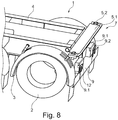
- Fig. 7 The outer beams 9.1 are located there in the inwardly pivoted position above the center bar 9 and are about the pivot lever 12 to pivot inwardly or outwardly about a pivot axis, the extends parallel to the commercial vehicle chassis longitudinal axis.
- Fig. 8 in another perspective view.
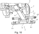
- the Fig. 9 shows the embodiment according to Fig. 2 with the slide-out compact tail 7 and the sliding bar. 8
- the compact rear 7 is designed as a compact rear extension, so that to transfer over the Ausschubbalken 8, the traverse crossbeam 5.1 in a recessed position is, so that the rear of a container structure is to be locked on the locking elements 5.2 with positional spacing, so that it is to unload and load at the rear flush.
- the outer beams 9.1 have been transferred via the pivoting angle 12 in their respective outward pivoted position so that they overlap with rear spacing of the rear wheels 2 and stiffen the outer panels 11. In this position they are to be locked.
- the Fig. 9 and Fig. 10 show in perspective detail the positions of the parts as they are in Fig. 2 and 9 are shown.
Landscapes
- Engineering & Computer Science (AREA)
- Mechanical Engineering (AREA)
- Chemical & Material Sciences (AREA)
- Combustion & Propulsion (AREA)
- Transportation (AREA)
- Body Structure For Vehicles (AREA)
Description
- Die Erfindung bezieht sich auf ein Nutzfahrzeugchassis mit einem Radachsen mit zugeordneten Rädern umfassenden Fahrgestellrahmen mit Längstraversen und Quertraversen, von denen eine den Fahrgestellrahmen heckseitig abschließende Heckquertraverse Teil eines Fahrgestellrahmenhecks ist und die Heckquertraverse und zumindest eine weitere Quertraverse Verriegelungselemente zur Verriegelung einer Nutzlast, insbesondere eines Containers aufweisen.
- Beim Transport von Gütern durch Nutzfahrzeuge ist anerkannt, dass die zulässige Nutzlast des Nutzfahrzeuges nicht überschritten werden darf, um die Verkehrs- und Betriebssicherheit nicht zu beeinträchtigen.
- Dabei ist die Lastverteilung von besonderer Bedeutung. Gleichwohl bedarf es bei der Beladung des Nutzfahrzeuges nicht ausschließlich der Berücksichtigung der maximalen Nutzlast, sondern auch einer exakten Positionierung der Nutzlast auf der entsprechenden Ladefläche, also dem Nutzfahrzeugchassis mit seinem Fahrgestellrahmen.
- Die Positionierung der Nutzlast auf der Ladefläche ist unter anderem abhängig von dem Schwerpunkt der Nutzlast, den zulässigen Achslasten und der sogenannten Sattellast, also der Last, die auf der Sattelkupplung der Zugmaschine liegt. Sowohl für die Sattellast als auch für die Antriebsachslast sind die gesetzlichen Vorschriften einzuhalten.
- Für den grenzüberschreitenden Verkehr wird gefordert, dass die Antriebsachsen der Zugmaschine mit nicht weniger als 25 % des Gesamtgewichts des Nutzfahrzeuges belastet sein dürfen. Das kann bei einer ungünstigen Positionierung der Nutzlast zu einer Über- oder Unterschreitung der zulässigen Lasten kommen, obwohl die zulässige Nutzlast nicht überschritten wurde. Eine Achslastüberschreitung kann beispielsweise Schäden an Reifen und Achsen hervorrufen. Achslastunterschreitungen hingegen wirken sich maßgeblich auf das Lenkverhalten oder ein Anfahrverhalten des Nutzfahrzeuges aus.
- Im Bereich des Containertransportes ist die Positionierung der Ladung durch Verriegelungspositionen der Verriegelungselemente am Fahrgestell fest vorgegeben.
- Es sind verschiedene Nutzfahrzeugchassis für den Containertransport bekannt, um die gesetzlichen Vorschriften für die Lastverteilung speziell für den Transport eines 20'-Containers einzuhalten. Der technische Aufwand der angebotenen Containerfahrgestelle mit entsprechenden Lösungsmöglichkeiten ist jedoch relativ hoch.
- So ist beispielsweise ein Nutzfahrzeugchassis für den Containertransport bekannt, das einen Fahrgestellrahmen für eine flexible Lastverteilung ermöglicht. Dabei werden zwei Fahrgestellrahmen ineinander verschoben, um die Position des geladenen Containers zu verändern. Solche Containerfahrgestelle, die einanderzuverschieben sind, werden als Sliding-Bogie-Trailer bezeichnet. Die mittige Transportstellung ermöglicht eine gleichmäßige Verteilung der Last auf die Achsen des Nutzfahrzeugchassis sowie des Nutzfahrzeuges. Zum Be- und Entladen können die Fahrgestellrahmen bei beladenen Containern ineinander verschoben werden, so dass der Container heckbündig an eine Verladerampe herangefahren werden kann.
- Darüber hinaus ist ein anderes Nutzfahrzeugchassis bekannt mit einem teleskopierbaren Fahrgestellrahmen. Dabei sind Längstraversen eines vorderen Teils des Fahrgestellrahmens in offene Längstraversen eines hinteren Teils des Fahrgestellrahmens zu teleskopieren. Nach Einnahme der gewählten Teleskopierstellung nach Beladung des Nutzfahrzeugs mit einem Container ist ein Positionswechsel des geladenen Containers allerdings nicht mehr möglich. Wird daher für eine gewählte Transportstellung eine gleichmäßige Lastverteilung auf die Achsen des Fahrgestells und des nutzenden Fahrzeuges realisiert, bei der der geladenen Container einen Abstand zum Fahrgestellrahmenheck aufweist, ist ein Positionswechsel des Containers nach der Verladung nicht mehr möglich. Eine heckbündige Positionierung zur Entladung kann daher nicht mehr eingenommen werden, wenn zuvor der Container für die Transportstellung nicht heckbündig geladen wurde.
- Bei beiden Gestaltungen des Nutzfahrzeugchassis der bekannten Arten sind darüber hinaus die gesetzlichen Vorschriften für einen Unterfahrschutz einzuhalten. Deshalb weisen die Heckquertraversen des Fahrgestellrahmenhecks bei beiden bekannten Alternativen der vorbekannten Nutzfahrzeugchassis einen Abstand zu den heckseitigen Rädern des Nutzfahrzeugchassis auf. Dies ist nachteilig und erfordert eine Vielzahl von Bauteilen, die sich auf die Gesamterstehungskosten des Nutzfahrzeugchassis nachteilig auswirken.
- Es ist Aufgabe der vorliegenden Erfindung, ein Nutzfahrzeugchassis zur Verfügung zu stellen, das eine heckbündige Be- und Entladung einer Nutzlast, insbesondere eines Containers, ermöglicht, das darüber hinaus jedoch auch in kostengünstiger Bauweise eine verbesserte Lastverteilung ermöglicht. Darüber hinaus sollen die gesetzlichen Rahmenbedingungen für einen Unterfahrschutz berücksichtigt sein.
- Zur Lösung dieser Aufgabe zeichnet sich das Fahrzeugchassis der eingangs genannten Art dadurch aus, dass das die Heckquertraverse umfassende Fahrgestellrahmenheck als Kompaktheck mit einem mit Abstand unterhalb der Heckquertraverse angeordneten und sich zwischen zwei heckseitigen Rädern und/oder sich zwischen den den heckseitigen Rädern zugeordneten Radabdeckungen erstreckenden Mittelbalken ausgebildet ist, wobei die Heckquertraverse zumindest bereichsweise oberhalb von den heckseitigen Rädern und/oder von den heckseitigen Rädern zugeordneten Radabdeckungen angeordnet ist.
- Damit ist ein Nutzfahrzeugchassis geschaffen, bei dem durch die kompakte Bauweise des Fahrgestellrahmenhecks als Kompaktheck die hintere Verriegelungsposition der Nutzlast, insbesondere also des Containers, näher an der letzten Achse der heckseitigen Räder platziert werden kann. Gleichwohl ist das Kompaktheck konstruktiv so zu gestalten, dass eine heckbündige Be- und Entladung eines Containers realisiert werden kann. Aufgrund der engen Platzierung eines Containers an der letzten Achse ist darüber hinaus die Lastverteilung auch bei heckbündiger Be- und Entladungsmöglichkeit des Containers wesentlich verbessert, da der Abstand des Schwerpunktes der Last (Ladung) vom Mittelpunkt des Achsaggregates vergrößert ist, wodurch die Sattellast erhöht wird.
- Darüber hinaus ist nur eine geringe Anzahl von Bauteilen notwendig. Daher ist diese erfindungsgemäße Gestaltung des Nutzfahrzeugchassis wesentlich kostengünstiger und weniger verschleißanfällig im Vergleich zu verschiebbaren Fahrgestellen insgesamt. Dieses ist insbesondere im Bereich des Containertransportes von wesentlichem Vorteil, da die Beanspruchung von Containerfahrgestellen bei der Verladung von Containern auf z. B. verschiedene Fahrgestelle sehr hoch ist.
- Trotz der Bauweise als Kompaktheck ist es aufgrund des vorgesehenen Mittelbalkens möglich, die gesetzlichen Regelungen für einen Unterfahrschutz einzuhalten, da in Verbindung mit den Mittelbalken die heckseitigen Räder der in Fahrzeuglängsrichtung letzten Achse zum Teil die Funktion des Unterfahrschutzes übernehmen. Um auch ein Unterfahren im Falle eines Unfalles im Bereich zwischen den Rädern zu vermeiden, ist der mit Lageabstand zur Hecktraverse unterhalb der Hecktraverse vorgesehene Mittelbalken vorgesehen.
- Besonders bevorzugt wird, wenn das Kompaktheck Teil eines Kompaktheckausschubes ist, das in seiner kürzesten Stellung, also der Stellung, in der die Heckquertraverse in Richtung der anderen Quertraversen des Fahrgestellrahmens verschoben ist, in der Stellung gelegen ist, in der sie sich zumindest bereichsweise oberhalb von heckseitigen Rädern und/oder von der heckseitigen Rädern zugeordneten Radabdeckungen befindet. Gleichwohl kann für den Transport von größeren Containern als 20'-Containern der Kompaktheckausschub dem heckseitigen Mittelbalken soweit hinaus geschoben werden, dass z. B. auch 30'-, 40'-, 45'-Container und andere geladen werden können, die dann auch heckbündig zu entladen und zu beladen sind. Die Fahrgestellrahmenteile sind dazu nicht zu verändern, so dass auf eine Vielzahl von Bauteilen in kostengünstigerer Weise gegenüber herkömmlichen Nutzfahrzeugchassisgestaltungen verzichtet werden kann. Die gesetzlichen Regelungen für den Unterfahrschutz sind dabei auch wiederum von dem Mittelbalken zu übernehmen, der dazu in bevorzugter Weise auch noch mit ausschwenkbaren Außenbalken versehen sein kann, die in ihrer ausgeschwenkten Stellung mit Abstand die heckseitigen Räder der letzten Radachse überlappen und mit z. B. Außenblechen zusammenwirken und diese aussteifen.
- Weitere vorteilhafte Ausgestaltungen sind weiteren Unteransprüchen, der nachfolgenden Beschreibung und den Zeichnungen zu entnehmen. Die Zeichnung zeigt:
- Fig. 1:
- ein Ausführungsbeispiel eines teleskopierbaren Nutzfahrzeugchassis nach der Erfindung mit einem Kompaktheck mit der Hecktraverse, die sich oberhalb der hinteren Räder und oberhalb der hinteren Radabdeckung befindet in eingefahrenem Zustand;
- Fig. 2:
- das Nutzfahrzeugchassis nach
Fig. 1 mit einem ein- und ausschiebbaren Kompaktheck mit Heckquertraverse und Mittelbalken und ausschwenkbaren Außenbalken im ausgefahrenen Zustand; - Fig. 3:
- ein alternatives Ausführungsbeispiel zu
Fig. 1 (nicht teleskopierbar) in einer perspektivischen Aufsicht von hinten; - Fig. 4:
- das Ausführungsbeispiel nach
Fig. 3 in einer perspektivischen Aufsicht von vorne; - Fig. 5:
- das Ausführungsbeispiel nach
Fig. 3 (teilweise) in einer perspektivischen Ansicht von der Seite; - Fig. 6:
- das Ausführungsbeispiel nach
Fig. 3 in einer perspektivischen Ansicht schräg von hinten; - Fig. 7:
- das Ausführungsbeispiel nach
Fig. 1 bzw. 2 mit einwärts verschwenkten Außenbalken; - Fig. 8:
- das Ausführungsbeispiel und die Lage des Heckausschubes nach
Fig. 7 in einer Seitendarstellung; - Fig. 9:
- das Ausführungsbeispiel nach
Fig. 1 bzw. 2 in einer ausgeschobenen Position des Kompakthecks, und - Fig. 10:
- der Kompaktheckausschub des Ausführungsbeispieles nach
Fig. 2 in einer Ansicht perspektivisch schräg von unten - In der Zeichnung sind übereinstimmende Teile mit übereinstimmenden Bezugsziffern versehen.
- In den Figuren ist allgemein mit 1 ein Nutzfahrzeugchassis beziffert, das in dem gezeigten Ausführungsbeispiel drei Radachsen mit zugeordneten Rädern 2, Radabdeckung 3 und Quertraversen 5 unter Einschluss einer Heckquertraverse 5.1 aufweist. Die Quertraversen 5 unter Einschluss der Heckquertraverse 5.1 weisen Verriegelungselemente 5.2 auf. Das Ausführungsbeispiel des Nutzfahrzeugchassis nach
Fig. 1 hat ein Kompaktheck 7, das nicht starr und mithin verschieblich ausgebildet ist.Fig. 1 zeigt, dass dieses Kompaktheck so ausgebildet ist, dass es eingeschobenen Zustand ganz nah an den heckseitigen Rädern 2 angeordnet ist und sich bereichsweise oberhalb des rückwärtigen Bereiches der heckseitigen Räder 2 bzw. der heckseitigen Radabdeckung 3 befindet. - In dem Ausführungsbeispiel nach
Fig. 2 ist das Kompaktheck als Kompaktheckausschub mit einem Ein- und Ausschubbalken 8 ausgebildet. Dort ist ersichtlich, dass sich mit Abstand unterhalb der Heckquertraverse 5.1 ein Mittelbalken 9 mit Außenbalken 9.1 befindet, worauf noch näher eingegangen wird. Dieser Mittelbalken 9 erstreckt sich mit Lageabstand unterhalb der Heckquertraverse 5.1 und ist über Konsolen 10 gehalten. Dieser Mittelbalken 9 mit den Außenbalken 9.1 stellt einen Unterfahrschutz dar. DieFig. 3 und4 verdeutlichen in verschiedenen Ansichten ein alternatives Ausführungsbeispiel nachFig. 1 mit nicht teleskopierbarem Kompaktheck. -
Fig. 5 verdeutlicht, dass sich in dem Ausführungsbeispiel nachFig. 1 die Heckquertraverse 5.1 oberhalb der heckseitigen Räder 2 bzw. der Radabdeckung 3 befinden, die den heckseitigen Rädern 2 zugeordnet ist. Der Mittelbalken 9 ist so weit im Bereich des Fahrgestellrahmens gelegen, dass sich der Mittelbalken 9 zwischen dem Endbereich der hinteren Räder 2 bzw. der heckseitigen Radabdeckungen 3 befindet. Dieses verdeutlicht auch noch einmalFig. 6 , wo auch Außenbleche 11 gezeigt sind, die sich insgesamt hinter den heckseitigen Rädern 2 bzw. den hinteren Spritzschutzblechen 3 befinden, so dass die hinteren Räder 2 zusammen mit den Außenblechen 11 und dem Mittelbalken 9 den Unterfahrschutz realisieren. -
Fig. 7 zeigt die einwärts verschwenkten Außenbalken 9.1 des Mittelbalkens 9 mit den zugeordneten Außenblechen 11. Die Außenbalken 9.1 befinden sich dort in der einwärts verschwenkten Lage oberhalb des Mittelbalkens 9 und sind über die Schwenkhebel 12 nach einwärts bzw. nach auswärts zu verschwenken um eine Schwenkachse, die sich parallel zur Nutzfahrzeugchassislängsachse erstreckt. Gleiches zeigt auch noch einmalFig. 8 in einer anderen perspektivischen Ansicht. DieFig. 9 zeigt das Ausführungsbeispiel nachFig. 2 mit dem ausschiebbaren Kompaktheck 7 und dem Schiebebalken 8. - Das Kompaktheck 7 ist als Kompaktheckausschub ausgebildet, so dass über den Ausschubbalken 8 die Heckquertraverse 5.1 in eine rückversetzte Stellung zu überführen ist, so dass über die Verriegelungselemente 5.2 mit Lageabstand das Heck eines Containeraufbaus zu verriegeln ist, so dass dieser heckbündig zu entladen und zu beladen ist.
- Die Außenbalken 9.1 sind über die Schwenkwinkel 12 in ihre jeweilige auswärts verschwenkte Position überführt worden, so dass sie mit Lageabstand die heckseitigen Räder 2 überlappen und die Außenbleche 11 aussteifen. In dieser Position sind sie zu verriegeln. Die
Fig. 9 undFig. 10 zeigen perspektivisch ausschnittsweise die Positionen der Teile, wie sie inFig. 2 und9 dargestellt sind.
Claims (9)
- Nutzfahrzeugchassis (1) mit einem Radachsen mit zugeordneten Rädern (2), umfassenden Fahrgestellrahmen mit Längstraversen (4) und Quertraversen (5, 5.1), von denen eine den Fahrgestellrahmen heckseitig abschließende Heckquertraverse (5.1) Teil eines Fahrgestellrahmenhecks ist und die Heckquertraverse (5.1) und zumindest eine weitere Quertraverse (5) Verriegelungselemente (5.2) zur Verriegelung einer Nutzlast, insbesondere eines Containers, aufweisen, dadurch gekennzeichnet, dass das die Heckquertraverse (5.1) umfassende Fahrgestellrahmenheck als Kompaktheck (7) mit einem mit Abstand unterhalb der Heckquertraverse (5.1) angeordneten und sich zwischen zwei heckseitigen Rädern (2) und/oder sich zwischen zwei den heckseitigen Rädern (2) zugeordneten Radabdeckungen (3) erstreckenden Mittelbalken (9) ausgebildet ist, wobei die Heckquertraverse (5.1) zumindest bereichsweise oberhalb von heckseitigen Rädern (2) und/oder von den heckseitigen Rädern (2) zugeordneten Radabdeckungen (3) angeordnet ist.
- Nutzfahrzeugchassis (1) nach Anspruch 1, dadurch gekennzeichnet, dass das Kompaktheck (7) mit der Heckquertraverse (5.1) und dem Mittelbalken (9) in Nutzfahrzeugchassislängsrichtung verschiebbar ausgebildet ist und der Mittelbalken (9) aus seiner Lage zwischen den heckseitigen Rädern (2) bzw. aus seiner Lage zwischen den den heckseitigen Rädern (2) zugeordneten Radabdeckungen (3) zusammen mit der Heckquertraverse (5.1) aus ihrer Lage zumindest bereichsweise oberhalb von heckseitigen Rädern (2) bzw. den heckseitigen Rädern (2) zugeordneten Radabdeckungen (3) in eine rückversetzte Lage überführbar ist und dass das Kompaktheck (7) mit der Hecktraverse (5.1) und dem heckseitigen Mittelbalken (9) Teil eines Kompaktheckausschubes sind.
- Nutzfahrzeugchassis (1) nach Anspruch 1 oder 2, dadurch gekennzeichnet, dass sich an den den Außenseiten des Mittelbalkens (9) Unterfahrschutzsicherungselemente (11) anschließen, die heckseitig die heckseitigen Räder (2) überlappen.
- Nutzfahrzeugchassis (1) nach Anspruch 3, dadurch gekennzeichnet, dass die Unterfahrschutzsicherungselemente (11) als Außenbleche ausgebildet sind.
- Nutzfahrzeugchassis nach einem der Ansprüche 1 bis 4, dadurch gekennzeichnet, dass der Mittelbalken (9) über Konsolen (10) an der Heckquertraverse (5.1) oder an Längstraversen (4) mit vertikalem Lageabstand zu dieser gehaltert ist.
- Nutzfahrzeugchassis (1) nach einem der Ansprüche 2 bis 5, dadurch gekennzeichnet, dass an dem Mittelbalken (9) an seiner jeweiligen Nutzfahrzeugchassisaußenseite ein verschwenkbarer oder verschiebbarer Außenbalken (9.1) vorgesehen ist.
- Nutzfahrzeugchassis nach Anspruch 6, d. g., da der Außenbalken (9.1) jeweils um eine parallel zur Nutzfahrzeugchassislängsachse parallele Schwenkachse einwärts und auswärts verschwenkbar ist, wobei der jeweilige Außenbalken (9.1) in der einwärts verschwenkten Lage oberhalb des Mittelbalkens (9) angeordnet ist und gemeinsam mit diesem in den eingeschobenen Zustand des Heckausschubs in die Position zwischen die heckseitigen Räder (2) bzw. zwischen die den heckseitigen Rädern (2) zugeordneten Radabdeckungen (3) überführbar ist.
- Nutzfahrzeugchassis (1) nach Anspruch 6 oder 7, dadurch gekennzeichnet, dass die jeweiligen Außenbalken (9.1) in ihrer auswärts verschwenkten oder ausgeschobenen Lage sich im Bereich des zugeordneten Unterfahrschutzsicherungselements (11) erstreckten und dieses aussteifen.
- Nutzfahrzeugchassis (1) nach Anspruch 6 oder 7, dadurch gekennzeichnet, dass die Außenbalken (9.1) in ihrer einwärts verschwenkten oder eingeschobenen Lage an dem Mittelbalken (9) verriegelbar sind.
Priority Applications (1)
| Application Number | Priority Date | Filing Date | Title |
|---|---|---|---|
| PL17001052T PL3260358T3 (pl) | 2016-06-24 | 2017-06-21 | Podwozie pojazdu użytkowego |
Applications Claiming Priority (1)
| Application Number | Priority Date | Filing Date | Title |
|---|---|---|---|
| DE102016007667.4A DE102016007667B3 (de) | 2016-06-24 | 2016-06-24 | Nutzfahrzeugchassis |
Publications (2)
| Publication Number | Publication Date |
|---|---|
| EP3260358A1 true EP3260358A1 (de) | 2017-12-27 |
| EP3260358B1 EP3260358B1 (de) | 2020-04-01 |
Family
ID=59152617
Family Applications (1)
| Application Number | Title | Priority Date | Filing Date |
|---|---|---|---|
| EP17001052.4A Active EP3260358B1 (de) | 2016-06-24 | 2017-06-21 | Nutzfahrzeugchassis |
Country Status (5)
| Country | Link |
|---|---|
| EP (1) | EP3260358B1 (de) |
| DE (1) | DE102016007667B3 (de) |
| DK (1) | DK3260358T3 (de) |
| ES (1) | ES2797744T3 (de) |
| PL (1) | PL3260358T3 (de) |
Cited By (1)
| Publication number | Priority date | Publication date | Assignee | Title |
|---|---|---|---|---|
| CN113428230A (zh) * | 2021-08-27 | 2021-09-24 | 沛县迅驰专用车辆制造有限公司 | 一种半挂车纵梁总成 |
Families Citing this family (1)
| Publication number | Priority date | Publication date | Assignee | Title |
|---|---|---|---|---|
| DE102023100305B3 (de) | 2023-01-09 | 2024-02-01 | Fahrzeugwerk Bernard Krone GmbH & Co. KG | Nutzfahrzeug mit beweglichem Heckausschub |
Citations (3)
| Publication number | Priority date | Publication date | Assignee | Title |
|---|---|---|---|---|
| US4836735A (en) * | 1988-03-11 | 1989-06-06 | Xtra Corporation | Load positioning container chassis |
| GB2468031A (en) * | 2009-02-20 | 2010-08-25 | Terry Deakin | Extendible width trailer for container handling |
| GB2523809A (en) * | 2014-03-06 | 2015-09-09 | Sdc Trailers Ltd | Trailer |
-
2016
- 2016-06-24 DE DE102016007667.4A patent/DE102016007667B3/de not_active Expired - Fee Related
-
2017
- 2017-06-21 EP EP17001052.4A patent/EP3260358B1/de active Active
- 2017-06-21 PL PL17001052T patent/PL3260358T3/pl unknown
- 2017-06-21 ES ES17001052T patent/ES2797744T3/es active Active
- 2017-06-21 DK DK17001052.4T patent/DK3260358T3/da active
Patent Citations (3)
| Publication number | Priority date | Publication date | Assignee | Title |
|---|---|---|---|---|
| US4836735A (en) * | 1988-03-11 | 1989-06-06 | Xtra Corporation | Load positioning container chassis |
| GB2468031A (en) * | 2009-02-20 | 2010-08-25 | Terry Deakin | Extendible width trailer for container handling |
| GB2523809A (en) * | 2014-03-06 | 2015-09-09 | Sdc Trailers Ltd | Trailer |
Cited By (1)
| Publication number | Priority date | Publication date | Assignee | Title |
|---|---|---|---|---|
| CN113428230A (zh) * | 2021-08-27 | 2021-09-24 | 沛县迅驰专用车辆制造有限公司 | 一种半挂车纵梁总成 |
Also Published As
| Publication number | Publication date |
|---|---|
| ES2797744T3 (es) | 2020-12-03 |
| PL3260358T3 (pl) | 2020-10-19 |
| DE102016007667B3 (de) | 2017-10-19 |
| DK3260358T3 (da) | 2020-07-13 |
| EP3260358B1 (de) | 2020-04-01 |
Similar Documents
| Publication | Publication Date | Title |
|---|---|---|
| DE1630282A1 (de) | Wahlweise als Einzelanhaenger an eine Strassenzugmaschine oder Tandemanhaenger hinter einen identischen Anhaenger ankuppelbare Fahrgestelleinheit | |
| EP3141455B1 (de) | Vorrichtung zum transport von stückgütern | |
| DE102009042287A1 (de) | Transportwagen | |
| EP3398810B1 (de) | Kompaktheck an nutzfahrzeugen mit ausfahrbarem heck | |
| DE102016007667B3 (de) | Nutzfahrzeugchassis | |
| DE202007017140U1 (de) | Wechselrahmensystem für Aufbauten von Kraftfahrzeugen | |
| DE2741125A1 (de) | Lastkraftwagen, insbesondere grossraumfahrzeug oder sattelschlepper | |
| EP3093220A1 (de) | Expandierbarer fahrzeuganhänger | |
| EP0528144A1 (de) | Sattelanhänger | |
| EP3581468B1 (de) | Chassisstruktur, cassisstruktursystem und chassis eines nutzfahrzeugs | |
| DE202013105357U1 (de) | Sicherungsvorrichtung für ein Lastfahrzeug | |
| DE102010046084B4 (de) | Nutzfahrzeug zum Transport von Containern | |
| DE2452821C3 (de) | Lastkraftfahrzeug | |
| DE3523742A1 (de) | Lastzug | |
| EP2380770B1 (de) | Transportfahrzeug, insbesondere Fahrzeugtransporter für Pkws | |
| DE102012108527B4 (de) | Lastfahrzeug mit einem Schutzrahmen | |
| DE202018102655U1 (de) | Vorrichtung zur Sicherung von Ladegut | |
| EP1604888B1 (de) | Verfahren zum Transport von Lenk- und Antriebseinheiten sowie Anordnung von Transporthilfsmitteln zu deren Transport auf einem Transportfahrzeug | |
| EP0162213B1 (de) | Vorrichtung zum Zuordnen eines gefedert bereiften Fahrzeuges zu einer Transportpalette | |
| DE10236335A1 (de) | PKW-Anhänger mit zwei Achsen | |
| DE2829420A1 (de) | Lastkraftfahrzeug | |
| EP4722083A1 (de) | System zur bereitstellung eines anhängers, anhänger sowie verfahren zur herstellung eines anhängers | |
| AT519909B1 (de) | Vorrichtung zur sicherung von ladegut | |
| EP2512905B1 (de) | Transportfahrzeug mit integriertem anhänger | |
| DE102024116810A1 (de) | Luftleitvorrichtung für ein Nutzfahrzeug und Nutzfahrzeug mit einer solchen Luftleitvorrichtung |
Legal Events
| Date | Code | Title | Description |
|---|---|---|---|
| PUAI | Public reference made under article 153(3) epc to a published international application that has entered the european phase |
Free format text: ORIGINAL CODE: 0009012 |
|
| STAA | Information on the status of an ep patent application or granted ep patent |
Free format text: STATUS: THE APPLICATION HAS BEEN PUBLISHED |
|
| AK | Designated contracting states |
Kind code of ref document: A1 Designated state(s): AL AT BE BG CH CY CZ DE DK EE ES FI FR GB GR HR HU IE IS IT LI LT LU LV MC MK MT NL NO PL PT RO RS SE SI SK SM TR |
|
| AX | Request for extension of the european patent |
Extension state: BA ME |
|
| STAA | Information on the status of an ep patent application or granted ep patent |
Free format text: STATUS: REQUEST FOR EXAMINATION WAS MADE |
|
| 17P | Request for examination filed |
Effective date: 20180216 |
|
| RBV | Designated contracting states (corrected) |
Designated state(s): AL AT BE BG CH CY CZ DE DK EE ES FI FR GB GR HR HU IE IS IT LI LT LU LV MC MK MT NL NO PL PT RO RS SE SI SK SM TR |
|
| STAA | Information on the status of an ep patent application or granted ep patent |
Free format text: STATUS: EXAMINATION IS IN PROGRESS |
|
| 17Q | First examination report despatched |
Effective date: 20181106 |
|
| GRAP | Despatch of communication of intention to grant a patent |
Free format text: ORIGINAL CODE: EPIDOSNIGR1 |
|
| STAA | Information on the status of an ep patent application or granted ep patent |
Free format text: STATUS: GRANT OF PATENT IS INTENDED |
|
| INTG | Intention to grant announced |
Effective date: 20191210 |
|
| GRAS | Grant fee paid |
Free format text: ORIGINAL CODE: EPIDOSNIGR3 |
|
| GRAA | (expected) grant |
Free format text: ORIGINAL CODE: 0009210 |
|
| STAA | Information on the status of an ep patent application or granted ep patent |
Free format text: STATUS: THE PATENT HAS BEEN GRANTED |
|
| AK | Designated contracting states |
Kind code of ref document: B1 Designated state(s): AL AT BE BG CH CY CZ DE DK EE ES FI FR GB GR HR HU IE IS IT LI LT LU LV MC MK MT NL NO PL PT RO RS SE SI SK SM TR |
|
| REG | Reference to a national code |
Ref country code: GB Ref legal event code: FG4D Free format text: NOT ENGLISH |
|
| REG | Reference to a national code |
Ref country code: CH Ref legal event code: EP Ref country code: AT Ref legal event code: REF Ref document number: 1251008 Country of ref document: AT Kind code of ref document: T Effective date: 20200415 |
|
| REG | Reference to a national code |
Ref country code: DE Ref legal event code: R096 Ref document number: 502017004416 Country of ref document: DE |
|
| REG | Reference to a national code |
Ref country code: IE Ref legal event code: FG4D Free format text: LANGUAGE OF EP DOCUMENT: GERMAN |
|
| REG | Reference to a national code |
Ref country code: DK Ref legal event code: T3 Effective date: 20200708 |
|
| REG | Reference to a national code |
Ref country code: SE Ref legal event code: TRGR |
|
| REG | Reference to a national code |
Ref country code: NL Ref legal event code: FP |
|
| PG25 | Lapsed in a contracting state [announced via postgrant information from national office to epo] |
Ref country code: BG Free format text: LAPSE BECAUSE OF FAILURE TO SUBMIT A TRANSLATION OF THE DESCRIPTION OR TO PAY THE FEE WITHIN THE PRESCRIBED TIME-LIMIT Effective date: 20200701 |
|
| REG | Reference to a national code |
Ref country code: LT Ref legal event code: MG4D |
|
| PG25 | Lapsed in a contracting state [announced via postgrant information from national office to epo] |
Ref country code: LT Free format text: LAPSE BECAUSE OF FAILURE TO SUBMIT A TRANSLATION OF THE DESCRIPTION OR TO PAY THE FEE WITHIN THE PRESCRIBED TIME-LIMIT Effective date: 20200401 Ref country code: PT Free format text: LAPSE BECAUSE OF FAILURE TO SUBMIT A TRANSLATION OF THE DESCRIPTION OR TO PAY THE FEE WITHIN THE PRESCRIBED TIME-LIMIT Effective date: 20200817 Ref country code: FI Free format text: LAPSE BECAUSE OF FAILURE TO SUBMIT A TRANSLATION OF THE DESCRIPTION OR TO PAY THE FEE WITHIN THE PRESCRIBED TIME-LIMIT Effective date: 20200401 Ref country code: CZ Free format text: LAPSE BECAUSE OF FAILURE TO SUBMIT A TRANSLATION OF THE DESCRIPTION OR TO PAY THE FEE WITHIN THE PRESCRIBED TIME-LIMIT Effective date: 20200401 Ref country code: IS Free format text: LAPSE BECAUSE OF FAILURE TO SUBMIT A TRANSLATION OF THE DESCRIPTION OR TO PAY THE FEE WITHIN THE PRESCRIBED TIME-LIMIT Effective date: 20200801 Ref country code: NO Free format text: LAPSE BECAUSE OF FAILURE TO SUBMIT A TRANSLATION OF THE DESCRIPTION OR TO PAY THE FEE WITHIN THE PRESCRIBED TIME-LIMIT Effective date: 20200701 Ref country code: GR Free format text: LAPSE BECAUSE OF FAILURE TO SUBMIT A TRANSLATION OF THE DESCRIPTION OR TO PAY THE FEE WITHIN THE PRESCRIBED TIME-LIMIT Effective date: 20200702 |
|
| PG25 | Lapsed in a contracting state [announced via postgrant information from national office to epo] |
Ref country code: LV Free format text: LAPSE BECAUSE OF FAILURE TO SUBMIT A TRANSLATION OF THE DESCRIPTION OR TO PAY THE FEE WITHIN THE PRESCRIBED TIME-LIMIT Effective date: 20200401 Ref country code: RS Free format text: LAPSE BECAUSE OF FAILURE TO SUBMIT A TRANSLATION OF THE DESCRIPTION OR TO PAY THE FEE WITHIN THE PRESCRIBED TIME-LIMIT Effective date: 20200401 Ref country code: HR Free format text: LAPSE BECAUSE OF FAILURE TO SUBMIT A TRANSLATION OF THE DESCRIPTION OR TO PAY THE FEE WITHIN THE PRESCRIBED TIME-LIMIT Effective date: 20200401 |
|
| REG | Reference to a national code |
Ref country code: ES Ref legal event code: FG2A Ref document number: 2797744 Country of ref document: ES Kind code of ref document: T3 Effective date: 20201203 |
|
| PG25 | Lapsed in a contracting state [announced via postgrant information from national office to epo] |
Ref country code: AL Free format text: LAPSE BECAUSE OF FAILURE TO SUBMIT A TRANSLATION OF THE DESCRIPTION OR TO PAY THE FEE WITHIN THE PRESCRIBED TIME-LIMIT Effective date: 20200401 |
|
| REG | Reference to a national code |
Ref country code: DE Ref legal event code: R097 Ref document number: 502017004416 Country of ref document: DE |
|
| PG25 | Lapsed in a contracting state [announced via postgrant information from national office to epo] |
Ref country code: RO Free format text: LAPSE BECAUSE OF FAILURE TO SUBMIT A TRANSLATION OF THE DESCRIPTION OR TO PAY THE FEE WITHIN THE PRESCRIBED TIME-LIMIT Effective date: 20200401 Ref country code: EE Free format text: LAPSE BECAUSE OF FAILURE TO SUBMIT A TRANSLATION OF THE DESCRIPTION OR TO PAY THE FEE WITHIN THE PRESCRIBED TIME-LIMIT Effective date: 20200401 Ref country code: SM Free format text: LAPSE BECAUSE OF FAILURE TO SUBMIT A TRANSLATION OF THE DESCRIPTION OR TO PAY THE FEE WITHIN THE PRESCRIBED TIME-LIMIT Effective date: 20200401 Ref country code: MC Free format text: LAPSE BECAUSE OF FAILURE TO SUBMIT A TRANSLATION OF THE DESCRIPTION OR TO PAY THE FEE WITHIN THE PRESCRIBED TIME-LIMIT Effective date: 20200401 |
|
| REG | Reference to a national code |
Ref country code: CH Ref legal event code: PL |
|
| PLBE | No opposition filed within time limit |
Free format text: ORIGINAL CODE: 0009261 |
|
| STAA | Information on the status of an ep patent application or granted ep patent |
Free format text: STATUS: NO OPPOSITION FILED WITHIN TIME LIMIT |
|
| PG25 | Lapsed in a contracting state [announced via postgrant information from national office to epo] |
Ref country code: SK Free format text: LAPSE BECAUSE OF FAILURE TO SUBMIT A TRANSLATION OF THE DESCRIPTION OR TO PAY THE FEE WITHIN THE PRESCRIBED TIME-LIMIT Effective date: 20200401 |
|
| 26N | No opposition filed |
Effective date: 20210112 |
|
| PG25 | Lapsed in a contracting state [announced via postgrant information from national office to epo] |
Ref country code: LU Free format text: LAPSE BECAUSE OF NON-PAYMENT OF DUE FEES Effective date: 20200621 |
|
| PG25 | Lapsed in a contracting state [announced via postgrant information from national office to epo] |
Ref country code: CH Free format text: LAPSE BECAUSE OF NON-PAYMENT OF DUE FEES Effective date: 20200630 Ref country code: LI Free format text: LAPSE BECAUSE OF NON-PAYMENT OF DUE FEES Effective date: 20200630 Ref country code: IE Free format text: LAPSE BECAUSE OF NON-PAYMENT OF DUE FEES Effective date: 20200621 |
|
| PG25 | Lapsed in a contracting state [announced via postgrant information from national office to epo] |
Ref country code: SI Free format text: LAPSE BECAUSE OF FAILURE TO SUBMIT A TRANSLATION OF THE DESCRIPTION OR TO PAY THE FEE WITHIN THE PRESCRIBED TIME-LIMIT Effective date: 20200401 |
|
| PG25 | Lapsed in a contracting state [announced via postgrant information from national office to epo] |
Ref country code: MT Free format text: LAPSE BECAUSE OF FAILURE TO SUBMIT A TRANSLATION OF THE DESCRIPTION OR TO PAY THE FEE WITHIN THE PRESCRIBED TIME-LIMIT Effective date: 20200401 Ref country code: CY Free format text: LAPSE BECAUSE OF FAILURE TO SUBMIT A TRANSLATION OF THE DESCRIPTION OR TO PAY THE FEE WITHIN THE PRESCRIBED TIME-LIMIT Effective date: 20200401 |
|
| PG25 | Lapsed in a contracting state [announced via postgrant information from national office to epo] |
Ref country code: MK Free format text: LAPSE BECAUSE OF FAILURE TO SUBMIT A TRANSLATION OF THE DESCRIPTION OR TO PAY THE FEE WITHIN THE PRESCRIBED TIME-LIMIT Effective date: 20200401 |
|
| P01 | Opt-out of the competence of the unified patent court (upc) registered |
Effective date: 20230518 |
|
| PGFP | Annual fee paid to national office [announced via postgrant information from national office to epo] |
Ref country code: PL Payment date: 20250606 Year of fee payment: 9 Ref country code: DE Payment date: 20250618 Year of fee payment: 9 |
|
| PGFP | Annual fee paid to national office [announced via postgrant information from national office to epo] |
Ref country code: GB Payment date: 20250620 Year of fee payment: 9 Ref country code: DK Payment date: 20250618 Year of fee payment: 9 |
|
| PGFP | Annual fee paid to national office [announced via postgrant information from national office to epo] |
Ref country code: NL Payment date: 20250618 Year of fee payment: 9 Ref country code: BE Payment date: 20250617 Year of fee payment: 9 |
|
| PGFP | Annual fee paid to national office [announced via postgrant information from national office to epo] |
Ref country code: FR Payment date: 20250626 Year of fee payment: 9 |
|
| PGFP | Annual fee paid to national office [announced via postgrant information from national office to epo] |
Ref country code: AT Payment date: 20250616 Year of fee payment: 9 |
|
| PGFP | Annual fee paid to national office [announced via postgrant information from national office to epo] |
Ref country code: TR Payment date: 20250618 Year of fee payment: 9 |
|
| PGFP | Annual fee paid to national office [announced via postgrant information from national office to epo] |
Ref country code: SE Payment date: 20250618 Year of fee payment: 9 |
|
| PGFP | Annual fee paid to national office [announced via postgrant information from national office to epo] |
Ref country code: ES Payment date: 20250718 Year of fee payment: 9 |
|
| PGFP | Annual fee paid to national office [announced via postgrant information from national office to epo] |
Ref country code: IT Payment date: 20250630 Year of fee payment: 9 |