EP3269889B1 - Système de connexion - Google Patents
Système de connexion Download PDFInfo
- Publication number
- EP3269889B1 EP3269889B1 EP16179323.7A EP16179323A EP3269889B1 EP 3269889 B1 EP3269889 B1 EP 3269889B1 EP 16179323 A EP16179323 A EP 16179323A EP 3269889 B1 EP3269889 B1 EP 3269889B1
- Authority
- EP
- European Patent Office
- Prior art keywords
- building
- holding section
- component
- timber
- contact surface
- Prior art date
- Legal status (The legal status is an assumption and is not a legal conclusion. Google has not performed a legal analysis and makes no representation as to the accuracy of the status listed.)
- Active
Links
Images


Classifications
-
- E—FIXED CONSTRUCTIONS
- E04—BUILDING
- E04B—GENERAL BUILDING CONSTRUCTIONS; WALLS, e.g. PARTITIONS; ROOFS; FLOORS; CEILINGS; INSULATION OR OTHER PROTECTION OF BUILDINGS
- E04B1/00—Constructions in general; Structures which are not restricted either to walls, e.g. partitions, or floors or ceilings or roofs
- E04B1/02—Structures consisting primarily of load-supporting, block-shaped, or slab-shaped elements
- E04B1/10—Structures consisting primarily of load-supporting, block-shaped, or slab-shaped elements the elements consisting of wood
-
- E—FIXED CONSTRUCTIONS
- E04—BUILDING
- E04B—GENERAL BUILDING CONSTRUCTIONS; WALLS, e.g. PARTITIONS; ROOFS; FLOORS; CEILINGS; INSULATION OR OTHER PROTECTION OF BUILDINGS
- E04B1/00—Constructions in general; Structures which are not restricted either to walls, e.g. partitions, or floors or ceilings or roofs
- E04B1/003—Balconies; Decks
- E04B1/0038—Anchoring devices specially adapted therefor with means for preventing cold bridging
-
- E—FIXED CONSTRUCTIONS
- E04—BUILDING
- E04B—GENERAL BUILDING CONSTRUCTIONS; WALLS, e.g. PARTITIONS; ROOFS; FLOORS; CEILINGS; INSULATION OR OTHER PROTECTION OF BUILDINGS
- E04B1/00—Constructions in general; Structures which are not restricted either to walls, e.g. partitions, or floors or ceilings or roofs
- E04B1/18—Structures comprising elongated load-supporting parts, e.g. columns, girders, skeletons
- E04B1/26—Structures comprising elongated load-supporting parts, e.g. columns, girders, skeletons the supporting parts consisting of wood
- E04B1/2604—Connections specially adapted therefor
- E04B2001/2644—Brackets, gussets or joining plates
- E04B2001/2648—Brackets, gussets or joining plates located in slots of the elongated wooden members
Definitions
- the present invention relates to a connection system for connecting a wooden structural element to a building element.
- the invention further relates to a timber construction connection comprising at least one such connection system.
- the invention relates to a building comprising at least one such connection system.
- connection systems for connecting a building to a cantilevered component which avoid local cold bridges, are well known.
- the thermal decoupling of the outer shell of the building and the cantilevered component means that an insulation layer can be attached or implemented without interruption.
- U1 discloses a connection system for connecting a wooden structural element to a reinforced concrete ceiling.
- U.S. 8,896,441 discloses a connection system for connecting a wooden structural element to a building element with a coupling element for pivoting the wooden structural element relative to the building element.
- the object of the present invention is to provide a connection system for timber construction which addresses the problems mentioned above.
- the problem of increased air convection, the interchangeability of the cantilever components, and the thermal decoupling of the cantilever component should be solved.
- connection system for connecting a wooden construction element to a building element according to claim 1, characterized by a first holding section for the building element, a second holding section for the wooden construction element, a coupling element which releasably connects the first holding section and the second holding section to one another, wherein the second holding section has (i) a fitting on the wood component side with a first contact surface for attachment to a first surface of the wood component and (ii) a second contact surface for a second surface of the wood component, the first contact surface of the fitting on the wood component side and the second contact surface of the second holding section enclose an angle ⁇ different from 180 ° with one another.
- the building element is preferably also a wooden construction element, for example a floor ceiling.
- connection system is on the one hand attached to the building, such as a floor ceiling, via the first holding section, preferably via a fitting on the building side.
- the wooden structural element such as a balcony or balcony support, is fastened via the fitting on the wooden structural element side, so that the building and wooden structural element are connected via the connecting element.
- the connection is a detachable connection. This means that the connection of the two holding sections can be released without one of the holding sections being destroyed, for example via a screw connection, rivets or the like.
- connection system makes it possible for the fitting on the building side to be initially attached to the building with an airtight element.
- the building's own airtight layer is connected to the airtight element, for example by means of gluing.
- the airtight layer can have a film and / or thermal and / or acoustic insulation elements that are applied to the building.
- the wooden structural element can then be fastened to the building via the wooden structural element-side fitting by connecting the two fittings to one another via the coupling element.
- the connection between the two fittings is detachable, but also rigid and rigid.
- a detachable connection can be a screw connection.
- Other types of connections are also conceivable, e.g. a hook connection, a form-fitting connection such as a dovetail connection.
- a rigid connection is one in which the deformations are so small that the force application points experience negligible displacements. At most, such rigid connections comprise damped elastic connections that result from structure-borne sound insulation.
- the holding section encompasses the wooden component at two contact surfaces, which enables an ideal flow of forces within the connection system.
- the first holding portion (i) a building-side fitting with a first building-side contact surface for attachment to a first surface of the building element and (ii) a second building-side contact surface for a second surface of the building element, the first building-side contact surface of the building-side fitting and the second building-side contact surface of the first holding section enclose an angle ⁇ different from 180 ° with one another.
- the design variants described so far enable an ideal flow of forces between the elements to be connected.
- high bending stresses occur due to the customary slim cross-sectional shapes of the wooden structural element.
- the second holding section has a fitting on the wooden component side with a contact surface for attachment to a first surface of the wooden component and a contact surface for a Having the second surface of the wooden component, these surfaces being arranged at an angle ⁇ other than 180 ° to one another, these bending moments can be ideally transferred from the wooden component-side fitting via the coupling element to the building element. This also enables timber construction elements that protrude far.
- the first holding section has a building-side fitting with a contact surface for attachment to a first surface of the building element and a contact surface for a second surface of the building element, and if here too the contact surface of the building-side fitting and the other contact surface have an angle ⁇ of 180 ° with one another include, these forces can also be ideally transferred.
- the angle ⁇ and / or the angle ⁇ are approximately between 45 ° and 135 °, preferably approximately 90 °.
- wooden construction elements are usually manufactured with surfaces arranged at right angles to one another, so that there are also technical production advantages.
- first contact surface of the fitting on the building side and the first contact surface of the fitting on the wood component side are arranged essentially parallel to one another or lie essentially in one plane.
- the variant that the contact surfaces lie approximately in one plane or only have an offset (and thus a parallel arrangement) of less than 100% of the thickness of the wooden construction element has advantages for the transmission of forces.
- the fitting on the building side and the fitting on the wooden component side can be arranged essentially parallel to one another or lie essentially in one plane.
- One embodiment variant provides that the second contact surface of the second holding section and the second contact surface of the first holding section are arranged essentially parallel to one another. These two contact surfaces are thus arranged at a distance from one another. This has the advantage that further elements, in particular insulating elements, plaster, fire protection elements or the like, can be introduced into this distance.
- the wooden construction element comes to lie at a distance D from the building element, so that a thermal insulation element and / or another one between the wooden construction element and the building element Facade element - such as a plaster layer or fire protection panels - can be introduced.
- the fitting on the building side is designed such that it can be connected to the building element by means of at least one fastening means, and that the fitting on the wooden component side can be connected to the wooden component by means of at least one fastening means.
- This enables simple assembly of the wooden structural element and the building element.
- bores can be provided through which the fastening means can be introduced and introduced into the timber structure or building element.
- the fastening means can be pin-shaped, e.g. be screws, nails, bolts or the like.
- other types of fastening can also be provided, e.g. Brackets, brackets, glue etc.
- the respective fitting has guides for - preferably pin-shaped - fastening means, so that the fastening means can be introduced at a defined spatial angle y, ⁇ to the respective contact surface of the fitting.
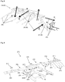
- At least some of the guides of the fastener guides can be designed in such a way that, in the installed state, the respective pin-shaped fasteners penetrate the respective component at an angle to the contact surface on the fitting, preferably at a spatial angle y, ⁇ between 30 degrees and 60 degrees ( Fig. 4 ). This is particularly advantageous if wooden construction or building elements are made of cross-laminated timber, as this ensures stable and secure anchoring. Glued laminated timber or unglued timber can also be securely fastened in this way.
- an adjusting device is provided with which the angle of inclination ⁇ between the second contact surface of the second holding section and the second building-side contact surface of the first holding section can be adjusted. In this way, load-related or production-related inclinations between the wooden construction element and the building element can be compensated.
- the adjusting device has an adjusting element with which a distance d between the first holding section and the second holding section can be changed.
- the contact surfaces of the two holding sections arranged parallel to each other form a profile with two legs via the coupling element, e.g. a U or V profile (the orientation of the profile is irrelevant), the leg ends being variable in distance via the adjusting element.
- the adjusting device can be fastened at a first connection point on the building-side fitting and at a distance at a second connection point on the wooden component-side fitting, the adjusting device having an adjusting element with which the distance d between the two connection points can be changed.
- the adjusting device can also have a joint section with which the angle of inclination ⁇ can be adjusted.
- an articulated adjusting element could be provided which has a spherical cap, by means of which at least the angle of inclination between the fitting on the building side and the fitting on the wooden component side can be adjusted about an axis of rotation A formed by means of a spherical cap.
- the adjusting element can have an adjusting device which has a tension screw, a pressure screw, an eccentric or a combination thereof, which is received by the adjusting element by means of a spherical cap, cylinder segment or the like.
- an airtight element is attached to the first holding section, to which the building-side airtight layer is attached, for example by means of gluing.
- connection system can be designed such that the coupling element can be detachably and essentially rigidly connected to the fitting on the building side, the fitting on the wood component side, or both.
- the coupling element can be separated from the two fittings.
- the coupling element is inextricably connected to the fitting on the building side and is releasably and essentially rigidly connected to the fitting on the wooden component side.
- This variant has the advantage that the fitting on the building side can be fastened to the building on the one hand and the fitting on the wooden component side can be fastened on the other hand to the wooden component, whereupon the two fittings are connected to one another so that the wooden component can be assembled quickly.
- the detachable connection of the fitting on the building side and the fitting on the wooden component side can, for example, also take place in such a way that the wooden component is also fastened at the same time.
- a screw can be provided with which the two fittings are connected to one another, in that the screw is guided through receptacles in the two fittings (for example holes) and is screwed into the wooden component.
- the coupling element and the fitting on the wooden component side have sections that interlock in a form-fitting manner such that at least part of the load transfer from the fitting on the timber component side to the coupling element takes place via this form-fitting.
- the coupling element preferably has recesses and a plurality of legs which enable an ideal flow of force.
- a stiffening element is therefore provided in order to increase the stability of the coupling element.
- the coupling element has parallel legs, the stiffening element connecting the two legs to one another.
- the wooden component-side fitting in the assembled state can be connected to the wooden component in a hanging manner from the wooden component-side fitting.
- a wood construction connection which has a connection system of the aforementioned type, the wood component-side fitting and the building-element-side fitting being connected to the coupling element, a wood construction element which is connected to the wood component-side fitting by means of at least one fastening means, and a building element , which is connected to the building element-side fitting by means of a fastening means.
- Figures 1a and 1b show a wood construction connection according to the prior art in cross section and in an oblique view.
- a cantilevered wooden construction element 3 is connected to a building element 5 in that the cantilevered wooden construction element 3 penetrates the building element 5.
- air flows are indicated by arrows. An air flow that hits the joint between the wooden structural element 3 and the building element 5 can enter the interior of the building due to the lack of airtight layer.
- Fig. 2 shows a timber construction connection according to the invention.
- the connection system 1 is shown without a wooden structural element 3 and a building element 5 (see also Figures 5 and 6 ) and it has a first holding section 13 for the building element 5 and a second holding section 14 for the wooden construction element 3.
- the actual coupling element 15 is shown, which releasably connects the first holding section 13 and the second holding section 14 to one another.
- the second holding section 14 is fastened to the first holding section 13 with coupling screws 23.
- the second holding section 14 has a fitting 20 on the wood component side with a first contact surface 30 for fastening to a first surface of the wood component 3.
- the wooden structural element 3 is placed on the contact surface 30 and fixed by means of fastening means 40.
- the second holding section 14 on the wooden component side has a second contact surface 31 for a second surface of the wooden component 3. The wooden structural element 3 rests against the second contact surface 31 at this point and thus ensures a force dissipation into the coupling element 15 towards the first holding section 13.
- the first holding section 13 has a fitting 19 on the building side with a first contact surface 32 for fastening to a first contact surface 32 of the building element 5 on the building side.
- This holding section 13 is also fastened by means of fastening means 40 (e.g. screws), the building element 5 being fastened at this point.
- the first holding section 13 also has a second contact surface 33 for a second building-side surface 33 of the building element 5.
- connection system 1 of the Fig. 2 The first contact surface 32 of the fitting 19 on the building side and the first contact surface 30 of the fitting 20 on the wood component side lie in one plane. In the embodiment of Fig. 7 these two contact surfaces 30, 32 are arranged parallel to one another and have an offset ⁇ h.
- connection system 1 of Fig. 2 furthermore has an arrangement of the second contact surface 31 of the second holding section 14 and the second contact surface 33 of the first holding section 13 parallel at a distance D. It would thus be possible to introduce a thermal insulation element 7 between the two holding sections 13, 14 in the area of the coupling element 15.
- Timber structure 3 and building element 5 are connected to the connection system 1 by several fastening means 40.
- pin-shaped fastening means 40 such as screws (shown), nails, bolts, and clips, but also flat fastening means 40 such as epoxy resin adhesive or the like.
- the respective fitting 19, 20 has fastening means guides 41 so that they can be introduced at angles y, ⁇ to the respective contact surface 30, 32 or 31, 32 of the fitting 19, 20, which are adapted to the required load-bearing and rigidity behavior are.
- the angles y, ⁇ are shown here at approximately 45 °.
- An adjusting device 26 is provided in the area of the coupling element 15. With this, the angle of inclination ⁇ between the legs 22a, 22b of the coupling element 15 can be adjusted. If the angles ⁇ and ⁇ (as in Fig. 2 in contrast to Fig. 3 ) shown enclose an angle of 90 °, the first contact surface 33 of the first holding portion 13 are in the same plane as the first leg 23a and the contact surface 31 of the second holding portion 14 in the same plane as the second leg 23b of the coupling element.
- the angle of inclination ⁇ for common areas of application is usually 0 ° (parallel arrangement of the legs 23a, 23b of the coupling element 15), but can also deviate therefrom due to the load or construction.
- this angle of inclination ⁇ can be set to the desired value.
- an inclination can be compensated in order to arrange the contact surfaces 31 and 33 parallel again, or a desired inclination could be introduced if the wooden construction element, for example, as a canopy ( Fig. 10 , bottom right) and an inclination angle ⁇ other than 0 ° is desired.
- the adjusting device 26 has an adjusting element 27 with which a distance d between the first holding section 13 and the second holding section 14 can be changed.
- the angle between the legs 23a, 23b of the coupling element 15 can be adjusted.
- the inclination of the legs 22a, 22b, which are arranged in a U-shape relative to one another, is changed.
- the wooden structural element 3 is spaced apart from the building element 5 by a distance D so that a thermal insulation element 7 and / or another facade element 8 - such as a layer of plaster or fire protection panels - can be inserted between the wooden structural element 3 and the building element 5.
- a thermal insulation element 7 and / or another facade element 8 - such as a layer of plaster or fire protection panels - can be inserted between the wooden structural element 3 and the building element 5.
- the stiffening element 29 for a better flow of force between the two holding sections 13, 14 can also be seen.
- Fig. 3 shows power flows within the connection system 1, which arise due to the loads on the wooden element 3 or the building element 5, bending moment and transverse forces on the respective holding section 13, 14 to be able to transmit. Due to the arrangement of the contact surfaces between the fittings 19, 20 and the elements 3, 5 to be connected, the bending moment is divided into several tensile and compression components F 1 , F 2 , F 3 , which activates several load-bearing reserves of the base material . As a result, an exclusive bending stress on the holding sections 13, 14 is prevented.
- the power transmission between the wooden element 3 and the building element 5 takes place through the coupling element 15.
- the bending moment and transverse force loads mainly cause tensile and compressive forces F 1 in the coupling element 15.
- the tensile force is transferred from the holding section 13 to the holding section 14 by the adjusting element 26, and the compressive force is transmitted from the wooden construction element 3 to the building element 5 via the contact surfaces 32 and 33.
- a secondary bending moment is broken down into a force component F 2 , F 3 , the tensile component through the fastening means 40 and the pressure component through the contact surfaces 30, 31, 32, 33 in the element to be connected (wooden construction element 3, building element 5) are transferred.
- Fig. 4 shows an alternative embodiment of the connection system 1.
- the same components are provided with the same reference symbols in all figures, so that the Figure description of the other figures may be referenced and only the differences are described.
- the exemplary embodiment shown also has a third contact surface 34 on the fitting 20 on the wood component side, against which the wood component 3 can rest.
- the connection system 1 is designed to be wider, so that the stiffening elements 29 are no longer designed in just one plane but in the form of pins in two planes.
- the detachable fastening consists of a plug connection (form fit) which provides a support 44 so that the wooden structural element 3 with the pre-assembled wooden structural fitting 20 on the first holding section 13 can be mounted on the building's fitting 19 of the building element 5.
- FIG. 1 shows the connection system 1 of FIG Fig. 2 with a wooden construction element 3 and a building element 5 with the continuous airtight level in between, formed from an airtightness element 16 in the area of the coupling element 15 and the building's own airtightness layer 17, as well as the insulating element 7 arranged in between, and the attachment of any facade element 8 the arrangement of a fire protection element 6 is shown on the underside of the coupling element 15.
- Fig. 7 shows a very similar connection system 1 as in FIG Fig. 2 or 4th with the difference that in connection system 1 the Fig. 2 the first contact surface 32 of the fitting 19 on the building side and the first contact surface 30 of the fitting 20 on the wood component side lie in one plane, while in the embodiment of FIG Fig. 7 these two contact surfaces 30, 32 are arranged parallel to one another and have an offset ⁇ h.
- Fig. 8 shows a connection system 1 according to the invention, in which, in addition to the thermal and air convective decoupling, the possibility is shown how corresponding improvements in sound insulation can be achieved by means of inserts of structure-borne sound insulation elements 9.
- Fig. 9 shows an articulated actuator in three different positions.
- the adjusting element has a spherical cap 28 and enables the angle of inclination to be adjusted between the fitting 19 on the building element side and the fitting 20 on the wood construction element side about an axis of rotation A formed by means of a spherical cap 27.
- Fig. 10 describes a building with connection systems 1 according to the invention, with different possible uses being shown.
- Possibilities for the application are, for example, balcony fastenings, false ceiling fastenings, canopy fastenings or roof fastenings.
Landscapes
- Engineering & Computer Science (AREA)
- Architecture (AREA)
- Physics & Mathematics (AREA)
- Electromagnetism (AREA)
- Civil Engineering (AREA)
- Structural Engineering (AREA)
- Life Sciences & Earth Sciences (AREA)
- Wood Science & Technology (AREA)
- Joining Of Building Structures In Genera (AREA)
Claims (13)
- Système d'assemblage (1) permettant l'assemblage d'un élément de construction en bois (3) à un élément de bâtiment (5), comprenant:une première partie de retenue (13) pour l'élément de bâtiment (5),une deuxième partie de retenue (14) pour l'élément de construction en bois (3),un élément d'accouplement (15), lequel relie la première partie de retenue (13) et la deuxième partie de retenue (14) l'une à l'autre de manière détachable à l'aide d'un assemblage détachable,la première partie de retenue (13) comprenant:(i) une ferrure (19) côté bâtiment pourvue d'une première surface de contact (32) destinée à être fixée à une première surface de l'élément de bâtiment (5) et(ii) une deuxième surface de contact (33) pour une deuxième surface de l'élément de bâtiment (5),la première surface de contact (32) de la ferrure (19) côté bâtiment et la deuxième surface de contact (33) de la première partie de retenue (13) formant ensemble un angle (β) différent de 180°,la deuxième partie de retenue (14) comprenant:(i) une ferrure (20) côté élément de construction en bois pourvue d'une première surface de contact (30) destinée à être fixée à une première surface de l'élément de construction en bois (3), et(ii) une deuxième surface de contact (31) pour une deuxième surface de l'élément de construction en bois (3),la première surface de contact (30) de la ferrure (20) côté élément de construction en bois et la deuxième surface de contact (31) de la deuxième partie de retenue (14) formant ensemble un angle (α) différent de 180°,l'élément d'accouplement (15) comprenant des branches (22a, 22b) parallèles et un élément de renforcement (29) reliant les branches (22a, 22b) entre elles,l'angle (α) et/ou l'angle (β) étant compris environ entre 45° et 180°, de préférence environ 90°,
caractérisé en ce que l'élément d'accouplement (15) relie en outre la première partie de retenue (13) et la deuxième partie de retenue (14) l'une à l'autre de manière résistante à la flexion et rigide. - Système d'assemblage selon la revendication 1, caractérisé en ce que la première surface de contact (32) de la ferrure (19) côté bâtiment et la première surface de contact (30) de la ferrure (20) côté élément de construction en bois sont agencées sensiblement parallèlement l'une à l'autre ou se situent sensiblement dans un plan.
- Système d'assemblage selon la revendication 1 ou la revendication 2, caractérisé en ce que la deuxième surface de contact (31) de la deuxième partie de retenue (14) et la deuxième surface de contact (33) de la première partie de retenue (13) sont agencées sensiblement parallèlement l'une à l'autre.
- Système d'assemblage selon l'une quelconque des revendications 1 à 3, caractérisé en ce que la ferrure (20) côté élément de construction en bois peut être reliée à l'élément de construction en bois (3) à l'aide d'au moins un moyen de fixation (40), et éventuellement la ferrure (19) côté bâtiment peut être reliée à l'élément de bâtiment (5) à l'aide d'au moins un moyen de fixation (40), la ferrure (19, 20) respective comprenant de préférence des guides de moyens de fixation (41) pour les moyens de fixation (40), de telle sorte que les moyens de fixation puissent être insérés selon un angle (γ, δ) différent de 90° par rapport à la surface de contact (30, 31, 32, 33) respective de la ferrure (19, 20).
- Système d'assemblage selon l'une quelconque des revendications 1 à 4, caractérisé en ce qu'un dispositif de réglage (26), à l'aide duquel l'angle d'inclinaison (ε) entre les branches (22a) et (22b) de l'élément d'accouplement (15) peut être réglé, est prévu.
- Système d'assemblage selon la revendication 5, caractérisé en ce que le dispositif de réglage (26) comprend un élément de réglage (27) avec lequel la distance (d) entre la première partie de retenue (13) et la deuxième partie de retenue (14) peut être modifiée.
- Système d'assemblage selon la revendication 5 ou la revendication 6, caractérisé en ce que le dispositif de réglage (26) comprend une partie articulée avec laquelle l'angle d'inclinaison (ε) peut être réglé.
- Système d'assemblage selon l'une quelconque des revendications 1 à 7, caractérisé en ce qu'un élément d'étanchéité à l'air (16) est monté sur la première partie de retenue (13).
- Système d'assemblage selon l'une quelconque des revendications 1 à 8, caractérisé en ce que, lorsqu'il est monté, l'élément de construction en bois (3) est agencé de manière à être situé à une distance D de l'élément de bâtiment (5), de telle sorte qu'un élément d'isolation thermique (7) et/ou un autre élément de façade (8) - comme une couche de plâtre - puisse être introduit entre l'élément de construction en bois (3) et l'élément de bâtiment (5).
- Système d'assemblage selon l'une quelconque des revendications 1 à 9, caractérisé en ce qu'un élément de protection contre l'incendie (6) est monté en dessous de l'élément d'accouplement (15) entre la première partie de retenue (13) et la deuxième partie de retenue (14), et/ou en ce que des éléments d'isolation aux bruits d'impact (9) sont agencés entre les surfaces de contact (30, 31, 32, 33).
- Système d'assemblage selon l'une quelconque des revendications 1 à 10, caractérisé en ce que, lorsqu'il est monté, les parties de retenue (13,14) représentent un élément composite conjointement avec l'élément de construction en bois (3) et l'élément de bâtiment (5), le flux de force s'effectuant par l'intermédiaire de l'élément de construction en bois (3) et l'élément de bâtiment (5) grâce à un agencement correspondant des éléments de fixation (40) par rapport aux surfaces de contact (30, 31, 32, 33, 43, 44).
- Assemblage de construction en bois (2), comprenant:un système d'assemblage (1) selon l'une quelconque des revendications 1 à 11, la ferrure (14) côté élément de construction en bois et la ferrure (13) côté élément de bâtiment étant reliées à l'élément d'accouplement (15),un élément de construction en bois (3), lequel est relié à la ferrure (14) côté élément de construction en bois à l'aide d'au moins un moyen de fixation (40), etun élément de bâtiment (5), lequel est relié à la ferrure (13) côté élément de bâtiment à l'aide d'un moyen de fixation (40).
- Ouvrage de construction pourvu d'un agencement de construction en bois selon la revendication 12.
Priority Applications (4)
| Application Number | Priority Date | Filing Date | Title |
|---|---|---|---|
| EP16179323.7A EP3269889B1 (fr) | 2016-07-13 | 2016-07-13 | Système de connexion |
| US16/311,559 US20190186121A1 (en) | 2016-07-13 | 2017-07-13 | Connection system |
| CA3027472A CA3027472C (fr) | 2016-07-13 | 2017-07-13 | Systeme d'assemblage |
| PCT/EP2017/067662 WO2018011329A1 (fr) | 2016-07-13 | 2017-07-13 | Système d'assemblage |
Applications Claiming Priority (1)
| Application Number | Priority Date | Filing Date | Title |
|---|---|---|---|
| EP16179323.7A EP3269889B1 (fr) | 2016-07-13 | 2016-07-13 | Système de connexion |
Publications (2)
| Publication Number | Publication Date |
|---|---|
| EP3269889A1 EP3269889A1 (fr) | 2018-01-17 |
| EP3269889B1 true EP3269889B1 (fr) | 2020-11-25 |
Family
ID=56464041
Family Applications (1)
| Application Number | Title | Priority Date | Filing Date |
|---|---|---|---|
| EP16179323.7A Active EP3269889B1 (fr) | 2016-07-13 | 2016-07-13 | Système de connexion |
Country Status (3)
| Country | Link |
|---|---|
| US (1) | US20190186121A1 (fr) |
| EP (1) | EP3269889B1 (fr) |
| WO (1) | WO2018011329A1 (fr) |
Families Citing this family (10)
| Publication number | Priority date | Publication date | Assignee | Title |
|---|---|---|---|---|
| JP6990178B2 (ja) | 2015-07-09 | 2022-01-12 | シンプソン ストロング タイ カンパニー インコーポレーテッド | ファスニング・位置合わせ部材 |
| DE102015224116A1 (de) * | 2015-12-02 | 2017-06-08 | Universität Innsbruck | Verbindungsvorrichtung zum auflagern eines holzbauelements |
| EP3824211B1 (fr) | 2018-07-17 | 2024-07-10 | Hilti Aktiengesellschaft | Module de passage destiné au montage dans une construction en bois |
| US20220275634A1 (en) | 2021-02-26 | 2022-09-01 | Mercer Mass Timber Llc | Cross-laminated timber and cold formed steel connector and system |
| US20220275635A1 (en) * | 2021-02-26 | 2022-09-01 | Mercer Mass Timber Llc | Cross-laminated timber and cold formed steel connector and system |
| WO2023034456A1 (fr) * | 2021-09-03 | 2023-03-09 | Simpson Strong-Tie Company Inc. | Panneau composite de poutre en bois et en acier |
| GB202117649D0 (en) * | 2021-12-07 | 2022-01-19 | Sigmat Ltd | A floor tie |
| EP4464852A1 (fr) | 2023-05-16 | 2024-11-20 | Hilti Aktiengesellschaft | Structure de construction en bois |
| DE102023128731A1 (de) * | 2023-10-19 | 2025-04-24 | B. Lütkenhaus GmbH | System zur Montage eines Balkons an einem Gebäude |
| DE102024130695A1 (de) * | 2024-10-22 | 2026-04-23 | Adolf Würth GmbH & Co. KG | Anordnung, Verwendung, Gebäude und Verfahren zum Errichten eines Gebäudes |
Citations (2)
| Publication number | Priority date | Publication date | Assignee | Title |
|---|---|---|---|---|
| DE202010002026U1 (de) * | 2010-02-08 | 2010-04-22 | Thomas Kg | Vorrichtung zum Anbringen eines von einem Gebäude vorkragenden Tragbalkens |
| DE102008061009A1 (de) * | 2008-12-08 | 2010-06-10 | Schöck Bauteile GmbH | Anschlussteile und daraus gebildete Wandanschlussvorrichtung zum horizontalen Anschließen eines Gebäudeteils an ein Gebäude |
Family Cites Families (18)
| Publication number | Priority date | Publication date | Assignee | Title |
|---|---|---|---|---|
| US2629906A (en) * | 1951-04-06 | 1953-03-03 | Paul N Holmes | Timber truss joint |
| US4261155A (en) * | 1979-11-16 | 1981-04-14 | Simpson Manufacturing Co., Inc. | Infinite skewed hanger |
| US4381635A (en) * | 1980-09-29 | 1983-05-03 | Solo Charles P | Instant truss roof support system |
| DE8803937U1 (de) * | 1988-03-23 | 1988-06-01 | Schlegel, Ernst, Dipl.-Ing. (FH), 8058 Erding | Holzbalkon-Anschlußteil für den Anschluß an Stahlbetondecken |
| US5061111A (en) * | 1991-01-02 | 1991-10-29 | Kiyoshi Hosokawa | Metal connector for wooden building and jointing structure of wooden building using the same |
| US5253945A (en) * | 1991-12-31 | 1993-10-19 | Kiyoshi Hosokawa | Metal connector for building and jointing structure of building using the same |
| US5620275A (en) * | 1994-12-23 | 1997-04-15 | Novacek; Josef | Timber beam hanger and resulting beam connection |
| JP3066734B2 (ja) * | 1996-11-15 | 2000-07-17 | 株式会社ウエスト | 木造の建物の軸組用装置 |
| US6669396B2 (en) * | 1997-06-09 | 2003-12-30 | Sfs Industrie Holding Ag | Connecting element for connecting at least two wooden construction parts and a joint plate |
| JP3164301B2 (ja) * | 1998-09-22 | 2001-05-08 | 株式会社日本衛生センター | 耐震補強金具 |
| US7891144B2 (en) * | 2004-08-04 | 2011-02-22 | Simpson Strong-Tie Company, I{umlaut over (n)}c. | Adjustable heavy girder tiedown |
| US20070102603A1 (en) * | 2005-11-10 | 2007-05-10 | Newell Robert M | Articulated shoring cup |
| US7798461B2 (en) * | 2006-06-19 | 2010-09-21 | Hackney Michael P | Rotating bracket assembly for collapsible and permanent building-frame construction |
| US8893441B1 (en) * | 2013-06-17 | 2014-11-25 | John Hess, III | Continuous load path construction beam |
| CN107109847A (zh) * | 2014-12-17 | 2017-08-29 | 道康宁公司 | 热阻断锚定件和包括热阻断锚定件的组件 |
| DE102015224116A1 (de) * | 2015-12-02 | 2017-06-08 | Universität Innsbruck | Verbindungsvorrichtung zum auflagern eines holzbauelements |
| CA2984664C (fr) * | 2016-11-07 | 2026-04-07 | Simpson Strong-Tie Company, Inc. | Attache de poutre cachee dotee d'une bride centrale inclinee |
| US10233632B1 (en) * | 2017-09-21 | 2019-03-19 | Jason Thomas Wokutch | Rotatable stud framing guide |
-
2016
- 2016-07-13 EP EP16179323.7A patent/EP3269889B1/fr active Active
-
2017
- 2017-07-13 WO PCT/EP2017/067662 patent/WO2018011329A1/fr not_active Ceased
- 2017-07-13 US US16/311,559 patent/US20190186121A1/en not_active Abandoned
Patent Citations (2)
| Publication number | Priority date | Publication date | Assignee | Title |
|---|---|---|---|---|
| DE102008061009A1 (de) * | 2008-12-08 | 2010-06-10 | Schöck Bauteile GmbH | Anschlussteile und daraus gebildete Wandanschlussvorrichtung zum horizontalen Anschließen eines Gebäudeteils an ein Gebäude |
| DE202010002026U1 (de) * | 2010-02-08 | 2010-04-22 | Thomas Kg | Vorrichtung zum Anbringen eines von einem Gebäude vorkragenden Tragbalkens |
Also Published As
| Publication number | Publication date |
|---|---|
| EP3269889A1 (fr) | 2018-01-17 |
| WO2018011329A1 (fr) | 2018-01-18 |
| US20190186121A1 (en) | 2019-06-20 |
| CA3027472A1 (fr) | 2018-01-18 |
Similar Documents
| Publication | Publication Date | Title |
|---|---|---|
| EP3269889B1 (fr) | Système de connexion | |
| EP3384097B1 (fr) | Dispositif de liaison pour supporter un élément de construction en bois | |
| DE102006022870A1 (de) | Befestigungsvorrichtung für Gegenstände auf Flachdachkonstruktionen | |
| EP1511906B1 (fr) | Element de construction en bois et jeu d'elements pour la construction de murs de batiments a l'aide d'elements de construction en bois | |
| EP3156554B1 (fr) | Structure de fixation pour un bâtiment doté d'un acrotère | |
| WO2007031240A1 (fr) | Dispositif de fixation pour fixer une façade modulaire a un batiment | |
| EP2821561B1 (fr) | Elément de construction en bois et structure composite en bois/béton | |
| EP2060694A1 (fr) | Elément de paroi de bâtiment | |
| EP1525358B1 (fr) | Couche isolante en fibres minerales et paroi de batiment | |
| DE102011081255B4 (de) | Befestigungsvorrichtung zur Befestigung von Membrankonstruktionen | |
| EP2954125B1 (fr) | Construction porteuse en bois comportant un élément porteur en forme de barre ou plat et au moins un deuxième élément porteur en forme de barre ou plat | |
| EP2581523A2 (fr) | Ancrage de structure avec soutien de structure pour système composite d'isolation thermique | |
| DE202017001580U1 (de) | Vorwandmontagesystem für einen Fensterrahmen | |
| EP1420124B1 (fr) | Mur-rideau avec eléments de construction en céramique | |
| EP3546666A1 (fr) | Module de raccordement bois-béton | |
| EP3802977B1 (fr) | Procédé de fabrication d'une construction avec un élément de construction structurel, en particulier une paroi, un toit ou similaire, formé par une pluralité de panneaux de bois, élément de construction structurel, paroi fabriqué à l'aide de ce procédé et élément de liaison pour panneaux de bois | |
| AT512629A1 (de) | Dämmelement | |
| CH697354B1 (de) | Hinterlüftete wärmegedämmte Gebäudefassade. | |
| DE102012007700B4 (de) | Stahlbetondecke mit mindestens einer darauf befestigten Fußpfette | |
| AT522359B1 (de) | Verbindungsvorrichtung zum kraftschlüssigen Verbinden wenigstens zweier Betonfertigteile | |
| DE102006003800C5 (de) | Stützelement für eine Dachkonstruktion in Metall-Leichtbauausführung | |
| EP4545724A1 (fr) | Elément de support pour la réalisation de planchers et/ou planchers de bâtiments | |
| DE102022119007A1 (de) | Befestigungssystem für ein Fassadenelement und Verfahren zur Befestigung | |
| AT511945A4 (de) | Holzrahmen, insbesondere rahmenecke | |
| DE102005002692A1 (de) | Verlorenes Schalungselement sowie verlorenes Schalungssystem für Betonwände |
Legal Events
| Date | Code | Title | Description |
|---|---|---|---|
| PUAI | Public reference made under article 153(3) epc to a published international application that has entered the european phase |
Free format text: ORIGINAL CODE: 0009012 |
|
| STAA | Information on the status of an ep patent application or granted ep patent |
Free format text: STATUS: THE APPLICATION HAS BEEN PUBLISHED |
|
| AK | Designated contracting states |
Kind code of ref document: A1 Designated state(s): AL AT BE BG CH CY CZ DE DK EE ES FI FR GB GR HR HU IE IS IT LI LT LU LV MC MK MT NL NO PL PT RO RS SE SI SK SM TR |
|
| AX | Request for extension of the european patent |
Extension state: BA ME |
|
| STAA | Information on the status of an ep patent application or granted ep patent |
Free format text: STATUS: REQUEST FOR EXAMINATION WAS MADE |
|
| 17P | Request for examination filed |
Effective date: 20180716 |
|
| RBV | Designated contracting states (corrected) |
Designated state(s): AL AT BE BG CH CY CZ DE DK EE ES FI FR GB GR HR HU IE IS IT LI LT LU LV MC MK MT NL NO PL PT RO RS SE SI SK SM TR |
|
| STAA | Information on the status of an ep patent application or granted ep patent |
Free format text: STATUS: EXAMINATION IS IN PROGRESS |
|
| 17Q | First examination report despatched |
Effective date: 20190408 |
|
| GRAP | Despatch of communication of intention to grant a patent |
Free format text: ORIGINAL CODE: EPIDOSNIGR1 |
|
| STAA | Information on the status of an ep patent application or granted ep patent |
Free format text: STATUS: GRANT OF PATENT IS INTENDED |
|
| INTG | Intention to grant announced |
Effective date: 20200311 |
|
| GRAS | Grant fee paid |
Free format text: ORIGINAL CODE: EPIDOSNIGR3 |
|
| GRAA | (expected) grant |
Free format text: ORIGINAL CODE: 0009210 |
|
| STAA | Information on the status of an ep patent application or granted ep patent |
Free format text: STATUS: THE PATENT HAS BEEN GRANTED |
|
| RAP1 | Party data changed (applicant data changed or rights of an application transferred) |
Owner name: ROTHO BLAAS SRL GMBH |
|
| AK | Designated contracting states |
Kind code of ref document: B1 Designated state(s): AL AT BE BG CH CY CZ DE DK EE ES FI FR GB GR HR HU IE IS IT LI LT LU LV MC MK MT NL NO PL PT RO RS SE SI SK SM TR |
|
| REG | Reference to a national code |
Ref country code: GB Ref legal event code: FG4D Free format text: NOT ENGLISH |
|
| REG | Reference to a national code |
Ref country code: CH Ref legal event code: EP |
|
| REG | Reference to a national code |
Ref country code: AT Ref legal event code: REF Ref document number: 1338462 Country of ref document: AT Kind code of ref document: T Effective date: 20201215 |
|
| REG | Reference to a national code |
Ref country code: DE Ref legal event code: R096 Ref document number: 502016011767 Country of ref document: DE |
|
| REG | Reference to a national code |
Ref country code: IE Ref legal event code: FG4D Free format text: LANGUAGE OF EP DOCUMENT: GERMAN |
|
| REG | Reference to a national code |
Ref country code: CH Ref legal event code: NV Representative=s name: KELLER SCHNEIDER PATENT- UND MARKENANWAELTE AG, CH |
|
| REG | Reference to a national code |
Ref country code: NL Ref legal event code: MP Effective date: 20201125 |
|
| PG25 | Lapsed in a contracting state [announced via postgrant information from national office to epo] |
Ref country code: NO Free format text: LAPSE BECAUSE OF FAILURE TO SUBMIT A TRANSLATION OF THE DESCRIPTION OR TO PAY THE FEE WITHIN THE PRESCRIBED TIME-LIMIT Effective date: 20210225 Ref country code: PT Free format text: LAPSE BECAUSE OF FAILURE TO SUBMIT A TRANSLATION OF THE DESCRIPTION OR TO PAY THE FEE WITHIN THE PRESCRIBED TIME-LIMIT Effective date: 20210325 Ref country code: RS Free format text: LAPSE BECAUSE OF FAILURE TO SUBMIT A TRANSLATION OF THE DESCRIPTION OR TO PAY THE FEE WITHIN THE PRESCRIBED TIME-LIMIT Effective date: 20201125 Ref country code: GR Free format text: LAPSE BECAUSE OF FAILURE TO SUBMIT A TRANSLATION OF THE DESCRIPTION OR TO PAY THE FEE WITHIN THE PRESCRIBED TIME-LIMIT Effective date: 20210226 Ref country code: FI Free format text: LAPSE BECAUSE OF FAILURE TO SUBMIT A TRANSLATION OF THE DESCRIPTION OR TO PAY THE FEE WITHIN THE PRESCRIBED TIME-LIMIT Effective date: 20201125 |
|
| PG25 | Lapsed in a contracting state [announced via postgrant information from national office to epo] |
Ref country code: BG Free format text: LAPSE BECAUSE OF FAILURE TO SUBMIT A TRANSLATION OF THE DESCRIPTION OR TO PAY THE FEE WITHIN THE PRESCRIBED TIME-LIMIT Effective date: 20210225 Ref country code: LV Free format text: LAPSE BECAUSE OF FAILURE TO SUBMIT A TRANSLATION OF THE DESCRIPTION OR TO PAY THE FEE WITHIN THE PRESCRIBED TIME-LIMIT Effective date: 20201125 Ref country code: SE Free format text: LAPSE BECAUSE OF FAILURE TO SUBMIT A TRANSLATION OF THE DESCRIPTION OR TO PAY THE FEE WITHIN THE PRESCRIBED TIME-LIMIT Effective date: 20201125 Ref country code: PL Free format text: LAPSE BECAUSE OF FAILURE TO SUBMIT A TRANSLATION OF THE DESCRIPTION OR TO PAY THE FEE WITHIN THE PRESCRIBED TIME-LIMIT Effective date: 20201125 Ref country code: IS Free format text: LAPSE BECAUSE OF FAILURE TO SUBMIT A TRANSLATION OF THE DESCRIPTION OR TO PAY THE FEE WITHIN THE PRESCRIBED TIME-LIMIT Effective date: 20210325 |
|
| REG | Reference to a national code |
Ref country code: LT Ref legal event code: MG9D |
|
| PG25 | Lapsed in a contracting state [announced via postgrant information from national office to epo] |
Ref country code: HR Free format text: LAPSE BECAUSE OF FAILURE TO SUBMIT A TRANSLATION OF THE DESCRIPTION OR TO PAY THE FEE WITHIN THE PRESCRIBED TIME-LIMIT Effective date: 20201125 |
|
| PG25 | Lapsed in a contracting state [announced via postgrant information from national office to epo] |
Ref country code: SM Free format text: LAPSE BECAUSE OF FAILURE TO SUBMIT A TRANSLATION OF THE DESCRIPTION OR TO PAY THE FEE WITHIN THE PRESCRIBED TIME-LIMIT Effective date: 20201125 Ref country code: LT Free format text: LAPSE BECAUSE OF FAILURE TO SUBMIT A TRANSLATION OF THE DESCRIPTION OR TO PAY THE FEE WITHIN THE PRESCRIBED TIME-LIMIT Effective date: 20201125 Ref country code: CZ Free format text: LAPSE BECAUSE OF FAILURE TO SUBMIT A TRANSLATION OF THE DESCRIPTION OR TO PAY THE FEE WITHIN THE PRESCRIBED TIME-LIMIT Effective date: 20201125 Ref country code: EE Free format text: LAPSE BECAUSE OF FAILURE TO SUBMIT A TRANSLATION OF THE DESCRIPTION OR TO PAY THE FEE WITHIN THE PRESCRIBED TIME-LIMIT Effective date: 20201125 Ref country code: RO Free format text: LAPSE BECAUSE OF FAILURE TO SUBMIT A TRANSLATION OF THE DESCRIPTION OR TO PAY THE FEE WITHIN THE PRESCRIBED TIME-LIMIT Effective date: 20201125 Ref country code: SK Free format text: LAPSE BECAUSE OF FAILURE TO SUBMIT A TRANSLATION OF THE DESCRIPTION OR TO PAY THE FEE WITHIN THE PRESCRIBED TIME-LIMIT Effective date: 20201125 |
|
| REG | Reference to a national code |
Ref country code: DE Ref legal event code: R097 Ref document number: 502016011767 Country of ref document: DE |
|
| PG25 | Lapsed in a contracting state [announced via postgrant information from national office to epo] |
Ref country code: DK Free format text: LAPSE BECAUSE OF FAILURE TO SUBMIT A TRANSLATION OF THE DESCRIPTION OR TO PAY THE FEE WITHIN THE PRESCRIBED TIME-LIMIT Effective date: 20201125 |
|
| PLBE | No opposition filed within time limit |
Free format text: ORIGINAL CODE: 0009261 |
|
| STAA | Information on the status of an ep patent application or granted ep patent |
Free format text: STATUS: NO OPPOSITION FILED WITHIN TIME LIMIT |
|
| PG25 | Lapsed in a contracting state [announced via postgrant information from national office to epo] |
Ref country code: NL Free format text: LAPSE BECAUSE OF FAILURE TO SUBMIT A TRANSLATION OF THE DESCRIPTION OR TO PAY THE FEE WITHIN THE PRESCRIBED TIME-LIMIT Effective date: 20201125 Ref country code: AL Free format text: LAPSE BECAUSE OF FAILURE TO SUBMIT A TRANSLATION OF THE DESCRIPTION OR TO PAY THE FEE WITHIN THE PRESCRIBED TIME-LIMIT Effective date: 20201125 |
|
| 26N | No opposition filed |
Effective date: 20210826 |
|
| PG25 | Lapsed in a contracting state [announced via postgrant information from national office to epo] |
Ref country code: SI Free format text: LAPSE BECAUSE OF FAILURE TO SUBMIT A TRANSLATION OF THE DESCRIPTION OR TO PAY THE FEE WITHIN THE PRESCRIBED TIME-LIMIT Effective date: 20201125 |
|
| PG25 | Lapsed in a contracting state [announced via postgrant information from national office to epo] |
Ref country code: ES Free format text: LAPSE BECAUSE OF FAILURE TO SUBMIT A TRANSLATION OF THE DESCRIPTION OR TO PAY THE FEE WITHIN THE PRESCRIBED TIME-LIMIT Effective date: 20201125 |
|
| PG25 | Lapsed in a contracting state [announced via postgrant information from national office to epo] |
Ref country code: MC Free format text: LAPSE BECAUSE OF FAILURE TO SUBMIT A TRANSLATION OF THE DESCRIPTION OR TO PAY THE FEE WITHIN THE PRESCRIBED TIME-LIMIT Effective date: 20201125 |
|
| REG | Reference to a national code |
Ref country code: BE Ref legal event code: MM Effective date: 20210731 |
|
| PG25 | Lapsed in a contracting state [announced via postgrant information from national office to epo] |
Ref country code: IS Free format text: LAPSE BECAUSE OF FAILURE TO SUBMIT A TRANSLATION OF THE DESCRIPTION OR TO PAY THE FEE WITHIN THE PRESCRIBED TIME-LIMIT Effective date: 20210325 Ref country code: LU Free format text: LAPSE BECAUSE OF NON-PAYMENT OF DUE FEES Effective date: 20210713 |
|
| PG25 | Lapsed in a contracting state [announced via postgrant information from national office to epo] |
Ref country code: IE Free format text: LAPSE BECAUSE OF NON-PAYMENT OF DUE FEES Effective date: 20210713 Ref country code: BE Free format text: LAPSE BECAUSE OF NON-PAYMENT OF DUE FEES Effective date: 20210731 |
|
| PG25 | Lapsed in a contracting state [announced via postgrant information from national office to epo] |
Ref country code: HU Free format text: LAPSE BECAUSE OF FAILURE TO SUBMIT A TRANSLATION OF THE DESCRIPTION OR TO PAY THE FEE WITHIN THE PRESCRIBED TIME-LIMIT; INVALID AB INITIO Effective date: 20160713 |
|
| P01 | Opt-out of the competence of the unified patent court (upc) registered |
Effective date: 20230519 |
|
| PG25 | Lapsed in a contracting state [announced via postgrant information from national office to epo] |
Ref country code: CY Free format text: LAPSE BECAUSE OF FAILURE TO SUBMIT A TRANSLATION OF THE DESCRIPTION OR TO PAY THE FEE WITHIN THE PRESCRIBED TIME-LIMIT Effective date: 20201125 |
|
| PG25 | Lapsed in a contracting state [announced via postgrant information from national office to epo] |
Ref country code: MK Free format text: LAPSE BECAUSE OF FAILURE TO SUBMIT A TRANSLATION OF THE DESCRIPTION OR TO PAY THE FEE WITHIN THE PRESCRIBED TIME-LIMIT Effective date: 20201125 |
|
| PG25 | Lapsed in a contracting state [announced via postgrant information from national office to epo] |
Ref country code: TR Free format text: LAPSE BECAUSE OF FAILURE TO SUBMIT A TRANSLATION OF THE DESCRIPTION OR TO PAY THE FEE WITHIN THE PRESCRIBED TIME-LIMIT Effective date: 20201125 |
|
| PG25 | Lapsed in a contracting state [announced via postgrant information from national office to epo] |
Ref country code: MT Free format text: LAPSE BECAUSE OF FAILURE TO SUBMIT A TRANSLATION OF THE DESCRIPTION OR TO PAY THE FEE WITHIN THE PRESCRIBED TIME-LIMIT Effective date: 20201125 |
|
| PGFP | Annual fee paid to national office [announced via postgrant information from national office to epo] |
Ref country code: DE Payment date: 20250729 Year of fee payment: 10 |
|
| PGFP | Annual fee paid to national office [announced via postgrant information from national office to epo] |
Ref country code: IT Payment date: 20250722 Year of fee payment: 10 |
|
| PGFP | Annual fee paid to national office [announced via postgrant information from national office to epo] |
Ref country code: GB Payment date: 20250728 Year of fee payment: 10 |
|
| PGFP | Annual fee paid to national office [announced via postgrant information from national office to epo] |
Ref country code: FR Payment date: 20250725 Year of fee payment: 10 Ref country code: AT Payment date: 20250702 Year of fee payment: 10 |
|
| PGFP | Annual fee paid to national office [announced via postgrant information from national office to epo] |
Ref country code: CH Payment date: 20250801 Year of fee payment: 10 |