EP3272643A1 - Cabin partition for an aircraft or spacecraft - Google Patents
Cabin partition for an aircraft or spacecraft Download PDFInfo
- Publication number
- EP3272643A1 EP3272643A1 EP16180294.7A EP16180294A EP3272643A1 EP 3272643 A1 EP3272643 A1 EP 3272643A1 EP 16180294 A EP16180294 A EP 16180294A EP 3272643 A1 EP3272643 A1 EP 3272643A1
- Authority
- EP
- European Patent Office
- Prior art keywords
- partition
- flexible membrane
- aircraft
- cabin
- bands
- Prior art date
- Legal status (The legal status is an assumption and is not a legal conclusion. Google has not performed a legal analysis and makes no representation as to the accuracy of the status listed.)
- Granted
Links
Images
Classifications
-
- B—PERFORMING OPERATIONS; TRANSPORTING
- B64—AIRCRAFT; AVIATION; COSMONAUTICS
- B64D—EQUIPMENT FOR FITTING IN OR TO AIRCRAFT; FLIGHT SUITS; PARACHUTES; ARRANGEMENT OR MOUNTING OF POWER PLANTS OR PROPULSION TRANSMISSIONS IN AIRCRAFT
- B64D11/00—Passenger or crew accommodation; Flight-deck installations not otherwise provided for
- B64D11/0023—Movable or removable cabin dividers, e.g. for class separation
-
- B—PERFORMING OPERATIONS; TRANSPORTING
- B64—AIRCRAFT; AVIATION; COSMONAUTICS
- B64C—AEROPLANES; HELICOPTERS
- B64C1/00—Fuselages; Constructional features common to fuselages, wings, stabilising surfaces or the like
- B64C1/06—Frames; Stringers; Longerons ; Fuselage sections
- B64C1/10—Bulkheads
-
- B—PERFORMING OPERATIONS; TRANSPORTING
- B64—AIRCRAFT; AVIATION; COSMONAUTICS
- B64C—AEROPLANES; HELICOPTERS
- B64C1/00—Fuselages; Constructional features common to fuselages, wings, stabilising surfaces or the like
- B64C1/34—Fuselages; Constructional features common to fuselages, wings, stabilising surfaces or the like comprising inflatable structural components
-
- Y—GENERAL TAGGING OF NEW TECHNOLOGICAL DEVELOPMENTS; GENERAL TAGGING OF CROSS-SECTIONAL TECHNOLOGIES SPANNING OVER SEVERAL SECTIONS OF THE IPC; TECHNICAL SUBJECTS COVERED BY FORMER USPC CROSS-REFERENCE ART COLLECTIONS [XRACs] AND DIGESTS
- Y02—TECHNOLOGIES OR APPLICATIONS FOR MITIGATION OR ADAPTATION AGAINST CLIMATE CHANGE
- Y02T—CLIMATE CHANGE MITIGATION TECHNOLOGIES RELATED TO TRANSPORTATION
- Y02T50/00—Aeronautics or air transport
- Y02T50/40—Weight reduction
Definitions
- the present invention relates to a partition for a cabin or compartment of an aircraft or spacecraft, and to an aircraft or spacecraft which includes such a partition.
- Partitions and class dividers are installed in the passenger compartments of commercial passenger aircraft to divide those passenger compartments into different sections or regions.
- the partitions typically comprise honeycomb sandwich panels which may be covered with a decor film and/or may include aluminium trim for protecting exposed edges of the panel.
- the lower portions of the partitions are attached to seat rails and the upper portions are attached to the PSC (under bin) or to the aircraft secondary structure (full height).
- the partitions have a thickness of 28mm, whereas their height depends on the ceiling and the hat-rack configuration of the aircraft.
- a distance to the cabin lining is usually a minimum of one inch (i.e. 25 mm), and the distance to OHSC-parts is usually about 40 mm.
- the partitions are often employed as class dividers (i.e. for dividing the passenger cabin or compartment of an aircraft into different class sections), but the partitions can also accommodate emergency equipment and/or electrical equipment.
- a partition for a cabin having the features recited in claim 1. Preferred features are recited in the dependent claims.
- the invention provides a partition for a cabin or compartment of an aircraft or spacecraft, the partition comprising a flexible membrane which extends over substantially an entire areal expanse of the partition, wherein the flexible membrane defines or encloses at least one chamber which is configured to be inflated or pressurized in use to stiffen the partition.
- membrane as used herein may be understood as a relatively pliable sheet of material.
- the membrane may comprise a synthetic film or foil, but may also comprise a woven or non-woven fabric or textile material, optionally coated by a sealing layer.
- the flexible membrane is preferably comprised of a synthetic material selected from the group consisting of polyester, nylon, polyethylene terephthalate, polyurethane, polyamide, and para-aramid synthetics, such as Kevlar TM .
- the flexible membrane desirably forms a flexible envelope which extends over substantially the entire areal expanse of the partition.
- the flexible envelope is configured to be inflated or pressurized to stiffen the partition.
- the invention has the advantage that the flexible membrane and/or flexible envelope has the potential to provide the partition with a very low-mass or light-weight structure compared to conventional honeycomb aluminium partition structures or even fibre-reinforced polymer foam core sandwich structures.
- the more flexible and resilient nature of an inflated partition according to the invention also offers significantly improved behaviour in the event of a rapid decompression or crash with more advantageous head-impact criteria.
- the partition of the invention also provides branding and display opportunities.
- the partition In order to inflate or pressurize the at least one chamber of the partition, the partition preferably employs a pressurized air supply system typically available in aircraft and spacecraft. That is, aircraft generally have access to a supply of pressurized air from the compressors of their jet turbines, which are also employed to pressurize the cabin space for flights at altitude.
- the flexible membrane or flexible envelope defines or encloses a plurality of chambers, each of which is configured to be inflated or pressurized to stiffen the partition in use.
- the plurality of chambers is/are arranged adjacent or side-by-side one another.
- the inflatable chambers are typically elongate or long and desirably extend generally parallel to one another over substantially the entire areal expanse of the partition.
- the partition further comprises a plurality of reinforcing bands which extend across and reinforce the flexible membrane.
- the bands are preferably connected to or integrated in the flexible membrane, and the bands are preferably configured for tensile loading.
- each of the bands may comprise any one or more of a strap, belt, cord, or cable.
- the partition may employ the "tensairity" principle by using pneumatic pressure (typically relatively low air pressure) to stabilize and to stiffen the partition against buckling.
- it may employ one or more inflated "air-beam” with bands (such as belts or cables) attached stiffeners, thereby gaining an advantage for low mass.
- the partition comprises connecting elements provided or arranged on a periphery of the partition for securely fastening the partition to complementary connecting members on a fuselage or internal structure of the aircraft or spacecraft.
- Each of the connecting elements is preferably provided in a region of a respective reinforcing band, for enhanced structural stability.
- the partition comprises one or more panel which includes, or is at least partially defined by, a frangible or breakable seam.
- the seam is designed to have a predetermined rupture strength.
- the seam may be configured to break or tear open in the event of a rapid decompression.
- the panel may be configured either to pivot in the manner of a flap or to be completely extracted or removed from the partition, thereby to open an air-flow path through the partition.
- the partition comprises at least one pressure relief valve to release excess pressure in the inflated or pressurized chamber(s) in the event of an over-inflation or an over-pressurization of the partition.
- the partition further includes an electronic control unit mounted on a front and/or rear facing side of the partition.
- the partition includes a foldable, collapsible, or re-tractable seat mounted on a facing side of the partition.
- the seat is desirably mounted on or supported by a plurality of reinforcing bands connected to or integrated in the flexible membrane.
- the seat could be configured as a cabin attendant seat typical in a commercial passenger aircraft, or as a troop seat typical in a military transport aircraft.
- the invention provides an aircraft or spacecraft having a cabin or compartment and one or more partition of the invention, especially according to any of the embodiments described above, which at least partially divides the cabin or compartment into sections.
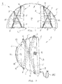
- a cabin or compartment C of an aircraft A is illustrated schematically bounded within a hemi-cylindrical fuselage F and by a floor structure L of the aircraft.
- Two partitions 1 according to an embodiment of the invention are installed to least partially divide the cabin or compartment C in a longitudinal direction of the fuselage F into sections.
- a central passage P is left open, e.g. as an aisle, for access between the sections.
- the partition 1 comprises a flexible membrane 2 which extends over substantially an entire areal expanse of the partition 1 and forms a flexible envelope 3 which defines or encloses a plurality of chambers 4 that are configured to be inflated or pressurized to stiffen the partition 1 in use.
- the membrane 2 or envelope 3 is formed from a relatively pliable sheet of synthetic material selected from the group consisting of nylon, polyester, polyethylene terephthalate, polyurethane, polyamide, and para-aramid synthetics, such as Kevlar TM .
- the plurality of chambers 4 defined or enclosed by the flexible membrane 2 or flexible envelope 3 are elongate and are arranged adjacent to one another or in a side-by-side relationship extending generally parallel over substantially the entire areal expanse of the partition.
- the partition 1 furthermore comprises reinforcing bands 5 which extend across and reinforce the envelope 3.
- the bands 5 are connected to, or integrated in, the flexible membrane 2, and comprise woven straps or belts adapted for tensile loading.
- these bands or tension elements 5 are desirably made of high performance fibres, such as dyneema, graphene, aramid, or carbon fibre. In this way, the bands 5 act to structurally stabilize the inflated or pressurized partition 1 in service.
- Upper and lower edge regions 6 of the partition are provided with one or more connecting elements 7 (e.g. anchor points, lugs or loops) at which the partition 1 can then be securely fastened to corresponding connecting members (not shown) on an internal structure of the fuselage F (e.g. seat rails in the floor structure L).
- each of the connecting elements or anchor points 7 is provided in a region of a respective reinforcing band 5 for structural stability.
- the partition 1 itself may be shaped or configured to suit the particular space or application, as required. That is, the two-dimensional shape or areal form of the partition 1 is essentially unlimited.
- a pressurized air supply AS typically available in the aircraft A is employed.
- the partition 1 includes at least one pressure relief valve 8 to release excess pressure in the event of an over-inflation or an over-pressurization of the partition.
- the degree of inflation or pressurization of the partition 1 required will vary with the ambient pressure within the cabin C. As the ambient pressure in the cabin C is subject to variation during the course of a flight (e.g.
- the partition 1 may include an electronic control unit 9 for monitoring the pressure in the partition 1 relative to the ambient pressure in the cabin C.
- the control unit 9 may operate to admit additional pressure from the air supply AS to the chambers 4 and/or to release air pressure from the chambers 4 via the relief valve(s) 8.
- the partition 1 can be seen to include a panel 10 which is at least partially defined by a frangible or breakable seam 11.
- the seam 11 is designed with a known rupture strength such that the seam 11 is configured to break or tear open in the event of a rapid decompression in the aircraft cabin C.
- the panel 11 is configured to pivot open in the manner of a flap or to be removed from the partition 1 completely to open an air-flow path through the partition 1.
- the partition 1 includes a foldable, collapsible, or re-tractable seat 12 mounted on a facing side 13 of the partition 1.
- the seat 12 is desirably mounted on, or supported by, reinforcing bands 5 connected to or integrated in the flexible membrane 2.
- the seat 12 may be configured as a cabin attendant seat typical in a commercial passenger aircraft, or as a troop seat typical in a military transport aircraft.
- the facing side 13 of the partition 1 may include pockets or satchels (not shown) integral with or attached to the membrane 2 for holding magazines or brochures.
- the facing side 13 of the partition 1 may include one or more display screen (not shown) for transmitting information or entertainment to passengers in the cabin C.
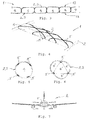
- FIG. 3 shows an example of how overlapping cords or cables may be arranged and integrated on or around each chamber 4 to provide structural reinforcement and strength the partition 1 in an inflated or pressurized state.
- Figs. 5 and 6 of the drawings illustrate further alternative configurations for the individual pressure chambers 4 in the partition 1. That is, the individual pressure chambers 4 may have a generally cylindrical form and may include reinforcing bands 5 integrated internally or within the membrane 2 or the envelope 3.
- Fig. 5 provides an example of a chamber 4 having a single inflatable cavity.
- Fig. 6 gives an example of a chamber 4 which is sub-divided by internal membranes into sub-chambers or sub-cavities 4'.
- each partition 1 clearly has a thickness (i.e. in a longitudinal direction of the fuselage F), in the inflated or pressurized state it will be appreciated that this thickness dimension is relatively small compared with the height and width dimensions of the partition 1 (i.e. transverse to the longitudinal direction).
- a further advantage of the partition 1 of the invention is that it may be readily demounted during service. That is, the air pressure may be released from the inflatable chambers 4 to collapse the partition 1 for demounting and/or folding the partition 1 out of the way. This may thereby provide space to enable large items, e.g. a stretcher, to be moved through the cabin C.
- the terms “comprise”, “comprising”, “include”, “including”, “contain”, “containing”, “have”, “having”, and any variations thereof, are intended to be understood in an inclusive (i.e. non-exclusive) sense, such that the process, method, device, apparatus or system described herein is not limited to those features or parts or elements or steps recited but may include other elements, features, parts or steps not expressly listed or inherent to such process, method, article, or apparatus.
- the terms “a” and “an” used herein are intended to be understood as meaning one or more unless explicitly stated otherwise.
- the terms “first”, “second”, “third”, etc. are used merely as labels, and are not intended to impose numerical requirements on or to establish a certain ranking of importance of their objects.
Landscapes
- Engineering & Computer Science (AREA)
- Aviation & Aerospace Engineering (AREA)
- Mechanical Engineering (AREA)
- Tents Or Canopies (AREA)
- Air Bags (AREA)
Abstract
Description
- The present invention relates to a partition for a cabin or compartment of an aircraft or spacecraft, and to an aircraft or spacecraft which includes such a partition.
- Partitions and class dividers are installed in the passenger compartments of commercial passenger aircraft to divide those passenger compartments into different sections or regions. The partitions typically comprise honeycomb sandwich panels which may be covered with a decor film and/or may include aluminium trim for protecting exposed edges of the panel. The lower portions of the partitions are attached to seat rails and the upper portions are attached to the PSC (under bin) or to the aircraft secondary structure (full height). Typically, the partitions have a thickness of 28mm, whereas their height depends on the ceiling and the hat-rack configuration of the aircraft. A distance to the cabin lining is usually a minimum of one inch (i.e. 25 mm), and the distance to OHSC-parts is usually about 40 mm. The partitions are often employed as class dividers (i.e. for dividing the passenger cabin or compartment of an aircraft into different class sections), but the partitions can also accommodate emergency equipment and/or electrical equipment.
- In aircraft and spacecraft design and construction, efforts are continually being made to enhance and improve production efficiency and costs, passenger safety, and to reduce overall weight while maintaining or improving component performance.
- It is therefore an object of the present invention to provide a new and improved partition for a cabin or compartment of an aircraft or spacecraft.
- In accordance with the present invention, a partition for a cabin is provided having the features recited in
claim 1. Preferred features are recited in the dependent claims. - According to one aspect, therefore, the invention provides a partition for a cabin or compartment of an aircraft or spacecraft, the partition comprising a flexible membrane which extends over substantially an entire areal expanse of the partition, wherein the flexible membrane defines or encloses at least one chamber which is configured to be inflated or pressurized in use to stiffen the partition.
- In this regard, it will be noted that the term "membrane" as used herein may be understood as a relatively pliable sheet of material. The membrane may comprise a synthetic film or foil, but may also comprise a woven or non-woven fabric or textile material, optionally coated by a sealing layer. The flexible membrane is preferably comprised of a synthetic material selected from the group consisting of polyester, nylon, polyethylene terephthalate, polyurethane, polyamide, and para-aramid synthetics, such as Kevlar™.
- In this way, the flexible membrane desirably forms a flexible envelope which extends over substantially the entire areal expanse of the partition. The flexible envelope is configured to be inflated or pressurized to stiffen the partition. The invention has the advantage that the flexible membrane and/or flexible envelope has the potential to provide the partition with a very low-mass or light-weight structure compared to conventional honeycomb aluminium partition structures or even fibre-reinforced polymer foam core sandwich structures. The more flexible and resilient nature of an inflated partition according to the invention also offers significantly improved behaviour in the event of a rapid decompression or crash with more advantageous head-impact criteria. The partition of the invention also provides branding and display opportunities.
- In order to inflate or pressurize the at least one chamber of the partition, the partition preferably employs a pressurized air supply system typically available in aircraft and spacecraft. That is, aircraft generally have access to a supply of pressurized air from the compressors of their jet turbines, which are also employed to pressurize the cabin space for flights at altitude.
- In a preferred embodiment, the flexible membrane or flexible envelope defines or encloses a plurality of chambers, each of which is configured to be inflated or pressurized to stiffen the partition in use. Preferably, the plurality of chambers is/are arranged adjacent or side-by-side one another. The inflatable chambers are typically elongate or long and desirably extend generally parallel to one another over substantially the entire areal expanse of the partition.
- In a preferred embodiment, the partition further comprises a plurality of reinforcing bands which extend across and reinforce the flexible membrane. The bands are preferably connected to or integrated in the flexible membrane, and the bands are preferably configured for tensile loading. In this regard, each of the bands may comprise any one or more of a strap, belt, cord, or cable. In this way, the partition may employ the "tensairity" principle by using pneumatic pressure (typically relatively low air pressure) to stabilize and to stiffen the partition against buckling. Thus, it may employ one or more inflated "air-beam" with bands (such as belts or cables) attached stiffeners, thereby gaining an advantage for low mass.
- In a preferred embodiment, the partition comprises connecting elements provided or arranged on a periphery of the partition for securely fastening the partition to complementary connecting members on a fuselage or internal structure of the aircraft or spacecraft. Each of the connecting elements is preferably provided in a region of a respective reinforcing band, for enhanced structural stability.
- In a preferred embodiment, the partition comprises one or more panel which includes, or is at least partially defined by, a frangible or breakable seam. This, the seam is designed to have a predetermined rupture strength. In this way, the seam may be configured to break or tear open in the event of a rapid decompression. In doing so, the panel may be configured either to pivot in the manner of a flap or to be completely extracted or removed from the partition, thereby to open an air-flow path through the partition.
- In a preferred embodiment, the partition comprises at least one pressure relief valve to release excess pressure in the inflated or pressurized chamber(s) in the event of an over-inflation or an over-pressurization of the partition.
- In a preferred embodiment, the partition further includes an electronic control unit mounted on a front and/or rear facing side of the partition.
- In a preferred embodiment, the partition includes a foldable, collapsible, or re-tractable seat mounted on a facing side of the partition. The seat is desirably mounted on or supported by a plurality of reinforcing bands connected to or integrated in the flexible membrane. In this way, the seat could be configured as a cabin attendant seat typical in a commercial passenger aircraft, or as a troop seat typical in a military transport aircraft.
- According to another aspect, the invention provides an aircraft or spacecraft having a cabin or compartment and one or more partition of the invention, especially according to any of the embodiments described above, which at least partially divides the cabin or compartment into sections.
- For a more complete understanding of the invention and the advantages thereof, exemplary embodiments of the invention are explained in more detail in the following description with reference to the accompanying drawing figures, in which like reference characters designate like parts and in which:
- Fig. 1
- is a sketch of an aircraft cabin or compartment having partitions according to an embodiment of the invention;
- Fig. 2
- is a sketch of a perspective view of a partition according to an embodiment of the invention;
- Fig. 3
- is a sketch of a cross-section view of a partition according to an embodiment of the invention;
- Fig. 4
- is a sketch in a partial perspective view of the partition in
Fig. 3 ; - Fig. 5
- is a sketch of a cross-section view of a partition according to another embodiment of the invention;
- Fig. 6
- is a sketch of a cross-section view of a partition according to a further embodiment; and
- Fig. 7
- shows an aircraft according to an embodiment of the invention.
- The accompanying drawings are included to provide a further understanding of the present invention and are incorporated in and constitute a part of this specification. The drawings illustrate particular embodiments of the invention and together with the description serve to explain the principles of the invention. Other embodiments of the invention and many of the attendant advantages of the invention will be readily appreciated as they become better understood with reference to the following detailed description.
- It will be appreciated that common and well understood elements that may be useful or necessary in a commercially feasible embodiment are not necessarily depicted in order to facilitate a more abstracted view of the embodiments. The elements of the drawings are not necessarily illustrated to scale relative to each other. It will further be appreciated that certain actions and/or steps in an embodiment of a method may be described or depicted in a particular order of occurrences while those skilled in the art will understand that such specificity with respect to sequence is not necessarily required. It will also be understood that the terms and expressions used in the present specification have the ordinary meaning as it accorded to such terms and expressions with respect to their corresponding respective areas of inquiry and study, except where specific meanings have otherwise been set forth herein.
- With reference firstly to
Fig. 1 of the drawings, a cabin or compartment C of an aircraft A is illustrated schematically bounded within a hemi-cylindrical fuselage F and by a floor structure L of the aircraft. Twopartitions 1 according to an embodiment of the invention are installed to least partially divide the cabin or compartment C in a longitudinal direction of the fuselage F into sections. A central passage P is left open, e.g. as an aisle, for access between the sections. - Referring also to drawing
Fig. 2 , details of eachpartition 1 according to a preferred embodiment of the invention will be explained. Thepartition 1 comprises aflexible membrane 2 which extends over substantially an entire areal expanse of thepartition 1 and forms aflexible envelope 3 which defines or encloses a plurality ofchambers 4 that are configured to be inflated or pressurized to stiffen thepartition 1 in use. Themembrane 2 orenvelope 3 is formed from a relatively pliable sheet of synthetic material selected from the group consisting of nylon, polyester, polyethylene terephthalate, polyurethane, polyamide, and para-aramid synthetics, such as Kevlar™. - As can be seen in
Fig. 2 , the plurality ofchambers 4 defined or enclosed by theflexible membrane 2 orflexible envelope 3 are elongate and are arranged adjacent to one another or in a side-by-side relationship extending generally parallel over substantially the entire areal expanse of the partition. Thepartition 1 furthermore comprises reinforcingbands 5 which extend across and reinforce theenvelope 3. Thebands 5 are connected to, or integrated in, theflexible membrane 2, and comprise woven straps or belts adapted for tensile loading. Thus, these bands ortension elements 5 are desirably made of high performance fibres, such as dyneema, graphene, aramid, or carbon fibre. In this way, thebands 5 act to structurally stabilize the inflated orpressurized partition 1 in service. Upper andlower edge regions 6 of the partition are provided with one or more connecting elements 7 (e.g. anchor points, lugs or loops) at which thepartition 1 can then be securely fastened to corresponding connecting members (not shown) on an internal structure of the fuselage F (e.g. seat rails in the floor structure L). Preferably, each of the connecting elements or anchor points 7 is provided in a region of a respective reinforcingband 5 for structural stability. - The
partition 1 itself may be shaped or configured to suit the particular space or application, as required. That is, the two-dimensional shape or areal form of thepartition 1 is essentially unlimited. In order to inflate or pressurize thechambers 4 of thepartition 1, a pressurized air supply AS typically available in the aircraft A is employed. Also, thepartition 1 includes at least one pressure relief valve 8 to release excess pressure in the event of an over-inflation or an over-pressurization of the partition. To this end, it will be noted that the degree of inflation or pressurization of thepartition 1 required will vary with the ambient pressure within the cabin C. As the ambient pressure in the cabin C is subject to variation during the course of a flight (e.g. with varying altitude), thepartition 1 may include anelectronic control unit 9 for monitoring the pressure in thepartition 1 relative to the ambient pressure in the cabin C. In this way, thecontrol unit 9 may operate to admit additional pressure from the air supply AS to thechambers 4 and/or to release air pressure from thechambers 4 via the relief valve(s) 8. - Referring further to
Fig. 2 , thepartition 1 can be seen to include apanel 10 which is at least partially defined by a frangible or breakable seam 11. The seam 11 is designed with a known rupture strength such that the seam 11 is configured to break or tear open in the event of a rapid decompression in the aircraft cabin C. Thus, as the seam 11 ruptures, the panel 11 is configured to pivot open in the manner of a flap or to be removed from thepartition 1 completely to open an air-flow path through thepartition 1. - The only apparent difference between the
partitions 1 shown inFig. 1 and Fig. 2 is that, in the embodiment ofFig. 1 theelongate air chambers 4 of eachpartition 1 extend generally horizontally, whereas in the embodiment ofFig. 2 theair chambers 4 of eachpartition 1 extend generally vertically. It will also be noted inFig. 1 that thepartition 1 includes a foldable, collapsible, orre-tractable seat 12 mounted on a facingside 13 of thepartition 1. Theseat 12 is desirably mounted on, or supported by, reinforcingbands 5 connected to or integrated in theflexible membrane 2. Theseat 12 may be configured as a cabin attendant seat typical in a commercial passenger aircraft, or as a troop seat typical in a military transport aircraft. - In addition, or as an alternative, to the
seat 12, the facingside 13 of thepartition 1 may include pockets or satchels (not shown) integral with or attached to themembrane 2 for holding magazines or brochures. Furthermore, the facingside 13 of thepartition 1 may include one or more display screen (not shown) for transmitting information or entertainment to passengers in the cabin C. - With reference now to
Figs. 3 and 4 of the drawings, examples of the configuration ofindividual pressure chambers 4 in thepartition 1 are illustrated. The generally rectangular cross-section shown inFig. 3 could correspond to the plurality of vertically extendingchambers 4 in thepartition 1 ofFig. 2 .Fig. 4 shows an example of how overlapping cords or cables may be arranged and integrated on or around eachchamber 4 to provide structural reinforcement and strength thepartition 1 in an inflated or pressurized state. -
Figs. 5 and 6 of the drawings illustrate further alternative configurations for theindividual pressure chambers 4 in thepartition 1. That is, theindividual pressure chambers 4 may have a generally cylindrical form and may include reinforcingbands 5 integrated internally or within themembrane 2 or theenvelope 3.Fig. 5 provides an example of achamber 4 having a single inflatable cavity.Fig. 6 , on the other hand, gives an example of achamber 4 which is sub-divided by internal membranes into sub-chambers or sub-cavities 4'. - Although each
partition 1 clearly has a thickness (i.e. in a longitudinal direction of the fuselage F), in the inflated or pressurized state it will be appreciated that this thickness dimension is relatively small compared with the height and width dimensions of the partition 1 (i.e. transverse to the longitudinal direction). - A further advantage of the
partition 1 of the invention is that it may be readily demounted during service. That is, the air pressure may be released from theinflatable chambers 4 to collapse thepartition 1 for demounting and/or folding thepartition 1 out of the way. This may thereby provide space to enable large items, e.g. a stretcher, to be moved through the cabin C. - Although specific embodiments of the invention have been illustrated and described herein, it will be appreciated by those of ordinary skill in the art that a variety of alternate and/or equivalent implementations exist. It should be appreciated that the exemplary embodiment or exemplary embodiments are only examples, and are not intended to limit the scope, applicability, or configuration in any way. Rather, the foregoing summary and detailed description will provide those skilled in the art with a convenient road map for implementing at least one exemplary embodiment, it being understood that various changes may be made in the function and arrangement of elements described in an exemplary embodiment without departing from the scope as set forth in the appended claims and their legal equivalents. Generally, this application is intended to cover any adaptations or variations of the specific embodiments discussed herein.
- In this document, the terms "comprise", "comprising", "include", "including", "contain", "containing", "have", "having", and any variations thereof, are intended to be understood in an inclusive (i.e. non-exclusive) sense, such that the process, method, device, apparatus or system described herein is not limited to those features or parts or elements or steps recited but may include other elements, features, parts or steps not expressly listed or inherent to such process, method, article, or apparatus. Furthermore, the terms "a" and "an" used herein are intended to be understood as meaning one or more unless explicitly stated otherwise. Moreover, the terms "first", "second", "third", etc. are used merely as labels, and are not intended to impose numerical requirements on or to establish a certain ranking of importance of their objects.
-
- 1
- partition
- 2
- membrane
- 3
- envelope
- 4
- chamber
- 5
- reinforcing band or tension element
- 6
- edge regions of the partition
- 7
- connecting element or anchor point
- 8
- pressure relief valve
- 9
- control unit
- 10
- panel
- 11
- frangible or breakable seam
- 12
- seat
- 13
- facing side of the partition
- A
- aircraft
- F
- fuselage
- C
- cabin
- L
- floor structure
- P
- central passage
- AS
- pressurized air supply
Claims (13)
- A partition (1) for a cabin or compartment of an aircraft or spacecraft, comprising a flexible membrane (2) which extends over substantially an entire areal expanse of the partition (1), wherein the flexible membrane (2) defines or encloses at least one chamber (4) which is configured to be inflated or pressurized to stiffen the partition (1).
- A partition (1) according to claim 1, wherein the flexible membrane (2) forms a flexible envelope (3) that extends over substantially the entire areal expanse of the partition (1), wherein the flexible envelope (3) is configured to be inflated or pressurized to stiffen the partition (1).
- A partition (1) according to claim 1 or claim 2, wherein the flexible membrane (2) defines multiple chambers (4), each of which is designed to be inflated or pressurized to stiffen the partition (1).
- A partition (1) according to claim 3, wherein the multiple chambers (4) are arranged adjacent one another or side-by-side, wherein the chambers (4) are preferably elongate and preferably extend substantially parallel to one another over substantially the entire areal expanse of the partition (1).
- A partition (1) according to any one of the preceding claims, further comprising a plurality of reinforcing bands (5) which extend across and reinforce the flexible membrane (2), wherein the bands (5) are preferably connected to or integrated in the flexible membrane (2), and wherein the bands (5) are preferably configured for tensile loading.
- A partition (1) according to claim 5, wherein the bands (5) comprise any one or more of: straps, belts, cords, and cables.
- A partition (1) according to any one of the preceding claims, comprising connecting elements (7) provided on a periphery of the partition (1) for securely fastening the partition (1) to complementary connecting members on a fuselage of the aircraft or spacecraft, each of the connecting elements (7) preferably being provided in a region of a respective reinforcing band (5).
- A partition (1) according to any one of the preceding claims, further comprising one or more panel (10) which includes a frangible or breakable seam (11) configured to open in the event of a rapid decompression to open an air-flow path through the partition (1).
- A partition (1) according to any one of the preceding claims, further comprising at least one pressure relief valve (8) to release excess pressure in the at least one chamber (4) in the event of an over-inflation or over-pressurization of the partition.
- A partition (1) according to any one of the preceding claims, further including a control unit (9) mounted on a facing side (11) of the partition (1) for regulating pressure in the partition (1).
- A partition (1) according to any one of the preceding claims, further comprising a foldable, collapsible, or re-tractable seat (12) mounted on a facing side (13) of the partition (1); wherein the seat (12) is desirably mounted on or supported by reinforcing bands (5) connected to or integrated in the flexible membrane (2).
- A partition (1) according to any one of the preceding claims, wherein the flexible membrane (2) is comprised of a synthetic material selected from a group consisting of: nylon, polyester, polyethylene terephthalate, polyurethane, polyamide, and para-aramid synthetics, such as Kevlar™.
- An aircraft or spacecraft having a cabin or compartment (C) and one or more partition (1) according to any one of the preceding claims which at least partially divides the cabin or compartment (C) into sections.
Priority Applications (1)
| Application Number | Priority Date | Filing Date | Title |
|---|---|---|---|
| EP16180294.7A EP3272643B1 (en) | 2016-07-20 | 2016-07-20 | Aircraft or spacecraft passenger cabin partition |
Applications Claiming Priority (1)
| Application Number | Priority Date | Filing Date | Title |
|---|---|---|---|
| EP16180294.7A EP3272643B1 (en) | 2016-07-20 | 2016-07-20 | Aircraft or spacecraft passenger cabin partition |
Publications (2)
| Publication Number | Publication Date |
|---|---|
| EP3272643A1 true EP3272643A1 (en) | 2018-01-24 |
| EP3272643B1 EP3272643B1 (en) | 2021-11-10 |
Family
ID=56507420
Family Applications (1)
| Application Number | Title | Priority Date | Filing Date |
|---|---|---|---|
| EP16180294.7A Active EP3272643B1 (en) | 2016-07-20 | 2016-07-20 | Aircraft or spacecraft passenger cabin partition |
Country Status (1)
| Country | Link |
|---|---|
| EP (1) | EP3272643B1 (en) |
Cited By (5)
| Publication number | Priority date | Publication date | Assignee | Title |
|---|---|---|---|---|
| DE102018120621A1 (en) * | 2018-08-23 | 2020-02-27 | Airbus Operations Gmbh | Foldable separation device and method for installing a foldable separation device in a passenger cabin |
| EP3919383A1 (en) * | 2020-06-04 | 2021-12-08 | Koninklijke Fabriek Inventum B.V. | Inflatable isolation walls for aircraft cabins |
| EP4005924A1 (en) * | 2020-11-30 | 2022-06-01 | Bucher Leichtbau AG | Lightweight component to be set up vertically for a cantilevered load receiver |
| EP4108569A1 (en) | 2021-06-25 | 2022-12-28 | Airbus Operations GmbH | Inflatable suspended ceiling for a vehicle compartment, in particular for a passenger cabin of an aircraft |
| EP4112468A1 (en) | 2021-07-02 | 2023-01-04 | Airbus Operations GmbH | Inflatable separation area for a vehicle interior |
Citations (6)
| Publication number | Priority date | Publication date | Assignee | Title |
|---|---|---|---|---|
| US4899962A (en) * | 1988-01-27 | 1990-02-13 | Messerschmitt-Boelkow-Blohm Gmbh | Portable fire retardant separation wall especially for aircraft |
| DE3844080A1 (en) * | 1988-12-28 | 1990-07-12 | Messerschmitt Boelkow Blohm | Pressure wall for an aircraft fuselage |
| US5062589A (en) * | 1989-02-28 | 1991-11-05 | Dornier Luftfahrt Gmbh | Fiber reinforced pressure bulkhead with integrated frame |
| US20130020369A1 (en) * | 2011-07-22 | 2013-01-24 | Dassault Aviation | Frangible hinge mechanism for a platform partition, associated partition, assembly and method |
| EP2942268A1 (en) * | 2014-05-09 | 2015-11-11 | Airbus Operations GmbH | Aircraft having a self-erecting partition element in a compartment inside the fuselage |
| WO2016091907A1 (en) * | 2014-12-09 | 2016-06-16 | Airbus Operations Gmbh | Flight attendant seat, arrangement having a flight attendant seat, and aircraft area |
Family Cites Families (1)
| Publication number | Priority date | Publication date | Assignee | Title |
|---|---|---|---|---|
| EP1688067B1 (en) * | 2001-07-10 | 2008-11-05 | CHAFFEE, Robert B. | Configurable inflatable support devices |
-
2016
- 2016-07-20 EP EP16180294.7A patent/EP3272643B1/en active Active
Patent Citations (6)
| Publication number | Priority date | Publication date | Assignee | Title |
|---|---|---|---|---|
| US4899962A (en) * | 1988-01-27 | 1990-02-13 | Messerschmitt-Boelkow-Blohm Gmbh | Portable fire retardant separation wall especially for aircraft |
| DE3844080A1 (en) * | 1988-12-28 | 1990-07-12 | Messerschmitt Boelkow Blohm | Pressure wall for an aircraft fuselage |
| US5062589A (en) * | 1989-02-28 | 1991-11-05 | Dornier Luftfahrt Gmbh | Fiber reinforced pressure bulkhead with integrated frame |
| US20130020369A1 (en) * | 2011-07-22 | 2013-01-24 | Dassault Aviation | Frangible hinge mechanism for a platform partition, associated partition, assembly and method |
| EP2942268A1 (en) * | 2014-05-09 | 2015-11-11 | Airbus Operations GmbH | Aircraft having a self-erecting partition element in a compartment inside the fuselage |
| WO2016091907A1 (en) * | 2014-12-09 | 2016-06-16 | Airbus Operations Gmbh | Flight attendant seat, arrangement having a flight attendant seat, and aircraft area |
Cited By (8)
| Publication number | Priority date | Publication date | Assignee | Title |
|---|---|---|---|---|
| DE102018120621A1 (en) * | 2018-08-23 | 2020-02-27 | Airbus Operations Gmbh | Foldable separation device and method for installing a foldable separation device in a passenger cabin |
| EP3919383A1 (en) * | 2020-06-04 | 2021-12-08 | Koninklijke Fabriek Inventum B.V. | Inflatable isolation walls for aircraft cabins |
| US11691733B2 (en) | 2020-06-04 | 2023-07-04 | B/E Aerospac, Inc. | Inflatable isolation walls for aircraft cabins |
| EP4005924A1 (en) * | 2020-11-30 | 2022-06-01 | Bucher Leichtbau AG | Lightweight component to be set up vertically for a cantilevered load receiver |
| EP4108569A1 (en) | 2021-06-25 | 2022-12-28 | Airbus Operations GmbH | Inflatable suspended ceiling for a vehicle compartment, in particular for a passenger cabin of an aircraft |
| US12054236B2 (en) | 2021-06-25 | 2024-08-06 | Airbus Operations Gmbh | Inflatable suspended ceiling for a vehicle compartment, in particular for a passenger cabin of an aircraft |
| EP4112468A1 (en) | 2021-07-02 | 2023-01-04 | Airbus Operations GmbH | Inflatable separation area for a vehicle interior |
| US12240608B2 (en) | 2021-07-02 | 2025-03-04 | Airbus Operations Gmbh | Inflatable separating region for a vehicle interior |
Also Published As
| Publication number | Publication date |
|---|---|
| EP3272643B1 (en) | 2021-11-10 |
Similar Documents
| Publication | Publication Date | Title |
|---|---|---|
| EP3272643B1 (en) | Aircraft or spacecraft passenger cabin partition | |
| US4728059A (en) | Pressurized wall in aircraft | |
| EP1911674A2 (en) | Fuselage mounted evacuation slide system | |
| US4899962A (en) | Portable fire retardant separation wall especially for aircraft | |
| CN107826258B (en) | Inflatable evacuation system with canopy support | |
| US9522747B2 (en) | Inflatable deceleration apparatus | |
| US7185851B2 (en) | Inflatable aerodynamic wing and method | |
| US5845879A (en) | Inflatable conformable fuel tank | |
| US6092272A (en) | Modified container using inner bag | |
| WO1998002367A1 (en) | High pressure air cushion for computer | |
| DE60307627T2 (en) | WATER VEHICLE WITH FAST DEFLECTABLE, HIGH PRESSURE INFLATABLE PLATES | |
| EP2032431A2 (en) | Pressure bulkhead for an aerospace fuselage | |
| US20180334257A1 (en) | Off-wing slide raft | |
| EP1410986A2 (en) | Breakaway lacing for emergency evacuation slide | |
| EP3296210B1 (en) | Arched inflatable structure for evacuation slide systems | |
| US11434013B2 (en) | Continuously tensioned truss strap | |
| US20190112059A1 (en) | Evacuation slide with aspirator retention strap | |
| US8864080B2 (en) | Expendable aerial delivery system | |
| EP4026772B1 (en) | Inflatable partition | |
| US6019316A (en) | Device for suspending an aircraft tank | |
| US8366052B1 (en) | Detachable inflation system for air vehicles | |
| US10752329B2 (en) | Aircraft fuselage frame equipped with airbag and riser duct closure cover | |
| US20170001703A1 (en) | Aircraft external part with inflatable panels | |
| Coatta et al. | Development and testing of an 8m isotensoid supersonic inflatable aerodynamic decelerator (siad) | |
| US20220089290A1 (en) | Evacuation slide having drop stitch inflatable structure |
Legal Events
| Date | Code | Title | Description |
|---|---|---|---|
| PUAI | Public reference made under article 153(3) epc to a published international application that has entered the european phase |
Free format text: ORIGINAL CODE: 0009012 |
|
| STAA | Information on the status of an ep patent application or granted ep patent |
Free format text: STATUS: THE APPLICATION HAS BEEN PUBLISHED |
|
| AK | Designated contracting states |
Kind code of ref document: A1 Designated state(s): AL AT BE BG CH CY CZ DE DK EE ES FI FR GB GR HR HU IE IS IT LI LT LU LV MC MK MT NL NO PL PT RO RS SE SI SK SM TR |
|
| AX | Request for extension of the european patent |
Extension state: BA ME |
|
| STAA | Information on the status of an ep patent application or granted ep patent |
Free format text: STATUS: REQUEST FOR EXAMINATION WAS MADE |
|
| 17P | Request for examination filed |
Effective date: 20180305 |
|
| RBV | Designated contracting states (corrected) |
Designated state(s): AL AT BE BG CH CY CZ DE DK EE ES FI FR GB GR HR HU IE IS IT LI LT LU LV MC MK MT NL NO PL PT RO RS SE SI SK SM TR |
|
| STAA | Information on the status of an ep patent application or granted ep patent |
Free format text: STATUS: EXAMINATION IS IN PROGRESS |
|
| 17Q | First examination report despatched |
Effective date: 20200206 |
|
| GRAP | Despatch of communication of intention to grant a patent |
Free format text: ORIGINAL CODE: EPIDOSNIGR1 |
|
| STAA | Information on the status of an ep patent application or granted ep patent |
Free format text: STATUS: GRANT OF PATENT IS INTENDED |
|
| INTG | Intention to grant announced |
Effective date: 20210705 |
|
| GRAS | Grant fee paid |
Free format text: ORIGINAL CODE: EPIDOSNIGR3 |
|
| GRAA | (expected) grant |
Free format text: ORIGINAL CODE: 0009210 |
|
| STAA | Information on the status of an ep patent application or granted ep patent |
Free format text: STATUS: THE PATENT HAS BEEN GRANTED |
|
| AK | Designated contracting states |
Kind code of ref document: B1 Designated state(s): AL AT BE BG CH CY CZ DE DK EE ES FI FR GB GR HR HU IE IS IT LI LT LU LV MC MK MT NL NO PL PT RO RS SE SI SK SM TR |
|
| REG | Reference to a national code |
Ref country code: GB Ref legal event code: FG4D |
|
| REG | Reference to a national code |
Ref country code: AT Ref legal event code: REF Ref document number: 1445867 Country of ref document: AT Kind code of ref document: T Effective date: 20211115 Ref country code: CH Ref legal event code: EP |
|
| REG | Reference to a national code |
Ref country code: DE Ref legal event code: R096 Ref document number: 602016065932 Country of ref document: DE |
|
| REG | Reference to a national code |
Ref country code: IE Ref legal event code: FG4D |
|
| REG | Reference to a national code |
Ref country code: LT Ref legal event code: MG9D |
|
| REG | Reference to a national code |
Ref country code: NL Ref legal event code: MP Effective date: 20211110 |
|
| REG | Reference to a national code |
Ref country code: AT Ref legal event code: MK05 Ref document number: 1445867 Country of ref document: AT Kind code of ref document: T Effective date: 20211110 |
|
| PG25 | Lapsed in a contracting state [announced via postgrant information from national office to epo] |
Ref country code: RS Free format text: LAPSE BECAUSE OF FAILURE TO SUBMIT A TRANSLATION OF THE DESCRIPTION OR TO PAY THE FEE WITHIN THE PRESCRIBED TIME-LIMIT Effective date: 20211110 Ref country code: LT Free format text: LAPSE BECAUSE OF FAILURE TO SUBMIT A TRANSLATION OF THE DESCRIPTION OR TO PAY THE FEE WITHIN THE PRESCRIBED TIME-LIMIT Effective date: 20211110 Ref country code: FI Free format text: LAPSE BECAUSE OF FAILURE TO SUBMIT A TRANSLATION OF THE DESCRIPTION OR TO PAY THE FEE WITHIN THE PRESCRIBED TIME-LIMIT Effective date: 20211110 Ref country code: BG Free format text: LAPSE BECAUSE OF FAILURE TO SUBMIT A TRANSLATION OF THE DESCRIPTION OR TO PAY THE FEE WITHIN THE PRESCRIBED TIME-LIMIT Effective date: 20220210 Ref country code: AT Free format text: LAPSE BECAUSE OF FAILURE TO SUBMIT A TRANSLATION OF THE DESCRIPTION OR TO PAY THE FEE WITHIN THE PRESCRIBED TIME-LIMIT Effective date: 20211110 |
|
| PG25 | Lapsed in a contracting state [announced via postgrant information from national office to epo] |
Ref country code: IS Free format text: LAPSE BECAUSE OF FAILURE TO SUBMIT A TRANSLATION OF THE DESCRIPTION OR TO PAY THE FEE WITHIN THE PRESCRIBED TIME-LIMIT Effective date: 20220310 Ref country code: SE Free format text: LAPSE BECAUSE OF FAILURE TO SUBMIT A TRANSLATION OF THE DESCRIPTION OR TO PAY THE FEE WITHIN THE PRESCRIBED TIME-LIMIT Effective date: 20211110 Ref country code: PT Free format text: LAPSE BECAUSE OF FAILURE TO SUBMIT A TRANSLATION OF THE DESCRIPTION OR TO PAY THE FEE WITHIN THE PRESCRIBED TIME-LIMIT Effective date: 20220310 Ref country code: PL Free format text: LAPSE BECAUSE OF FAILURE TO SUBMIT A TRANSLATION OF THE DESCRIPTION OR TO PAY THE FEE WITHIN THE PRESCRIBED TIME-LIMIT Effective date: 20211110 Ref country code: NO Free format text: LAPSE BECAUSE OF FAILURE TO SUBMIT A TRANSLATION OF THE DESCRIPTION OR TO PAY THE FEE WITHIN THE PRESCRIBED TIME-LIMIT Effective date: 20220210 Ref country code: NL Free format text: LAPSE BECAUSE OF FAILURE TO SUBMIT A TRANSLATION OF THE DESCRIPTION OR TO PAY THE FEE WITHIN THE PRESCRIBED TIME-LIMIT Effective date: 20211110 Ref country code: LV Free format text: LAPSE BECAUSE OF FAILURE TO SUBMIT A TRANSLATION OF THE DESCRIPTION OR TO PAY THE FEE WITHIN THE PRESCRIBED TIME-LIMIT Effective date: 20211110 Ref country code: HR Free format text: LAPSE BECAUSE OF FAILURE TO SUBMIT A TRANSLATION OF THE DESCRIPTION OR TO PAY THE FEE WITHIN THE PRESCRIBED TIME-LIMIT Effective date: 20211110 Ref country code: GR Free format text: LAPSE BECAUSE OF FAILURE TO SUBMIT A TRANSLATION OF THE DESCRIPTION OR TO PAY THE FEE WITHIN THE PRESCRIBED TIME-LIMIT Effective date: 20220211 Ref country code: ES Free format text: LAPSE BECAUSE OF FAILURE TO SUBMIT A TRANSLATION OF THE DESCRIPTION OR TO PAY THE FEE WITHIN THE PRESCRIBED TIME-LIMIT Effective date: 20211110 |
|
| PG25 | Lapsed in a contracting state [announced via postgrant information from national office to epo] |
Ref country code: SM Free format text: LAPSE BECAUSE OF FAILURE TO SUBMIT A TRANSLATION OF THE DESCRIPTION OR TO PAY THE FEE WITHIN THE PRESCRIBED TIME-LIMIT Effective date: 20211110 Ref country code: SK Free format text: LAPSE BECAUSE OF FAILURE TO SUBMIT A TRANSLATION OF THE DESCRIPTION OR TO PAY THE FEE WITHIN THE PRESCRIBED TIME-LIMIT Effective date: 20211110 Ref country code: RO Free format text: LAPSE BECAUSE OF FAILURE TO SUBMIT A TRANSLATION OF THE DESCRIPTION OR TO PAY THE FEE WITHIN THE PRESCRIBED TIME-LIMIT Effective date: 20211110 Ref country code: EE Free format text: LAPSE BECAUSE OF FAILURE TO SUBMIT A TRANSLATION OF THE DESCRIPTION OR TO PAY THE FEE WITHIN THE PRESCRIBED TIME-LIMIT Effective date: 20211110 Ref country code: DK Free format text: LAPSE BECAUSE OF FAILURE TO SUBMIT A TRANSLATION OF THE DESCRIPTION OR TO PAY THE FEE WITHIN THE PRESCRIBED TIME-LIMIT Effective date: 20211110 Ref country code: CZ Free format text: LAPSE BECAUSE OF FAILURE TO SUBMIT A TRANSLATION OF THE DESCRIPTION OR TO PAY THE FEE WITHIN THE PRESCRIBED TIME-LIMIT Effective date: 20211110 |
|
| REG | Reference to a national code |
Ref country code: DE Ref legal event code: R097 Ref document number: 602016065932 Country of ref document: DE |
|
| PLBE | No opposition filed within time limit |
Free format text: ORIGINAL CODE: 0009261 |
|
| STAA | Information on the status of an ep patent application or granted ep patent |
Free format text: STATUS: NO OPPOSITION FILED WITHIN TIME LIMIT |
|
| 26N | No opposition filed |
Effective date: 20220811 |
|
| PG25 | Lapsed in a contracting state [announced via postgrant information from national office to epo] |
Ref country code: AL Free format text: LAPSE BECAUSE OF FAILURE TO SUBMIT A TRANSLATION OF THE DESCRIPTION OR TO PAY THE FEE WITHIN THE PRESCRIBED TIME-LIMIT Effective date: 20211110 |
|
| PG25 | Lapsed in a contracting state [announced via postgrant information from national office to epo] |
Ref country code: SI Free format text: LAPSE BECAUSE OF FAILURE TO SUBMIT A TRANSLATION OF THE DESCRIPTION OR TO PAY THE FEE WITHIN THE PRESCRIBED TIME-LIMIT Effective date: 20211110 |
|
| PG25 | Lapsed in a contracting state [announced via postgrant information from national office to epo] |
Ref country code: MC Free format text: LAPSE BECAUSE OF FAILURE TO SUBMIT A TRANSLATION OF THE DESCRIPTION OR TO PAY THE FEE WITHIN THE PRESCRIBED TIME-LIMIT Effective date: 20211110 |
|
| REG | Reference to a national code |
Ref country code: CH Ref legal event code: PL |
|
| REG | Reference to a national code |
Ref country code: BE Ref legal event code: MM Effective date: 20220731 |
|
| PG25 | Lapsed in a contracting state [announced via postgrant information from national office to epo] |
Ref country code: LU Free format text: LAPSE BECAUSE OF NON-PAYMENT OF DUE FEES Effective date: 20220720 Ref country code: LI Free format text: LAPSE BECAUSE OF NON-PAYMENT OF DUE FEES Effective date: 20220731 Ref country code: CH Free format text: LAPSE BECAUSE OF NON-PAYMENT OF DUE FEES Effective date: 20220731 |
|
| PG25 | Lapsed in a contracting state [announced via postgrant information from national office to epo] |
Ref country code: IT Free format text: LAPSE BECAUSE OF FAILURE TO SUBMIT A TRANSLATION OF THE DESCRIPTION OR TO PAY THE FEE WITHIN THE PRESCRIBED TIME-LIMIT Effective date: 20211110 Ref country code: BE Free format text: LAPSE BECAUSE OF NON-PAYMENT OF DUE FEES Effective date: 20220731 |
|
| PG25 | Lapsed in a contracting state [announced via postgrant information from national office to epo] |
Ref country code: IE Free format text: LAPSE BECAUSE OF NON-PAYMENT OF DUE FEES Effective date: 20220720 |
|
| PG25 | Lapsed in a contracting state [announced via postgrant information from national office to epo] |
Ref country code: HU Free format text: LAPSE BECAUSE OF FAILURE TO SUBMIT A TRANSLATION OF THE DESCRIPTION OR TO PAY THE FEE WITHIN THE PRESCRIBED TIME-LIMIT; INVALID AB INITIO Effective date: 20160720 |
|
| PG25 | Lapsed in a contracting state [announced via postgrant information from national office to epo] |
Ref country code: MK Free format text: LAPSE BECAUSE OF FAILURE TO SUBMIT A TRANSLATION OF THE DESCRIPTION OR TO PAY THE FEE WITHIN THE PRESCRIBED TIME-LIMIT Effective date: 20211110 Ref country code: CY Free format text: LAPSE BECAUSE OF FAILURE TO SUBMIT A TRANSLATION OF THE DESCRIPTION OR TO PAY THE FEE WITHIN THE PRESCRIBED TIME-LIMIT Effective date: 20211110 |
|
| PG25 | Lapsed in a contracting state [announced via postgrant information from national office to epo] |
Ref country code: TR Free format text: LAPSE BECAUSE OF FAILURE TO SUBMIT A TRANSLATION OF THE DESCRIPTION OR TO PAY THE FEE WITHIN THE PRESCRIBED TIME-LIMIT Effective date: 20211110 |
|
| PG25 | Lapsed in a contracting state [announced via postgrant information from national office to epo] |
Ref country code: MT Free format text: LAPSE BECAUSE OF FAILURE TO SUBMIT A TRANSLATION OF THE DESCRIPTION OR TO PAY THE FEE WITHIN THE PRESCRIBED TIME-LIMIT Effective date: 20211110 |
|
| PGFP | Annual fee paid to national office [announced via postgrant information from national office to epo] |
Ref country code: GB Payment date: 20240725 Year of fee payment: 9 |
|
| PGFP | Annual fee paid to national office [announced via postgrant information from national office to epo] |
Ref country code: DE Payment date: 20250722 Year of fee payment: 10 |
|
| PGFP | Annual fee paid to national office [announced via postgrant information from national office to epo] |
Ref country code: FR Payment date: 20250725 Year of fee payment: 10 |
|
| GBPC | Gb: european patent ceased through non-payment of renewal fee |
Effective date: 20250720 |
|
| PG25 | Lapsed in a contracting state [announced via postgrant information from national office to epo] |
Ref country code: GB Free format text: LAPSE BECAUSE OF NON-PAYMENT OF DUE FEES Effective date: 20250720 |