EP3277107B1 - Procédé pour produire un premier sous-ensemble d'un article à fumer à chauffage sans combustion, présentant un corps formant tige et une cavité montée dessus, sous-ensemble et article à fumer à chauffage sans combustion - Google Patents
Procédé pour produire un premier sous-ensemble d'un article à fumer à chauffage sans combustion, présentant un corps formant tige et une cavité montée dessus, sous-ensemble et article à fumer à chauffage sans combustion Download PDFInfo
- Publication number
- EP3277107B1 EP3277107B1 EP16707098.6A EP16707098A EP3277107B1 EP 3277107 B1 EP3277107 B1 EP 3277107B1 EP 16707098 A EP16707098 A EP 16707098A EP 3277107 B1 EP3277107 B1 EP 3277107B1
- Authority
- EP
- European Patent Office
- Prior art keywords
- rod
- tubular body
- subunit
- shaped body
- cavity
- Prior art date
- Legal status (The legal status is an assumption and is not a legal conclusion. Google has not performed a legal analysis and makes no representation as to the accuracy of the status listed.)
- Active
Links
Images

Classifications
-
- A—HUMAN NECESSITIES
- A24—TOBACCO; CIGARS; CIGARETTES; SIMULATED SMOKING DEVICES; SMOKERS' REQUISITES
- A24C—MACHINES FOR MAKING CIGARS OR CIGARETTES
- A24C5/00—Making cigarettes; Making tipping materials for, or attaching filters or mouthpieces to, cigars or cigarettes
-
- A—HUMAN NECESSITIES
- A24—TOBACCO; CIGARS; CIGARETTES; SIMULATED SMOKING DEVICES; SMOKERS' REQUISITES
- A24D—CIGARS; CIGARETTES; TOBACCO SMOKE FILTERS; MOUTHPIECES OF CIGARS OR CIGARETTES; MANUFACTURE OF TOBACCO SMOKE FILTERS OR MOUTHPIECES
- A24D1/00—Cigars; Cigarettes
- A24D1/22—Cigarettes with integrated combustible heat sources, e.g. with carbonaceous heat sources
Definitions
- the present invention relates to a method for producing a first subunit of a HNB smoking article with a rod body and a cavity arranged thereon with the features of the preamble of claim 1, a subunit with the features of the preamble of claim 9 and an HNB smoking article according to claim 14 ,
- HNB smoking articles are based on a fundamentally different principle of releasing essential constituents of tobacco than conventional smoking articles, in which the constituents are released by burning off the tobacco.
- HNB heat not burn
- the constituents of the tobacco are released by flowing the tobacco through hot gases and / or heating the tobacco, so that the smoke constituents formerly forcibly released upon combustion of the tobacco are at least substantially reduced or even completely avoided.
- a heat source is provided in the HNB smoking article, which is arranged on the side facing away from the mouthpiece side of the HNB smoking article, ie in relation to the tobacco upstream of the pulling direction, so that the heated gases from the heat source flow through the tobacco and heat the tobacco and remove the essential components from the tobacco.
- the tobacco can also be heated directly from the heat source.
- the HNB smoking articles are composed of several subunits, or segments, which may be replaced by one or more Wrapping strips are held together.
- a cavity is provided between the heat source and the tobacco segment which is filled with a flavor or catalyst in the form of loose pellets or fibers.
- the hot gases generated by the heat source then flow through the flavor or catalyst before they pass through the tobacco, so that the hot gases flowing in from the heat source can be positively influenced in terms of improved taste or even to reduce harmful components.
- the gases heated by the heat source or the direct heating of the tobacco by the heat source for outgassing of the components from the tobacco must cause a comparatively high temperature, so that in addition downstream of the tobacco, a cooling section may be provided in which emerging from the tobacco Gases are then cooled so that the consumer does not burn his mouth while smoking.
- Such HNB smoking articles are basically from the documents US 2011/0041861 A1 . US 2004/0173229 A1 and EP 2 777 408 A1 known.
- the cavity by wrapping a flexible wrapping strip around the heat source and adhering it to the rod-shaped heat source with an axially directed protrusion.
- the wrapping strip is provided for this purpose with an L-shaped glue seam and adhered with one leg of the L-shaped glue seam to the rod-shaped heat source and with the two free, overlapping edges over the other leg of the L-shaped glue seam to a cylindrical Glued form.
- the axial projection of the wrapping strip then forms a cylindrical, open to an end face of the first subunit cavity.
- the wrapping strip is selectively adhered to the heat source in a first step with the L-shaped glue seam, so that the wrapping strip is correspondingly obliquely adhered to the heat source at a diagonal pull and a consequent oblique orientation.
- the wrapping strip must be reasonably flexible to be wrapped around the heat source, but this is disadvantageous for a subsequent cutting operation, since the wrapping strip tends to yield during the cutting process because of its flexibility. As a result, a clean cut, if this is possible at all, can be realized only with considerable effort.
- the cavity formed by the axial projection of the wrapping strip is then filled with the pellets or fibers of a flavor carrier or even a catalyst, for which the heat source must be aligned with the adjacent cavity formed by the wrapping strip in a vertical, with an upwardly open cavity so that the pellets or fibers can be filled from the top of the process.
- this filling operation can be made difficult in unfavorable circumstances if the flexible wrapping strip, e.g. is deformed by kinking, and the cavity is thus not completely accessible from above.
- the object of the invention is to provide a process, which is improved in terms of process reliability and quality, for producing a first subunit of an HNB smoking article with a rod body and a cavity arranged thereon.
- a tubular body is arranged and fastened on one of the end sides of the rod body.
- the advantage of the proposed solution is the fact that the adjacent to the rod body cavity is formed due to the proposed use of the tubular body by a molding which already has the cavity itself.
- the cavity is not, as known in the art, created only by the attachment of the flexible wrapping strip and the bonding of the edge sides of the wrapping strip, the cavity is here already part of the tubular body and is by attaching the tubular body to the rod body practically in the finished form attached to the rod body.
- the cavity can be arranged and fastened to the bar body in the form of a substantially better quality and with considerably greater process reliability than was possible with the known production method.
- the tubular body is a dimensionally stable body with a cavity, which is so stiff in itself that the geometry is at least approximately constant under the transverse forces acting during the manufacturing process.
- the tubular body may also have a matched to the cross-sectional shape of the rod body cross-sectional geometry, so that after the composition of the rod body and the tubular body results in a first subunit with a uniform, continuous outer geometry.
- the tubular body can be designed in wall thickness and by the choice of material so that it can be easily connected to the rod body and then cut reliably.
- the rigidity of the tubular body is chosen so that the cavity remains open in any case, even under the effective lateral process forces upwards, so that it can be reliably filled from above.
- the tubular body can be cut in a previous step in a predetermined length of a prefabricated pipe, which can be purchased inexpensively as a prefabricated purchased part by the meter.
- a particularly simple manner of attachment can be realized by the tubular body is attached by means of a glued to the rod body and the tubular body first wrapping strip on the rod body.
- the wrapping strip comprises both a portion of the bar body and a portion of the tubular body and is glued in the overlapping surfaces with these.
- the wrapping strip can be glued to the rod body and the tube body after applying a glue paste by a proven rolling process.
- the first wrapping strip is glued over the entire surface of the tubular body and the rod body. Due to the full-surface bonding a very firm connection with a simultaneously very high positional accuracy of the first wrapping strip to the rod body and the tubular body can be created.
- the first coating strip is preferably glued only on a surface of at most 30%, preferably from 20% to 30%, of the lateral surface of the heat source.
- the heat source has a required for their functioning free area to the environment, wherein an adhesion of the wrapper strip in an area of 20% to 30% of the lateral surface is still sufficient for a secure attachment of the wrapper strip and thereby held tubular body.
- the pipe body is coated on the inside with a metallic and / or organic coating before being fastened to the rod body.
- the proposed coatings serve to prevent gas passage or passage of liquids through the tube body. Since this passage is to be prevented even at very high temperatures, it is further proposed that the coating is stable up to a temperature of at least 350 degrees Celsius.
- the method can be further improved in terms of increasing the production capacity by a double-length tubular body between two rod bodies arranged and connected to these and then cut centrally.
- two first subunits can each consist of one rod body and a pipe body in a single joining step with a subsequent cutting operation.
- the tubular body with the two rod bodies are particularly easily connected by the double-length tubular body is connected in a single step before cutting a double-width wrapping strip with the two rod bodies.
- the double-width, wetted with Leimmasse wrapping strip is rolled around in a single rolling process to the double-length tube body and in each case an annular bearing surface of the rod body and thereby glued to them.
- the method can be further simplified by the double-length tubular body is cut with a horizontally oriented longitudinal axis, and the two thus formed first subunits from each rod body with a tubular body held thereafter rotated in a vertical orientation with an upwardly open cavity of the tubular body become.
- the horizontally aligned double-length tube body is coaxial between the two rod bodies, ie the double-length tube body is inserted in horizontal alignment between the rod body, or the rod body are externally coaxially applied to the horizontally oriented double-length tubular body, which is very simple to implement process technology.
- the double-length tubular body is then cut centrally, for example, by being guided past a blade of a stationary knife in a proven drum-conveying process.
- the rod body and the tubular body are connected to each other with horizontally oriented longitudinal axes to the first subunit, and then the first subunit is rotated so far that the longitudinal axes of the rod body and the tubular body aligned vertically and the tubular body with upwardly open cavity over the rod body is arranged, and the cavity is then filled from above with a filling material.
- the proposed further development allows the filling material, in this case the pellets or fibers of the filling material, to be filled particularly easily into the cavities, the dimensional stability of the tubular bodies ensuring that the cavities are freely accessible from above. Furthermore, the filling process can be further improved due to the dimensional stability of the tubular body, since the tubular body forms a dimensionally stable cavity for receiving the filling material, which retains its shape even when an exertion of transverse forces. Thereby, the filling material can e.g. also be filled automatically with a certain pressure. In addition, the cavity is not compressed even if the tubular body laterally comes to rest on a mating surface of the manufacturing plant.
- the tubular body is formed of cellulose.
- the tubular body can be formed for example from a cardboard with a wall thickness of 0.1 to 0.3 mm.
- the use of cellulose is also advantageous in terms of environmental compatibility and manufacturing costs, since cellulose is a very favorable, but sufficient for the requirements set here material.
- the HNB smoking article 1 is composed of several subunits 2, 3, 4 and 5, or segments, which are held together by three wrapping strips 6, 7 and 8.
- the first subunit 2 is here formed by a rod body 9 with an adjacent tubular body 10, which are connected to each other via the first wrapping strip 6.
- the second subunit 3 is a tobacco rod filled with tobacco fibers 15, the third subunit 4 is a filter filled with filter material 16 and the fourth subunit 5 is finally a mouthpiece which is formed by a tube piece 18 with a cavity 17.
- the second subunit 3 is connected to the first subunit 2 via the second enveloping strip 7 and the third subunit 4 is connected to the second subunit 3 via the third enveloping strip 8 together with the fourth subunit 5.
- the rod body 9 of the first subunit 2 is here formed by a heat source, which comprises a heat-generating, combustible core 12, such as activated carbon, and an insulating layer 11.
- heat sources can be used in addition to the activated carbon also electrically activated heat sources or heat sources with a different fuel than activated carbon.
- the rod body 9 is adjoined by the tubular body 10 fastened thereto, which has a cavity 14 and is formed by a thin tubular wall 13 made of cellulose with a preferred wall thickness of 0.1 to 0.3 mm.
- a loose amount of cellulose-based propylene glycol-impregnated pellets 19 which serve to affect the taste and / or the reduction of constituents in the hot gases generated by the heat source.
- the tubular body 10 has such a dimensional stability that the cavity 14 is not changed in shape even under the transverse forces acting during the manufacturing process.
- the adjoining the rod body 9 cavity 14 is thus practically pre-fixed by the tubular body 10 and is practically attached to the rod body 9 by the connection of the tubular body 10 to the rod body 9 by the manufacturing method described below.
- the consumer thereby activates the HNB smoking article 1 by igniting the combustible core 12 of the heat source and drawing it on the mouthpiece, in this case the fourth subunit 5, as on a conventional cigarette.
- the sucked air stream then flows from the heat source through the arranged in the cavity 14 of the tubular body 10 pellets 19 on through the tobacco fibers 15 of the tobacco rod and guest while the essential constituents of the tobacco fibers 15.
- This hot gas stream enriched by the essential constituents of the tobacco fibers 15 then continues to flow through the filter material 16 and the cavity 17 of the mouthpiece and is then inhaled by the consumer. In this case, the air flow in the filter material 16 and in the path of the cavity 17 is cooled down. If the cooling is not sufficient, of course, further cooling sections can be provided with and without cooling material.
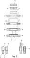
- the invention relates to the method for producing the first subunit 2 with the rod body 9, formed by the heat source, and the adjacent cavity 14, which will be described below with reference to FIGS Fig. 2 will be described in more detail.
- a double-length rod body 20 is fed and cut centrally into two individual rod body 9 simple length. Subsequently, the two rod body 9 are pulled apart and inserted a double-length tubular body 21 between the rod body 9, as in the upper representations of Fig. 2 can be seen.
- the double-length tubular body 21 can be cut in previous processing steps of pieces of pipe of a multiple length, then staggered and strung by air pressure to a sequence of double-length, identically aligned tubular bodies 21 with parallel longitudinal axes in a row, the width of the strip corresponds to the length of the double-length tubular body 21 ,
- the double-length tubular body 21 are first staggered after cutting and then pushed together by air pressure to the strip in the identical orientation.
- the pushing together can also be done mechanically via a counter surface.
- the pushing together By means of air pressure but is advantageous in that thereby the load on the double-length tubular body 21 is as low as possible, and it is also possible to move the double-length tubular body 21 to further reduce the burden on a kind of air cushion.
- a double-wide first wrapping strip 22 is fed, which is preferably wetted over the entire area with a glue and is wound in a rolling process to the double-length tubular body 21 and about 20 to 30% of the adjacent annular lateral surfaces of the rod body 9, whereby the Double-length tubular body 21 is connected to the two rod bodies 9 arranged on the end faces.
- the assembly thus created is cut through a central section through the double-length tubular body 21 into two first subunits 2 each consisting of a rod body 9 and a single-length tubular body 10, which are each interconnected by a first wrapping strip 6 simple width.
- the section through the double-length tubular body 21 takes place in a horizontal orientation of the double-length tubular body 21, which has the advantage that the rod body 9 and the double-length tubular body 21 are transported on a lateral surface of a transport drum with a horizontal axis of rotation, whereby a cut with a particularly high cut quality can be achieved. Further, the cut quality is improved by forming the cavity 14 for receiving the pellets 19 by the dimensionally stable double-length tubular body 21, which is then fixed to the rod body 9 by the double-width wrapping strip 22.
- the dimensionally stable, double-length tubular body 21 provides the cutting blade due to its dimensional stability such a high resistance that he during the cutting process not deformed. As a result, the cutting blade cuts through the double-length tubular body 21 in a clean and vertical cut with a high quality of cut.
- the two first subunits 2 are rotated in an orientation in which their longitudinal axes are aligned vertically, and in which the two cavities 14 are open at the top by the tubular body 10 via the rod bodies 9 are arranged, as in the lower representations of Fig. 2 can be seen.
- the pellets 19 are filled from above into the cavities 14.
- the process for producing the first subunits 2 is thus completed.
- the second subunit 3 in this case the tobacco rod, is then attached coaxially from above and connected to the first subunit 2 by means of the second wrapping strip 7.
- the third subunit 4 and the fourth subunit 5 are also successively coaxially attached and connected via the third wrapping strip 8 to the second subunit 3.
- the proposed manufacturing method of the first subunit 2 also has advantages for other subunits or segments of the HNB smoking article 1, provided that adjacent cavities must be provided thereon.
- the cavities themselves are thereby dimensionally stabilized, so that the fixation of the subunits by means of the wrapping strips is simplified.
- a dimensionally stable contact surface for bonding the wrapping strip is created by the tubular body 10.
- the subunits are each assembled with vertically oriented longitudinal axes, so that the tubular body 10 in this case also serves as a spacer for the adjoining adjacent subunit.
- a further advantage of the invention can be seen in the fact that the first subunit 2 can also be produced and temporarily stored in a prefabrication process. If activated carbon is used as a heat source, the cutting of the rod body 9 immediately after strand production makes sense, since the activated carbon can still be cut well in this state before it hardens by cooling.
- the first subunits 2 can be stored intermediately both after and before cutting the double-length tubular body 21.
Landscapes
- Manufacturing Of Cigar And Cigarette Tobacco (AREA)
- Cigarettes, Filters, And Manufacturing Of Filters (AREA)
- Packaging Of Annular Or Rod-Shaped Articles, Wearing Apparel, Cassettes, Or The Like (AREA)
Claims (14)
- Procédé pour produire un premier sous-ensemble (2) d'un article à fumer à chauffage sans combustion (1), présentant un corps formant tige (9) et une cavité (14) montée sur celui-ci, dans lequel- un corps tubulaire (10) est disposé et fixé sur une des faces frontales du corps formant tige (9), dans lequel- un corps tubulaire de longueur double (21) est disposé entre deux corps formant tiges (9) et relié à ceux-ci puis coupé au milieu, dans lequel- le corps tubulaire (10) est fixé sur le corps formant tige (9) au moyen d'une première bande d'enveloppement (6) collée au corps formant tige (9) et au corps tubulaire (10),caractérisé en ce que- le corps tubulaire de longueur double (21) est coupé au milieu avec un axe longitudinal orienté à l'horizontale, et- les deux premiers sous-ensembles (2) ainsi formés constitués respectivement d'un corps formant tige (9) présentant un corps tubulaire (10) maintenu sur celui-ci sont ensuite tournés dans une orientation verticale avec respectivement une cavité (14) des corps tubulaires (10) ouverte vers le haut.
- Procédé selon la revendication 1, caractérisé en ce que- la première bande d'enveloppement (6) est collée sur toute sa surface au corps tubulaire (10) et au corps formant tige (9).
- Procédé selon l'une des revendications 1 ou 2, caractérisé en ce que- le corps formant tige (9) est une source de chaleur, et- la première bande d'enveloppement (6) est collée sur une surface correspondant à 30 % maximum, de préférence 20 % à 30 %, de la surface latérale de la source de chaleur.
- Procédé selon l'une des revendications précédentes, caractérisé en ce que- le corps tubulaire (10) est revêtu sur le côté intérieur avec un revêtement métallique et/ou organique avant la fixation sur le corps formant tige (9).
- Procédé selon la revendication 4, caractérisé en ce que- le revêtement est stable jusqu'à une température d'au moins 350 degrés Celsius.
- Procédé selon la revendication 5, caractérisé en ce que- les corps formant tiges (9) et le corps tubulaire de longueur double (21) sont reliés les uns aux autres avant la coupe par une bande d'enveloppement de largeur double (22).
- Procédé selon l'une des revendications précédentes, caractérisé en ce que- le corps formant tige (9) et le corps tubulaire (10) sont reliés l'un à l'autre avec les axes longitudinaux orientés à l'horizontale pour former le premier sous-ensemble (2), et- le premier sous-ensemble (2) est ensuite tourné jusqu'à ce que les axes longitudinaux du corps formant tige (9) et du corps tubulaire (10) soient orientés à la verticale, et le corps tubulaire (10) soit disposé au-dessus du corps formant tige (9) avec la cavité (14) ouverte vers le haut, et- la cavité (14) est ensuite remplie par le haut avec une matière de remplissage.
- Procédé selon l'une des revendications précédentes, caractérisé en ce que- le corps tubulaire (10) est constitué de cellulose.
- Sous-ensemble (2) d'un article à fumer à chauffage sans combustion (1), présentant un corps formant tige (9) et une cavité (14) montée sur celui-ci, dans lequel- un corps tubulaire (10) est disposé et fixé sur une des faces frontales du corps formant tige (9), et- le corps tubulaire (10) est fixé sur le corps formant tige (9) au moyen d'une première bande d'enveloppement (6) collée au corps formant tige (9) et au corps tubulaire (10), caractérisé en ce que- la première bande d'enveloppement (6) est collée sur toute sa surface au corps tubulaire (10) et au corps formant tige (9).
- Sous-ensemble (2) selon la revendication 9, caractérisé en ce que- le corps formant tige (9) est une source de chaleur, et- la première bande d'enveloppement (6) est collée sur une surface correspondant à 30 % maximum, de préférence 20 % à 30 %, de la surface latérale de la source de chaleur.
- Sous-ensemble (2) selon l'une des revendications 9 ou 10, caractérisé en ce que- le corps tubulaire (10) est revêtu sur le côté intérieur avec un revêtement métallique et/ou organique avant la fixation sur le corps formant tige (9).
- Sous-ensemble (2) selon la revendication 11, caractérisé en ce que- le revêtement est stable jusqu'à une température d'au moins 350 degrés Celsius.
- Sous-ensemble (2) selon l'une des revendications 9 à 12, caractérisé en ce que- le corps tubulaire (10) est constitué de cellulose.
- Article à fumer à chauffage sans combustion (1) comprenant un sous-ensemble (2) selon l'une des revendications 9 à 13.
Priority Applications (1)
| Application Number | Priority Date | Filing Date | Title |
|---|---|---|---|
| PL16707098.6T PL3277107T5 (pl) | 2015-03-31 | 2016-02-29 | Sposób wytwarzania pierwszego członu artykułu tytoniowego HNB z prętowym korpusem i umieszczoną przy nim wnęką, taki człon i artykuł tytoniowy HNB |
Applications Claiming Priority (2)
| Application Number | Priority Date | Filing Date | Title |
|---|---|---|---|
| DE102015205768.2A DE102015205768A1 (de) | 2015-03-31 | 2015-03-31 | Verfahren zur Herstellung einer ersten Untereinheit eines HNB-Rauchartikels mit einem Stabkörper und einem daran angeordneten Hohlraum |
| PCT/EP2016/054196 WO2016155958A1 (fr) | 2015-03-31 | 2016-02-29 | Procédé pour produire un premier sous-ensemble d'un article à fumer à chauffage sans combustion, présentant un corps formant tige et une cavité montée dessus, sous-ensemble et article à fumer à chauffage sans combustion |
Publications (3)
| Publication Number | Publication Date |
|---|---|
| EP3277107A1 EP3277107A1 (fr) | 2018-02-07 |
| EP3277107B1 true EP3277107B1 (fr) | 2019-06-19 |
| EP3277107B2 EP3277107B2 (fr) | 2024-02-07 |
Family
ID=55446791
Family Applications (1)
| Application Number | Title | Priority Date | Filing Date |
|---|---|---|---|
| EP16707098.6A Active EP3277107B2 (fr) | 2015-03-31 | 2016-02-29 | Procédé pour produire un premier sous-ensemble d'un article à fumer à chauffage sans combustion, présentant un corps formant tige et une cavité montée dessus, sous-ensemble et article à fumer à chauffage sans combustion |
Country Status (6)
| Country | Link |
|---|---|
| US (1) | US10398168B2 (fr) |
| EP (1) | EP3277107B2 (fr) |
| CN (1) | CN107529823B (fr) |
| DE (1) | DE102015205768A1 (fr) |
| PL (1) | PL3277107T5 (fr) |
| WO (1) | WO2016155958A1 (fr) |
Families Citing this family (33)
| Publication number | Priority date | Publication date | Assignee | Title |
|---|---|---|---|---|
| US11744296B2 (en) | 2015-12-10 | 2023-09-05 | R. J. Reynolds Tobacco Company | Smoking article |
| US10314334B2 (en) | 2015-12-10 | 2019-06-11 | R.J. Reynolds Tobacco Company | Smoking article |
| US11717018B2 (en) * | 2016-02-24 | 2023-08-08 | R.J. Reynolds Tobacco Company | Smoking article comprising aerogel |
| EP3727065A1 (fr) * | 2017-12-22 | 2020-10-28 | G.D. S.p.A | Procédé de fabrication d'une sous-unité d'un article à fumer |
| WO2019141373A1 (fr) | 2018-01-19 | 2019-07-25 | Hauni Maschinenbau Gmbh | Kit d'assemblage pour un article à fumer hnb, support de module pour un article à fumer hnb et article à fumer hnb |
| DE102018127927A1 (de) * | 2018-05-28 | 2019-11-28 | Hauni Maschinenbau Gmbh | Anordnung und Basisteil für einen Inhalator, und Inhalator |
| DE102018211380A1 (de) * | 2018-07-10 | 2020-01-16 | Hauni Maschinenbau Gmbh | Vorrichtung und Verfahren zum Abtrennen von stabförmigen Segmenten der Tabak verarbeitenden Industrie von einem Strang |
| US11723399B2 (en) | 2018-07-13 | 2023-08-15 | R.J. Reynolds Tobacco Company | Smoking article with detachable cartridge |
| US20210315264A1 (en) * | 2018-10-29 | 2021-10-14 | Nerudia Limited | Smoking substitute consumable |
| US12478112B2 (en) | 2018-10-30 | 2025-11-25 | R.J. Reynolds Tobacco Company | Smoking article cartridge |
| EP4193851A1 (fr) * | 2018-12-20 | 2023-06-14 | Philip Morris Products S.A. | Article de génération d'aérosol avec segment creux ventilé |
| DE102019133945A1 (de) | 2019-07-05 | 2020-06-25 | Hauni Maschinenbau Gmbh | Vorrichtung und Verfahren zum Abtrennen von stabförmigen Segmenten der Tabak verarbeitenden Industrie von einem stabförmigen Artikel |
| US12075819B2 (en) | 2019-07-18 | 2024-09-03 | R.J. Reynolds Tobacco Company | Aerosol delivery device with consumable cartridge |
| US12022859B2 (en) | 2019-07-18 | 2024-07-02 | R.J. Reynolds Tobacco Company | Thermal energy absorbers for tobacco heating products |
| US12569004B2 (en) | 2019-07-19 | 2026-03-10 | R.J. Reynolds Tobacco Company | Aerosol delivery device with separable heat source and substrate |
| US11395510B2 (en) | 2019-07-19 | 2022-07-26 | R.J. Reynolds Tobacco Company | Aerosol delivery device with rotatable enclosure for cartridge |
| US12232542B2 (en) | 2019-07-19 | 2025-02-25 | R.J. Reynolds Tobacco Company | Aerosol delivery device with sliding sleeve |
| US11330838B2 (en) | 2019-07-19 | 2022-05-17 | R. J. Reynolds Tobacco Company | Holder for aerosol delivery device with detachable cartridge |
| US12082607B2 (en) | 2019-07-19 | 2024-09-10 | R.J. Reynolds Tobacco Company | Aerosol delivery device with clamshell holder for cartridge |
| US12484610B2 (en) | 2020-04-16 | 2025-12-02 | R.J. Reynolds Tobacco Company | Aerosol delivery device including a segregated substrate |
| US11589616B2 (en) | 2020-04-29 | 2023-02-28 | R.J. Reynolds Tobacco Company | Aerosol delivery device with sliding and axially rotating locking mechanism |
| US11439185B2 (en) | 2020-04-29 | 2022-09-13 | R. J. Reynolds Tobacco Company | Aerosol delivery device with sliding and transversely rotating locking mechanism |
| US12426634B2 (en) | 2021-04-02 | 2025-09-30 | R. J. Reynolds Tobacco Company | Aerosol delivery device with integrated lighter |
| US12426633B2 (en) | 2021-04-02 | 2025-09-30 | R. J. Reynolds Tobacco Company | Aerosol delivery device with integrated inductive heater |
| US12433340B2 (en) | 2021-04-02 | 2025-10-07 | R. J. Reynolds Tobacco Company | Aerosol delivery device consumable unit |
| US11825872B2 (en) | 2021-04-02 | 2023-11-28 | R.J. Reynolds Tobacco Company | Aerosol delivery device with protective sleeve |
| US12250969B2 (en) | 2021-04-02 | 2025-03-18 | R. J. Reynolds Tobacco Company | Aerosol delivery device with modular lighter |
| US12426637B2 (en) | 2021-08-17 | 2025-09-30 | Rai Strategic Holdings, Inc. | Inductively heated aerosol delivery device consumable |
| US12357024B2 (en) | 2022-08-30 | 2025-07-15 | R. J. Reynolds Tobacco Company | Aerosol delivery device with static ignitor contacts |
| US12329199B2 (en) | 2022-08-30 | 2025-06-17 | R.J. Reynolds Tobaco Company | Aerosol delivery device with improved mouthpieces |
| US12564220B2 (en) | 2022-12-14 | 2026-03-03 | R.J. Reynolds Tobacco Company | Aerosol delivery device with automatic consumable loading and ejecting |
| US12471639B2 (en) | 2022-12-14 | 2025-11-18 | R.J. Reynolds Tobacco Company | Aerosol delivery device with improved cartridge loading |
| US12564221B2 (en) | 2022-12-14 | 2026-03-03 | R.J. Reynolds Tobacco Company | Aerosol delivery device with deflectable or collapsible housing |
Citations (13)
| Publication number | Priority date | Publication date | Assignee | Title |
|---|---|---|---|---|
| US3517480A (en) | 1968-02-14 | 1970-06-30 | Reynolds Tobacco Co R | Apparatus for making loose granular filters |
| EP0174645A2 (fr) | 1984-09-14 | 1986-03-19 | R.J. Reynolds Tobacco Company | Article pour fumer |
| EP0336457A2 (fr) | 1985-08-26 | 1989-10-11 | R.J. Reynolds Tobacco Company | Article à fumer |
| WO1996032854A2 (fr) | 1995-04-20 | 1996-10-24 | Philip Morris Products Inc. | Cigarette et dispositif chauffant destines a un systeme electrique servant a fumer |
| WO2009035768A2 (fr) | 2007-09-12 | 2009-03-19 | Howard Hughes Medical Institute | Imagerie non linéaire utilisant des séparateurs d'impulsions passifs et technologies apparentées |
| US20120000477A1 (en) | 2010-06-30 | 2012-01-05 | Rj Reynolds Tobacco Company | Degradable adhesive compositions for smoking articles |
| US20120067360A1 (en) | 2010-05-06 | 2012-03-22 | Billy Tyrone Conner | Segmented smoking article with substrate cavity |
| EP2550879A1 (fr) | 2010-03-26 | 2013-01-30 | Japan Tobacco, Inc. | Article à fumer |
| WO2013190036A1 (fr) | 2012-06-21 | 2013-12-27 | Philip Morris Products S.A. | Article à fumer destiné à être utilisé avec un élément chauffant interne |
| WO2014023555A1 (fr) | 2012-08-06 | 2014-02-13 | Philip Morris Products S.A. | Procédé de formation d'articles à fumer avec cavités d'extrémité de bouche |
| EP2777408A1 (fr) | 2013-03-15 | 2014-09-17 | HAUNI Maschinenbau AG | Procédé et appareil pour l'assemblage de produits cylindriques à segments multiples, tels que des produits du tabac |
| US20140366901A1 (en) | 2011-12-21 | 2014-12-18 | Japan Tobacco Inc. | Paper tube and flavor inhaler |
| WO2016088064A1 (fr) * | 2014-12-02 | 2016-06-09 | G.D Societa' Per Azioni | Machine et procédé de production d'articles sensiblement cylindriques de l'industrie du tabac |
Family Cites Families (26)
| Publication number | Priority date | Publication date | Assignee | Title |
|---|---|---|---|---|
| US5024242A (en) * | 1989-04-27 | 1991-06-18 | Philip Morris Incorporated | Methods and apparatus for making multiple component smoking articles |
| US5469871A (en) * | 1992-09-17 | 1995-11-28 | R. J. Reynolds Tobacco Company | Cigarette and method of making same |
| US7004896B2 (en) | 2001-01-29 | 2006-02-28 | Hauni Maschinenbau Gmbh | Method and arrangement for producing compound filters |
| DE10105010A1 (de) * | 2001-01-29 | 2002-09-12 | Hauni Maschinenbau Ag | Verfahren und Einrichtung zur Herstellung von Mehrfachfiltern |
| US20040173229A1 (en) | 2003-03-05 | 2004-09-09 | Crooks Evon Llewellyn | Smoking article comprising ultrafine particles |
| US8469036B2 (en) * | 2003-11-07 | 2013-06-25 | U.S. Smokeless Tobacco Company Llc | Tobacco compositions |
| JP4525618B2 (ja) * | 2006-03-06 | 2010-08-18 | ソニー株式会社 | 映像監視システムおよび映像監視プログラム |
| US7789089B2 (en) * | 2006-08-04 | 2010-09-07 | R. J. Reynolds Tobacco Company | Filtered cigarette possessing tipping material |
| UA97004C2 (ru) * | 2007-08-10 | 2011-12-26 | Филип Моррис Продактс С.А. | Дистилляционное курительное изделие |
| CN201104487Y (zh) * | 2007-11-09 | 2008-08-27 | 纪峰 | 一种烟侣 |
| GB0809135D0 (en) * | 2008-05-20 | 2008-06-25 | British American Tobacco Co | Apparatus and method for making a smoking article |
| EP2210509A1 (fr) * | 2008-12-30 | 2010-07-28 | Philip Morris Products S.A. | Appareil et procédé pour combiner des composants d'articles à fumer |
| US8464726B2 (en) | 2009-08-24 | 2013-06-18 | R.J. Reynolds Tobacco Company | Segmented smoking article with insulation mat |
| SG184274A1 (en) * | 2010-03-26 | 2012-11-29 | Philip Morris Prod | Smoking article with heat resistant sheet material |
| FR2960794B1 (fr) * | 2010-06-08 | 2012-07-27 | Millipore Corp | Dispositif pour une installation de traitement de liquide biologique |
| DK2415363T3 (da) * | 2010-08-02 | 2014-06-10 | Imp Tobacco Ltd | Filtercigarillo og fremgangsmåde til fremstilling af filtercigarillos |
| IN2014CN02160A (fr) * | 2011-09-20 | 2015-05-29 | Reynolds Tobacco Co R | |
| EP2782462B1 (fr) * | 2011-11-07 | 2020-06-03 | Philip Morris Products S.a.s. | Article à fumer doté d'un composant de libération de vapeur amovible |
| EP2625975A1 (fr) * | 2012-02-13 | 2013-08-14 | Philip Morris Products S.A. | Article de génération d'aérosol avec un élément de refroidissement d'aérosol |
| CN104379004B (zh) * | 2012-04-30 | 2019-12-06 | 菲利普莫里斯生产公司 | 两部分多部件组合机 |
| WO2015022321A1 (fr) * | 2013-08-13 | 2015-02-19 | Philip Morris Products S.A. | Article à fumer doté d'un élément thermoconducteur séparé radialement unique |
| CN203424296U (zh) * | 2013-08-15 | 2014-02-12 | 刘秋明 | 一种电子烟 |
| US20150157052A1 (en) * | 2013-12-05 | 2015-06-11 | R. J. Reynolds Tobacco Company | Smoking article and associated manufacturing method |
| CN203748666U (zh) * | 2013-12-23 | 2014-08-06 | 湖南中烟工业有限责任公司 | 一种带自熄装置的低温卷烟及卷烟烟体 |
| CN103859597A (zh) * | 2014-04-02 | 2014-06-18 | 川渝中烟工业有限责任公司 | 加热不燃烧的卷烟烟支 |
| CN104082861A (zh) * | 2014-05-16 | 2014-10-08 | 何国兴 | 一次性电子雪茄烟 |
-
2015
- 2015-03-31 DE DE102015205768.2A patent/DE102015205768A1/de not_active Ceased
-
2016
- 2016-02-29 WO PCT/EP2016/054196 patent/WO2016155958A1/fr not_active Ceased
- 2016-02-29 US US15/563,893 patent/US10398168B2/en active Active
- 2016-02-29 EP EP16707098.6A patent/EP3277107B2/fr active Active
- 2016-02-29 PL PL16707098.6T patent/PL3277107T5/pl unknown
- 2016-02-29 CN CN201680019990.0A patent/CN107529823B/zh active Active
Patent Citations (14)
| Publication number | Priority date | Publication date | Assignee | Title |
|---|---|---|---|---|
| US3517480A (en) | 1968-02-14 | 1970-06-30 | Reynolds Tobacco Co R | Apparatus for making loose granular filters |
| EP0174645A2 (fr) | 1984-09-14 | 1986-03-19 | R.J. Reynolds Tobacco Company | Article pour fumer |
| EP0337508A2 (fr) | 1984-09-14 | 1989-10-18 | R.J. Reynolds Tobacco Company | Elément combustible carboné pour article à fumer |
| EP0336457A2 (fr) | 1985-08-26 | 1989-10-11 | R.J. Reynolds Tobacco Company | Article à fumer |
| WO1996032854A2 (fr) | 1995-04-20 | 1996-10-24 | Philip Morris Products Inc. | Cigarette et dispositif chauffant destines a un systeme electrique servant a fumer |
| WO2009035768A2 (fr) | 2007-09-12 | 2009-03-19 | Howard Hughes Medical Institute | Imagerie non linéaire utilisant des séparateurs d'impulsions passifs et technologies apparentées |
| EP2550879A1 (fr) | 2010-03-26 | 2013-01-30 | Japan Tobacco, Inc. | Article à fumer |
| US20120067360A1 (en) | 2010-05-06 | 2012-03-22 | Billy Tyrone Conner | Segmented smoking article with substrate cavity |
| US20120000477A1 (en) | 2010-06-30 | 2012-01-05 | Rj Reynolds Tobacco Company | Degradable adhesive compositions for smoking articles |
| US20140366901A1 (en) | 2011-12-21 | 2014-12-18 | Japan Tobacco Inc. | Paper tube and flavor inhaler |
| WO2013190036A1 (fr) | 2012-06-21 | 2013-12-27 | Philip Morris Products S.A. | Article à fumer destiné à être utilisé avec un élément chauffant interne |
| WO2014023555A1 (fr) | 2012-08-06 | 2014-02-13 | Philip Morris Products S.A. | Procédé de formation d'articles à fumer avec cavités d'extrémité de bouche |
| EP2777408A1 (fr) | 2013-03-15 | 2014-09-17 | HAUNI Maschinenbau AG | Procédé et appareil pour l'assemblage de produits cylindriques à segments multiples, tels que des produits du tabac |
| WO2016088064A1 (fr) * | 2014-12-02 | 2016-06-09 | G.D Societa' Per Azioni | Machine et procédé de production d'articles sensiblement cylindriques de l'industrie du tabac |
Also Published As
| Publication number | Publication date |
|---|---|
| US20180116280A1 (en) | 2018-05-03 |
| EP3277107A1 (fr) | 2018-02-07 |
| CN107529823B (zh) | 2021-06-22 |
| EP3277107B2 (fr) | 2024-02-07 |
| CN107529823A (zh) | 2018-01-02 |
| DE102015205768A1 (de) | 2016-10-06 |
| US10398168B2 (en) | 2019-09-03 |
| WO2016155958A1 (fr) | 2016-10-06 |
| PL3277107T5 (pl) | 2024-04-08 |
| PL3277107T3 (pl) | 2019-12-31 |
Similar Documents
| Publication | Publication Date | Title |
|---|---|---|
| EP3277107B1 (fr) | Procédé pour produire un premier sous-ensemble d'un article à fumer à chauffage sans combustion, présentant un corps formant tige et une cavité montée dessus, sous-ensemble et article à fumer à chauffage sans combustion | |
| EP3332655B1 (fr) | Petit tube double couche de l'industrie de traitement du tabac ainsi que procédé de fabrication d'un tel petit tube | |
| EP3033952B1 (fr) | Tube double couche de l'industrie de traitement du tabac et dispositif et procede de fabrication d'un tel tube | |
| CH645252A5 (de) | Zigarettenfilter. | |
| EP3298909B1 (fr) | Fabrication de produits à fumer | |
| DE3311902C2 (de) | Filtermundstück für Zigaretten | |
| EP2762014A2 (fr) | Transport d'articles en forme de tige de l'industrie de traitement du tabac avec des objets sensibles à la pression | |
| DE102017101929A1 (de) | Verfahren zum Herstellen eines Strangs der Tabak verarbeitenden Industrie sowie Strangformungsvorrichtung | |
| DE102017108789A1 (de) | Verfahren und Strangmaschine zum Herstellen von doppellagigen Röhrchen der Tabak verarbeitenden Industrie | |
| WO2018083180A1 (fr) | Article à fumer en forme de tige et dispositif pour sa fabrication | |
| DE3147531A1 (de) | Zigarettenfilter | |
| DE3225071C2 (de) | Ventiliertes Zigarettenfilter | |
| EP3641572A1 (fr) | Procédé pour la fabrication de produits à fumer | |
| CH672396A5 (fr) | ||
| EP1397965B1 (fr) | Injection d'un milieu dans segments d'un filtre | |
| DE102018113188A1 (de) | Stabförmiger HNB-Artikel sowie Verfahren zum Herstellen und zum Einsetzen eines stabförmigen HNB-Artikels | |
| DE2409023A1 (de) | Filter fuer tabakrauch | |
| EP2481302B1 (fr) | Manchon de filtre de cigarettes doté d'un support d'extrémité ainsi que procédé de fabrication d'un manchon de filtre de cigarettes doté d'un support d'extrémité | |
| DE102014221146A1 (de) | Überführungsvorrichtung einer Filterstrangmaschine und Verfahren zum Betrieb einer Filterstrangmaschine der Tabak verarbeitenden Industrie | |
| DE102009040092A1 (de) | Verfahren und Vorrichtung zur Herstellung eines Filterstrangs | |
| DE4206509C3 (de) | Verfahren zur Herstellung einer Cigarettenpapierhülse | |
| WO2019141373A1 (fr) | Kit d'assemblage pour un article à fumer hnb, support de module pour un article à fumer hnb et article à fumer hnb | |
| DE102018103635A1 (de) | Multisegmentproduktherstellung der Tabak verarbeitenden Industrie | |
| EP3262959B1 (fr) | Positionnement de produits en forme de tiges de l'industrie de traitement du tabac dans une machine d'insertion | |
| EP0482634B1 (fr) | Procédé de fabrication de tubes de cigarette pour cigarettes sans filtre |
Legal Events
| Date | Code | Title | Description |
|---|---|---|---|
| STAA | Information on the status of an ep patent application or granted ep patent |
Free format text: STATUS: THE INTERNATIONAL PUBLICATION HAS BEEN MADE |
|
| TPAC | Observations filed by third parties |
Free format text: ORIGINAL CODE: EPIDOSNTIPA |
|
| PUAI | Public reference made under article 153(3) epc to a published international application that has entered the european phase |
Free format text: ORIGINAL CODE: 0009012 |
|
| STAA | Information on the status of an ep patent application or granted ep patent |
Free format text: STATUS: REQUEST FOR EXAMINATION WAS MADE |
|
| 17P | Request for examination filed |
Effective date: 20171025 |
|
| AK | Designated contracting states |
Kind code of ref document: A1 Designated state(s): AL AT BE BG CH CY CZ DE DK EE ES FI FR GB GR HR HU IE IS IT LI LT LU LV MC MK MT NL NO PL PT RO RS SE SI SK SM TR |
|
| AX | Request for extension of the european patent |
Extension state: BA ME |
|
| TPAC | Observations filed by third parties |
Free format text: ORIGINAL CODE: EPIDOSNTIPA |
|
| DAV | Request for validation of the european patent (deleted) | ||
| DAX | Request for extension of the european patent (deleted) | ||
| STAA | Information on the status of an ep patent application or granted ep patent |
Free format text: STATUS: EXAMINATION IS IN PROGRESS |
|
| 17Q | First examination report despatched |
Effective date: 20180921 |
|
| GRAP | Despatch of communication of intention to grant a patent |
Free format text: ORIGINAL CODE: EPIDOSNIGR1 |
|
| STAA | Information on the status of an ep patent application or granted ep patent |
Free format text: STATUS: GRANT OF PATENT IS INTENDED |
|
| INTG | Intention to grant announced |
Effective date: 20190116 |
|
| GRAS | Grant fee paid |
Free format text: ORIGINAL CODE: EPIDOSNIGR3 |
|
| GRAA | (expected) grant |
Free format text: ORIGINAL CODE: 0009210 |
|
| STAA | Information on the status of an ep patent application or granted ep patent |
Free format text: STATUS: THE PATENT HAS BEEN GRANTED |
|
| AK | Designated contracting states |
Kind code of ref document: B1 Designated state(s): AL AT BE BG CH CY CZ DE DK EE ES FI FR GB GR HR HU IE IS IT LI LT LU LV MC MK MT NL NO PL PT RO RS SE SI SK SM TR |
|
| REG | Reference to a national code |
Ref country code: GB Ref legal event code: FG4D Free format text: NOT ENGLISH |
|
| REG | Reference to a national code |
Ref country code: CH Ref legal event code: EP |
|
| REG | Reference to a national code |
Ref country code: IE Ref legal event code: FG4D Free format text: LANGUAGE OF EP DOCUMENT: GERMAN |
|
| REG | Reference to a national code |
Ref country code: AT Ref legal event code: REF Ref document number: 1144358 Country of ref document: AT Kind code of ref document: T Effective date: 20190715 |
|
| REG | Reference to a national code |
Ref country code: DE Ref legal event code: R096 Ref document number: 502016005144 Country of ref document: DE |
|
| REG | Reference to a national code |
Ref country code: NL Ref legal event code: FP |
|
| PG25 | Lapsed in a contracting state [announced via postgrant information from national office to epo] |
Ref country code: AL Free format text: LAPSE BECAUSE OF FAILURE TO SUBMIT A TRANSLATION OF THE DESCRIPTION OR TO PAY THE FEE WITHIN THE PRESCRIBED TIME-LIMIT Effective date: 20190619 Ref country code: LT Free format text: LAPSE BECAUSE OF FAILURE TO SUBMIT A TRANSLATION OF THE DESCRIPTION OR TO PAY THE FEE WITHIN THE PRESCRIBED TIME-LIMIT Effective date: 20190619 Ref country code: HR Free format text: LAPSE BECAUSE OF FAILURE TO SUBMIT A TRANSLATION OF THE DESCRIPTION OR TO PAY THE FEE WITHIN THE PRESCRIBED TIME-LIMIT Effective date: 20190619 Ref country code: NO Free format text: LAPSE BECAUSE OF FAILURE TO SUBMIT A TRANSLATION OF THE DESCRIPTION OR TO PAY THE FEE WITHIN THE PRESCRIBED TIME-LIMIT Effective date: 20190919 Ref country code: SE Free format text: LAPSE BECAUSE OF FAILURE TO SUBMIT A TRANSLATION OF THE DESCRIPTION OR TO PAY THE FEE WITHIN THE PRESCRIBED TIME-LIMIT Effective date: 20190619 Ref country code: FI Free format text: LAPSE BECAUSE OF FAILURE TO SUBMIT A TRANSLATION OF THE DESCRIPTION OR TO PAY THE FEE WITHIN THE PRESCRIBED TIME-LIMIT Effective date: 20190619 |
|
| REG | Reference to a national code |
Ref country code: LT Ref legal event code: MG4D |
|
| PG25 | Lapsed in a contracting state [announced via postgrant information from national office to epo] |
Ref country code: RS Free format text: LAPSE BECAUSE OF FAILURE TO SUBMIT A TRANSLATION OF THE DESCRIPTION OR TO PAY THE FEE WITHIN THE PRESCRIBED TIME-LIMIT Effective date: 20190619 Ref country code: LV Free format text: LAPSE BECAUSE OF FAILURE TO SUBMIT A TRANSLATION OF THE DESCRIPTION OR TO PAY THE FEE WITHIN THE PRESCRIBED TIME-LIMIT Effective date: 20190619 Ref country code: BG Free format text: LAPSE BECAUSE OF FAILURE TO SUBMIT A TRANSLATION OF THE DESCRIPTION OR TO PAY THE FEE WITHIN THE PRESCRIBED TIME-LIMIT Effective date: 20190919 Ref country code: GR Free format text: LAPSE BECAUSE OF FAILURE TO SUBMIT A TRANSLATION OF THE DESCRIPTION OR TO PAY THE FEE WITHIN THE PRESCRIBED TIME-LIMIT Effective date: 20190920 |
|
| PG25 | Lapsed in a contracting state [announced via postgrant information from national office to epo] |
Ref country code: SK Free format text: LAPSE BECAUSE OF FAILURE TO SUBMIT A TRANSLATION OF THE DESCRIPTION OR TO PAY THE FEE WITHIN THE PRESCRIBED TIME-LIMIT Effective date: 20190619 Ref country code: RO Free format text: LAPSE BECAUSE OF FAILURE TO SUBMIT A TRANSLATION OF THE DESCRIPTION OR TO PAY THE FEE WITHIN THE PRESCRIBED TIME-LIMIT Effective date: 20190619 Ref country code: CZ Free format text: LAPSE BECAUSE OF FAILURE TO SUBMIT A TRANSLATION OF THE DESCRIPTION OR TO PAY THE FEE WITHIN THE PRESCRIBED TIME-LIMIT Effective date: 20190619 Ref country code: PT Free format text: LAPSE BECAUSE OF FAILURE TO SUBMIT A TRANSLATION OF THE DESCRIPTION OR TO PAY THE FEE WITHIN THE PRESCRIBED TIME-LIMIT Effective date: 20191021 Ref country code: EE Free format text: LAPSE BECAUSE OF FAILURE TO SUBMIT A TRANSLATION OF THE DESCRIPTION OR TO PAY THE FEE WITHIN THE PRESCRIBED TIME-LIMIT Effective date: 20190619 |
|
| PG25 | Lapsed in a contracting state [announced via postgrant information from national office to epo] |
Ref country code: ES Free format text: LAPSE BECAUSE OF FAILURE TO SUBMIT A TRANSLATION OF THE DESCRIPTION OR TO PAY THE FEE WITHIN THE PRESCRIBED TIME-LIMIT Effective date: 20190619 Ref country code: SM Free format text: LAPSE BECAUSE OF FAILURE TO SUBMIT A TRANSLATION OF THE DESCRIPTION OR TO PAY THE FEE WITHIN THE PRESCRIBED TIME-LIMIT Effective date: 20190619 Ref country code: IS Free format text: LAPSE BECAUSE OF FAILURE TO SUBMIT A TRANSLATION OF THE DESCRIPTION OR TO PAY THE FEE WITHIN THE PRESCRIBED TIME-LIMIT Effective date: 20191019 |
|
| REG | Reference to a national code |
Ref country code: DE Ref legal event code: R026 Ref document number: 502016005144 Country of ref document: DE |
|
| PLBI | Opposition filed |
Free format text: ORIGINAL CODE: 0009260 |
|
| PG25 | Lapsed in a contracting state [announced via postgrant information from national office to epo] |
Ref country code: TR Free format text: LAPSE BECAUSE OF FAILURE TO SUBMIT A TRANSLATION OF THE DESCRIPTION OR TO PAY THE FEE WITHIN THE PRESCRIBED TIME-LIMIT Effective date: 20190619 |
|
| 26 | Opposition filed |
Opponent name: G.D S.P.A. Effective date: 20200319 |
|
| PG25 | Lapsed in a contracting state [announced via postgrant information from national office to epo] |
Ref country code: DK Free format text: LAPSE BECAUSE OF FAILURE TO SUBMIT A TRANSLATION OF THE DESCRIPTION OR TO PAY THE FEE WITHIN THE PRESCRIBED TIME-LIMIT Effective date: 20190619 |
|
| PG25 | Lapsed in a contracting state [announced via postgrant information from national office to epo] |
Ref country code: IS Free format text: LAPSE BECAUSE OF FAILURE TO SUBMIT A TRANSLATION OF THE DESCRIPTION OR TO PAY THE FEE WITHIN THE PRESCRIBED TIME-LIMIT Effective date: 20200224 |
|
| PLAX | Notice of opposition and request to file observation + time limit sent |
Free format text: ORIGINAL CODE: EPIDOSNOBS2 |
|
| PG2D | Information on lapse in contracting state deleted |
Ref country code: IS |
|
| PG25 | Lapsed in a contracting state [announced via postgrant information from national office to epo] |
Ref country code: SI Free format text: LAPSE BECAUSE OF FAILURE TO SUBMIT A TRANSLATION OF THE DESCRIPTION OR TO PAY THE FEE WITHIN THE PRESCRIBED TIME-LIMIT Effective date: 20190619 |
|
| REG | Reference to a national code |
Ref country code: CH Ref legal event code: PL |
|
| PLBB | Reply of patent proprietor to notice(s) of opposition received |
Free format text: ORIGINAL CODE: EPIDOSNOBS3 |
|
| GBPC | Gb: european patent ceased through non-payment of renewal fee |
Effective date: 20200229 |
|
| REG | Reference to a national code |
Ref country code: BE Ref legal event code: MM Effective date: 20200229 |
|
| PG25 | Lapsed in a contracting state [announced via postgrant information from national office to epo] |
Ref country code: MC Free format text: LAPSE BECAUSE OF FAILURE TO SUBMIT A TRANSLATION OF THE DESCRIPTION OR TO PAY THE FEE WITHIN THE PRESCRIBED TIME-LIMIT Effective date: 20190619 Ref country code: LU Free format text: LAPSE BECAUSE OF NON-PAYMENT OF DUE FEES Effective date: 20200229 |
|
| PG25 | Lapsed in a contracting state [announced via postgrant information from national office to epo] |
Ref country code: LI Free format text: LAPSE BECAUSE OF NON-PAYMENT OF DUE FEES Effective date: 20200229 Ref country code: CH Free format text: LAPSE BECAUSE OF NON-PAYMENT OF DUE FEES Effective date: 20200229 |
|
| PG25 | Lapsed in a contracting state [announced via postgrant information from national office to epo] |
Ref country code: FR Free format text: LAPSE BECAUSE OF NON-PAYMENT OF DUE FEES Effective date: 20200229 Ref country code: GB Free format text: LAPSE BECAUSE OF NON-PAYMENT OF DUE FEES Effective date: 20200229 Ref country code: IE Free format text: LAPSE BECAUSE OF NON-PAYMENT OF DUE FEES Effective date: 20200229 |
|
| PG25 | Lapsed in a contracting state [announced via postgrant information from national office to epo] |
Ref country code: BE Free format text: LAPSE BECAUSE OF NON-PAYMENT OF DUE FEES Effective date: 20200229 |
|
| REG | Reference to a national code |
Ref country code: CH Ref legal event code: PK Free format text: BERICHTIGUNGEN |
|
| APBM | Appeal reference recorded |
Free format text: ORIGINAL CODE: EPIDOSNREFNO |
|
| APBP | Date of receipt of notice of appeal recorded |
Free format text: ORIGINAL CODE: EPIDOSNNOA2O |
|
| APAH | Appeal reference modified |
Free format text: ORIGINAL CODE: EPIDOSCREFNO |
|
| RIC2 | Information provided on ipc code assigned after grant |
Ipc: A24C 5/00 20200101AFI20211014BHEP |
|
| APBQ | Date of receipt of statement of grounds of appeal recorded |
Free format text: ORIGINAL CODE: EPIDOSNNOA3O |
|
| REG | Reference to a national code |
Ref country code: AT Ref legal event code: MM01 Ref document number: 1144358 Country of ref document: AT Kind code of ref document: T Effective date: 20210228 |
|
| PG25 | Lapsed in a contracting state [announced via postgrant information from national office to epo] |
Ref country code: AT Free format text: LAPSE BECAUSE OF NON-PAYMENT OF DUE FEES Effective date: 20210228 |
|
| PG25 | Lapsed in a contracting state [announced via postgrant information from national office to epo] |
Ref country code: MT Free format text: LAPSE BECAUSE OF FAILURE TO SUBMIT A TRANSLATION OF THE DESCRIPTION OR TO PAY THE FEE WITHIN THE PRESCRIBED TIME-LIMIT Effective date: 20190619 Ref country code: CY Free format text: LAPSE BECAUSE OF FAILURE TO SUBMIT A TRANSLATION OF THE DESCRIPTION OR TO PAY THE FEE WITHIN THE PRESCRIBED TIME-LIMIT Effective date: 20190619 |
|
| PG25 | Lapsed in a contracting state [announced via postgrant information from national office to epo] |
Ref country code: MK Free format text: LAPSE BECAUSE OF FAILURE TO SUBMIT A TRANSLATION OF THE DESCRIPTION OR TO PAY THE FEE WITHIN THE PRESCRIBED TIME-LIMIT Effective date: 20190619 |
|
| REG | Reference to a national code |
Ref country code: DE Ref legal event code: R081 Ref document number: 502016005144 Country of ref document: DE Owner name: KOERBER TECHNOLOGIES GMBH, DE Free format text: FORMER OWNER: HAUNI MASCHINENBAU GMBH, 21033 HAMBURG, DE |
|
| REG | Reference to a national code |
Ref country code: NL Ref legal event code: HC Owner name: KOERBER TECHNOLOGIES GMBH; DE Free format text: DETAILS ASSIGNMENT: CHANGE OF OWNER(S), CHANGE OF OWNER(S) NAME; FORMER OWNER NAME: HAUNI MASCHINENBAU GMBH Effective date: 20221031 |
|
| RAP4 | Party data changed (patent owner data changed or rights of a patent transferred) |
Owner name: KOERBER TECHNOLOGIES GMBH |
|
| APBU | Appeal procedure closed |
Free format text: ORIGINAL CODE: EPIDOSNNOA9O |
|
| P01 | Opt-out of the competence of the unified patent court (upc) registered |
Effective date: 20230616 |
|
| PUAH | Patent maintained in amended form |
Free format text: ORIGINAL CODE: 0009272 |
|
| STAA | Information on the status of an ep patent application or granted ep patent |
Free format text: STATUS: PATENT MAINTAINED AS AMENDED |
|
| 27A | Patent maintained in amended form |
Effective date: 20240207 |
|
| AK | Designated contracting states |
Kind code of ref document: B2 Designated state(s): AL AT BE BG CH CY CZ DE DK EE ES FI FR GB GR HR HU IE IS IT LI LT LU LV MC MK MT NL NO PL PT RO RS SE SI SK SM TR |
|
| REG | Reference to a national code |
Ref country code: DE Ref legal event code: R102 Ref document number: 502016005144 Country of ref document: DE |
|
| REG | Reference to a national code |
Ref country code: NL Ref legal event code: FP |
|
| PGFP | Annual fee paid to national office [announced via postgrant information from national office to epo] |
Ref country code: NL Payment date: 20250224 Year of fee payment: 10 |
|
| PGFP | Annual fee paid to national office [announced via postgrant information from national office to epo] |
Ref country code: PL Payment date: 20250128 Year of fee payment: 10 |
|
| PGFP | Annual fee paid to national office [announced via postgrant information from national office to epo] |
Ref country code: DE Payment date: 20260303 Year of fee payment: 11 |
|
| PGFP | Annual fee paid to national office [announced via postgrant information from national office to epo] |
Ref country code: IT Payment date: 20260227 Year of fee payment: 11 |