EP3277996B1 - Gaskochstelle mit hauptgasleitungsanordnung - Google Patents
Gaskochstelle mit hauptgasleitungsanordnung Download PDFInfo
- Publication number
- EP3277996B1 EP3277996B1 EP16709595.9A EP16709595A EP3277996B1 EP 3277996 B1 EP3277996 B1 EP 3277996B1 EP 16709595 A EP16709595 A EP 16709595A EP 3277996 B1 EP3277996 B1 EP 3277996B1
- Authority
- EP
- European Patent Office
- Prior art keywords
- flange
- gas line
- main gas
- connecting piece
- gas
- Prior art date
- Legal status (The legal status is an assumption and is not a legal conclusion. Google has not performed a legal analysis and makes no representation as to the accuracy of the status listed.)
- Active
Links
Images


Classifications
-
- F—MECHANICAL ENGINEERING; LIGHTING; HEATING; WEAPONS; BLASTING
- F16—ENGINEERING ELEMENTS AND UNITS; GENERAL MEASURES FOR PRODUCING AND MAINTAINING EFFECTIVE FUNCTIONING OF MACHINES OR INSTALLATIONS; THERMAL INSULATION IN GENERAL
- F16L—PIPES; JOINTS OR FITTINGS FOR PIPES; SUPPORTS FOR PIPES, CABLES OR PROTECTIVE TUBING; MEANS FOR THERMAL INSULATION IN GENERAL
- F16L23/00—Flanged joints
- F16L23/02—Flanged joints the flanges being connected by members tensioned axially
- F16L23/024—Flanged joints the flanges being connected by members tensioned axially characterised by how the flanges are joined to, or form an extension of, the pipes
-
- F—MECHANICAL ENGINEERING; LIGHTING; HEATING; WEAPONS; BLASTING
- F16—ENGINEERING ELEMENTS AND UNITS; GENERAL MEASURES FOR PRODUCING AND MAINTAINING EFFECTIVE FUNCTIONING OF MACHINES OR INSTALLATIONS; THERMAL INSULATION IN GENERAL
- F16L—PIPES; JOINTS OR FITTINGS FOR PIPES; SUPPORTS FOR PIPES, CABLES OR PROTECTIVE TUBING; MEANS FOR THERMAL INSULATION IN GENERAL
- F16L19/00—Joints in which sealing surfaces are pressed together by means of a member, e.g. a swivel nut, screwed on, or into, one of the joint parts
- F16L19/02—Pipe ends provided with collars or flanges, integral with the pipe or not, pressed together by a screwed member
- F16L19/0212—Pipe ends provided with collars or flanges, integral with the pipe or not, pressed together by a screwed member using specially adapted sealing means
- F16L19/0218—Pipe ends provided with collars or flanges, integral with the pipe or not, pressed together by a screwed member using specially adapted sealing means comprising only sealing rings
-
- F—MECHANICAL ENGINEERING; LIGHTING; HEATING; WEAPONS; BLASTING
- F16—ENGINEERING ELEMENTS AND UNITS; GENERAL MEASURES FOR PRODUCING AND MAINTAINING EFFECTIVE FUNCTIONING OF MACHINES OR INSTALLATIONS; THERMAL INSULATION IN GENERAL
- F16L—PIPES; JOINTS OR FITTINGS FOR PIPES; SUPPORTS FOR PIPES, CABLES OR PROTECTIVE TUBING; MEANS FOR THERMAL INSULATION IN GENERAL
- F16L19/00—Joints in which sealing surfaces are pressed together by means of a member, e.g. a swivel nut, screwed on, or into, one of the joint parts
- F16L19/02—Pipe ends provided with collars or flanges, integral with the pipe or not, pressed together by a screwed member
- F16L19/025—Pipe ends provided with collars or flanges, integral with the pipe or not, pressed together by a screwed member the pipe ends having integral collars or flanges
-
- F—MECHANICAL ENGINEERING; LIGHTING; HEATING; WEAPONS; BLASTING
- F16—ENGINEERING ELEMENTS AND UNITS; GENERAL MEASURES FOR PRODUCING AND MAINTAINING EFFECTIVE FUNCTIONING OF MACHINES OR INSTALLATIONS; THERMAL INSULATION IN GENERAL
- F16L—PIPES; JOINTS OR FITTINGS FOR PIPES; SUPPORTS FOR PIPES, CABLES OR PROTECTIVE TUBING; MEANS FOR THERMAL INSULATION IN GENERAL
- F16L23/00—Flanged joints
- F16L23/02—Flanged joints the flanges being connected by members tensioned axially
- F16L23/032—Flanged joints the flanges being connected by members tensioned axially characterised by the shape or composition of the flanges
-
- F—MECHANICAL ENGINEERING; LIGHTING; HEATING; WEAPONS; BLASTING
- F24—HEATING; RANGES; VENTILATING
- F24C—DOMESTIC STOVES OR RANGES ; DETAILS OF DOMESTIC STOVES OR RANGES, OF GENERAL APPLICATION
- F24C3/00—Stoves or ranges for gaseous fuels
- F24C3/008—Ranges
-
- F—MECHANICAL ENGINEERING; LIGHTING; HEATING; WEAPONS; BLASTING
- F24—HEATING; RANGES; VENTILATING
- F24C—DOMESTIC STOVES OR RANGES ; DETAILS OF DOMESTIC STOVES OR RANGES, OF GENERAL APPLICATION
- F24C3/00—Stoves or ranges for gaseous fuels
- F24C3/12—Arrangement or mounting of control or safety devices
Definitions
- the present invention relates to a gas hob with a main gas line arrangement.
- a gas hob can have a hob, a main gas line arranged in the hob and several gas valves attached to the main gas line, which are designed to regulate or interrupt a fuel gas flow from the main gas line to a respective gas burner of the gas hob.
- a gas connection line on the main gas line, this can be fixed with a tool such as pliers to prevent the main line from twisting.
- the WO 2013/175350 A2 describes a gas-heated cooking appliance with at least one gas valve which has a connection, a gas line which is connected to the connection in order to supply the gas valve with gas, a housing part and a carrier part which is fastened to the housing part and the gas line relative to the Connection fixed.
- the WO 99/14525 A1 describes a pipe connection with a first pipe, a second pipe and a sealing washer arranged between a flange of the first pipe and a flange of the second pipe, the pipes being connected to one another by means of a union nut.
- a gas hob comprising a main gas line arrangement.
- the main gas line arrangement comprises a main gas line, a connecting piece, a sealing washer arranged between a flange of the main gas line and a flange of the connecting piece, and a union nut for connecting the main gas line to the connecting piece, wherein a frictional connection between the flange of the connecting piece and the sealing washer results from a frictional connection between the Seals and the flange of the main gas line in such a way that when applying torque to the connector, the sealing washer on the flange of the main gas line slides in such a way that the torque is transmitted to the flange of the main gas line in a reduced manner, and the connecting piece has an external thread into which the union nut engages in a form-fitting manner.
- the main gas line arrangement comprises a main gas line, a connecting piece, a sealing washer arranged between a flange of the main gas line and a flange of the connecting piece, and a union nut for connecting the main gas line to the connecting piece, the sealing washer on the flange of the main gas line in this way when torque is applied to the connecting piece slides that the torque is reduced to the flange of the main gas line.
- the sealing disk slides on the flange of the main gas line in such a way that the torque is not transmitted to the flange of the main gas line.
- the torque is preferably reduced to zero.
- a surface of the flange of the connecting piece is modified such that a frictional connection between the flange of the connecting piece and the sealing washer is greater than a frictional connection between the sealing washer and the flange of the main gas line, so that the torque applied to the connecting piece is from the sealing washer reduced, especially not, is transferred to the flange of the main gas line.
- the surface of the flange of the connecting piece preferably has an average roughness of Ra 5 to Ra 10.
- the surface is preferably disk-shaped.
- the roughness of the surface of the flange of the connector is so great that the sealing washer adheres to the surface of the flange of the connector.
- the sealing washer is made of a plastic material.
- the sealing washer can be made from an aramid fabric.
- the average roughness of the flange of the connecting piece is greater than the average roughness of the flange of the main gas line.
- the flange of the main gas line is preferably annular and completely surrounds one end of the main gas line.
- the flange of the main gas line is not modified. That means the main gas line is a standard component.
- the sealing washer has two side surfaces which have the same average roughness.
- the sealing disk is preferably set up to seal the connection piece in a gas-tight manner with respect to the main gas line.
- the two side surfaces of the sealing washer have a smaller average roughness than the flange of the connecting piece.
- connection piece is curved by 90 °.
- the connector preferably has a first section and a second section which are arranged perpendicular to one another.
- the flange is preferably provided on the first section.
- a cone is preferably provided on the second section.
- a gas connection line for connecting the main gas line to a gas network can be plugged onto the cone.
- a surface or end face of the cone is preferably modified like the surface of the flange of the connector.
- gas valves are arranged on the main gas line.
- the main gas line arrangement may include the gas valves.
- the gas valves can be infinitely variable or so-called step valves.
- the gas valves are preferably clamped to the main gas line.
- the union nut engages behind the flange of the main gas line.
- the union nut engages positively behind the flange of the main gas line.
- the gas hob can be a household cooking appliance or part of a household cooking appliance.
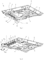
- the Fig. 1 shows a schematic perspective view of a gas hob 1.
- Die Fig. 2 shows a further schematic perspective view of the gas hob 1.
- the gas hob 1 can be a household cooking appliance or part of a household cooking appliance.
- the gas hob 1 can have several in the 1 and 2 Have gas burners, not shown.
- the gas hob 1 further comprises a hob pan 2, which is preferably made of a metal sheet.
- the hob pan 2 has a base 3, two side walls 4, 5 arranged opposite one another, a rear wall 6 and a front wall 7.
- the gas burners can be arranged in the cooktop pan 2 and one in the 1 and 2 Stand out cover plate, not shown, or a so-called top sheet.
- the gas hob 1 also has at least one gas valve 8 to 11.
- the number of gas valves 8 to 11 is arbitrary.
- a gas valve 8 to 11 is assigned to each gas burner.
- the gas valves 8 to 11 are arranged adjacent to the front wall 7.
- the gas valves 8 to 11 are set up to regulate or shut off a fuel gas flow from a main gas line 12 of the gas hob 1 to a gas burner assigned to the respective gas valve 8 to 11.
- the gas valves 8 to 11 can be designed as stepless gas valves or as stepped gas valves, so-called step valves.
- the gas valves 8 to 11 are preferably clamped to the main gas line 12.
- the gas hob 1 further comprises a main gas line arrangement 13, which comprises the main gas line 12 and a connecting piece 14.
- the main gas line arrangement 13 further comprises a union nut 15 for connecting the main gas line 12 to the connecting piece 14.
- the main gas line 12 is led from outside the cooktop pan 2 through an opening into the interior of the cooktop pan 2.
- the preferably angular connector 14 can be screwed into the union nut 15 by a rotary movement.
- the connector 14 can be held and the union nut 15 screwed onto the connector 14.
- a torque M 14 is applied to the connector 14.
- the main gas line arrangement 13 is set up to reduce the torque M 14 , in particular not to transmit it to the main gas line 12.
- When mounting the connector 14 is on the Main gas line 12 transmit a maximum torque M 12 , which is significantly smaller than the torque M 14 .
- the Fig. 3 shows the gas hob 1 in a sectional view. As the Fig. 3 shows, the gas valves 8 to 11 are clamped to the main gas line 12.
- the torque M 12 is smaller than the torque M 14 .
- the torque M 12 is preferably approximately or equal to zero.
- the Fig. 4 shows the main gas line arrangement 13 in a schematic exploded view.
- the main gas line arrangement 13 has, in addition to the main gas line 12, the angular connecting piece 14 and the union nut 15 for connecting the main gas line 12 to the connecting piece 14, a sealing washer 18 arranged between a flange 16 of the main gas line 12 and a flange 17 of the connecting piece 14.
- the sealing disk 18 is preferably made of a plastic material.
- the sealing disk 18 can be made on the basis of aramid fibers.
- the sealing disk 18 can be made from the material AFM 34 from Victor Reinz.
- the flange 16 of the main gas line 12 is preferably annular and completely surrounds an end section of the main gas line 12.
- the flange 17 of the connector 14 is preferably disc-shaped.
- the Fig. 5 shows the connector 14 in a schematic perspective view.
- the connector 14 has an external thread 19 in which the union nut 15 engages in a form-fitting manner.
- the connector 14 is preferably curved by 90 °.
- An end portion of the connector 14 is formed with a cone 20.
- a gas connection line can be pushed onto the cone 20.
- the main gas line 12 can be connected to a gas network using the gas connection line.
- a surface 25 ( Fig. 5 ) of the flange 17 of the connecting piece 14 is modified such that a frictional connection between the flange 17 of the connecting piece 14 and the sealing disk 18 is greater than a frictional connection between the sealing disk 18 and the flange 16 of the main gas line 12, so that the torque applied to the connecting piece 14 M 14 is not or only partially transferred from the sealing disk 18 to the flange 16 of the main gas line 12. That is, the sealing washer 18 slips on the flange 16 of the main gas line 12 while adhering to the flange 17 of the connector 14.
- the Fig. 6 shows the connector 14 in a schematic sectional view.
- the angled connector 14 has a horizontal length l 1 and a vertical length l 2 .
- the length l 1 is for example 27 mm
- the length l 2 is for example 33 mm.
- the cone 20 has a cone length l 3 .
- the cone length l 3 is, for example, 15 mm.
- the cone 20 has a taper c of half an inch according to ISO R7.
- the connector 14 also has a first section 26 with the length l 1 and a second section 27 with the length l 2 .
- the sections 26, 27 are tubular and are positioned perpendicular to each other.
- the first section 26 has a diameter d 1 .
- the second section 27 has a diameter d 2 .
- the diameters d 1 and d 2 are, for example, 16.5 mm.
- the external thread 19 of the connection piece 14 is, for example, a half-inch thread according to ISO 228.
- the flange 17 of the connection piece 14 has a width b 1 .
- the width b 1 is, for example, 2 mm.
- the external thread 19 and the flange 17 together have a width b 2 .
- the width b 2 is, for example, 8.6 mm.
- the flange 17 also has an inner diameter d 3 and an outer diameter d 4 .
- the inner diameter d 3 is, for example, 12.4 ⁇ 0.1 mm.
- the outer diameter d 4 is, for example, 18.4 ⁇ 0.1 mm.
- the surface 25 of the flange 17 of the connector 14 is modified so that the sealing washer 18 does not slip on the surface 25 when the union nut 15 is screwed onto the external thread 19.
- the surface 25 of the flange 17 has a lower limit value of Ra 5 and an upper limit value of Ra 10 of a medium roughness or center roughness Ra 17 .
- An end surface 28 of the cone 20 of the Connector 14 has a lower limit of a center roughness Ra 20 of Ra 5 and an upper limit of Ra 10.
- a center roughness Ra 17 of the flange 17 of the connecting piece 14 is preferably greater than a mean roughness Ra 16 of the flange 16 of the main gas line 12.
- the sealing disk 18 has two side surfaces 29, 30 ( Fig. 4 ), which have an identical center roughness Ra 18 , which is preferably smaller than the center roughness Ra 17 of the surface 25.
Landscapes
- Engineering & Computer Science (AREA)
- General Engineering & Computer Science (AREA)
- Mechanical Engineering (AREA)
- Chemical & Material Sciences (AREA)
- Combustion & Propulsion (AREA)
- Valve Housings (AREA)
- Feeding And Controlling Fuel (AREA)
- Flanged Joints, Insulating Joints, And Other Joints (AREA)
Description
- Die vorliegende Erfindung betrifft eine Gaskochstelle mit einer Hauptgasleitungsanordnung.
- Eine Gaskochstelle kann eine Kochmuldenwanne, eine in der Kochmuldenwanne angeordnete Hauptgasleitung und mehrere an der Hauptgasleitung befestigte Gasventile aufweisen, die dazu eingerichtet sind, einen Brenngasstrom von der Hauptgasleitung zu einem jeweiligen Gasbrenner der Gaskochstelle zu regeln oder zu unterbrechen. Beim Montieren einer Gasanschlussleitung an der Hauptgasleitung kann diese, um ein Verdrehen derselben zu verhindern, während der Montage mit einem Werkzeug wie beispielsweise einer Zange fixiert werden.
- Die
WO 2013/175350 A2 beschreibt ein gasbeheiztes Gargerät mit zumindest einem Gasventil, welches einen Anschluss aufweist, einer Gasleitung, welche mit dem Anschluss verbunden ist, um das Gasventil mit Gas zu versorgen, einem Gehäuseteil und einem Trägerteil, welches an dem Gehäuseteil befestigt ist und die Gasleitung relativ zu dem Anschluss fixiert. - Die
WO 99/14525 A1 - Vor diesem Hintergrund besteht eine Aufgabe der vorliegenden Erfindung darin, eine verbesserte Gaskochstelle mit einer Hauptgasleitungsanordnung zur Verfügung zu stellen.
- Demgemäß wird eine Gaskochstelle umfassend eine Hauptgasleitungsanordnung vorgeschlagen. Die Hauptgasleitungsanordnung umfasst eine Hauptgasleitung, ein Anschlussstück, eine zwischen einem Flansch der Hauptgasleitung und einem Flansch des Anschlussstücks angeordnete Dichtscheibe und eine Überwurfmutter zum Verbinden der Hauptgasleitung mit dem Anschlussstück, wobei sich ein Reibschluss zwischen dem Flansch des Anschlussstücks und der Dichtscheibe von einem Reibschluss zwischen der Dichtscheibe und dem Flansch der Hauptgasleitung derart unterscheidet, dass beim Aufbringen eines Drehmoments auf das Anschlussstück die Dichtscheibe auf dem Flansch der Hauptgasleitung derart gleitet, dass das Drehmoment reduziert auf den Flansch der Hauptgasleitung übertragen wird, und wobei das Anschlussstück ein Außengewinde aufweist, in das die Überwurfmutter formschlüssig eingreift.
- Dadurch, dass das Drehmoment nicht oder zumindest reduziert auf den Flansch der Hauptgasleitung übertragen wird, wird ein Verdrehen der Hauptgasleitung beim Montieren des Anschlussstücks relativ zu an der Hauptgasleitung befestigten Gasventilen verhindert. Hierdurch werden Undichtigkeiten zwischen der Hauptgasleitung und den Gasventilen verhindert. Weiterhin kann auf zusätzliches Werkzeug zum Fixieren der Hauptgasleitung verzichtet werden.
- Insbesondere umfasst die Hauptgasleitungsanordnung eine Hauptgasleitung, ein Anschlussstück, eine zwischen einem Flansch der Hauptgasleitung und einem Flansch des Anschlussstücks angeordnete Dichtscheibe und eine Überwurfmutter zum Verbinden der Hauptgasleitung mit dem Anschlussstück, wobei beim Aufbringen eines Drehmoments auf das Anschlussstück die Dichtscheibe auf dem Flansch der Hauptgasleitung derart gleitet, dass das Drehmoment reduziert auf den Flansch der Hauptgasleitung übertragen wird.
- Gemäß einer Ausführungsform gleitet beim Aufbringen eines Drehmoments auf das Anschlussstück die Dichtscheibe auf dem Flansch der Hauptgasleitung derart, dass das Drehmoment nicht auf den Flansch der Hauptgasleitung übertragen wird.
- Das Drehmoment wird vorzugsweise auf null reduziert.
- Gemäß einer weiteren Ausführungsform ist eine Oberfläche des Flansches des Anschlussstücks so modifiziert, dass ein Reibschluss zwischen dem Flansch des Anschlussstücks und der Dichtscheibe größer als ein Reibschluss zwischen der Dichtscheibe und dem Flansch der Hauptgasleitung ist, so dass das auf das Anschlussstück aufgebrachte Drehmoment von der Dichtscheibe reduziert, insbesondere nicht, auf den Flansch der Hauptgasleitung übertragen wird.
- Vorzugsweise weist die Oberfläche des Flansches des Anschlussstücks eine mittlere Rauheit von Ra 5 bis Ra 10 auf. Die Oberfläche ist vorzugsweise scheibenförmig. Insbesondere ist die Rauheit der Oberfläche des Flansches des Anschlussstücks so groß, dass die Dichtscheibe auf der Oberfläche des Flansches des Anschlussstücks haftet. Gemäß einer weiteren Ausführungsform ist die Dichtscheibe aus einem Kunststoffmaterial gefertigt.
- Insbesondere kann die Dichtscheibe aus einem Aramidgewebe gefertigt sein.
- Gemäß einer weiteren Ausführungsform ist die mittlere Rauheit des Flansches des Anschlussstücks größer als die mittlere Rauheit des Flansches der Hauptgasleitung.
- Der Flansch der Hauptgasleitung ist vorzugsweise ringförmig und umläuft ein Ende der Hauptgasleitung vollständig. Insbesondere ist der Flansch der Hauptgasleitung nicht modifiziert. Das heißt, die Hauptgasleitung ist ein Standardbauteil.
- Gemäß einer weiteren Ausführungsform weist die Dichtscheibe zwei Seitenflächen auf, die die gleiche mittlere Rauheit aufweisen.
- Die Dichtscheibe ist vorzugsweise dazu eingerichtet, das Anschlussstück gegenüber der Hauptgasleitung gasdicht abzudichten.
- Gemäß einer weiteren Ausführungsform weisen die zwei Seitenflächen der Dichtscheibe eine kleinere mittlere Rauheit auf als der Flansch des Anschlussstücks.
- Gemäß einer weiteren Ausführungsform ist das Anschlussstück um 90° gekrümmt.
- Das Anschlussstück weist vorzugsweise einen ersten Abschnitt und einen zweiten Abschnitt auf, die senkrecht zueinander angeordnet sind. An dem ersten Abschnitt ist vorzugsweise der Flansch vorgesehen. An dem zweiten Abschnitt ist vorzugsweise ein Konus vorgesehen. Auf den Konus kann eine Gasanschlussleitung zum Anschließen der Hauptgasleitung an ein Gasnetz aufgesteckt werden. Eine Oberfläche oder Stirnfläche des Konus ist vorzugsweise wie die Oberfläche des Flansches des Anschlussstücks modifiziert.
- Gemäß einer weiteren Ausführungsform sind an der Hauptgasleitung Gasventile angeordnet.
- Die Hauptgasleitungsanordnung kann die Gasventile umfassen. Die Gasventile können stufenlos regelbar oder sogenannte Step Valves sein. Die Gasventile sind vorzugsweise an die Hauptgasleitung angeklemmt.
- Gemäß einer weiteren Ausführungsform hintergreift die Überwurfmutter den Flansch der Hauptgasleitung.
- Insbesondere hintergreift die Überwurfmutter den Flansch der Hauptgasleitung formschlüssig.
- Die Gaskochstelle kann ein Haushaltsgargerät oder ein Teil eines Haushaltsgargeräts sein.
- Weitere vorteilhafte Ausgestaltungen und Aspekte der Gaskochstelle sind Gegenstand der Unteransprüche sowie der im Folgenden beschriebenen Ausführungsbeispiele der Gaskochstelle. Im Weiteren werden die Hauptgasleitungsanordnung und/oder die Gaskochstelle anhand von bevorzugten Ausführungsformen unter Bezugnahme auf die beigelegten Figuren näher erläutert.
-
Fig. 1 zeigt eine schematische perspektivische Ansicht einer Ausführungsform einer Gaskochstelle; -
Fig. 2 zeigt eine weitere schematische perspektivische Ansicht der Gaskochstelle; -
Fig. 3 zeigt eine schematische Schnittansicht der Gaskochstelle gemäß derFig. 1 ; -
Fig. 4 zeigt eine schematische Explosionsansicht einer Ausführungsform einer Hauptgasleitungsanordnung für die Gaskochstelle gemäß derFig. 1 ; -
Fig. 5 zeigt eine schematische perspektivische Ansicht einer Ausführungsform eines Anschlussstücks für die Hauptgasleitungsanordnung gemäß derFig. 4 ; und -
Fig. 6 zeigt eine schematische Schnittansicht des Anschlussstücks gemäß derFig. 5 . - In den Figuren sind gleiche oder funktionsgleiche Elemente mit denselben Bezugszeichen versehen worden, sofern nichts anderes angegeben ist.
- Die
Fig. 1 zeigt eine schematische perspektivische Ansicht einer Gaskochstelle 1. DieFig. 2 zeigt eine weitere schematische perspektivische Ansicht der Gaskochstelle 1. Die Gaskochstelle 1 kann ein Haushaltsgargerät oder ein Teil eines Haushaltsgargerätes sein. Die Gaskochstelle 1 kann mehrere in denFig. 1 und 2 nicht gezeigte Gasbrenner aufweisen. - Die Gaskochstelle 1 umfasst ferner eine Kochmuldenwanne 2, welche vorzugsweise aus einem Metallblech gefertigt ist. Die Kochmuldenwanne 2 weist einen Boden 3, zwei einander gegenüberliegend angeordnete Seitenwände 4, 5, eine Rückwand 6 und eine Vorderwand 7 auf. Die Gasbrenner können in der Kochmuldenwanne 2 angeordnet sein und über eine in den
Fig. 1 und 2 nicht gezeigte Deckplatte oder ein sogenanntes Top Sheet herausragen. - Die Gaskochstelle 1 weist weiterhin zumindest ein Gasventil 8 bis 11 auf. Die Anzahl der Gasventile 8 bis 11 ist beliebig. Jedem Gasbrenner ist ein Gasventil 8 bis 11 zugeordnet. Die Gasventile 8 bis 11 sind benachbart zu der Vorderwand 7 angeordnet. Die Gasventile 8 bis 11 sind dazu eingerichtet, einen Brenngasstrom von einer Hauptgasleitung 12 der Gaskochstelle 1 zu einem dem jeweiligen Gasventil 8 bis 11 zugeordneten Gasbrenner zu regeln oder abzusperren. Die Gasventile 8 bis 11 können als stufenlose Gasventile oder als gestufte Gasventile, als sogenannte Step Valves, ausgebildet sein. Die Gasventile 8 bis 11 sind vorzugsweise an die Hauptgasleitung 12 angeklemmt.
- Die Gaskochstelle 1 umfasst weiterhin eine Hauptgasleitungsanordnung 13, die die Hauptgasleitung 12 und ein Anschlussstück 14 umfasst. Die Hauptgasleitungsanordnung 13 umfasst weiterhin eine Überwurfmutter 15 zum Verbinden der Hauptgasleitung 12 mit dem Anschlussstück 14. Die Hauptgasleitung 12 wird von außerhalb der Kochmuldenwanne 2 durch einen Durchbruch in das Innere der Kochmuldenwanne 2 geführt. Das vorzugsweise winkelförmige Anschlussstück 14 kann durch eine Drehbewegung in die Überwurfmutter 15 eingeschraubt werden. Alternativ kann das Anschlussstück 14 festgehalten und die Überwurfmutter 15 auf das Anschlussstück 14 aufgeschraubt werden. Hierbei wird auf das Anschlussstück 14 ein Drehmoment M14 aufgebracht. Die Hauptgasleitungsanordnung 13 ist dazu eingerichtet, das Drehmoment M14 zu reduzieren, insbesondere nicht auf die Hauptgasleitung 12 zu übertragen. Beim Montieren des Anschlussstücks 14 wird auf die Hauptgasleitung 12 maximal ein Drehmoment M12 übertragen, das deutlich kleiner als das Drehmoment M14 ist.
- Die
Fig. 3 zeigt die Gaskochstelle 1 in einer Schnittansicht. Wie dieFig. 3 zeigt, sind die Gasventile 8 bis 11 an die Hauptgasleitung 12 angeklemmt. Das Drehmoment M12 ist dabei kleiner als das Drehmoment M14. Vorzugsweise ist das Drehmoment M12 annähernd oder gleich Null. - Die
Fig. 4 zeigt die Hauptgasleitungsanordnung 13 in einer schematischen Explosionsansicht. Die Hauptgasleitungsanordnung 13 weist neben der Hauptgasleitung 12, dem winkelförmigen Anschlussstück 14 und der Überwurfmutter 15 zum Verbinden der Hauptgasleitung 12 mit dem Anschlussstück 14 eine zwischen einem Flansch 16 der Hauptgasleitung 12 und einem Flansch 17 des Anschlussstücks 14 angeordnete Dichtscheibe 18 auf. Die Dichtscheibe 18 ist vorzugsweise aus einem Kunststoffmaterial gefertigt. Beispielsweise kann die Dichtscheibe 18 auf Basis von Aramidfasern gefertigt sein. Insbesondere kann die Dichtscheibe 18 aus dem Material AFM 34 der Firma Victor Reinz gefertigt sein. Der Flansch 16 der Hauptgasleitung 12 ist vorzugsweise ringförmig und umläuft einen Endabschnitt der Hauptgasleitung 12 vollständig. Der Flansch 17 des Anschlussstücks 14 ist vorzugsweise scheibenförmig. - Die
Fig. 5 zeigt das Anschlussstück 14 in einer schematischen perspektivischen Ansicht. Das Anschlussstück 14 weist ein Außengewinde 19 auf, in das die Überwurfmutter 15 formschlüssig eingreift. Das Anschlussstück 14 ist vorzugsweise um 90° gekrümmt. Ein Endabschnitt des Anschlussstücks 14 ist mit einem Konus 20 ausgebildet. Auf dem Konus 20 kann eine Gasanschlussleitung aufgeschoben werden. Mit Hilfe der Gasanschlussleitung ist die Hauptgasleitung 12 an ein Gasnetz anschließbar. - Beim Aufbringen des Drehmoments M14 auf das Anschlussstück 14 gleitet die Dichtscheibe 18 auf dem Flansch 16 der Hauptgasleitung 12 derart, dass das Drehmoment M14 reduziert, insbesondere nicht auf den Flansch 16 der Hauptgasleitung 12 übertragen, wird. Hierdurch wird beim Einschrauben des Anschlussstücks 14 in die Überwurfmutter 15 bzw. beim Aufschrauben der Überwurfmutter 15 auf das Außengewinde 19 des Anschlussstücks 14 kein oder nur ein geringes Drehmoment M12 auf die Hauptgasleitung 12 übertragen. Hierdurch werden Undichtigkeiten der Klemmverbindung der Gasventile 8 bis 11 mit der Hauptgasleitung 12 verhindert, da eine Relativbewegung der Hauptgasleitung 12 relativ zu den Gasventilen 8 bis 11 unterbunden wird. Zum Anklemmen der Gasventile 8 bis 11 an die Hauptgasleitung 12 sind an dieser Bohrungen 21 bis 24 vorgesehen.
- Insbesondere ist eine Oberfläche 25 (
Fig. 5 ) des Flansches 17 des Anschlussstücks 14 so modifiziert, dass ein Reibschluss zwischen dem Flansch 17 des Anschlussstücks 14 und der Dichtscheibe 18 größer als ein Reibschluss zwischen der Dichtscheibe 18 und dem Flansch 16 der Hauptgasleitung 12 ist, so dass das auf das Anschlussstück 14 aufgebrachte Drehmoment M14 von der Dichtscheibe 18 nicht oder nur teilweise auf den Flansch 16 der Hauptgasleitung 12 übertragen wird. Das heißt, die Dichtscheibe 18 rutscht auf dem Flansch 16 der Hauptgasleitung 12, während sie auf dem Flansch 17 des Anschlussstücks 14 haftet. - Die
Fig. 6 zeigt das Anschlussstück 14 in einer schematischen Schnittansicht. Das gewinkelte Anschlussstück 14 weist eine horizontale Länge l1 und eine vertikale Länge l2 auf. Die Länge l1 beträgt beispielsweise 27 mm, die Länge l2 beträgt beispielsweise 33 mm. Der Konus 20 weist eine Konuslänge l3 auf. Die Konuslänge l3 beträgt beispielsweise 15 mm. Der Konus 20 weist nach ISO R7 eine Konizität c von einem halben Zoll auf. Das Anschlussstück 14 weist ferner einen ersten Abschnitt 26 mit der Länge l1 und einen zweiten Abschnitt 27 mit der Länge l2 auf. Die Abschnitte 26, 27 sind rohrförmig und sind senkrecht zueinander positioniert. Der erste Abschnitt 26 weist einen Durchmesser d1 auf. Der zweite Abschnitt 27 weist einen Durchmesser d2 auf. Die Durchmesser d1 und d2 betragen beispielsweise 16,5 mm. - Das Außengewinde 19 des Anschlussstücks 14 ist beispielsweise ein Halbzollgewinde nach ISO 228. Der Flansch 17 des Anschlussstücks 14 weist eine Breite b1 auf. Die Breite b1 beträgt beispielsweise 2 mm. Das Außengewinde 19 und der Flansch 17 zusammen weisen eine Breite b2 auf. Die Breite b2 beträgt beispielsweise 8,6 mm. Der Flansch 17 weist weiterhin einen Innendurchmesser d3 und einen Außendurchmesser d4 auf. Der Innendurchmesser d3 beträgt beispielsweise 12,4 ± 0,1 mm. Der Außendurchmesser d4 beträgt beispielsweise 18,4 ± 0,1 mm.
- Die Oberfläche 25 des Flansches 17 des Anschlussstücks 14 ist so modifiziert, dass die Dichtscheibe 18 beim Aufschrauben der Überwurfmutter 15 auf das Außengewinde 19 nicht auf der Oberfläche 25 abrutscht. Beispielsweise weist die Oberfläche 25 des Flansches 17 einen unteren Grenzwert von Ra 5 und einen oberen Grenzwert von Ra 10 einer mittleren Rauheit oder Mittenrauheit Ra17 auf. Auch eine endseitige Oberfläche 28 des Konus 20 des Anschlussstücks 14 weist einen unteren Grenzwert einer Mittenrauheit Ra20 von Ra 5 und einen oberen Grenzwert von Ra 10 auf. Vorzugsweise ist eine Mittenrauheit Ra17 des Flansches 17 des Anschlussstücks 14 größer als eine mittlere Rauheit Ra16 des Flansches 16 der Hauptgasleitung 12. Die Dichtscheibe 18 weist zwei Seitenflächen 29, 30 (
Fig. 4 ) auf, die eine identische Mittenrauheit Ra18 aufweisen, die vorzugsweise kleiner ist als die Mittenrauheit Ra17 der Oberfläche 25. -
- 1
- Gaskochstelle
- 2
- Kochmuldenwanne
- 3
- Boden
- 4
- Seitenwand
- 5
- Seitenwand
- 6
- Rückwand
- 7
- Vorderwand
- 8
- Gasventil
- 9
- Gasventil
- 10
- Gasventil
- 11
- Gasventil
- 12
- Hauptgasleitung
- 13
- Hauptgasleitungsanordnung
- 14
- Anschlussstück
- 15
- Überwurfmutter
- 16
- Flansch
- 17
- Flansch
- 18
- Dichtscheibe
- 19
- Außengewinde
- 20
- Konus
- 21
- Bohrung
- 22
- Bohrung
- 23
- Bohrung
- 24
- Bohrung
- 25
- Oberfläche
- 26
- Abschnitt
- 27
- Abschnitt
- 28
- Oberfläche
- 29
- Seitenfläche
- 30
- Seitenfläche
- b1
- Breite
- b2
- Breite
- c
- Konizität
- d1
- Durchmesser
- d2
- Durchmesser
- d3
- Durchmesser
- d4
- Durchmesser
- l1
- Länge
- l2
- Länge
- l3
- Länge
- M12
- Drehmoment
- M14
- Drehmoment
- Ra16
- mittlere Rauheit
- Ra17
- mittlere Rauheit
- Ra20
- mittlere Rauheit
Claims (10)
- Gaskochstelle (1) umfassend eine Hauptgasleitungsanordnung (13) mit einer Hauptgasleitung (12), einem Anschlussstück (14), einer zwischen einem Flansch (16) der Hauptgasleitung (12) und einem Flansch (17) des Anschlussstücks (14) angeordneten Dichtscheibe (18) und einer Überwurfmutter (15) zum Verbinden der Hauptgasleitung (12) mit dem Anschlussstück (14), wobei sich ein Reibschluss zwischen dem Flansch (17) des Anschlussstücks (14) und der Dichtscheibe (18) von einem Reibschluss zwischen der Dichtscheibe (18) und dem Flansch (16) der Hauptgasleitung (12) derart unterscheidet, dass beim Aufbringen eines Drehmoments (M14) auf das Anschlussstück (14) die Dichtscheibe (18) auf dem Flansch (16) der Hauptgasleitung (12) derart gleitet, dass das Drehmoment (M14) reduziert auf den Flansch (16) der Hauptgasleitung (12) übertragen wird, und wobei das Anschlussstück (14) ein Außengewinde (19) aufweist, in das die Überwurfmutter (15) formschlüssig eingreift.
- Gaskochstelle nach Anspruch 1, dadurch gekennzeichnet, dass beim Aufbringen eines Drehmoments (M14) auf das Anschlussstück (14) die Dichtscheibe (18) auf dem Flansch (16) der Hauptgasleitung (12) derart gleitet, dass das Drehmoment (M14) nicht auf den Flansch (16) der Hauptgasleitung (12) übertragen wird.
- Gaskochstelle nach Anspruch 1 oder 2, dadurch gekennzeichnet, dass eine Oberfläche (25) des Flansches (17) des Anschlussstücks (14) so modifiziert ist, dass der Reibschluss zwischen dem Flansch (17) des Anschlussstücks (14) und der Dichtscheibe (18) größer als der Reibschluss zwischen der Dichtscheibe (18) und dem Flansch (16) der Hauptgasleitung (12) ist, so dass das auf das Anschlussstück (14) aufgebrachte Drehmoment (M14) von der Dichtscheibe (18) reduziert auf den Flansch (16) der Hauptgasleitung (12) übertragen wird.
- Gaskochstelle nach einem der Ansprüche 1 - 3, dadurch gekennzeichnet, dass die Dichtscheibe (18) aus einem Kunststoffmaterial gefertigt ist.
- Gaskochstelle nach einem der Ansprüche 1 - 4, dadurch gekennzeichnet, dass die mittlere Rauheit (Ra17) des Flansches (17) des Anschlussstücks (14) größer als die mittlere Rauheit (Ra16) des Flansches (16) der Hauptgasleitung (12) ist.
- Gaskochstelle nach einem der Ansprüche 1 - 5, dadurch gekennzeichnet, dass die Dichtscheibe (18) zwei Seitenflächen (29, 30) aufweist, die die gleiche mittlere Rauheit (Ra18) aufweisen.
- Gaskochstelle nach Anspruch 6, dadurch gekennzeichnet, dass die zwei Seitenflächen (29, 30) der Dichtscheibe (18) eine kleinere mittlere Rauheit (Ra18) aufweisen als der Flansch (17) des Anschlussstücks (14).
- Gaskochstelle nach einem der Ansprüche 1 - 7, dadurch gekennzeichnet, dass das Anschlussstück (14) um 90° gekrümmt ist.
- Gaskochstelle nach einem der Ansprüche 1 - 8, dadurch gekennzeichnet, dass an der Hauptgasleitung (12) Gasventile (8 -11) angeordnet sind.
- Gaskochstelle nach einem der Ansprüche 1 - 9, dadurch gekennzeichnet, dass die Überwurfmutter (15) den Flansch (16) der Hauptgasleitung (12) hintergreift.
Applications Claiming Priority (2)
| Application Number | Priority Date | Filing Date | Title |
|---|---|---|---|
| ES201530433A ES2584917B1 (es) | 2015-03-31 | 2015-03-31 | Disposición de conducto principal de gas y punto de cocción a gas |
| PCT/IB2016/051162 WO2016157004A1 (de) | 2015-03-31 | 2016-03-02 | Hauptgasleitungsanordnung und gaskochstelle |
Publications (2)
| Publication Number | Publication Date |
|---|---|
| EP3277996A1 EP3277996A1 (de) | 2018-02-07 |
| EP3277996B1 true EP3277996B1 (de) | 2020-01-29 |
Family
ID=55524405
Family Applications (1)
| Application Number | Title | Priority Date | Filing Date |
|---|---|---|---|
| EP16709595.9A Active EP3277996B1 (de) | 2015-03-31 | 2016-03-02 | Gaskochstelle mit hauptgasleitungsanordnung |
Country Status (3)
| Country | Link |
|---|---|
| EP (1) | EP3277996B1 (de) |
| ES (1) | ES2584917B1 (de) |
| WO (1) | WO2016157004A1 (de) |
Cited By (1)
| Publication number | Priority date | Publication date | Assignee | Title |
|---|---|---|---|---|
| EP4703640A1 (de) * | 2024-09-03 | 2026-03-04 | BSH Hausgeräte GmbH | Gaskochgerät mit gaseinlassverbinder |
Family Cites Families (9)
| Publication number | Priority date | Publication date | Assignee | Title |
|---|---|---|---|---|
| DE4141841C1 (en) * | 1991-12-18 | 1993-03-11 | R. Woeste & Co Gmbh & Co Kg, 4000 Duesseldorf, De | Threaded coupling for gas fittings - has second threaded section corresp. to counter thread on bush for form-fitting connection |
| US6623047B2 (en) * | 1997-06-16 | 2003-09-23 | Swagelok Company | Tube coupling |
| US6318766B1 (en) * | 1997-09-15 | 2001-11-20 | Swagelok Company | Face seal gland with raised peripheral ring having circumferentially spaced recesses |
| FI111985B (fi) * | 2000-11-09 | 2003-10-15 | Marioff Corp Oy | Putkiliitos |
| DE502004008971D1 (de) * | 2004-08-03 | 2009-03-26 | Ti Automotive Heidelberg Gmbh | Rohranschlusseinrichtung |
| DE202007016637U1 (de) * | 2007-11-27 | 2009-04-09 | Tube Technology Systems Ag | Rohrverbindung |
| JP5202555B2 (ja) * | 2010-02-18 | 2013-06-05 | Ckd株式会社 | ポート構造及びポート構造を備える流体機器 |
| ES2430939R1 (es) * | 2012-05-22 | 2014-03-03 | BSH Electrodomésticos España S.A. | Aparato de cocción calentado a gas |
| GB2503561B (en) * | 2013-05-08 | 2014-09-10 | Verderg Connectors Ltd | Plug for subsea components |
-
2015
- 2015-03-31 ES ES201530433A patent/ES2584917B1/es not_active Expired - Fee Related
-
2016
- 2016-03-02 EP EP16709595.9A patent/EP3277996B1/de active Active
- 2016-03-02 WO PCT/IB2016/051162 patent/WO2016157004A1/de not_active Ceased
Non-Patent Citations (1)
| Title |
|---|
| None * |
Cited By (1)
| Publication number | Priority date | Publication date | Assignee | Title |
|---|---|---|---|---|
| EP4703640A1 (de) * | 2024-09-03 | 2026-03-04 | BSH Hausgeräte GmbH | Gaskochgerät mit gaseinlassverbinder |
Also Published As
| Publication number | Publication date |
|---|---|
| ES2584917A1 (es) | 2016-09-30 |
| WO2016157004A1 (de) | 2016-10-06 |
| ES2584917B1 (es) | 2017-09-25 |
| EP3277996A1 (de) | 2018-02-07 |
Similar Documents
| Publication | Publication Date | Title |
|---|---|---|
| DE2022907C3 (de) | Schraube mit einem in einer Kunst stoffkappe eingebetteten Kopf | |
| EP0379496B1 (de) | Rohrverbindung zur bildung eines knotenpunktes | |
| DE2241521B2 (de) | ||
| DE202007008643U1 (de) | Verschraubungselement | |
| EP3134671A1 (de) | Schlauchkupplung | |
| EP3277996B1 (de) | Gaskochstelle mit hauptgasleitungsanordnung | |
| DE19529189C2 (de) | Anschlußstück | |
| DE102016004978A1 (de) | Drehkupplung mit Kabelkanal und Drehwinkelbegrenzung | |
| DE2527132B2 (de) | AnschluBvorrichtung für einen Heizkörper | |
| EP3557108B9 (de) | Anschlussvorrichtung für medienleitungen | |
| EP1464899B1 (de) | Dichtsystem für einen Heizkörper | |
| EP0039476B1 (de) | Vorrichtung zum Anschluss eines Heizkörperventils, insbesondere Thermostatventils, an einen Heizkörper | |
| DE102015217914A1 (de) | Schalthebelanbindung | |
| DE29600241U1 (de) | Lösbare Rohrverbindung für Kunststoffrohre | |
| EP3184911A1 (de) | Höhenverstellungsvorrichtung | |
| DE1550468B2 (de) | Doppelsitzventil | |
| WO2016198553A1 (de) | Montagevorrichtung für ein armaturenpaneel | |
| DE102007004717B3 (de) | Anschlussarmatur für eine flüssigkeitsführende Anordnung, insbesondere eine Heizkörperanordnung | |
| EP0759487A1 (de) | Anschlussstück | |
| DE102016118121A1 (de) | Werkzeugmaschine und Verfahren zur Bearbeitung eines Werkstücks mit einer Werkzeugmaschine | |
| DE3145380C2 (de) | Schweißmuffe an einer Vorrichtung zum Verbinden der Zulaufkanäle eines Zweiplattenheizkörpers | |
| DE19533648C2 (de) | Rohrkupplung | |
| EP3096085A1 (de) | Haushaltsgeräte-bedienanordnung, gasventil und gaskochstelle | |
| DE69917086T2 (de) | Gaskochbrenner mit Bajonettkupplung | |
| EP3196527A1 (de) | Stützanordnung |
Legal Events
| Date | Code | Title | Description |
|---|---|---|---|
| STAA | Information on the status of an ep patent application or granted ep patent |
Free format text: STATUS: THE INTERNATIONAL PUBLICATION HAS BEEN MADE |
|
| PUAI | Public reference made under article 153(3) epc to a published international application that has entered the european phase |
Free format text: ORIGINAL CODE: 0009012 |
|
| STAA | Information on the status of an ep patent application or granted ep patent |
Free format text: STATUS: REQUEST FOR EXAMINATION WAS MADE |
|
| 17P | Request for examination filed |
Effective date: 20171102 |
|
| AK | Designated contracting states |
Kind code of ref document: A1 Designated state(s): AL AT BE BG CH CY CZ DE DK EE ES FI FR GB GR HR HU IE IS IT LI LT LU LV MC MK MT NL NO PL PT RO RS SE SI SK SM TR |
|
| AX | Request for extension of the european patent |
Extension state: BA ME |
|
| DAV | Request for validation of the european patent (deleted) | ||
| DAX | Request for extension of the european patent (deleted) | ||
| STAA | Information on the status of an ep patent application or granted ep patent |
Free format text: STATUS: EXAMINATION IS IN PROGRESS |
|
| 17Q | First examination report despatched |
Effective date: 20181113 |
|
| RIC1 | Information provided on ipc code assigned before grant |
Ipc: F24C 3/00 20060101ALI20190717BHEP Ipc: F16L 19/025 20060101ALI20190717BHEP Ipc: F16L 19/02 20060101AFI20190717BHEP Ipc: F24C 3/08 20060101ALI20190717BHEP |
|
| GRAP | Despatch of communication of intention to grant a patent |
Free format text: ORIGINAL CODE: EPIDOSNIGR1 |
|
| STAA | Information on the status of an ep patent application or granted ep patent |
Free format text: STATUS: GRANT OF PATENT IS INTENDED |
|
| INTG | Intention to grant announced |
Effective date: 20190827 |
|
| GRAS | Grant fee paid |
Free format text: ORIGINAL CODE: EPIDOSNIGR3 |
|
| GRAA | (expected) grant |
Free format text: ORIGINAL CODE: 0009210 |
|
| STAA | Information on the status of an ep patent application or granted ep patent |
Free format text: STATUS: THE PATENT HAS BEEN GRANTED |
|
| AK | Designated contracting states |
Kind code of ref document: B1 Designated state(s): AL AT BE BG CH CY CZ DE DK EE ES FI FR GB GR HR HU IE IS IT LI LT LU LV MC MK MT NL NO PL PT RO RS SE SI SK SM TR |
|
| REG | Reference to a national code |
Ref country code: GB Ref legal event code: FG4D Free format text: NOT ENGLISH |
|
| REG | Reference to a national code |
Ref country code: CH Ref legal event code: EP |
|
| REG | Reference to a national code |
Ref country code: AT Ref legal event code: REF Ref document number: 1228745 Country of ref document: AT Kind code of ref document: T Effective date: 20200215 |
|
| REG | Reference to a national code |
Ref country code: IE Ref legal event code: FG4D Free format text: LANGUAGE OF EP DOCUMENT: GERMAN |
|
| REG | Reference to a national code |
Ref country code: DE Ref legal event code: R096 Ref document number: 502016008531 Country of ref document: DE |
|
| REG | Reference to a national code |
Ref country code: NL Ref legal event code: MP Effective date: 20200129 |
|
| PG25 | Lapsed in a contracting state [announced via postgrant information from national office to epo] |
Ref country code: FI Free format text: LAPSE BECAUSE OF FAILURE TO SUBMIT A TRANSLATION OF THE DESCRIPTION OR TO PAY THE FEE WITHIN THE PRESCRIBED TIME-LIMIT Effective date: 20200129 Ref country code: NO Free format text: LAPSE BECAUSE OF FAILURE TO SUBMIT A TRANSLATION OF THE DESCRIPTION OR TO PAY THE FEE WITHIN THE PRESCRIBED TIME-LIMIT Effective date: 20200429 Ref country code: RS Free format text: LAPSE BECAUSE OF FAILURE TO SUBMIT A TRANSLATION OF THE DESCRIPTION OR TO PAY THE FEE WITHIN THE PRESCRIBED TIME-LIMIT Effective date: 20200129 Ref country code: PT Free format text: LAPSE BECAUSE OF FAILURE TO SUBMIT A TRANSLATION OF THE DESCRIPTION OR TO PAY THE FEE WITHIN THE PRESCRIBED TIME-LIMIT Effective date: 20200621 |
|
| REG | Reference to a national code |
Ref country code: LT Ref legal event code: MG4D |
|
| PG25 | Lapsed in a contracting state [announced via postgrant information from national office to epo] |
Ref country code: BG Free format text: LAPSE BECAUSE OF FAILURE TO SUBMIT A TRANSLATION OF THE DESCRIPTION OR TO PAY THE FEE WITHIN THE PRESCRIBED TIME-LIMIT Effective date: 20200429 Ref country code: IS Free format text: LAPSE BECAUSE OF FAILURE TO SUBMIT A TRANSLATION OF THE DESCRIPTION OR TO PAY THE FEE WITHIN THE PRESCRIBED TIME-LIMIT Effective date: 20200529 Ref country code: GR Free format text: LAPSE BECAUSE OF FAILURE TO SUBMIT A TRANSLATION OF THE DESCRIPTION OR TO PAY THE FEE WITHIN THE PRESCRIBED TIME-LIMIT Effective date: 20200430 Ref country code: LV Free format text: LAPSE BECAUSE OF FAILURE TO SUBMIT A TRANSLATION OF THE DESCRIPTION OR TO PAY THE FEE WITHIN THE PRESCRIBED TIME-LIMIT Effective date: 20200129 Ref country code: SE Free format text: LAPSE BECAUSE OF FAILURE TO SUBMIT A TRANSLATION OF THE DESCRIPTION OR TO PAY THE FEE WITHIN THE PRESCRIBED TIME-LIMIT Effective date: 20200129 Ref country code: HR Free format text: LAPSE BECAUSE OF FAILURE TO SUBMIT A TRANSLATION OF THE DESCRIPTION OR TO PAY THE FEE WITHIN THE PRESCRIBED TIME-LIMIT Effective date: 20200129 |
|
| PG25 | Lapsed in a contracting state [announced via postgrant information from national office to epo] |
Ref country code: NL Free format text: LAPSE BECAUSE OF FAILURE TO SUBMIT A TRANSLATION OF THE DESCRIPTION OR TO PAY THE FEE WITHIN THE PRESCRIBED TIME-LIMIT Effective date: 20200129 |
|
| REG | Reference to a national code |
Ref country code: DE Ref legal event code: R119 Ref document number: 502016008531 Country of ref document: DE |
|
| PG25 | Lapsed in a contracting state [announced via postgrant information from national office to epo] |
Ref country code: ES Free format text: LAPSE BECAUSE OF FAILURE TO SUBMIT A TRANSLATION OF THE DESCRIPTION OR TO PAY THE FEE WITHIN THE PRESCRIBED TIME-LIMIT Effective date: 20200129 Ref country code: MC Free format text: LAPSE BECAUSE OF FAILURE TO SUBMIT A TRANSLATION OF THE DESCRIPTION OR TO PAY THE FEE WITHIN THE PRESCRIBED TIME-LIMIT Effective date: 20200129 Ref country code: DK Free format text: LAPSE BECAUSE OF FAILURE TO SUBMIT A TRANSLATION OF THE DESCRIPTION OR TO PAY THE FEE WITHIN THE PRESCRIBED TIME-LIMIT Effective date: 20200129 Ref country code: SK Free format text: LAPSE BECAUSE OF FAILURE TO SUBMIT A TRANSLATION OF THE DESCRIPTION OR TO PAY THE FEE WITHIN THE PRESCRIBED TIME-LIMIT Effective date: 20200129 Ref country code: EE Free format text: LAPSE BECAUSE OF FAILURE TO SUBMIT A TRANSLATION OF THE DESCRIPTION OR TO PAY THE FEE WITHIN THE PRESCRIBED TIME-LIMIT Effective date: 20200129 Ref country code: SM Free format text: LAPSE BECAUSE OF FAILURE TO SUBMIT A TRANSLATION OF THE DESCRIPTION OR TO PAY THE FEE WITHIN THE PRESCRIBED TIME-LIMIT Effective date: 20200129 Ref country code: LT Free format text: LAPSE BECAUSE OF FAILURE TO SUBMIT A TRANSLATION OF THE DESCRIPTION OR TO PAY THE FEE WITHIN THE PRESCRIBED TIME-LIMIT Effective date: 20200129 Ref country code: RO Free format text: LAPSE BECAUSE OF FAILURE TO SUBMIT A TRANSLATION OF THE DESCRIPTION OR TO PAY THE FEE WITHIN THE PRESCRIBED TIME-LIMIT Effective date: 20200129 Ref country code: CZ Free format text: LAPSE BECAUSE OF FAILURE TO SUBMIT A TRANSLATION OF THE DESCRIPTION OR TO PAY THE FEE WITHIN THE PRESCRIBED TIME-LIMIT Effective date: 20200129 |
|
| REG | Reference to a national code |
Ref country code: CH Ref legal event code: PL |
|
| PLBE | No opposition filed within time limit |
Free format text: ORIGINAL CODE: 0009261 |
|
| STAA | Information on the status of an ep patent application or granted ep patent |
Free format text: STATUS: NO OPPOSITION FILED WITHIN TIME LIMIT |
|
| REG | Reference to a national code |
Ref country code: BE Ref legal event code: MM Effective date: 20200331 |
|
| PG25 | Lapsed in a contracting state [announced via postgrant information from national office to epo] |
Ref country code: LU Free format text: LAPSE BECAUSE OF NON-PAYMENT OF DUE FEES Effective date: 20200302 |
|
| 26N | No opposition filed |
Effective date: 20201030 |
|
| PG25 | Lapsed in a contracting state [announced via postgrant information from national office to epo] |
Ref country code: FR Free format text: LAPSE BECAUSE OF NON-PAYMENT OF DUE FEES Effective date: 20200329 Ref country code: DE Free format text: LAPSE BECAUSE OF NON-PAYMENT OF DUE FEES Effective date: 20201001 Ref country code: LI Free format text: LAPSE BECAUSE OF NON-PAYMENT OF DUE FEES Effective date: 20200331 Ref country code: CH Free format text: LAPSE BECAUSE OF NON-PAYMENT OF DUE FEES Effective date: 20200331 Ref country code: IE Free format text: LAPSE BECAUSE OF NON-PAYMENT OF DUE FEES Effective date: 20200302 |
|
| PG25 | Lapsed in a contracting state [announced via postgrant information from national office to epo] |
Ref country code: BE Free format text: LAPSE BECAUSE OF NON-PAYMENT OF DUE FEES Effective date: 20200331 Ref country code: SI Free format text: LAPSE BECAUSE OF FAILURE TO SUBMIT A TRANSLATION OF THE DESCRIPTION OR TO PAY THE FEE WITHIN THE PRESCRIBED TIME-LIMIT Effective date: 20200129 Ref country code: PL Free format text: LAPSE BECAUSE OF FAILURE TO SUBMIT A TRANSLATION OF THE DESCRIPTION OR TO PAY THE FEE WITHIN THE PRESCRIBED TIME-LIMIT Effective date: 20200129 |
|
| REG | Reference to a national code |
Ref country code: AT Ref legal event code: MM01 Ref document number: 1228745 Country of ref document: AT Kind code of ref document: T Effective date: 20210302 |
|
| PG25 | Lapsed in a contracting state [announced via postgrant information from national office to epo] |
Ref country code: MT Free format text: LAPSE BECAUSE OF FAILURE TO SUBMIT A TRANSLATION OF THE DESCRIPTION OR TO PAY THE FEE WITHIN THE PRESCRIBED TIME-LIMIT Effective date: 20200129 Ref country code: CY Free format text: LAPSE BECAUSE OF FAILURE TO SUBMIT A TRANSLATION OF THE DESCRIPTION OR TO PAY THE FEE WITHIN THE PRESCRIBED TIME-LIMIT Effective date: 20200129 |
|
| PG25 | Lapsed in a contracting state [announced via postgrant information from national office to epo] |
Ref country code: MK Free format text: LAPSE BECAUSE OF FAILURE TO SUBMIT A TRANSLATION OF THE DESCRIPTION OR TO PAY THE FEE WITHIN THE PRESCRIBED TIME-LIMIT Effective date: 20200129 Ref country code: AL Free format text: LAPSE BECAUSE OF FAILURE TO SUBMIT A TRANSLATION OF THE DESCRIPTION OR TO PAY THE FEE WITHIN THE PRESCRIBED TIME-LIMIT Effective date: 20200129 |
|
| PG25 | Lapsed in a contracting state [announced via postgrant information from national office to epo] |
Ref country code: AT Free format text: LAPSE BECAUSE OF NON-PAYMENT OF DUE FEES Effective date: 20210302 |
|
| PGFP | Annual fee paid to national office [announced via postgrant information from national office to epo] |
Ref country code: IT Payment date: 20250331 Year of fee payment: 10 |
|
| PGFP | Annual fee paid to national office [announced via postgrant information from national office to epo] |
Ref country code: GB Payment date: 20260324 Year of fee payment: 11 |
|
| PGFP | Annual fee paid to national office [announced via postgrant information from national office to epo] |
Ref country code: TR Payment date: 20260224 Year of fee payment: 11 |