EP3284871B1 - Socle de robinetterie - Google Patents
Socle de robinetterie Download PDFInfo
- Publication number
- EP3284871B1 EP3284871B1 EP17170480.2A EP17170480A EP3284871B1 EP 3284871 B1 EP3284871 B1 EP 3284871B1 EP 17170480 A EP17170480 A EP 17170480A EP 3284871 B1 EP3284871 B1 EP 3284871B1
- Authority
- EP
- European Patent Office
- Prior art keywords
- fitting
- base
- rotary base
- electrical
- rotary
- Prior art date
- Legal status (The legal status is an assumption and is not a legal conclusion. Google has not performed a legal analysis and makes no representation as to the accuracy of the status listed.)
- Active
Links
Images


Classifications
-
- E—FIXED CONSTRUCTIONS
- E03—WATER SUPPLY; SEWERAGE
- E03C—DOMESTIC PLUMBING INSTALLATIONS FOR FRESH WATER OR WASTE WATER; SINKS
- E03C1/00—Domestic plumbing installations for fresh water or waste water; Sinks
- E03C1/02—Plumbing installations for fresh water
- E03C1/04—Water-basin installations specially adapted to wash-basins or baths
- E03C1/0401—Fixing a tap to the sanitary appliance or to an associated mounting surface, e.g. a countertop
-
- E—FIXED CONSTRUCTIONS
- E03—WATER SUPPLY; SEWERAGE
- E03C—DOMESTIC PLUMBING INSTALLATIONS FOR FRESH WATER OR WASTE WATER; SINKS
- E03C1/00—Domestic plumbing installations for fresh water or waste water; Sinks
- E03C1/02—Plumbing installations for fresh water
- E03C1/05—Arrangements of devices on wash-basins, baths, sinks, or the like for remote control of taps
- E03C1/055—Electrical control devices, e.g. with push buttons, control panels or the like
-
- E—FIXED CONSTRUCTIONS
- E03—WATER SUPPLY; SEWERAGE
- E03C—DOMESTIC PLUMBING INSTALLATIONS FOR FRESH WATER OR WASTE WATER; SINKS
- E03C1/00—Domestic plumbing installations for fresh water or waste water; Sinks
- E03C1/02—Plumbing installations for fresh water
- E03C1/04—Water-basin installations specially adapted to wash-basins or baths
- E03C2001/0414—Water-basin installations specially adapted to wash-basins or baths allowing different orientations of the spout or the outlet nozzle
-
- E—FIXED CONSTRUCTIONS
- E03—WATER SUPPLY; SEWERAGE
- E03C—DOMESTIC PLUMBING INSTALLATIONS FOR FRESH WATER OR WASTE WATER; SINKS
- E03C1/00—Domestic plumbing installations for fresh water or waste water; Sinks
- E03C1/02—Plumbing installations for fresh water
- E03C1/04—Water-basin installations specially adapted to wash-basins or baths
- E03C2001/0416—Water-basin installations specially adapted to wash-basins or baths using a socket for mounting of faucet
Definitions
- the invention relates to a valveless fitting base for sanitary facilities according to the preamble of claim 1.
- Faucets for sanitary applications i.e. faucets for wash basins, sinks, bathtubs and the like, are permanently installed and then mostly not changed for years. A change can often only be carried out by a specialist, since special tools and knowledge of the structure of the fittings are required.
- Such permanently installed fittings for sanitary applications also increasingly have electrical components, e.g. a proximity sensor to control the tap water flow. Corresponding sensors as well as electrical signal and energy transmission devices are arranged in the fitting. This also complicates the assembly and disassembly of such fittings.
- Faucets, bases and the like for sanitary facilities are designed for the appropriate use of water, but can also be used for other fluids such as oils, petrol, or any other liquids or gases if necessary.
- the US 6,006,784 shows a fixture attached to a sink for a sanitary fitting.
- a bayonet lock is provided to connect a fitting to the attachment.
- the attachment and the fitting have electrical contact points that contact each other when the fitting is connected.
- the contact point on the side of the fitting is connected to an infrared transmitter.
- An electromagnetic valve is arranged on the fastening side and is opened and closed on the basis of a signal from a sensor processing unit.
- a battery is provided for the power supply.
- the WO 2004/001142 shows a multi-function fitting for one or more fluids with an outlet fitting for the fluids, a sensor device, a supply device for the fluids and a controller.
- a graphic-capable optical display is provided on the valve head, which is connected to the control.
- the controller can have a remote data transmission interface, which is designed, for example, wirelessly by radio, ultrasound, infrared or as a wire connection with plugs.
- the sensor device can have several sensors with different directions of action and scanning.
- the EP 1 978 165 and EP 1 978 166 show a fastening device for releasably attaching an inner housing of a water fitting to a mounting base.
- a type of bayonet lock is proposed, which ensures simple and quick assembly and the replacement of fittings.
- the mounting base and the inner housing have contact elements to enable an electrical connection within the water fitting at the same time.
- One contact element can be connected to a microswitch and the other contact element to a power source for a pump, for example.
- Sanitary fittings are known from the prior art, which can be fastened to a fitting base with a bayonet lock, an electrical connection for signal transmission also being present after the fastening.
- the attached fitting is immovable and can therefore only be used for very specific sanitary installations.
- the object of the invention is to provide a fitting base belonging to the technical field mentioned at the beginning for a fitting which can be plugged onto it with electrical signal and / or energy transmission, the fitting being quick and easy to replace, inexpensive to produce and due to the rotatability of the fitting for a large number of Is usable.
- a rotary base for attaching a fitting is rotatably mounted in a housing of the fitting base, the rotating base being set up to prevent rotation between the rotating base and an attached fitting.
- the fitting not belonging to the invention has devices which cooperate with corresponding devices of the rotating base and prevent the rotation between the fitting and the rotating base.
- the fitting which can be plugged onto the fitting base and which can be operated via electronic operating and display devices, can be rotated as required and can therefore be used for a large number of applications in the sanitary sector.
- the valve base is included permanently installed, whereby attachable fittings can be changed quickly and easily for a particular application.
- the valve base ensures that it can be rotated, which means that the valve is structurally simple and can therefore be manufactured inexpensively. Faucets can be manufactured in a wide variety of designs so that, for example, when renovating or changing tenants in an apartment, the fittings can be quickly, easily and inexpensively adapted to the taste of the new tenant.
- the clip-on fitting also has the advantage that it can be removed when cleaning the sanitary facilities and the accessibility to the areas to be cleaned can be improved. For this purpose, the fluid flow is interrupted, at the latest as soon as the contact between the fitting and the fitting base is interrupted.
- the rotating base preferably has one or more slip rings and the housing of the fitting base has one or more contact pins for contacting the slip rings in order to form one or more electrical connections for electrical signal and / or energy transmission between the fitting base and an attached fitting.
- the contact pins and the slip rings With the contact pins and the slip rings, a robust and long-lasting electrical connection can be created between the fitting housing and the rotary base, the rotary base being freely rotatable.
- a sufficient number of electrical connections for signal and energy transmission can also be provided for most applications, so that e.g. two contact pins / slip rings for power supply and three contact pins / slip rings for signal transmission between an operating device / display device and a central unit can be provided.
- a cable harness is arranged between the valve body and the rotating base. This enables a larger number of electrical connections to be made. However, the rotatability of the rotating base is restricted by the cable harness.
- wireless interfaces are provided for the transmission of electrical control signals and / or for electrical energy transmission between the fitting base and an attached fitting.
- One or more wire windings can be on the valve body and on the swivel base be provided, which are set up for the inductive transmission of electrical energy and / or of electrical signals.
- Wireless transmission technologies based on a transmission standard such as WiFi or Bluetooth can also be provided.
- a cable harness is provided for energy transmission and a wireless interface for signal transmission.
- Wired energy transmission enables the transmission of greater electrical power.
- the rotatability of the rotary base is restricted as a result.
- a feed sleeve is preferably mounted in a rotary base bushing of the rotary base, a fluid connection being made for a fluid supply from the feed sleeve to the rotary base bushing, and wherein sealing means are arranged between the feed sleeve and the rotary base bushing.
- One end of the feed sleeve is designed in accordance with a standard customary in sanitary installations and enables connection to corresponding lines.
- two sealing rings are provided between the feed sleeve and the rotating base bushing, which on the one hand provide a seal and on the other hand ensure the rotatability of the rotating base.
- a flexible hose is connected to the rotating base bushing of the rotating base.
- the rotatability of the rotating base is then limited due to the limited flexibility of the hose.
- one or more guide pins are provided on the rotating base for guiding an attachable fitting and preventing the attachable fitting from rotating relative to the rotating base, and / or a transmission plate is provided for establishing one or more electrical connections between the rotating base and the attachable fitting.
- two guide pins can be provided, which are provided for insertion into corresponding bores in the attachable fitting.
- the transmission plate creates electrical connections between the rotary base and the fitting, which ensures the electrical signal and energy transmission between the electrical components attached to the fitting and a central unit connected to the fitting housing.
- the electrical components of the fitting can include operating and display means, so that, in particular with the control of valves by the central unit, desired parameters of the fluid flow emitted by the fitting can be set.
- the rotary base has no guide pins and the establishment of an electrical connection between the rotary base and the fitting is based on touch contacts.
- the mechanical coupling between the rotating base and the fitting can be done by inserting a fitting line into the passage opening of the rotating base, the correct alignment of the contact contacts being able to be checked, for example, by means of a colored marking.
- care must be taken to ensure that it is correctly aligned and when in use it is not guaranteed that the fitting will twist with respect to the rotating base, which can lead to an interruption in the electrical connections between the rotating base and the fitting.
- At least one stop is provided to limit the angle of rotation of the rotary base.
- the stop can, for example, be designed such that the angle of rotation is limited to a segment of a circle of less than 180 °. This can be of advantage if the fitting base is mounted close to a wall in order to prevent a fitting plugged onto the fitting base from striking the wall.
- a stop is attached to the valve, which for example has a permanently installed device such as a sink works together.
- a stop requires a suitably designed, permanently installed device.
- the rotary base is preferably set up to interact mechanically with an attachable fitting and to hold it on the rotary base or to fasten it to it.
- the rotating base can have magnets which have a magnetic armature or hold parts of it due to a magnetic force on the rotating base.
- bolts or screws can be provided which bring about a mechanical coupling between the rotary base and the mountable fitting.
- the fitting base in particular the housing and / or the housing collar, comprises a holding contour, preferably an outer holding contour, for at least partially receiving a securing attachment of the fitting.
- electrical setting elements for setting a parameter of the fluid are preferably provided, with an electrical connection for transmitting electrical control signals and / or for electrical energy transmission being provided via a fitting on a rotating base via electrical contact points of the fitting corresponding contact points of the rotary base can be created.
- the electrical controls can include switches, buttons, motion sensors, indicators, touch-sensitive indicators, or any other electrical controls.
- Control elements can be provided at the fluid outlet of the fitting, which enables very ergonomic operation.
- the setting of a parameter of the fluid can relate to the temperature, the throughput speed, the quantity, the pressure or any other parameter.
- the set parameter can in particular be shown on a display so that the user can check the set parameter and correct it if necessary.
- a separate control element can be provided for switching the fluid on and off, i.e. the user first sets the desired parameters such as the temperature and activates the fluid flow with the mentioned separate control element.
- Operating elements can be used on sanitary facilities such as be placed on a sink, e.g. to facilitate operation for people in a wheelchair.
- Wireless interfaces are preferably provided on the fitting for the transmission of electrical control signals and / or for electrical energy transmission between the fitting and a fitting base on which the fitting can be placed.
- the wireless interfaces correspond to those of the valve base and lead to the corresponding advantages.
- a safety device is preferably provided which ensures that transmission of electrical control signals and / or electrical energy transmission can only take place with a fluid-tight connection between the rotary base bushing and the fitting line.
- the geometry of the valve can be selected so that when the valve is plugged onto the valve base, a fluid-tight connection is first created between the valve and the valve base. The electrical connection of the electrical conductors of the valve and the valve base only takes place when the valve is inserted again.
- Electrical identification means are preferably provided on the fitting in order to transmit parameters of the fitting to an evaluation unit.
- the electrical identification means can consist of a memory in which an identification code is stored.
- An evaluation unit can comprise a microprocessor and software modules in order to read out the identification code via electrical control signals.
- the parameters of the fitting can be determined, for example, on the basis of a comparison with a table stored in the evaluation unit. Parameters can refer to a maximum temperature, a maximum pressure, a maximum speed or any other parameter.
- Display means are preferably provided on the fitting for displaying set parameters of the fluid and / or for displaying further information relating to the use of the fitting.
- the amount of water used can be displayed to assist the user in using water more economically. If a very high temperature is set, for example more than 50 ° C, the user can be warned of scalding by a flashing display.
- the fitting is preferably set up so that, when the fitting is plugged onto a rotating base, it is held on or attached to the rotating base.
- the fitting has facilities such as magnets or recesses for bolts, which interact with the corresponding devices of the valve base.
- the fitting advantageously includes a securing attachment.
- the securing attachment is typically suitable for interacting at least partially with a holding contour, preferably an outside holding contour, of a fitting base. It is particularly advantageous if the securing attachment is suitable for at least partially penetrating and / or latching into the holding contour of the fitting base.
- the securing attachment advantageously comprises a snap spring. It is particularly advantageous if the securing attachment is (only) a snap spring.
- the securing fixture is advantageously suitable for generating an acoustic signal and / or a physically perceptible signal and / or an optical signal when it snaps into the holding contour of the fitting base. It is particularly advantageous if the fuse attachment is suitable for generating a different signal if it engages incorrectly.
- a sanitary system not belonging to the invention comprises a mentioned valve base, a mentioned valve as well as a central unit for the control and / or regulation of a fluid flow.
- the central unit includes, in particular, a microprocessor with executable software modules, which controls or regulates, in particular, mixing valves or volume valves on the basis of parameters set on the fitting or on some other device and, if appropriate, on the basis of measured parameters of the fluid flow.
- the system is advantageously suitable for signaling correct and / or incorrect mounting of the valve on the valve base.
- Fig. 1 shows schematically a cross section of a fitting base 1 according to the invention.
- the fitting base 1 comprises the housing 2 and the rotating base 3.
- the housing 2 has a collar 2.1 and can be as in FIG Fig. 1 shown with a clamping nut 4 in an opening of a sanitary device 5 such as a washstand, a wash basin, a bathtub, a bidet or any other sanitary device. Additional mounting material can be provided for wall mounting.
- the housing 2 is fastened to the sanitary device 5 in a customary, professional manner and can comprise seals, washers or any other devices known to the person skilled in the art.
- the connecting flange 6 is attached to the end of the housing 2 opposite the clamping nut 4.
- the connecting flange 6 is set up to connect a water supply, for example a water hose, a water pipe or any other water supply.
- the water supply is screwed on in a customary manner, for example, together with seals or other customary equipment.
- the connecting flange 6 has a seat in which an inflow sleeve 7 is firmly held.
- the inflow sleeve 7 can, for example, be pressed into the connecting flange 6, screwed to it or glued to it.
- the rotary base 3 has a cylindrical rotary base bushing 3.0.
- one or more circumferential grooves 7.1, 7.2 are provided at the end of the inflow sleeve 7 facing the clamping nut 4.
- sealing rings 8.1, 8.2 are attached, which have a flexible material such as rubber.
- the swivel base bushing 3.0 is plugged onto this end of the inflow sleeve 7, whereby there is a fluid-tight connection between the inflow sleeve 7 and the swivel base 3, the swivel base 7 being rotatable relative to the inflow sleeve 7.
- the housing 2 is firmly connected to the sanitary device 5, wherein the rotary base 3 can be rotated relative to the housing 2.
- FIG. 1 schematically shown on the end of the housing 2 facing the clamping nut 4
- a sealing ring 8.3 may be provided between the rotary base 3 and the housing 2 in order to radially align the rotary base 3 in the housing 2.
- the sealing ring 8.3 also forms a fluid-tight barrier and ensures that no fluid can penetrate from the end facing the clamping nut 4 between the rotary base 3 and the housing 2.
- One or more guide pins 9 are attached to the rotating base 3, the mode of operation of which is explained further below in connection with a fitting that can be plugged onto the rotating base 3.
- the rotating base 3 and the fitting attached to it can be freely rotated through 360 ° in the housing 2 fixed to the sanitary device 5, insofar as the ambient conditions allow this.
- an optional mechanical stop can set the angle of rotation to specific values or specific positions, or the rotary base 3 can be completely fixed in the housing 2 by the mechanical stop.
- a recess 10 is provided on the housing 2, in which a mounting plate 11 is arranged.
- a mounting plate 11 On the mounting plate 11, a plurality of electrical contact pins 12.1, 12.2, 12.3 are attached, which interact with electrical slip rings 13.1, 13.2, 13.3 attached to the rotary base 3, so that an electrical one between the contact pins 12.1, 12.2, 12.3 and the slip rings 13.1, 13.2, 13.3 Connection exists to transmit an electrical current or voltage.
- a transmission plate 14 is attached, which is electrically connected to the slip rings 13.1, 13.2, 13.3.
- the transmission plate protrudes like the one or more guide pins 9 from the rotary base 3 in order, as will be described below, to establish an electrical connection to the fitting attached to the rotary base 3.
- a rotary base collar 3.1 can be integrally formed or attached to the rotary base 3, which, for example, offers mechanical protection against damage for the one or more guide pins 9 and the transmission plate 14.
- the rotating base collar 3.1 can protrude beyond the one or more guide pins 9 and the transmission plate 14 at the end of the rotating base facing the clamping nut 4 or have a comparable length.
- the number of contact pins 12.1, 12.2, 12.3 and the number of slip rings can be freely selected according to the requirements, ie instead of the one in Fig. 1 illustrated three, the number can be, for example, five, six or any other number.
- the rotating base 3 and the housing 2 are made of a stainless steel, a plastic or any other material.
- the mounting plate 11 and the transmission plate 14 can, for example, be made of a circuit board material with corresponding conductor tracks.
- connection lines 15 creates an electrical connection between connection lines 15 and a fitting attached to the rotary base 3 with an electrical setting device, so that a water temperature, a flow rate, a flow volume, a water pressure or any other parameter can be set on the attached fitting electrical connections and the connecting lines 15 are transmitted to a corresponding control or regulating device, in particular for the control or regulation of mixing valves and the like.
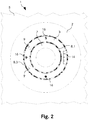
- Fig. 2 schematically shows a plan view of a fitting base 1 according to the invention, which comprises a housing 2 which can be installed in a sanitary device 5 and in which the rotating base 3 is rotatably mounted.
- the feed sleeve 7 is arranged in the rotary base 3, the sealing ring 8.1 being located between them.
- the sealing ring 8.3 is located between the housing 2 and the rotating base 3.
- the guide pins 9 can, for example, have a thread and be screwed into corresponding threaded bores in the rotary base 3.
- a corresponding slot can be milled in the rotary base 3 in order to arrange the transmission plate 14 therein.
- the fitting can be plugged onto the rotating base 3, the guide pins 9 engaging in corresponding recesses in the fitting as shown below and centering and guiding them on the rotating base 3 when plugged in.
- one or more magnets 16 can be arranged in the rotary base 3, which hold the armature on the rotary base 3 by means of a magnetic attraction.
- securing bolts or any other mechanical devices can be provided in order to attach the fitting to the rotating base 3.
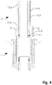
- Fig. 3 shows schematically a cross section of a fitting base 1 according to the invention and parts of a fitting 17.
- the fitting 17 has a fitting line 17.3 which is arranged in a fitting housing 17.6. If required, the valve line 17.3 and the valve housing 17.6 can also be formed in one piece.
- the fitting housing 17.6 has one or more guides 17.5 for receiving the one or more guide pins 9 of the fitting base 3. Furthermore, electrical transmission lines 17.4 are provided on the armature 17 in order to create an electrical connection between the transmission plate 14 and electronic components arranged on the armature 17 when the armature 17 is plugged onto the rotary base 3.
- valve line 17.3 At the end of the valve line 17.3 are as in Fig. 3 shown one or more sealing rings 17.1, 17.2 attached.
- the fitting line 17.3 and the sealing rings 17.1, 17.2 are dimensioned such that they can be inserted into the rotating base bushing 3.0 in order to form a fluid-tight connection between the fitting line 17.3 and the inflow sleeve 7.
- the fitting 17 can relate to a faucet for a wash basin, a faucet for a bathtub, a shower head, a faucet for a kitchen sink or any other fitting and has a water outlet and electronic components such as display means as well Setting means for displaying and setting one or more parameters.
- the water outlet is set up in order to deliver a water flow, which is conducted via the inflow sleeve 7 and the fitting line 17.3, in the desired manner; the display means and the setting means can relate to conventional devices.
- the display means can be designed as an electronic display and the setting means as electrical buttons or switches.
- a fitting 17 attached to the rotary base 3 there is an electrical connection between the components arranged in the fitting 17 to a control or regulating unit, specifically via the electrical transmission lines 17.4, the transmission plate 14, the slip rings 13.1, 13.2, 13.3, the contact pins 12.1, 12.2, 12.3 and the connecting lines 15.
- the control or regulating unit is set up to set regulating elements such as a mixing valve or a volume valve in order to set a required water temperature, water quantity, water speed, water pressure or any other parameter.
- Fig. 4 shows schematically a first phase of the process when fitting the fitting 17 onto the rotary base 3.
- the one or more guide pins 9 are partially inserted into the guides 17.5 and a first sealing ring 17.1 is located directly at the corresponding end of the rotary base leadthrough 3.0.
- a fluid-tight connection between the fitting line 17.3 and the rotating base leadthrough 3.0 begins to form, which is reinforced when the fitting 17 is plugged onto the rotating base 3 as a result of the second sealing ring 17.2.
- this first phase of fitting the fitting 17 onto the rotary base 3 there is no contact between the electrical transmission lines 17.4 and the transmission plate 14.
- no signals can reach the control or regulating unit and water cannot accidentally flow out of the inflow sleeve 7 before the tightness between the fitting 17 and the rotary base 3 is ensured.
- Fig. 5 schematically shows a fitting 17 which is completely plugged onto the rotating base 3.
- the valve 17 is for example from in Fig. 2 Magnet 16 shown held and / or a bolt 17.7 can be provided for mechanical securing, which forms a mechanical coupling between the rotating base collar 3.1 and the valve body 17.
- the fitting 17 can comprise electronic identification means, on the basis of which a control or regulating unit can determine parameters of the fitting 17, on the basis of which, for example, a permissible maximum water temperature, water speed, water quantity, a permissible maximum water pressure or some other maximum value is defined. For example, ensure that a user is not scalded or that a maximum amount of water for a sink or bathtub is automatically maintained.
- an operating or display device can be provided, which can be operated and read particularly easily by wheelchair-dependent people.
- the rotating base 3 and the slip rings 13.1, 13.2, 13.3 ensure the electrical connection for signal and energy transmission between the fitting 17 and other electrical units, as well as high flexibility with regard to the angle of rotation.
- wireless technologies e.g. WiFi, IrDA, Bluetooth, etc.
- magnetic induction can also be used for wireless energy transmission.
- the fitting 17 can be easily changed without special expertise and thus sanitary facilities can be quickly and easily adapted to changing needs. In addition to technically different fittings, different fittings can also be conveniently used.
- a valve can be changed within seconds. It is not necessary to e.g. to put under a washstand. A valve is replaced by simply unplugging an old valve and inserting a new valve. No tools are required for this.
- the dimensions of the fitting and the fitting base are coordinated so that incorrect assembly is not possible.
- the valve can For safety reasons, only transmit electrical signals to a control or regulating unit when the water line is tight.
- the same fitting base can be used for both a standing and a wall fitting. Depending on the application, different mounting accessories may be supplied with the valve base.
- the fitting can also be connected to a flexible hose which is passed through the rotating base. This allows the user to pull a shower out of the faucet into a specific area to do work that cannot be done in close proximity to the faucet base.
- FIG. 6 schematically shows a further embodiment of a fitting 17b, which is completely attached to a rotating base 3b of a fitting base 1b and is thereby secured with a snap spring 18.
- the snap spring 18 is firmly connected to the armature 17b and engages in an outer holding contour 2b.2 of the housing 2b. This results in a positive connection between the fitting 17b and the fitting base 1b, in particular between the fitting 17b and the housing 2b or the housing collar 2b.1.
- an acoustic signal sounds in the form of a click, which signals to a user that the fitting 17b is correctly attached to the fitting base 1b.
- a defined force must be applied by the user in order to overcome a pressure point. Overcoming this pressure point also has a signal effect.
Landscapes
- Health & Medical Sciences (AREA)
- Life Sciences & Earth Sciences (AREA)
- Engineering & Computer Science (AREA)
- Hydrology & Water Resources (AREA)
- Public Health (AREA)
- Water Supply & Treatment (AREA)
- Multiple-Way Valves (AREA)
- Domestic Plumbing Installations (AREA)
Claims (8)
- Socle de robinetterie sans soupape (1) pour des équipements sanitaires, comprenanta) un guide de fluide,b) une interface de signal électrique et/ou une interface d'énergie électrique pour la transmission de signaux de commande électriques et/ou d'énergie électrique entre le socle de robinetterie (1) et une robinetterie emboîtable (17),c) un corps (2), etcaractérisé en ce que le socle de robinetterie sans soupape (1) comprend en outre:
d) un socle tournant (3) monté de façon rotative dans le corps (2) pour l'emboîtement d'une robinetterie emboîtable (17), dans lequel il est adapté pour empêcher une rotation entre le socle tournant (3) et la robinetterie emboîtée(17). - Socle de robinetterie selon la revendication 1, caractérisé en ce que le socle tournant (3) présente une ou plusieurs bague(s) collectrice(s) (13.1, 13.2, 13.3) et le corps (2) du socle de robinetterie (1) présente une ou plusieurs tige(s) de contact (12.1, 12.2, 12.3) pour la mise en contact des bagues collectrices (13.1, 13.2, 13.3), pour former une ou plusieurs liaison(s) électrique(s) en vue de la transmission de signaux électriques et/ou d'énergie électrique entre le socle de robinetterie (1) et une robinetterie emboîtée (17).
- Socle de robinetterie selon la revendication 1 ou 2, caractérisé en ce qu'il est prévu des interfaces sans fil pour la transmission de signaux de commande électriques et/ou pour une transmission d'énergie électrique entre le socle de robinetterie (1) et une robinetterie emboîtée (17).
- Socle de robinetterie selon l'une quelconque des revendications 1 à 3, caractérisé en ce qu'une douille d'alimentation (7) est installée dans une traversée de socle tournant (3.0) du socle tournant (3), dans lequel une communication fluidique pour une alimentation de fluide est établie de la douille d'alimentation (7) à la traversée de socle tournant (3.0), et dans lequel des moyens d'étanchéité sont disposés entre la douille d'alimentation (7) et la traversée de socle tournant (3.0).
- Socle de robinetterie selon l'une quelconque des revendications 1 à 4, caractérisé en ce qu'il est prévu sur le socle tournant (3) une ou plusieurs tige(s) de guidage (9) pour guider la robinetterie emboîtable (17) et empêcher une rotation de la robinetterie emboîtable (17) par rapport au socle tournant (3) et/ou une plaque de transmission (14) pour l'établissement d'une ou de plusieurs liaison(s) électrique(s) entre le socle tournant (3) et la robinetterie emboîtable (17).
- Socle de robinetterie selon l'une quelconque des revendications 1 à 5, caractérisé en ce qu'il est prévu au moins une butée pour la limitation de l'angle de rotation du socle tournant (3).
- Socle de robinetterie selon l'une quelconque des revendications 1 à 6, caractérisé en ce que le socle tournant (3) est conçu pour coopérer mécaniquement avec une robinetterie emboîtable (17) et pour maintenir celle-ci sur le socle tournant (3) ou pour l'y fixer.
- Socle de robinetterie selon l'une quelconque des revendications précédentes, caractérisé en ce que le socle de robinetterie (1, 1b) comprend un contour de maintien (2b.2) pour le logement au moins partiel d'une fixation de sécurité (18) de la robinetterie (17, 17b).
Applications Claiming Priority (3)
| Application Number | Priority Date | Filing Date | Title |
|---|---|---|---|
| CH002044/2010A CH704188B1 (de) | 2010-12-06 | 2010-12-06 | Ventilloser Armatursockel und ventillose aufsteckbare Armatur. |
| PCT/CH2011/000292 WO2012075593A1 (fr) | 2010-12-06 | 2011-12-05 | Socle de robinetterie et robinetterie emboîtable |
| EP11794398.5A EP2649247B8 (fr) | 2010-12-06 | 2011-12-05 | Socle de robinetterie pour robinetterie emboîtable |
Related Parent Applications (2)
| Application Number | Title | Priority Date | Filing Date |
|---|---|---|---|
| EP11794398.5A Division EP2649247B8 (fr) | 2010-12-06 | 2011-12-05 | Socle de robinetterie pour robinetterie emboîtable |
| EP11794398.5A Division-Into EP2649247B8 (fr) | 2010-12-06 | 2011-12-05 | Socle de robinetterie pour robinetterie emboîtable |
Publications (3)
| Publication Number | Publication Date |
|---|---|
| EP3284871A1 EP3284871A1 (fr) | 2018-02-21 |
| EP3284871B1 true EP3284871B1 (fr) | 2020-07-15 |
| EP3284871B8 EP3284871B8 (fr) | 2020-08-26 |
Family
ID=44147652
Family Applications (2)
| Application Number | Title | Priority Date | Filing Date |
|---|---|---|---|
| EP11794398.5A Not-in-force EP2649247B8 (fr) | 2010-12-06 | 2011-12-05 | Socle de robinetterie pour robinetterie emboîtable |
| EP17170480.2A Active EP3284871B8 (fr) | 2010-12-06 | 2011-12-05 | Socle de robinetterie |
Family Applications Before (1)
| Application Number | Title | Priority Date | Filing Date |
|---|---|---|---|
| EP11794398.5A Not-in-force EP2649247B8 (fr) | 2010-12-06 | 2011-12-05 | Socle de robinetterie pour robinetterie emboîtable |
Country Status (3)
| Country | Link |
|---|---|
| EP (2) | EP2649247B8 (fr) |
| CH (1) | CH704188B1 (fr) |
| WO (1) | WO2012075593A1 (fr) |
Families Citing this family (9)
| Publication number | Priority date | Publication date | Assignee | Title |
|---|---|---|---|---|
| CH704188B1 (de) * | 2010-12-06 | 2023-06-30 | Eliane Zoccolillo Luethi | Ventilloser Armatursockel und ventillose aufsteckbare Armatur. |
| DE102013115006A1 (de) * | 2013-12-31 | 2015-07-02 | Frank Gissmann | Wasserauslaufanordnung, Sanitäreinrichtung mit einer Wasserauslaufanordnung und Schnellkupplung |
| ITUB20159371A1 (it) * | 2015-12-23 | 2017-06-23 | Giacomini Investimenti S R L | Dispositivo di sostegno per bocca di erogazione acqua |
| US11408543B2 (en) | 2018-02-28 | 2022-08-09 | Kohler Co. | Articulating faucet |
| US10890277B2 (en) * | 2018-02-28 | 2021-01-12 | Kohler Co. | Articulating faucet with progressive magnetic joint |
| US11125365B2 (en) | 2018-02-28 | 2021-09-21 | Kohler Co. | Magnetic joint |
| US11214946B2 (en) | 2018-06-04 | 2022-01-04 | Kohler Co. | Articulating faucet |
| US11242675B2 (en) | 2018-06-04 | 2022-02-08 | Kohler Co. | Articulating faucet |
| DE102019105517A1 (de) * | 2019-03-05 | 2020-09-10 | Grohe Ag | Verfahren zum Betrieb einer Sanitärarmatur und Vorrichtung zur Durchführung des Verfahrens |
Family Cites Families (11)
| Publication number | Priority date | Publication date | Assignee | Title |
|---|---|---|---|---|
| NO155261C (no) * | 1984-02-22 | 1987-03-04 | Lyng Ind As | Sanitaersystem for levering av varmt og kaldt vann. |
| GB2172413B (en) * | 1985-03-12 | 1988-11-02 | Caradon Mira Ltd | Water supply installation for ablutionary purposes |
| JPH11336143A (ja) * | 1998-05-22 | 1999-12-07 | Uro Denshi Kogyo Kk | 自動水栓 |
| DE20209799U1 (de) | 2002-06-24 | 2003-11-13 | Bolderheij Fok Cornelis | Multifunktionsarmatur |
| EP1870526B1 (fr) * | 2006-06-21 | 2016-04-06 | Franke Water Systems AG | Robinet sanitaire |
| CH698596B1 (de) * | 2006-12-06 | 2009-09-15 | Giuseppe Zoccolillo | Sanitäre Hausinstallation. |
| DE102007010964A1 (de) * | 2007-03-05 | 2008-09-11 | Aquis Sanitär AG | Sanitäreinrichtung |
| DE202007004831U1 (de) | 2007-04-02 | 2008-08-07 | Reich Kg, Regel- Und Sicherheitstechnik | Wasserarmatur |
| DE202007004832U1 (de) | 2007-04-02 | 2008-08-07 | Reich Kg, Regel- Und Sicherheitstechnik | Befestigungsvorrichtung für eine Wasserarmatur |
| EP2169123B1 (fr) * | 2008-09-24 | 2014-12-31 | Geberit International AG | Robinetterie d'eau commandée sans contact |
| CH704188B1 (de) * | 2010-12-06 | 2023-06-30 | Eliane Zoccolillo Luethi | Ventilloser Armatursockel und ventillose aufsteckbare Armatur. |
-
2010
- 2010-12-06 CH CH002044/2010A patent/CH704188B1/de unknown
-
2011
- 2011-12-05 WO PCT/CH2011/000292 patent/WO2012075593A1/fr not_active Ceased
- 2011-12-05 EP EP11794398.5A patent/EP2649247B8/fr not_active Not-in-force
- 2011-12-05 EP EP17170480.2A patent/EP3284871B8/fr active Active
Non-Patent Citations (1)
| Title |
|---|
| None * |
Also Published As
| Publication number | Publication date |
|---|---|
| WO2012075593A1 (fr) | 2012-06-14 |
| EP3284871A1 (fr) | 2018-02-21 |
| EP2649247B8 (fr) | 2017-08-02 |
| CH704188B1 (de) | 2023-06-30 |
| EP2649247A1 (fr) | 2013-10-16 |
| EP2649247B1 (fr) | 2017-05-17 |
| EP3284871B8 (fr) | 2020-08-26 |
| CH704188A1 (de) | 2012-06-15 |
Similar Documents
| Publication | Publication Date | Title |
|---|---|---|
| EP3284871B1 (fr) | Socle de robinetterie | |
| CN107426976B (zh) | 灌溉连接器以及相关的设备、套件和系统 | |
| DE4420330A1 (de) | Wasserarmatur mit elektrischer Steuerung | |
| DE202014006320U1 (de) | Anschlussvorrichtung und sanitäre Anlage | |
| EP3052710A1 (fr) | Plaque de montage pour corps de wc | |
| DE102013101120A1 (de) | Kabelfixierung | |
| EP2907929B1 (fr) | Système d'évacuation d'eau et dispositif sanitaire doté d'un système d'évacuation d'eau | |
| EP0757134A1 (fr) | Dispositif d'écoulement | |
| DE202007004832U1 (de) | Befestigungsvorrichtung für eine Wasserarmatur | |
| DE102007015424A1 (de) | Berührungslos steuerbare Waschtischarmatur | |
| EP0937828A2 (fr) | Robinetterie sanitaire avec raccord de tuyauterie | |
| DE1904285B2 (de) | WandanschluBstück für Schlauchbrausen | |
| EP1616998A2 (fr) | Armature sanitaire mural | |
| EP3947836A1 (fr) | Robinetterie sanitaire comprenant une unité d'enfichage | |
| DE202017102744U1 (de) | Vorrichtung zum Anschluss eines Duschschlauchs an eine Armatur | |
| CN207161850U (zh) | 一种防盗安全把手及防盗水水龙头 | |
| EP1978166A2 (fr) | Robinetterie d'eau | |
| DE102004037051A1 (de) | Mischbatterie mit Standanschluss | |
| DE10247066B4 (de) | Sanitärarmatur mit Anschlussstück | |
| WO2019174903A1 (fr) | Robinet sanitaire | |
| DE10230851B4 (de) | Sanitärarmatur | |
| DE2324023C3 (de) | UnterputzanschluBstück für Sanitärarmaturen | |
| DE102023115254A1 (de) | Sanitärarmatur und Sanitärarmaturensystem | |
| DE3346081A1 (de) | Mischbatterie mit standanschluss | |
| EP4056772A1 (fr) | Robinetterie dotée d'un capteur de débit |
Legal Events
| Date | Code | Title | Description |
|---|---|---|---|
| PUAI | Public reference made under article 153(3) epc to a published international application that has entered the european phase |
Free format text: ORIGINAL CODE: 0009012 |
|
| STAA | Information on the status of an ep patent application or granted ep patent |
Free format text: STATUS: THE APPLICATION HAS BEEN PUBLISHED |
|
| AC | Divisional application: reference to earlier application |
Ref document number: 2649247 Country of ref document: EP Kind code of ref document: P |
|
| AK | Designated contracting states |
Kind code of ref document: A1 Designated state(s): AL AT BE BG CH CY CZ DE DK EE ES FI FR GB GR HR HU IE IS IT LI LT LU LV MC MK MT NL NO PL PT RO RS SE SI SK SM TR |
|
| STAA | Information on the status of an ep patent application or granted ep patent |
Free format text: STATUS: REQUEST FOR EXAMINATION WAS MADE |
|
| 17P | Request for examination filed |
Effective date: 20180817 |
|
| RBV | Designated contracting states (corrected) |
Designated state(s): AL AT BE BG CH CY CZ DE DK EE ES FI FR GB GR HR HU IE IS IT LI LT LU LV MC MK MT NL NO PL PT RO RS SE SI SK SM TR |
|
| STAA | Information on the status of an ep patent application or granted ep patent |
Free format text: STATUS: EXAMINATION IS IN PROGRESS |
|
| 17Q | First examination report despatched |
Effective date: 20190909 |
|
| REG | Reference to a national code |
Ref country code: DE Ref legal event code: R079 Ref document number: 502011016805 Country of ref document: DE Free format text: PREVIOUS MAIN CLASS: E03C0001050000 Ipc: E03C0001040000 |
|
| RIC1 | Information provided on ipc code assigned before grant |
Ipc: E03C 1/04 20060101AFI20200108BHEP |
|
| GRAP | Despatch of communication of intention to grant a patent |
Free format text: ORIGINAL CODE: EPIDOSNIGR1 |
|
| STAA | Information on the status of an ep patent application or granted ep patent |
Free format text: STATUS: GRANT OF PATENT IS INTENDED |
|
| INTG | Intention to grant announced |
Effective date: 20200217 |
|
| GRAS | Grant fee paid |
Free format text: ORIGINAL CODE: EPIDOSNIGR3 |
|
| GRAA | (expected) grant |
Free format text: ORIGINAL CODE: 0009210 |
|
| STAA | Information on the status of an ep patent application or granted ep patent |
Free format text: STATUS: THE PATENT HAS BEEN GRANTED |
|
| AC | Divisional application: reference to earlier application |
Ref document number: 2649247 Country of ref document: EP Kind code of ref document: P |
|
| AK | Designated contracting states |
Kind code of ref document: B1 Designated state(s): AL AT BE BG CH CY CZ DE DK EE ES FI FR GB GR HR HU IE IS IT LI LT LU LV MC MK MT NL NO PL PT RO RS SE SI SK SM TR |
|
| RAP1 | Party data changed (applicant data changed or rights of an application transferred) |
Owner name: LOCCOZ SYSTEM AG |
|
| REG | Reference to a national code |
Ref country code: GB Ref legal event code: FG4D Free format text: NOT ENGLISH Ref country code: CH Ref legal event code: EP |
|
| REG | Reference to a national code |
Ref country code: IE Ref legal event code: FG4D Free format text: LANGUAGE OF EP DOCUMENT: GERMAN |
|
| REG | Reference to a national code |
Ref country code: DE Ref legal event code: R096 Ref document number: 502011016805 Country of ref document: DE |
|
| REG | Reference to a national code |
Ref country code: AT Ref legal event code: REF Ref document number: 1291180 Country of ref document: AT Kind code of ref document: T Effective date: 20200815 |
|
| RBV | Designated contracting states (corrected) |
Designated state(s): AL AT BE BG CY CZ DE DK EE ES FI FR GB GR HR HU IE IS IT LT LU LV MC MK MT NL NO PL PT RO RS SE SI SK SM TR |
|
| REG | Reference to a national code |
Ref country code: LT Ref legal event code: MG4D |
|
| REG | Reference to a national code |
Ref country code: NL Ref legal event code: MP Effective date: 20200715 |
|
| PG25 | Lapsed in a contracting state [announced via postgrant information from national office to epo] |
Ref country code: LT Free format text: LAPSE BECAUSE OF FAILURE TO SUBMIT A TRANSLATION OF THE DESCRIPTION OR TO PAY THE FEE WITHIN THE PRESCRIBED TIME-LIMIT Effective date: 20200715 Ref country code: PT Free format text: LAPSE BECAUSE OF FAILURE TO SUBMIT A TRANSLATION OF THE DESCRIPTION OR TO PAY THE FEE WITHIN THE PRESCRIBED TIME-LIMIT Effective date: 20201116 Ref country code: ES Free format text: LAPSE BECAUSE OF FAILURE TO SUBMIT A TRANSLATION OF THE DESCRIPTION OR TO PAY THE FEE WITHIN THE PRESCRIBED TIME-LIMIT Effective date: 20200715 Ref country code: BG Free format text: LAPSE BECAUSE OF FAILURE TO SUBMIT A TRANSLATION OF THE DESCRIPTION OR TO PAY THE FEE WITHIN THE PRESCRIBED TIME-LIMIT Effective date: 20201015 Ref country code: HR Free format text: LAPSE BECAUSE OF FAILURE TO SUBMIT A TRANSLATION OF THE DESCRIPTION OR TO PAY THE FEE WITHIN THE PRESCRIBED TIME-LIMIT Effective date: 20200715 Ref country code: FI Free format text: LAPSE BECAUSE OF FAILURE TO SUBMIT A TRANSLATION OF THE DESCRIPTION OR TO PAY THE FEE WITHIN THE PRESCRIBED TIME-LIMIT Effective date: 20200715 Ref country code: SE Free format text: LAPSE BECAUSE OF FAILURE TO SUBMIT A TRANSLATION OF THE DESCRIPTION OR TO PAY THE FEE WITHIN THE PRESCRIBED TIME-LIMIT Effective date: 20200715 Ref country code: NO Free format text: LAPSE BECAUSE OF FAILURE TO SUBMIT A TRANSLATION OF THE DESCRIPTION OR TO PAY THE FEE WITHIN THE PRESCRIBED TIME-LIMIT Effective date: 20201015 Ref country code: GR Free format text: LAPSE BECAUSE OF FAILURE TO SUBMIT A TRANSLATION OF THE DESCRIPTION OR TO PAY THE FEE WITHIN THE PRESCRIBED TIME-LIMIT Effective date: 20201016 |
|
| PG25 | Lapsed in a contracting state [announced via postgrant information from national office to epo] |
Ref country code: IS Free format text: LAPSE BECAUSE OF FAILURE TO SUBMIT A TRANSLATION OF THE DESCRIPTION OR TO PAY THE FEE WITHIN THE PRESCRIBED TIME-LIMIT Effective date: 20201115 Ref country code: LV Free format text: LAPSE BECAUSE OF FAILURE TO SUBMIT A TRANSLATION OF THE DESCRIPTION OR TO PAY THE FEE WITHIN THE PRESCRIBED TIME-LIMIT Effective date: 20200715 Ref country code: PL Free format text: LAPSE BECAUSE OF FAILURE TO SUBMIT A TRANSLATION OF THE DESCRIPTION OR TO PAY THE FEE WITHIN THE PRESCRIBED TIME-LIMIT Effective date: 20200715 Ref country code: RS Free format text: LAPSE BECAUSE OF FAILURE TO SUBMIT A TRANSLATION OF THE DESCRIPTION OR TO PAY THE FEE WITHIN THE PRESCRIBED TIME-LIMIT Effective date: 20200715 |
|
| PG25 | Lapsed in a contracting state [announced via postgrant information from national office to epo] |
Ref country code: NL Free format text: LAPSE BECAUSE OF FAILURE TO SUBMIT A TRANSLATION OF THE DESCRIPTION OR TO PAY THE FEE WITHIN THE PRESCRIBED TIME-LIMIT Effective date: 20200715 |
|
| REG | Reference to a national code |
Ref country code: DE Ref legal event code: R097 Ref document number: 502011016805 Country of ref document: DE |
|
| PG25 | Lapsed in a contracting state [announced via postgrant information from national office to epo] |
Ref country code: RO Free format text: LAPSE BECAUSE OF FAILURE TO SUBMIT A TRANSLATION OF THE DESCRIPTION OR TO PAY THE FEE WITHIN THE PRESCRIBED TIME-LIMIT Effective date: 20200715 Ref country code: DK Free format text: LAPSE BECAUSE OF FAILURE TO SUBMIT A TRANSLATION OF THE DESCRIPTION OR TO PAY THE FEE WITHIN THE PRESCRIBED TIME-LIMIT Effective date: 20200715 Ref country code: CZ Free format text: LAPSE BECAUSE OF FAILURE TO SUBMIT A TRANSLATION OF THE DESCRIPTION OR TO PAY THE FEE WITHIN THE PRESCRIBED TIME-LIMIT Effective date: 20200715 Ref country code: SM Free format text: LAPSE BECAUSE OF FAILURE TO SUBMIT A TRANSLATION OF THE DESCRIPTION OR TO PAY THE FEE WITHIN THE PRESCRIBED TIME-LIMIT Effective date: 20200715 Ref country code: EE Free format text: LAPSE BECAUSE OF FAILURE TO SUBMIT A TRANSLATION OF THE DESCRIPTION OR TO PAY THE FEE WITHIN THE PRESCRIBED TIME-LIMIT Effective date: 20200715 Ref country code: IT Free format text: LAPSE BECAUSE OF FAILURE TO SUBMIT A TRANSLATION OF THE DESCRIPTION OR TO PAY THE FEE WITHIN THE PRESCRIBED TIME-LIMIT Effective date: 20200715 |
|
| PLBE | No opposition filed within time limit |
Free format text: ORIGINAL CODE: 0009261 |
|
| STAA | Information on the status of an ep patent application or granted ep patent |
Free format text: STATUS: NO OPPOSITION FILED WITHIN TIME LIMIT |
|
| PG25 | Lapsed in a contracting state [announced via postgrant information from national office to epo] |
Ref country code: AL Free format text: LAPSE BECAUSE OF FAILURE TO SUBMIT A TRANSLATION OF THE DESCRIPTION OR TO PAY THE FEE WITHIN THE PRESCRIBED TIME-LIMIT Effective date: 20200715 |
|
| 26N | No opposition filed |
Effective date: 20210416 |
|
| PG25 | Lapsed in a contracting state [announced via postgrant information from national office to epo] |
Ref country code: SK Free format text: LAPSE BECAUSE OF FAILURE TO SUBMIT A TRANSLATION OF THE DESCRIPTION OR TO PAY THE FEE WITHIN THE PRESCRIBED TIME-LIMIT Effective date: 20200715 |
|
| GBPC | Gb: european patent ceased through non-payment of renewal fee |
Effective date: 20201205 |
|
| PG25 | Lapsed in a contracting state [announced via postgrant information from national office to epo] |
Ref country code: MC Free format text: LAPSE BECAUSE OF FAILURE TO SUBMIT A TRANSLATION OF THE DESCRIPTION OR TO PAY THE FEE WITHIN THE PRESCRIBED TIME-LIMIT Effective date: 20200715 Ref country code: SI Free format text: LAPSE BECAUSE OF FAILURE TO SUBMIT A TRANSLATION OF THE DESCRIPTION OR TO PAY THE FEE WITHIN THE PRESCRIBED TIME-LIMIT Effective date: 20200715 |
|
| REG | Reference to a national code |
Ref country code: BE Ref legal event code: MM Effective date: 20201231 |
|
| PG25 | Lapsed in a contracting state [announced via postgrant information from national office to epo] |
Ref country code: LU Free format text: LAPSE BECAUSE OF NON-PAYMENT OF DUE FEES Effective date: 20201205 Ref country code: IE Free format text: LAPSE BECAUSE OF NON-PAYMENT OF DUE FEES Effective date: 20201205 Ref country code: FR Free format text: LAPSE BECAUSE OF NON-PAYMENT OF DUE FEES Effective date: 20201231 |
|
| PG25 | Lapsed in a contracting state [announced via postgrant information from national office to epo] |
Ref country code: GB Free format text: LAPSE BECAUSE OF NON-PAYMENT OF DUE FEES Effective date: 20201205 |
|
| PG25 | Lapsed in a contracting state [announced via postgrant information from national office to epo] |
Ref country code: IS Free format text: LAPSE BECAUSE OF FAILURE TO SUBMIT A TRANSLATION OF THE DESCRIPTION OR TO PAY THE FEE WITHIN THE PRESCRIBED TIME-LIMIT Effective date: 20201115 Ref country code: TR Free format text: LAPSE BECAUSE OF FAILURE TO SUBMIT A TRANSLATION OF THE DESCRIPTION OR TO PAY THE FEE WITHIN THE PRESCRIBED TIME-LIMIT Effective date: 20200715 Ref country code: MT Free format text: LAPSE BECAUSE OF FAILURE TO SUBMIT A TRANSLATION OF THE DESCRIPTION OR TO PAY THE FEE WITHIN THE PRESCRIBED TIME-LIMIT Effective date: 20200715 Ref country code: CY Free format text: LAPSE BECAUSE OF FAILURE TO SUBMIT A TRANSLATION OF THE DESCRIPTION OR TO PAY THE FEE WITHIN THE PRESCRIBED TIME-LIMIT Effective date: 20200715 |
|
| PG25 | Lapsed in a contracting state [announced via postgrant information from national office to epo] |
Ref country code: MK Free format text: LAPSE BECAUSE OF FAILURE TO SUBMIT A TRANSLATION OF THE DESCRIPTION OR TO PAY THE FEE WITHIN THE PRESCRIBED TIME-LIMIT Effective date: 20200715 |
|
| PG25 | Lapsed in a contracting state [announced via postgrant information from national office to epo] |
Ref country code: BE Free format text: LAPSE BECAUSE OF NON-PAYMENT OF DUE FEES Effective date: 20201231 |
|
| PGFP | Annual fee paid to national office [announced via postgrant information from national office to epo] |
Ref country code: DE Payment date: 20251211 Year of fee payment: 15 |
|
| PGFP | Annual fee paid to national office [announced via postgrant information from national office to epo] |
Ref country code: AT Payment date: 20251222 Year of fee payment: 15 |