EP3286443B1 - Fahrmaschine für ein gewässer mit einem lager - Google Patents
Fahrmaschine für ein gewässer mit einem lager Download PDFInfo
- Publication number
- EP3286443B1 EP3286443B1 EP16726107.2A EP16726107A EP3286443B1 EP 3286443 B1 EP3286443 B1 EP 3286443B1 EP 16726107 A EP16726107 A EP 16726107A EP 3286443 B1 EP3286443 B1 EP 3286443B1
- Authority
- EP
- European Patent Office
- Prior art keywords
- bearing
- water
- shaft
- machine
- magnetic bearing
- Prior art date
- Legal status (The legal status is an assumption and is not a legal conclusion. Google has not performed a legal analysis and makes no representation as to the accuracy of the status listed.)
- Active
Links
Images

Classifications
-
- F—MECHANICAL ENGINEERING; LIGHTING; HEATING; WEAPONS; BLASTING
- F16—ENGINEERING ELEMENTS AND UNITS; GENERAL MEASURES FOR PRODUCING AND MAINTAINING EFFECTIVE FUNCTIONING OF MACHINES OR INSTALLATIONS; THERMAL INSULATION IN GENERAL
- F16C—SHAFTS; FLEXIBLE SHAFTS; ELEMENTS OR CRANKSHAFT MECHANISMS; ROTARY BODIES OTHER THAN GEARING ELEMENTS; BEARINGS
- F16C32/00—Bearings not otherwise provided for
- F16C32/04—Bearings not otherwise provided for using magnetic or electric supporting means
- F16C32/0406—Magnetic bearings
- F16C32/044—Active magnetic bearings
- F16C32/0474—Active magnetic bearings for rotary movement
-
- B—PERFORMING OPERATIONS; TRANSPORTING
- B63—SHIPS OR OTHER WATERBORNE VESSELS; RELATED EQUIPMENT
- B63H—MARINE PROPULSION OR STEERING
- B63H5/00—Arrangements on vessels of propulsion elements directly acting on water
- B63H5/07—Arrangements on vessels of propulsion elements directly acting on water of propellers
- B63H5/125—Arrangements on vessels of propulsion elements directly acting on water of propellers movably mounted with respect to hull, e.g. adjustable in direction, e.g. podded azimuthing thrusters
- B63H2005/1254—Podded azimuthing thrusters, i.e. podded thruster units arranged inboard for rotation about vertical axis
- B63H2005/1258—Podded azimuthing thrusters, i.e. podded thruster units arranged inboard for rotation about vertical axis with electric power transmission to propellers, i.e. with integrated electric propeller motors
-
- F—MECHANICAL ENGINEERING; LIGHTING; HEATING; WEAPONS; BLASTING
- F16—ENGINEERING ELEMENTS AND UNITS; GENERAL MEASURES FOR PRODUCING AND MAINTAINING EFFECTIVE FUNCTIONING OF MACHINES OR INSTALLATIONS; THERMAL INSULATION IN GENERAL
- F16C—SHAFTS; FLEXIBLE SHAFTS; ELEMENTS OR CRANKSHAFT MECHANISMS; ROTARY BODIES OTHER THAN GEARING ELEMENTS; BEARINGS
- F16C2326/00—Articles relating to transporting
- F16C2326/30—Ships, e.g. propelling shafts and bearings therefor
-
- F—MECHANICAL ENGINEERING; LIGHTING; HEATING; WEAPONS; BLASTING
- F16—ENGINEERING ELEMENTS AND UNITS; GENERAL MEASURES FOR PRODUCING AND MAINTAINING EFFECTIVE FUNCTIONING OF MACHINES OR INSTALLATIONS; THERMAL INSULATION IN GENERAL
- F16C—SHAFTS; FLEXIBLE SHAFTS; ELEMENTS OR CRANKSHAFT MECHANISMS; ROTARY BODIES OTHER THAN GEARING ELEMENTS; BEARINGS
- F16C32/00—Bearings not otherwise provided for
- F16C32/04—Bearings not otherwise provided for using magnetic or electric supporting means
- F16C32/0406—Magnetic bearings
- F16C32/044—Active magnetic bearings
- F16C32/0474—Active magnetic bearings for rotary movement
- F16C32/0476—Active magnetic bearings for rotary movement with active support of one degree of freedom, e.g. axial magnetic bearings
-
- F—MECHANICAL ENGINEERING; LIGHTING; HEATING; WEAPONS; BLASTING
- F16—ENGINEERING ELEMENTS AND UNITS; GENERAL MEASURES FOR PRODUCING AND MAINTAINING EFFECTIVE FUNCTIONING OF MACHINES OR INSTALLATIONS; THERMAL INSULATION IN GENERAL
- F16C—SHAFTS; FLEXIBLE SHAFTS; ELEMENTS OR CRANKSHAFT MECHANISMS; ROTARY BODIES OTHER THAN GEARING ELEMENTS; BEARINGS
- F16C32/00—Bearings not otherwise provided for
- F16C32/04—Bearings not otherwise provided for using magnetic or electric supporting means
- F16C32/0406—Magnetic bearings
- F16C32/044—Active magnetic bearings
- F16C32/0474—Active magnetic bearings for rotary movement
- F16C32/048—Active magnetic bearings for rotary movement with active support of two degrees of freedom, e.g. radial magnetic bearings
-
- F—MECHANICAL ENGINEERING; LIGHTING; HEATING; WEAPONS; BLASTING
- F16—ENGINEERING ELEMENTS AND UNITS; GENERAL MEASURES FOR PRODUCING AND MAINTAINING EFFECTIVE FUNCTIONING OF MACHINES OR INSTALLATIONS; THERMAL INSULATION IN GENERAL
- F16C—SHAFTS; FLEXIBLE SHAFTS; ELEMENTS OR CRANKSHAFT MECHANISMS; ROTARY BODIES OTHER THAN GEARING ELEMENTS; BEARINGS
- F16C32/00—Bearings not otherwise provided for
- F16C32/04—Bearings not otherwise provided for using magnetic or electric supporting means
- F16C32/0406—Magnetic bearings
- F16C32/044—Active magnetic bearings
- F16C32/0474—Active magnetic bearings for rotary movement
- F16C32/0485—Active magnetic bearings for rotary movement with active support of three degrees of freedom
Definitions
- the invention relates to a driving machine for a body of water with a rotatable shaft, which is in particular a drive shaft for at least one propeller.
- Examples of a driving machine for a body of water are container ships, passenger ships, pod drives, rudder propellers, freighters, submarines, etc.
- Waters are, for example, seas, rivers, lakes, etc.
- Such driving machines for a body of water, ie in particular submarines, ships and boats are drivable by means of a propeller, the propeller being mechanically coupled to a drive shaft.
- a float such as a ship or a submarine, as well as a part of it can be understood. This is for example a drive nacelle.
- the EP 1 972 545 A1 shows, for example, a driving machine for a body of water that serves as a pod drive for a ship.
- the driving machine for a body of water has in particular an underwater housing, which is arranged on the hull of the ship, a propeller, which is arranged outside of the housing, and a propeller shaft (ie a drive shaft), on which the propeller sits on.
- the propeller shaft is mounted in the housing.
- the housing has one or a plurality of passage openings, via which the propeller shaft is guided out of the housing.
- a transmission in the form of a planetary gear is arranged, which is coupled to the propeller shaft and having a transmission housing.
- the propeller can also be driven directly, ie without gearbox.
- a shaft seal seals the passage opening against entry of liquid into the housing.
- the gear is in particular spaced from the shaft seal.
- the drive of the propeller shaft or of the propeller via the optionally used transmission is effected by a drive motor device, which contains, for example, an electric motor.
- This electric motor is arranged in a pod drive inside the housing. If the electric motor is arranged outside the housing in the ship's hull, then it is a rudder propeller.
- the drive of the propeller shaft or the propeller via a vertical shaft which is guided by the hull into the housing, and arranged between the gearbox and the vertical shaft crown gear bevel gear. Designs without gears are also possible.
- the Propellerwellenlagerung so the storage of the drive shaft for a driving machine for a body of water such as a watercraft, for example, for an azimutierenden electric drive, by different rolling bearings, plain bearings and / or WälzGleitlageran effetguinen and executions ausgestaltbar.
- the WO 00/37308 A discloses a driving machine for a body of water having a propeller and a shaft which is coupled to the propeller, wherein a bearing for supporting the shaft is a magnetic bearing, wherein the bearing action is amplifiable, wherein provided for supporting the shaft, a first bearing and a second bearing is, wherein the first bearing absorbs axial forces, wherein the second bearing receives radial forces.
- An object of the invention is to improve the bearing of the drive shaft. Improved storage can be used, for example, to improve the efficiency of the drive system and / or the reliability and / or the number of operating hours and / or the maintenance intervals.
- a solution of the problem results in a driving machine for a body of water according to claim 1.
- a driving machine for a body of water such as a container ship, a passenger ship, a pod drive, a freighter, a submarine, a compressor, has a propeller and a shaft.
- the driving machine may have one or a plurality of propellers.
- the driving machine may also have one or a plurality of shafts.
- the shaft is in particular a drive shaft, which directly without a transmission or indirectly by means of a transmission, an electrical machine, such as an electric motor or an electric generator, coupled with the propeller.
- the coupling is particularly mechanical, wherein the shaft is mounted in particular within a housing, such as a nacelle mounted on the hull (pod drive).
- the bearing for supporting the shaft is designed as a magnetic bearing.
- An advantage of the magnetic design of a bearing may be that it is wear-free executable with respect to mechanical components. A freedom from wear, for example, is not given for rolling bearings.
- a magnetic bearing may be active or a plurality of magnetic bearings.
- a magnetic bearing depending on the load with different currents and / or voltages.
- the low-friction operation has a loss-reducing effect.
- the magnetic bearing can be formed in such a way that no lubricating media are required for storage, as a result of which no lubricating media can escape into the environment. If necessary, it is advisable to use a lubricating medium such as a grease or an oil for a backup bearing.
- the magnetic bearing it is an active magnetic bearing.
- the active magnetic bearing it is possible to control the energization of the windings of the magnetic bearing.
- a decoupling of the vibrations of the shaft, in particular the drive shaft, ie in particular the propeller shaft, can be achieved.
- the propeller is mechanically rigidly coupled.
- this has at least one magnetic bearing and at least one mechanical bearing for supporting the shaft.
- the mechanical bearing is, for example, a ball bearing, a roller bearing, a needle bearing, etc.
- the driving machine for a body of water, it has a first bearing and a second bearing for supporting the shaft.
- first bearing for example, high loads and / or different loads are taken into account.
- the first bearing is designed to absorb axial forces.
- the first bearing is thus able to absorb larger axial forces than radial forces.
- the orientation of the forces in the axial direction or in the radial direction depends on the shaft.
- the second bearing is designed to absorb radial forces.
- the second bearing is thus able to absorb larger radial forces than axial forces.
- the orientation is directed the forces in the axial direction or in the radial direction of the shaft.
- a propeller shaft bearing of azimutierenden electric drives for watercraft can be optimized by a magnetic bearing. This is also possible, for example, through the use of superconductors.
- a superconducting magnetic bearing can absorb particularly high forces and also enables a compact construction.
- Azimuthing electric drives are in driving machines for a body of water with a drive means for a floating and / or diving device, such. a ship or an offshore platform can be used, wherein the driving machine for a body of water, in particular horizontally and / or vertically or in particular rotatable about its spatially free axis, is attached to a hull of the floating or diving device.
- both the radial bearing and the axial bearing of the propeller shaft and / or the motor can be designed as a magnetic bearing. But there are also combinations of bearings (radial bearings or thrust bearings) with magnetic bearings (thrust bearings or radial bearings) possible.
- a transmission has at least one magnetic bearing.
- the propeller is coupled to the drive (eg an electric machine).
- the transmission can be formed in such a way that, during operation of the driving machine for a body of water, the speed of the electric machine is greater than the speed of the propeller shaft (eg 4 to 5 times the propeller speed).
- a high-speed machine can then be used, which has smaller dimensions than a machine running at the speed of the propeller. This is especially true when using the driving machine for a body of water as a propulsion device for a floating or diving device such as a submarine.
- the electric machine can be designed as an electric motor that drives the propeller.
- electric motors a wide variety of electric motors such as asynchronous or synchronous motors are possible, which can be energized by permanent magnets or a winding system, which can also be implemented in HTS (high-temperature superconductor) technology.
- the electric machine can also be designed as a generator, which is driven by the propeller.
- the shaft is coupled to an electric machine.
- Electric machines are simpler and more precisely controllable compared to internal combustion engines such as a diesel engine.
- the transmission is coupled to the electric machine and a propeller.
- the magnetic bearing can absorb forces that originate from the transmission and / or from the electric machine.
- the magnetic bearing and / or a power converter of the magnetic bearing is cooled.
- the converter or the coils of the magnetic bearing can be energized.
- To increase the efficiency can be provided individually or in combination cooling of power converters and magnetic bearings.
- the cooling of the magnetic bearing and / or a power converter of the magnetic bearing is thermally with the cooling of the electric machine and / or with the cooling of the power converter for the coupled electrical machine.
- common cooling circuits the space occupied by the cooling space can be reduced.
- the magnetic bearing has a superconductor. If the electric machine also has a superconductor, efficient supercooling of the electrical machine and magnetic bearing can be achieved by means of joint cooling.
- the electric machine and the magnetic bearing is located in a housing, wherein the housing relates to a nacelle drive.
- the nacelle drive can be designed as an azimuthal electric drive unit.
- the housing in which the electric machine and the magnetic bearing are located is a pressure body, as is required in submarines.
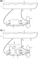
- FIG. 1 shows in simplified and schematic representation of a driving machine for a body of water 1 with a hull 42 and indicated waterline 11.
- the driving machine for a body of water 1 has a nacelle drive.
- a housing 2 of the nacelle drive is an electric machine 5, by means of which a propeller 3 can be driven via a shaft 4.
- the shaft 4 is supported by a drive-side bearing 7 and an operating-side bearing 8 within the housing 2.
- the drive-side bearing 7 and or the service-side bearing 8 are designed as a magnetic bearing. The use of magnetic bearings can reduce friction losses.
- FIG. 2 shows a driving machine for a body of water 1 similar to the FIG. 1 ,
- the driving machine for a body of water 1 has a gear 6 between the electric machine 5 and the propeller 3.
- the drive-side magnetic bearing 7 is fed via a power converter 38.
- the operator-side magnetic bearing 8 is powered by a power converter 37.
- the electric machine 5 is powered by a power converter 39.
- a cooling device 23 is provided for cooling electrical equipment such as power converters.
- the cooling device 23 can be the bearings 7 and 8, the power converters 37, 38 and 39 and the electric machine 5 to cool, which is indicated by dashed lines.
- the transmission can also be cooled by means of the cooling device 23.
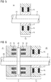
- FIG. 3 shows a driving machine for a body of water with three bearings 7, 9 and 10 for supporting a shaft 4.
- the operator-side bearing 8 of the shaft results from the bearings 9 and 10.
- All bearings 7, 9 and 10, and the electric machine 5 are located within a drive housing 27 of the nacelle drive, wherein the housing 2 of the nacelle drive also includes the drive housing 27.
- the drive housing 27 is attached via a shaft to the hull of a ship (not shown in this figure).
- a first bearing 9 and a second bearing 10 are provided, wherein the first bearing 9 is provided for receiving axial forces and the second bearing 10 is provided for receiving radial forces.
- FIG. 4 shows a cross section through the nacelle after FIG. 3 , Due to the cross section of the structure of the magnetic bearing 7 is illustrated.
- the magnetic bearing 7 has a first magnetic bearing segment 12, a second magnetic bearing segment 13, a third magnetic bearing segment 14 and a fourth magnetic bearing segment 15.
- the four magnetic bearing segments 12 to 15 are arranged in a circle.
- the magnetic bearing segments 12 to 15 have magnetic bearing coils 16 for generating a magnetic field.
- For control and / or control sensors 19 can be used. In the region of the sensors 19, cooling channels can also be provided for cooling the coils.
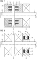
- FIG. 5 schematically shows the second bearing 10 according to FIG. 3 designed as a magnetic bearing 30.
- the magnetic bearing 9 has a radial magnetic bearing on a passive part 17 and an active part 18.
- the passive part 17 is seated on the shaft 4, which has an axis 20.
- the active part 18 has the magnetic bearing coil 16.
- FIG. 6 schematically shows the first bearing 9 and the second bearing 10 according to FIG. 3 , Both bearings are designed as magnetic bearings 31 and 32 and form a radial-axial magnetic bearing.
- the magnetic bearing 32 corresponds to the magnetic bearing 30 FIG. 5 ,
- the magnetic bearing 31 is positioned on the shaft 4 and has a first active part 21 and a second active part 22. These active parts 21 and 22 have magnetic bearing coils 16 and are in operative relation to the passive part 43 of the magnetic bearing 31st
- FIG. 7 schematically shows the first bearing 9 and the second bearing 10 according to FIG. 3 , unlike FIG. 6 the second bearing 10 after FIG. 7 is a mechanical bearing (eg a rolling bearing), which is symbolized by an "M" is.
- the construction after FIG. 7 So shows an axial magnetic bearing and, for example, a radial roller bearing.
- FIG. 8 schematically shows the first bearing 9 and the second bearing 10 according to FIG. 3 , unlike FIG. 6 the first camp 10 after FIG. 8 a mechanical bearing is (eg a rolling bearing).
- the element 43 can either be omitted (not shown here) or, for example, serve as a positioning aid for the mechanical bearings 35 and 36, which are provided in particular for receiving axial forces.
- the construction after FIG. 8 So shows axial roller bearings and a radial magnetic bearing.
Landscapes
- Engineering & Computer Science (AREA)
- General Engineering & Computer Science (AREA)
- Mechanical Engineering (AREA)
- Magnetic Bearings And Hydrostatic Bearings (AREA)
- Sliding-Contact Bearings (AREA)
- Connection Of Motors, Electrical Generators, Mechanical Devices, And The Like (AREA)
Description
- Die Erfindung betrifft eine Fahrmaschine für ein Gewässer mit einer drehbaren Welle, welche insbesondere eine Antriebswelle für zumindest einen Propeller ist.
- Beispiele für eine Fahrmaschine für ein Gewässer sind Containerschiffe, Passagierschiffe, Pod-Antriebe, Ruderpropeller, Frachter, U-Boote, etc. Gewässer sind beispielsweise Meere, Flüsse, Seen, usw. Derartige Fahrmaschinen für ein Gewässer, also insbesondere U-Boote, Schiffe und Boote sind mittels eines Propellers antreibbar, wobei der Propeller mit einer Antriebswelle mechanisch gekoppelt ist. Unter Fahrmaschine für ein Gewässer kann also ein Schwimmkörper, wie ein Schiff oder ein U-Boot, wie auch ein Teil davon verstanden werden. Dies ist beispielsweise eine Antriebsgondel.
- Die
EP 1 972 545 A1 zeigt beispielsweise eine Fahrmaschine für ein Gewässer, die als Pod-Antrieb für ein Schiff dient. Die Fahrmaschine für ein Gewässer weist insbesondere ein Unterwassergehäuse, das an dem Rumpf des Schiffes angeordnet ist, einen Propeller, der außerhalb des Gehäuses angeordnet ist, und eine Propellerwelle (also eine Antriebswelle), auf der der Propeller sitzt auf. Die Propellerwelle ist in dem Gehäuse gelagert. Das Gehäuse weist eine oder eine Vielzahl von Durchtrittsöffnungen auf, über welche die Propellerwelle aus dem Gehäuse heraus geführt ist. Innerhalb des Gehäuses ist beispielsweise ein Getriebe in Form eines Planetengetriebes angeordnet, das mit der Propellerwelle gekoppelt ist und ein Getriebegehäuse aufweist. Der Propeller kann auch direkt, also ohne Getriebe, angetrieben sein. Eine Wellendichtung dichtet die Durchtrittsöffnung gegen einen Eintritt von Flüssigkeit in das Gehäuse ab. Das Getriebe ist dabei insbesondere von der Wellendichtung beabstandet. Der Antrieb der Propellerwelle bzw. des Propellers über das gegebenenfalls verwendete Getriebe erfolgt durch eine Antriebsmotoreneinrichtung, die beispielsweise einen elektrischen Motor enthält. Dieser elektrische Motor ist bei einem Pod-Antrieb im Inneren des Gehäuses angeordnet. Ist der elektrische Motor außerhalb des Gehäuses im Schiffsrumpf angeordnet, so handelt es sich um einen Ruderpropeller. Bei einer Anordnung im Schiffsrumpf erfolgt der Antrieb der Propellerwelle bzw. des Propellers über eine Vertikalwelle, die von dem Schiffsrumpf in das Gehäuse geführt ist, und einem zwischen dem Getriebe und der Vertikalwelle angeordneten Tellerrad-Kegelrad-Getriebe. Ausführungen ohne Getriebe sind auch möglich.
Die Propellerwellenlagerung, also die Lagerung der Antriebswelle für eine Fahrmaschine für ein Gewässer wie ein Wasserfahrzeug, beispielsweise für einen azimutierenden elektrischen Antrieb, ist durch verschiedene Wälzlager, Gleitlager und/oder WälzGleitlageranordnungen und -ausführungen ausgestaltbar. - Die
WO 00/37308 A
Eine Lösung der Aufgabe ergibt sich bei einer Fahrmaschine für ein Gewässer nach Anspruch 1. Ausgestaltungen der Fahrmaschine für ein Gewässer ergeben sich nach den Ansprüchen 2 bis 13.
Eine Fahrmaschine für ein Gewässer, wie z.B. ein Containerschiff, ein Passagierschiffe, ein Pod-Antrieb, ein Frachter, ein U-Boot, ein Kompressor, weist einen Propeller und eine Welle auf. Die Fahrmaschine kann einen oder eine Vielzahl von Propellern aufweisen. Die Fahrmaschine kann auch eine oder eine Vielzahl von Wellen aufweisen. Die Welle ist insbesondere eine Antriebswelle, welche direkt ohne ein Getriebe oder indirekt mittels eines Getriebes eine elektrische Maschine, wie z.B. einen elektrischen Motor oder einen elektrischen Generator, mit dem Propeller koppelt. Die Kopplung ist insbesondere mechanisch, wobei die Welle insbesondere innerhalb eines Gehäuses, wie z.B. einer Gondel montiert am Schiffsrumpfes (Pod-Antrieb), gelagert ist. Das Lager zur Lagerung der Welle ist als ein Magnetlager ausgeführt. - Ein Vorteil der magnetischen Ausführung eines Lagers (Magnetlager) kann darin bestehen, dass es bezüglich mechanischer Komponenten verschleißfrei ausführbar ist. Eine Verschleißfreiheit ist beispielsweise bei Wälzlagern nicht gegeben.
- In einer Ausgestaltung der Fahrmaschine für ein Gewässer ergibt sich die Möglichkeit das Lager bzw. die Lager abhängig von den Erfordernissen, insbesondere des Betriebes eines Wasserfahrzeuges (Schiff, U-Boot, etc.), in ihrer Lagerwirkung zu verstärken, was insbesondere durch eine Hinzuschaltung weiterer Magnetlager möglich ist. So kann abhängig von der Belastung (insbesondere der Welle) ein Magnetlager aktiv sein oder eine Vielzahl von Magnetlagern. Zudem ist es auch möglich ein Magnetlager abhängig von der Belastung mit unterschiedlichen Stromstärken und/oder Spannungen zu beaufschlagen.
- Durch die Verwendung eines Magnetlagers ist auch ein reibungsarmer Betrieb der Lagerung der Welle möglich. Der reibungsärmere Betrieb wirkt sich verlustreduzierend aus. Zudem ist es möglich die abzuführende Lagerverlustwärme zu reduzieren.
- Das Magnetlager ist derart ausbildbar, dass keine Schmiermedien für die Lagerung benötigt werden, wodurch keine Schmiermedien in die Umwelt gelangen können. Gegebenenfalls ist es angezeigt für ein Fanglager ein Schmiermedium wie ein Fett oder ein Öl zu verwenden.
- Bei dem Magnetlager kann es auch vorteilhaft sein, dass durch dessen Einsatz und die daraus resultierende magnetische Lagerung geringere Vibrationen auftreten.
- In einer Ausgestaltung des Magnetlagers ist es ein aktives magnetisches Lager. Bei dem aktiven magnetischen Lager ist es möglich die Bestromung der Wicklungen des Magnetlagers zu regeln. Mittels des aktiven magnetischen Lagers kann beispielsweise eine Entkopplung der Schwingungen der Welle, insbesondere der Antriebswelle, also insbesondere der Propellerwelle, erreicht werden. An der Propellerwelle ist der Propeller mechanisch steif angekoppelt.
- In einer Ausgestaltung der Fahrmaschine für ein Gewässer weist diese zur Lagerung der Welle zumindest ein Magnetlager und zumindest ein mechanisches Lager auf. Das mechanische Lager ist beispielsweise ein Kugellager, ein Tonnenlager, ein Nadellager, etc. Durch die Verwendung zweier Lagertypen (mechanisches Lager und Magnetlager) ist es möglich deren jeweilige Vorteile zu kombinieren. Vorteile bzw. Nachteile können beispielsweise in folgenden Bereichen liegen: Preis, Platzbedarf, Belastbarkeit, Temperaturbeständigkeit, Notlaufeigenschaften, Lebensdauer, Lagerströme, usw.
- In einer Ausgestaltung der Fahrmaschine für ein Gewässer weist diese zur Lagerung der Welle ein erstes Lager und ein zweites Lager auf. Damit kann beispielsweise hohen Belastungen und/oder unterschiedlichen Belastungen Rechnung getragen werden.
- In einer Ausgestaltung der Fahrmaschine für ein Gewässer ist das erste Lager ausgeführt um Axialkräfte aufzunehmen. Das erste Lager ist folglich befähigt größere Axialkräfte als Radialkräfte aufzunehmen. Dabei richtet sich die Orientierung der Kräfte in axialer Richtung bzw. in radialer Richtung nach der Welle.
- In einer Ausgestaltung der Fahrmaschine für ein Gewässer ist das zweite Lager ausgeführt um Radialkräfte aufzunehmen. Das zweite Lager ist folglich befähigt größere Radialkräfte als Axialkräfte aufzunehmen. Auch dabei richtet sich die Orientierung der Kräfte in axialer Richtung bzw. in radialer Richtung nach der Welle.
- Durch eine Kombination von Lagern, welche durch ihren unterschiedlichen Aufbau überwiegend Axial- und/oder Radialkräfte aufnehmen können, kann eine für den jeweiligen Anwendungsfall optimierte Lagerkombination erreicht werden. Auch eine Kombination von drei oder mehr Lagern ist möglich.
- Auch eine Propellerwellenlagerung von azimutierenden elektrischen Antrieben für Wasserfahrzeuge (Pod-Antrieb) ist durch eine magnetische Lagerung optimierbar. Dies gelingt beispielsweise auch durch den Einsatz von Supraleitern. Ein mit Supraleiter ausgeführtes Magnetlager kann besonders hohe Kräfte aufnehmen und ermöglicht auch einen kompakten Aufbau. Azimutierende elektrische Antriebe sind bei Fahrmaschinen für ein Gewässer mit einer Antriebseinrichtung für eine schwimmende und/oder tauchende Einrichtung, wie z.B. ein Schiff oder eine Offshore-Plattform einsetzbar, wobei die Fahrmaschine für ein Gewässer, insbesondere horizontal und/oder vertikal bzw. insbesondere um ihre räumlich freie Achse drehbar, an einem Rumpf der schwimmenden oder tauchenden Einrichtung befestigt ist.
- Bei dem azimutierenden elektrischen Antrieb kann sowohl die Radiallagerung als auch die Axiallagerung der Propellerwelle und/oder des Motors als Magnetlager ausgeführt sein. Es sind aber auch Kombinationen von Wälzlagern (Radiallager oder Axiallager) mit Magnetlagern (Axiallager oder Radiallager) möglich.
- In einer Ausgestaltung der Fahrmaschine für ein Gewässer weist ein Getriebe zumindest ein Magnetlager auf. Mittels des Getriebes ist der Propeller mit dem Antrieb (z.B. eine elektrische Maschine) gekoppelt. Das Getriebe ist derart ausbildbar, dass beim Betrieb der Fahrmaschine für ein Gewässer die Drehzahl der elektrischen Maschine größer ist als die Drehzahl der Propellerwelle (z.B. 4 bis 5faches der Propellerdrehzahl). Als elektrische Maschine kann dann eine schnell laufende Maschine eingesetzt werden, die kleinere Abmessungen als eine mit der Propellerdrehzahl laufende Maschine hat. Dies gilt insbesondere bei einer Verwendung der Fahrmaschine für ein Gewässer als eine Antriebseinrichtung für eine schwimmende oder tauchende Einrichtung wie ein Unterseeboot (U-Boot). Die elektrische Maschine kann dabei als ein elektrischer Motor ausgebildet sein, der den Propeller antreibt. Als elektrische Motoren sind unterschiedlichste Elektromotoren wie z.B. Asynchron oder Synchronmotoren möglich, die durch Permanentmagnete oder ein Wicklungssystem erregt sein können, wobei diese auch in HTS (Hochtemperatur-Supraleiter)-Technik ausgeführt sein können. Die elektrische Maschine kann aber auch als ein Generator ausgebildet sein, der von dem Propeller angetrieben wird.
- In einer Ausgestaltung der Fahrmaschine für ein Gewässer ist die Welle mit einer elektrischen Maschine gekoppelt. Elektrische Maschinen sind im Vergleich zu Verbrennungskraftmaschinen wie einem Dieselmotor einfacher und exakter regelbar.
- In einer Ausgestaltung der Fahrmaschine für ein Gewässer ist das Getriebe mit der elektrischen Maschine und einem Propeller gekoppelt. Dabei kann das Magnetlager Kräfte aufnehmen, welche von dem Getriebe und/oder von der elektrischen Maschine herrühren.
- In einer Ausgestaltung der Fahrmaschine für ein Gewässer ist das Magnetlager und/oder ein Stromrichter des Magnetlagers gekühlt. Mittels des oder der Stromrichter sind Spulen des Magnetlagers bestrombar. Zur Steigerung der Effizienz kann einzeln oder in Kombination eine Kühlung von Stromrichter und Magnetlager vorgesehen sein.
- In einer Ausgestaltung der Fahrmaschine für ein Gewässer ist die Kühlung des Magnetlagers und/oder ein Stromrichter des Magnetlagers thermisch mit der Kühlung der elektrischen Maschine und/oder mit der Kühlung des Stromrichters für die elektrische Maschine gekoppelt. Durch gemeinsame Kühlkreisläufe kann der von der Kühlung beanspruchte Bauraum reduziert werden.
- In einer Ausgestaltung der Fahrmaschine für ein Gewässer weist das Magnetlager einen Supraleiter auf. Weist auch die elektrische Maschine einen Supraleiter auf, so kann durch eine gemeinsame Kühlung der Supraleiter von elektrischer Maschine und Magnetlager eine effiziente Kühlung realisiert werden.
- In einer Ausgestaltung der Fahrmaschine für ein Gewässer befindet sich die elektrische Maschine und das Magnetlager in einem Gehäuse, wobei das Gehäuse einen Gondelantrieb betrifft. Der Gondelantrieb ist als eine azimutierende elektrische Antriebseinheit ausbildbar.
- In einer Ausgestaltung der Fahrmaschine für ein Gewässer ist das Gehäuse in welchem sich die elektrische Maschine und das Magnetlager befinden ein Druckkörper, wie dieser bei Unterseebooten benötigt wird.
- Die Erfindung sowie weitere Ausgestaltungen der Erfindung werden im Folgenden anhand von Ausführungsbeispielen in den Figuren näher erläutert; dabei zeigt:
- FIG 1
- eine Fahrmaschine für ein Gewässer mit einer magnetisch gelagerten Welle;
- FIG 2
- eine Fahrmaschine für ein Gewässer mit einem gekühlten magnetischen Lager;
- FIG 3
- eine Fahrmaschine für ein Gewässer mit drei Lagern zur Lagerung einer Welle;
- FIG 4
- ein Magnetlager in einem Antriebsgehäuse;
- FIG 5
- ein Magnetlager für eine Welle;
- FIG 6
- eine erste Kombination von Lagern für eine Welle;
- FIG 7
- eine zweite Kombination von Lagern für eine Welle; und
- FIG 8
- eine dritte Kombination von Lagern für eine Welle.
- Die Darstellung nach
FIG 1 zeigt in vereinfachter und schematischer Darstellung eine Fahrmaschine für ein Gewässer 1 mit einem Schiffsrumpf 42 und angedeuteter Wasserlinie 11. Die Fahrmaschine für ein Gewässer 1 weist einen Gondelantrieb auf. In einem Gehäuse 2 des Gondelantriebes befindet sich eine elektrische Maschine 5, mittels derer über eine Welle 4 ein Propeller 3 antreibbar ist. Die Welle 4 ist durch ein antriebsseitiges Lager 7 und ein bedienseitiges Lager 8 innerhalb des Gehäuses 2 gelagert. Das antriebsseitige Lager 7 und oder das bedienseitige Lager 8 sind als Magnetlager ausgeführt. Durch den Einsatz von Magnetlagern können Reibungsverluste reduziert werden. - Die Darstellung nach
FIG 2 zeigt eine Fahrmaschine für ein Gewässer 1 ähnlich der nachFIG 1 . Die Fahrmaschine für ein Gewässer 1 weist zwischen der elektrischen Maschine 5 und dem Propeller 3 ein Getriebe 6 auf. Das antriebsseitige magnetische Lager 7 wird über einen Stromrichter 38 gespeist. Das bedienseitige magnetische Lager 8 wird über einen Stromrichter 37 gespeist. Die elektrische Maschine 5 wird über einen Stromrichter 39 gespeist. Zur Kühlung elektrischer Betriebsmittel wie z.B. Stromrichter ist eine Kühleinrichtung 23 vorgesehen. Mittels der Kühleinrichtung 23 lassen sich die Lager 7 und 8, die Stromrichter 37, 38 und 39 sowie die elektrische Maschine 5 kühlen, was durch gestrichelte Linien angedeutet ist. Zusätzlich kann auch das Getriebe mittels der Kühleinrichtung 23 gekühlt werden. - Die Darstellung nach
FIG 3 zeigt eine Fahrmaschine für ein Gewässer mit drei Lagern 7, 9 und 10 zur Lagerung einer Welle 4. Die bedienseitige Lagerung 8 der Welle ergibt sich durch die Lager 9 und 10. Alle Lager 7, 9 und 10, sowie die elektrische Maschine 5 befinden sich innerhalb eines Antriebsgehäuses 27 des Gondelantriebs, wobei das Gehäuse 2 des Gondelantriebs auch das Antriebsgehäuse 27 umfasst. Das Antriebsgehäuse 27 ist über einen Schaft am Rumpf eines Schiffes (in dieser Figur nicht dargestellt) angebracht. Bedienseitig sind ein erstes Lager 9 und ein zweites Lager 10 vorgesehen, wobei das erste Lager 9 zur Aufnahme von axialen Kräften vorgesehen ist und das zweite Lager 10 zur Aufnahme von radialen Kräften vorgesehen ist. - Die Darstellung nach
FIG 4 zeigt einen Querschnitt durch die Gondel nachFIG 3 . Durch den Querschnitt wird der Aufbau des Magnetlagers 7 verdeutlicht. Das Magnetlager 7 weist ein erstes Magnetlagersegment 12, ein zweites Magnetlagersegment 13, ein drittes Magnetlagersegment 14 und ein viertes Magnetlagersegment 15 auf. Die vier Magnetlagersegmente 12 bis 15 sind kreisförmig angeordnet. Die Magnetlagersegmente 12 bis 15 weisen Magnetlagerspulen 16 zur Erzeugung eines magnetischen Feldes auf. Zur Regelung und/oder Steuerung sind Sensoren 19 einsetzbar. Im Bereich der Sensoren 19 können zur Kühlung der Spulen auch Kühlkanäle vorgesehen sein. - Die Darstellung nach
FIG 5 zeigt schematisch das zweite Lager 10 gemäßFIG 3 ausgeführt als Magnetlager 30. Das Magnetlager 9 weist als Radial-Magnetlager ein Passivteil 17 und ein Aktivteil 18 auf. Das Passivteil 17 sitzt auf der Welle 4, welche eine Achse 20 hat. Das Aktivteil 18 weist die Magnetlagerspule 16 auf. - Die Darstellung nach
FIG 6 zeigt schematisch das erste Lager 9 und das zweite Lager 10 gemäßFIG 3 . Beide Lager sind als Magnetlager 31 und 32 ausgeführt und bilden ein Radial-Axial-Magnetlager. Das Magnetlager 32 entspricht dem Magnetlager 30 ausFigur 5 . Das Magnetlager 31 ist auf der Welle 4 positioniert und weist ein erstes Aktivteil 21 und ein zweites Aktivteil 22 auf. Diese Aktivteile 21 und 22 weisen Magnetlagerspulen 16 auf und stehen in Wirkbeziehung zum Passivteil 43 des Magnetlagers 31. - Die Darstellung nach
FIG 7 zeigt schematisch das erste Lager 9 und das zweite Lager 10 gemäßFIG 3 , wobei im Unterschied zuFIG 6 das zweite Lager 10 nachFIG 7 ein mechanisches Lager ist (z.B. ein Wälzlager), was durch ein "M" symbolisiert ist. Der Aufbau nachFIG 7 zeigt also ein Axial-Magnetlager und beispielsweise ein Radial-Wälzlager. - Die Darstellung nach
FIG 8 zeigt schematisch das erste Lager 9 und das zweite Lager 10 gemäßFIG 3 , wobei im Unterschied zuFIG 6 das erste Lager 10 nachFIG 8 ein mechanisches Lager ist (z.B. ein Wälzlager). Das Element 43 kann entweder entfallen (hier nicht dargestellt) oder beispielsweise als Positionierhilfe für die mechanischen Lager 35 und 36 dienen, welche insbesondere zur Aufnahme axialer Kräfte vorgesehen sind. Der Aufbau nachFIG 8 zeigt also beispielsweise Axial-Wälzlager und ein Radial-Magnetlager.
Claims (13)
- Fahrmaschine für ein Gewässer (1) mit einem Propeller (3) und einer Welle (4), die mit dem Propeller (3) gekoppelt ist, wobei der Propeller (3) mittels einer elektrischen Maschine (5) in einem Gehäuse (2) antreibbar ist, wobei die Welle (4) innerhalb des Gehäuses (2) eines POD-Antriebs (27) gelagert ist, wobei ein Lager (7,8) zur Lagerung der Welle (4) ein Magnetlager (30,31,32,33,34) ist, wobei die Lagerwirkung verstärkbar ist, wobei zur Lagerung der Welle (4) ein erstes Lager (9) und ein zweites Lager (10) vorgesehen ist, wobei das erste Lager (9) Axialkräfte aufnimmt, wobei das zweite Lager (10) Radialkräfte aufnimmt.
- Fahrmaschine für ein Gewässer (1) nach Anspruch 1,
dadurch gekennzeichnet , dass zur Verstärkung der Lagerwirkung weitere zuschaltbare Magnetlager (30, 31,32,33,34) vorgesehen sind. - Fahrmaschine für ein Gewässer (1) nach Anspruch 1 oder 2,
dadurch gekennzeichnet , dass das Magnetlager (30,31,32,33,34) abhängig von der Belastung mit unterschiedlichen Stromstärken und/oder Spannungen beaufschlagbar ist. - Fahrmaschine für ein Gewässer (1) nach einem der Ansprüche 1 bis 3, dadurch gekennzeichnet, dass das Magnetlager (30,31,32,33,34) ein aktives Lager ist, welches regelbar ist und Schwingungen der Antriebswelle entkoppelt.
- Fahrmaschine für ein Gewässer (1) nach einem der Ansprüche 1 bis 4, welche zur Lagerung der Welle (4) das Magnetlager (30,31,32,33,34) und ein mechanisches Lager (35) aufweist.
- Fahrmaschine für ein Gewässer (1) nach einem der Ansprüche 1 bis 5, wobei ein Getriebe (6) mittels zumindest eines Magnetlagers (30,31,32,33,34) gelagert ist.
- Fahrmaschine für ein Gewässer (1) nach einem der Ansprüche 1 bis 6, wobei die Welle (4) mit einer elektrischen Maschine (11) gekoppelt ist.
- Fahrmaschine für ein Gewässer (1) nach Anspruch 6 oder 7, wobei das Getriebe (6) mit der elektrischen Maschine (11) gekoppelt ist.
- Fahrmaschine für ein Gewässer (1) nach einem der Ansprüche 1 bis 8, wobei das Magnetlager (30,31,32,33,34) und/oder ein Stromrichter (24,25,26) des Magnetlagers gekühlt ist.
- Fahrmaschine für ein Gewässer (1) nach Anspruch 9, wobei die Kühlung des Magnetlagers (30,31,32,33,34) und/oder ein Stromrichter (24,25,26) des Magnetlagers thermisch mit der Kühlung der elektrischen Maschine (11) und/oder mit der Kühlung des Stromrichters (24,25,26) für die elektrische Maschine (11) gekoppelt ist.
- Fahrmaschine für ein Gewässer (1) nach einem der Ansprüche 1 bis 10, wobei das Magnetlager (30,31,32,33,34) einen Supraleiter (29) aufweist.
- Fahrmaschine für ein Gewässer (1) nach einem der Ansprüche 1 bis 11, wobei das Gehäuse (27) ein Gondelantrieb (40) ist.
- Fahrmaschine für ein Gewässer (1) nach einem der Ansprüche 1 bis 11, wobei das Gehäuse (27) ein Druckkörper (41) ist.
Applications Claiming Priority (2)
| Application Number | Priority Date | Filing Date | Title |
|---|---|---|---|
| DE102015212501.7A DE102015212501A1 (de) | 2015-07-03 | 2015-07-03 | Fahrmaschine für ein Gewässer mit einem Lager |
| PCT/EP2016/062321 WO2017005414A1 (de) | 2015-07-03 | 2016-06-01 | Fahrmaschine für ein gewässer mit einem lager |
Publications (2)
| Publication Number | Publication Date |
|---|---|
| EP3286443A1 EP3286443A1 (de) | 2018-02-28 |
| EP3286443B1 true EP3286443B1 (de) | 2019-03-13 |
Family
ID=56092927
Family Applications (1)
| Application Number | Title | Priority Date | Filing Date |
|---|---|---|---|
| EP16726107.2A Active EP3286443B1 (de) | 2015-07-03 | 2016-06-01 | Fahrmaschine für ein gewässer mit einem lager |
Country Status (3)
| Country | Link |
|---|---|
| EP (1) | EP3286443B1 (de) |
| DE (1) | DE102015212501A1 (de) |
| WO (1) | WO2017005414A1 (de) |
Families Citing this family (4)
| Publication number | Priority date | Publication date | Assignee | Title |
|---|---|---|---|---|
| CN108639302A (zh) * | 2018-05-15 | 2018-10-12 | 中国船舶科学研究中心(中国船舶重工集团公司第七0二研究所) | 一种船舶推进轴系用磁悬浮轴承综合控制装置 |
| CN110015395A (zh) * | 2018-11-29 | 2019-07-16 | 南京海琦娜游艇制造有限公司 | 船用磁悬浮舵系 |
| CN112265624A (zh) * | 2020-10-27 | 2021-01-26 | 罗广 | 一种磁动力螺旋桨结构 |
| DE102021111401A1 (de) * | 2021-05-03 | 2022-11-03 | Rosen Swiss Ag | Antriebsvorrichtung zum Antrieb eines Wasserfahrzeuges |
Family Cites Families (8)
| Publication number | Priority date | Publication date | Assignee | Title |
|---|---|---|---|---|
| DE9403202U1 (de) * | 1994-02-25 | 1995-03-23 | Siemens AG, 80333 München | Magnetische Lagerungseinrichtung mit Hoch-Tc-Supraleitermaterial |
| FI110599B (fi) * | 1998-12-22 | 2003-02-28 | Rolls Royce Oy Ab | Kääntyvä potkurilaite alusta, offshore-rakennetta tai vastaavaa varten |
| JP2003034292A (ja) * | 2001-07-19 | 2003-02-04 | Tomio Ueda | 推力軸受けを用いた電動スクリュウ |
| JP3963265B2 (ja) * | 2002-10-28 | 2007-08-22 | ナカシマプロペラ株式会社 | 船舶におけるポッド型推進器 |
| JP2006069369A (ja) * | 2004-09-02 | 2006-03-16 | Toshiba Mitsubishi-Electric Industrial System Corp | ポッド型電気推進装置 |
| JP3142137U (ja) | 2007-03-23 | 2008-06-05 | ショッテル ゲゼルシャフトミットベシュレンクターハフトゥング | 推進駆動装置 |
| CN201063491Y (zh) * | 2007-07-24 | 2008-05-21 | 刘新广 | 电磁力船 |
| KR101350514B1 (ko) * | 2012-02-03 | 2014-01-10 | 삼성중공업 주식회사 | 초전도 베어링을 구비한 이중 반전 프로펠러식 추진장치 및 이를 구비한 선박 |
-
2015
- 2015-07-03 DE DE102015212501.7A patent/DE102015212501A1/de not_active Ceased
-
2016
- 2016-06-01 EP EP16726107.2A patent/EP3286443B1/de active Active
- 2016-06-01 WO PCT/EP2016/062321 patent/WO2017005414A1/de not_active Ceased
Non-Patent Citations (1)
| Title |
|---|
| None * |
Also Published As
| Publication number | Publication date |
|---|---|
| DE102015212501A1 (de) | 2017-01-05 |
| EP3286443A1 (de) | 2018-02-28 |
| WO2017005414A1 (de) | 2017-01-12 |
Similar Documents
| Publication | Publication Date | Title |
|---|---|---|
| EP3286443B1 (de) | Fahrmaschine für ein gewässer mit einem lager | |
| EP2483146B1 (de) | Elektrische antriebswelle und fahrzeug mit einer derartigen elektrischen antriebswelle | |
| EP1449290B1 (de) | Schiffsantrieb | |
| DE112021008067T5 (de) | Elektroantrieb für ein Fahrzeug | |
| DE102009002264A1 (de) | Hybridantrieb eines Segelschiffes | |
| EP2993365B1 (de) | Propellergondelantrieb mit axiallager und radialgleitlager | |
| DE10322275A1 (de) | Kühlsystem für Elektrisches Antriebssystem mit Synchronmaschine mit Hochtemperatur-Supraleitender Feldwicklung für Propeller- und Jetantrieb mit besonders kleinen Durchmessern in schwimmenden Geräten | |
| DE69319620T2 (de) | Propellerantrieb | |
| EP2420443B1 (de) | Elektrischer Gondelantrieb für eine schwimmende Einrichtung mit interner Statorkühlung | |
| EP3289234B1 (de) | Fahrmaschine für ein gewässer mit einer azimutlagerung | |
| EP2605958A1 (de) | Verstellpropeller oder -repeller | |
| DE10143713B4 (de) | Elektrische Antriebseinrichtung für ein Schiff | |
| DE102004048754A1 (de) | Pod-Schiffsantrieb mit Getriebe | |
| EP2403750B1 (de) | Strömungsmaschine mit einem gehäuse mit erhöhter dichtheit | |
| DE3780719T2 (de) | Schiffsantriebsanlage mit hydraulischer uebertragung. | |
| WO2012084071A1 (de) | Schiffsantrieb | |
| DE10063338B4 (de) | Vorrichtung zum Antrieb eines Schiffes | |
| EP2226920B1 (de) | Blockheizkraftwerk-Aggregat mit einem Verbrennungskolbenmotor und einer elektrischen Maschine | |
| WO1999036312A2 (de) | Elektrische antriebseinrichtung für schiffe | |
| DE102012100175A1 (de) | Binnenschiff und Verfahren zum Betrieb eines Binnenschiffs | |
| EP2238019B1 (de) | Antrieb für ein wasserfahrzeug mit einem elektromotor | |
| WO2019057594A1 (de) | Azimutverstellung einer gondel | |
| DD279147A3 (de) | Wellengeneratoranlage zur stromerzeugung an bord von schiffen | |
| DE102004058259B4 (de) | Drehzahlvariabler Schiffsantrieb | |
| DE102004023481A1 (de) | Elektrisches Antriebssystem und elektrische Maschine |
Legal Events
| Date | Code | Title | Description |
|---|---|---|---|
| STAA | Information on the status of an ep patent application or granted ep patent |
Free format text: STATUS: THE INTERNATIONAL PUBLICATION HAS BEEN MADE |
|
| PUAI | Public reference made under article 153(3) epc to a published international application that has entered the european phase |
Free format text: ORIGINAL CODE: 0009012 |
|
| STAA | Information on the status of an ep patent application or granted ep patent |
Free format text: STATUS: REQUEST FOR EXAMINATION WAS MADE |
|
| 17P | Request for examination filed |
Effective date: 20171123 |
|
| AK | Designated contracting states |
Kind code of ref document: A1 Designated state(s): AL AT BE BG CH CY CZ DE DK EE ES FI FR GB GR HR HU IE IS IT LI LT LU LV MC MK MT NL NO PL PT RO RS SE SI SK SM TR |
|
| AX | Request for extension of the european patent |
Extension state: BA ME |
|
| DAV | Request for validation of the european patent (deleted) | ||
| DAX | Request for extension of the european patent (deleted) | ||
| GRAP | Despatch of communication of intention to grant a patent |
Free format text: ORIGINAL CODE: EPIDOSNIGR1 |
|
| STAA | Information on the status of an ep patent application or granted ep patent |
Free format text: STATUS: GRANT OF PATENT IS INTENDED |
|
| INTG | Intention to grant announced |
Effective date: 20181109 |
|
| GRAS | Grant fee paid |
Free format text: ORIGINAL CODE: EPIDOSNIGR3 |
|
| GRAA | (expected) grant |
Free format text: ORIGINAL CODE: 0009210 |
|
| STAA | Information on the status of an ep patent application or granted ep patent |
Free format text: STATUS: THE PATENT HAS BEEN GRANTED |
|
| AK | Designated contracting states |
Kind code of ref document: B1 Designated state(s): AL AT BE BG CH CY CZ DE DK EE ES FI FR GB GR HR HU IE IS IT LI LT LU LV MC MK MT NL NO PL PT RO RS SE SI SK SM TR |
|
| REG | Reference to a national code |
Ref country code: GB Ref legal event code: FG4D Free format text: NOT ENGLISH |
|
| REG | Reference to a national code |
Ref country code: CH Ref legal event code: EP Ref country code: AT Ref legal event code: REF Ref document number: 1108098 Country of ref document: AT Kind code of ref document: T Effective date: 20190315 |
|
| REG | Reference to a national code |
Ref country code: IE Ref legal event code: FG4D Free format text: LANGUAGE OF EP DOCUMENT: GERMAN |
|
| REG | Reference to a national code |
Ref country code: DE Ref legal event code: R096 Ref document number: 502016003755 Country of ref document: DE |
|
| REG | Reference to a national code |
Ref country code: NL Ref legal event code: MP Effective date: 20190313 |
|
| REG | Reference to a national code |
Ref country code: LT Ref legal event code: MG4D |
|
| PG25 | Lapsed in a contracting state [announced via postgrant information from national office to epo] |
Ref country code: SE Free format text: LAPSE BECAUSE OF FAILURE TO SUBMIT A TRANSLATION OF THE DESCRIPTION OR TO PAY THE FEE WITHIN THE PRESCRIBED TIME-LIMIT Effective date: 20190313 Ref country code: LT Free format text: LAPSE BECAUSE OF FAILURE TO SUBMIT A TRANSLATION OF THE DESCRIPTION OR TO PAY THE FEE WITHIN THE PRESCRIBED TIME-LIMIT Effective date: 20190313 Ref country code: NO Free format text: LAPSE BECAUSE OF FAILURE TO SUBMIT A TRANSLATION OF THE DESCRIPTION OR TO PAY THE FEE WITHIN THE PRESCRIBED TIME-LIMIT Effective date: 20190613 |
|
| PG25 | Lapsed in a contracting state [announced via postgrant information from national office to epo] |
Ref country code: BG Free format text: LAPSE BECAUSE OF FAILURE TO SUBMIT A TRANSLATION OF THE DESCRIPTION OR TO PAY THE FEE WITHIN THE PRESCRIBED TIME-LIMIT Effective date: 20190613 Ref country code: NL Free format text: LAPSE BECAUSE OF FAILURE TO SUBMIT A TRANSLATION OF THE DESCRIPTION OR TO PAY THE FEE WITHIN THE PRESCRIBED TIME-LIMIT Effective date: 20190313 Ref country code: RS Free format text: LAPSE BECAUSE OF FAILURE TO SUBMIT A TRANSLATION OF THE DESCRIPTION OR TO PAY THE FEE WITHIN THE PRESCRIBED TIME-LIMIT Effective date: 20190313 Ref country code: LV Free format text: LAPSE BECAUSE OF FAILURE TO SUBMIT A TRANSLATION OF THE DESCRIPTION OR TO PAY THE FEE WITHIN THE PRESCRIBED TIME-LIMIT Effective date: 20190313 Ref country code: HR Free format text: LAPSE BECAUSE OF FAILURE TO SUBMIT A TRANSLATION OF THE DESCRIPTION OR TO PAY THE FEE WITHIN THE PRESCRIBED TIME-LIMIT Effective date: 20190313 Ref country code: GR Free format text: LAPSE BECAUSE OF FAILURE TO SUBMIT A TRANSLATION OF THE DESCRIPTION OR TO PAY THE FEE WITHIN THE PRESCRIBED TIME-LIMIT Effective date: 20190614 |
|
| PG25 | Lapsed in a contracting state [announced via postgrant information from national office to epo] |
Ref country code: SK Free format text: LAPSE BECAUSE OF FAILURE TO SUBMIT A TRANSLATION OF THE DESCRIPTION OR TO PAY THE FEE WITHIN THE PRESCRIBED TIME-LIMIT Effective date: 20190313 Ref country code: EE Free format text: LAPSE BECAUSE OF FAILURE TO SUBMIT A TRANSLATION OF THE DESCRIPTION OR TO PAY THE FEE WITHIN THE PRESCRIBED TIME-LIMIT Effective date: 20190313 Ref country code: AL Free format text: LAPSE BECAUSE OF FAILURE TO SUBMIT A TRANSLATION OF THE DESCRIPTION OR TO PAY THE FEE WITHIN THE PRESCRIBED TIME-LIMIT Effective date: 20190313 Ref country code: ES Free format text: LAPSE BECAUSE OF FAILURE TO SUBMIT A TRANSLATION OF THE DESCRIPTION OR TO PAY THE FEE WITHIN THE PRESCRIBED TIME-LIMIT Effective date: 20190313 Ref country code: PT Free format text: LAPSE BECAUSE OF FAILURE TO SUBMIT A TRANSLATION OF THE DESCRIPTION OR TO PAY THE FEE WITHIN THE PRESCRIBED TIME-LIMIT Effective date: 20190713 Ref country code: RO Free format text: LAPSE BECAUSE OF FAILURE TO SUBMIT A TRANSLATION OF THE DESCRIPTION OR TO PAY THE FEE WITHIN THE PRESCRIBED TIME-LIMIT Effective date: 20190313 Ref country code: CZ Free format text: LAPSE BECAUSE OF FAILURE TO SUBMIT A TRANSLATION OF THE DESCRIPTION OR TO PAY THE FEE WITHIN THE PRESCRIBED TIME-LIMIT Effective date: 20190313 |
|
| PG25 | Lapsed in a contracting state [announced via postgrant information from national office to epo] |
Ref country code: PL Free format text: LAPSE BECAUSE OF FAILURE TO SUBMIT A TRANSLATION OF THE DESCRIPTION OR TO PAY THE FEE WITHIN THE PRESCRIBED TIME-LIMIT Effective date: 20190313 Ref country code: SM Free format text: LAPSE BECAUSE OF FAILURE TO SUBMIT A TRANSLATION OF THE DESCRIPTION OR TO PAY THE FEE WITHIN THE PRESCRIBED TIME-LIMIT Effective date: 20190313 |
|
| REG | Reference to a national code |
Ref country code: DE Ref legal event code: R097 Ref document number: 502016003755 Country of ref document: DE |
|
| PG25 | Lapsed in a contracting state [announced via postgrant information from national office to epo] |
Ref country code: IS Free format text: LAPSE BECAUSE OF FAILURE TO SUBMIT A TRANSLATION OF THE DESCRIPTION OR TO PAY THE FEE WITHIN THE PRESCRIBED TIME-LIMIT Effective date: 20190713 |
|
| PLBE | No opposition filed within time limit |
Free format text: ORIGINAL CODE: 0009261 |
|
| STAA | Information on the status of an ep patent application or granted ep patent |
Free format text: STATUS: NO OPPOSITION FILED WITHIN TIME LIMIT |
|
| PG25 | Lapsed in a contracting state [announced via postgrant information from national office to epo] |
Ref country code: DK Free format text: LAPSE BECAUSE OF FAILURE TO SUBMIT A TRANSLATION OF THE DESCRIPTION OR TO PAY THE FEE WITHIN THE PRESCRIBED TIME-LIMIT Effective date: 20190313 Ref country code: MC Free format text: LAPSE BECAUSE OF FAILURE TO SUBMIT A TRANSLATION OF THE DESCRIPTION OR TO PAY THE FEE WITHIN THE PRESCRIBED TIME-LIMIT Effective date: 20190313 |
|
| REG | Reference to a national code |
Ref country code: CH Ref legal event code: PL |
|
| 26N | No opposition filed |
Effective date: 20191216 |
|
| PG25 | Lapsed in a contracting state [announced via postgrant information from national office to epo] |
Ref country code: SI Free format text: LAPSE BECAUSE OF FAILURE TO SUBMIT A TRANSLATION OF THE DESCRIPTION OR TO PAY THE FEE WITHIN THE PRESCRIBED TIME-LIMIT Effective date: 20190313 |
|
| REG | Reference to a national code |
Ref country code: BE Ref legal event code: MM Effective date: 20190630 |
|
| PG25 | Lapsed in a contracting state [announced via postgrant information from national office to epo] |
Ref country code: TR Free format text: LAPSE BECAUSE OF FAILURE TO SUBMIT A TRANSLATION OF THE DESCRIPTION OR TO PAY THE FEE WITHIN THE PRESCRIBED TIME-LIMIT Effective date: 20190313 |
|
| PG25 | Lapsed in a contracting state [announced via postgrant information from national office to epo] |
Ref country code: IE Free format text: LAPSE BECAUSE OF NON-PAYMENT OF DUE FEES Effective date: 20190601 |
|
| PG25 | Lapsed in a contracting state [announced via postgrant information from national office to epo] |
Ref country code: LU Free format text: LAPSE BECAUSE OF NON-PAYMENT OF DUE FEES Effective date: 20190601 Ref country code: BE Free format text: LAPSE BECAUSE OF NON-PAYMENT OF DUE FEES Effective date: 20190630 Ref country code: LI Free format text: LAPSE BECAUSE OF NON-PAYMENT OF DUE FEES Effective date: 20190630 Ref country code: CH Free format text: LAPSE BECAUSE OF NON-PAYMENT OF DUE FEES Effective date: 20190630 |
|
| REG | Reference to a national code |
Ref country code: DE Ref legal event code: R081 Ref document number: 502016003755 Country of ref document: DE Owner name: SIEMENS ENERGY GLOBAL GMBH & CO. KG, DE Free format text: FORMER OWNER: SIEMENS AKTIENGESELLSCHAFT, 80333 MUENCHEN, DE |
|
| GBPC | Gb: european patent ceased through non-payment of renewal fee |
Effective date: 20200601 |
|
| PG25 | Lapsed in a contracting state [announced via postgrant information from national office to epo] |
Ref country code: GB Free format text: LAPSE BECAUSE OF NON-PAYMENT OF DUE FEES Effective date: 20200601 |
|
| PG25 | Lapsed in a contracting state [announced via postgrant information from national office to epo] |
Ref country code: CY Free format text: LAPSE BECAUSE OF FAILURE TO SUBMIT A TRANSLATION OF THE DESCRIPTION OR TO PAY THE FEE WITHIN THE PRESCRIBED TIME-LIMIT Effective date: 20190313 |
|
| PG25 | Lapsed in a contracting state [announced via postgrant information from national office to epo] |
Ref country code: HU Free format text: LAPSE BECAUSE OF FAILURE TO SUBMIT A TRANSLATION OF THE DESCRIPTION OR TO PAY THE FEE WITHIN THE PRESCRIBED TIME-LIMIT; INVALID AB INITIO Effective date: 20160601 Ref country code: MT Free format text: LAPSE BECAUSE OF FAILURE TO SUBMIT A TRANSLATION OF THE DESCRIPTION OR TO PAY THE FEE WITHIN THE PRESCRIBED TIME-LIMIT Effective date: 20190313 |
|
| PG25 | Lapsed in a contracting state [announced via postgrant information from national office to epo] |
Ref country code: MK Free format text: LAPSE BECAUSE OF FAILURE TO SUBMIT A TRANSLATION OF THE DESCRIPTION OR TO PAY THE FEE WITHIN THE PRESCRIBED TIME-LIMIT Effective date: 20190313 |
|
| REG | Reference to a national code |
Ref country code: AT Ref legal event code: MM01 Ref document number: 1108098 Country of ref document: AT Kind code of ref document: T Effective date: 20210601 |
|
| PG25 | Lapsed in a contracting state [announced via postgrant information from national office to epo] |
Ref country code: AT Free format text: LAPSE BECAUSE OF NON-PAYMENT OF DUE FEES Effective date: 20210601 |
|
| REG | Reference to a national code |
Ref country code: FI Ref legal event code: PCE Owner name: SIEMENS ENERGY GLOBAL GMBH & CO. KG |
|
| PGFP | Annual fee paid to national office [announced via postgrant information from national office to epo] |
Ref country code: FI Payment date: 20250624 Year of fee payment: 10 |
|
| PGFP | Annual fee paid to national office [announced via postgrant information from national office to epo] |
Ref country code: DE Payment date: 20250626 Year of fee payment: 10 |
|
| PGFP | Annual fee paid to national office [announced via postgrant information from national office to epo] |
Ref country code: FR Payment date: 20250624 Year of fee payment: 10 |
|
| PGFP | Annual fee paid to national office [announced via postgrant information from national office to epo] |
Ref country code: IT Payment date: 20250623 Year of fee payment: 10 |