EP3288408B1 - Abrollschuhe, abrollschuhentwicklungskit und verfahren - Google Patents
Abrollschuhe, abrollschuhentwicklungskit und verfahren Download PDFInfo
- Publication number
- EP3288408B1 EP3288408B1 EP16787085.6A EP16787085A EP3288408B1 EP 3288408 B1 EP3288408 B1 EP 3288408B1 EP 16787085 A EP16787085 A EP 16787085A EP 3288408 B1 EP3288408 B1 EP 3288408B1
- Authority
- EP
- European Patent Office
- Prior art keywords
- shoe
- rocker
- rocker piece
- sole
- kit
- Prior art date
- Legal status (The legal status is an assumption and is not a legal conclusion. Google has not performed a legal analysis and makes no representation as to the accuracy of the status listed.)
- Not-in-force
Links
Images


Classifications
-
- A—HUMAN NECESSITIES
- A43—FOOTWEAR
- A43B—CHARACTERISTIC FEATURES OF FOOTWEAR; PARTS OF FOOTWEAR
- A43B13/00—Soles; Sole-and-heel integral units
- A43B13/14—Soles; Sole-and-heel integral units characterised by the constructive form
- A43B13/143—Soles; Sole-and-heel integral units characterised by the constructive form provided with wedged, concave or convex end portions, e.g. for improving roll-off of the foot
- A43B13/145—Convex portions, e.g. with a bump or projection, e.g. 'Masai' type shoes
-
- A—HUMAN NECESSITIES
- A43—FOOTWEAR
- A43B—CHARACTERISTIC FEATURES OF FOOTWEAR; PARTS OF FOOTWEAR
- A43B13/00—Soles; Sole-and-heel integral units
- A43B13/02—Soles; Sole-and-heel integral units characterised by the material
- A43B13/12—Soles with several layers of different materials
-
- A—HUMAN NECESSITIES
- A43—FOOTWEAR
- A43B—CHARACTERISTIC FEATURES OF FOOTWEAR; PARTS OF FOOTWEAR
- A43B13/00—Soles; Sole-and-heel integral units
- A43B13/14—Soles; Sole-and-heel integral units characterised by the constructive form
- A43B13/143—Soles; Sole-and-heel integral units characterised by the constructive form provided with wedged, concave or convex end portions, e.g. for improving roll-off of the foot
-
- A—HUMAN NECESSITIES
- A43—FOOTWEAR
- A43B—CHARACTERISTIC FEATURES OF FOOTWEAR; PARTS OF FOOTWEAR
- A43B13/00—Soles; Sole-and-heel integral units
- A43B13/14—Soles; Sole-and-heel integral units characterised by the constructive form
- A43B13/16—Pieced soles
-
- A—HUMAN NECESSITIES
- A43—FOOTWEAR
- A43B—CHARACTERISTIC FEATURES OF FOOTWEAR; PARTS OF FOOTWEAR
- A43B13/00—Soles; Sole-and-heel integral units
- A43B13/14—Soles; Sole-and-heel integral units characterised by the constructive form
- A43B13/18—Resilient soles
- A43B13/187—Resiliency achieved by the features of the material, e.g. foam, non liquid materials
- A43B13/188—Differential cushioning regions
-
- A—HUMAN NECESSITIES
- A43—FOOTWEAR
- A43B—CHARACTERISTIC FEATURES OF FOOTWEAR; PARTS OF FOOTWEAR
- A43B13/00—Soles; Sole-and-heel integral units
- A43B13/14—Soles; Sole-and-heel integral units characterised by the constructive form
- A43B13/18—Resilient soles
- A43B13/189—Resilient soles filled with a non-compressible fluid, e.g. gel, water
-
- A—HUMAN NECESSITIES
- A43—FOOTWEAR
- A43B—CHARACTERISTIC FEATURES OF FOOTWEAR; PARTS OF FOOTWEAR
- A43B13/00—Soles; Sole-and-heel integral units
- A43B13/28—Soles; Sole-and-heel integral units characterised by their attachment, also attachment of combined soles and heels
- A43B13/32—Soles; Sole-and-heel integral units characterised by their attachment, also attachment of combined soles and heels by adhesives
-
- A—HUMAN NECESSITIES
- A43—FOOTWEAR
- A43B—CHARACTERISTIC FEATURES OF FOOTWEAR; PARTS OF FOOTWEAR
- A43B3/00—Footwear characterised by the shape or the use
- A43B3/0036—Footwear characterised by the shape or the use characterised by a special shape or design
- A43B3/0078—Footwear characterised by the shape or the use characterised by a special shape or design provided with logos, letters, signatures or the like decoration
-
- A—HUMAN NECESSITIES
- A43—FOOTWEAR
- A43B—CHARACTERISTIC FEATURES OF FOOTWEAR; PARTS OF FOOTWEAR
- A43B3/00—Footwear characterised by the shape or the use
- A43B3/0036—Footwear characterised by the shape or the use characterised by a special shape or design
- A43B3/0094—Footwear characterised by the shape or the use characterised by a special shape or design with means to differentiate between right and left shoe
-
- A—HUMAN NECESSITIES
- A43—FOOTWEAR
- A43B—CHARACTERISTIC FEATURES OF FOOTWEAR; PARTS OF FOOTWEAR
- A43B3/00—Footwear characterised by the shape or the use
- A43B3/24—Collapsible or convertible
- A43B3/246—Collapsible or convertible characterised by the sole
-
- A—HUMAN NECESSITIES
- A43—FOOTWEAR
- A43B—CHARACTERISTIC FEATURES OF FOOTWEAR; PARTS OF FOOTWEAR
- A43B7/00—Footwear with health or hygienic arrangements
- A43B7/32—Footwear with health or hygienic arrangements with shock-absorbing means
-
- B—PERFORMING OPERATIONS; TRANSPORTING
- B32—LAYERED PRODUCTS
- B32B—LAYERED PRODUCTS, i.e. PRODUCTS BUILT-UP OF STRATA OF FLAT OR NON-FLAT, e.g. CELLULAR OR HONEYCOMB, FORM
- B32B25/00—Layered products comprising a layer of natural or synthetic rubber
- B32B25/04—Layered products comprising a layer of natural or synthetic rubber comprising rubber as the main or only constituent of a layer, which is next to another layer of the same or of a different material
- B32B25/045—Layered products comprising a layer of natural or synthetic rubber comprising rubber as the main or only constituent of a layer, which is next to another layer of the same or of a different material of foam
-
- B—PERFORMING OPERATIONS; TRANSPORTING
- B32—LAYERED PRODUCTS
- B32B—LAYERED PRODUCTS, i.e. PRODUCTS BUILT-UP OF STRATA OF FLAT OR NON-FLAT, e.g. CELLULAR OR HONEYCOMB, FORM
- B32B25/00—Layered products comprising a layer of natural or synthetic rubber
- B32B25/10—Layered products comprising a layer of natural or synthetic rubber next to a fibrous or filamentary layer
-
- B—PERFORMING OPERATIONS; TRANSPORTING
- B32—LAYERED PRODUCTS
- B32B—LAYERED PRODUCTS, i.e. PRODUCTS BUILT-UP OF STRATA OF FLAT OR NON-FLAT, e.g. CELLULAR OR HONEYCOMB, FORM
- B32B27/00—Layered products comprising a layer of synthetic resin
- B32B27/06—Layered products comprising a layer of synthetic resin as the main or only constituent of a layer, which is next to another layer of the same or of a different material
- B32B27/065—Layered products comprising a layer of synthetic resin as the main or only constituent of a layer, which is next to another layer of the same or of a different material of foam
-
- B—PERFORMING OPERATIONS; TRANSPORTING
- B32—LAYERED PRODUCTS
- B32B—LAYERED PRODUCTS, i.e. PRODUCTS BUILT-UP OF STRATA OF FLAT OR NON-FLAT, e.g. CELLULAR OR HONEYCOMB, FORM
- B32B27/00—Layered products comprising a layer of synthetic resin
- B32B27/12—Layered products comprising a layer of synthetic resin next to a fibrous or filamentary layer
-
- B—PERFORMING OPERATIONS; TRANSPORTING
- B32—LAYERED PRODUCTS
- B32B—LAYERED PRODUCTS, i.e. PRODUCTS BUILT-UP OF STRATA OF FLAT OR NON-FLAT, e.g. CELLULAR OR HONEYCOMB, FORM
- B32B3/00—Layered products comprising a layer with external or internal discontinuities or unevennesses, or a layer of non-planar shape; Layered products comprising a layer having particular features of form
- B32B3/02—Layered products comprising a layer with external or internal discontinuities or unevennesses, or a layer of non-planar shape; Layered products comprising a layer having particular features of form characterised by features of form at particular places, e.g. in edge regions
-
- B—PERFORMING OPERATIONS; TRANSPORTING
- B32—LAYERED PRODUCTS
- B32B—LAYERED PRODUCTS, i.e. PRODUCTS BUILT-UP OF STRATA OF FLAT OR NON-FLAT, e.g. CELLULAR OR HONEYCOMB, FORM
- B32B3/00—Layered products comprising a layer with external or internal discontinuities or unevennesses, or a layer of non-planar shape; Layered products comprising a layer having particular features of form
- B32B3/10—Layered products comprising a layer with external or internal discontinuities or unevennesses, or a layer of non-planar shape; Layered products comprising a layer having particular features of form characterised by a discontinuous layer, i.e. formed of separate pieces of material
- B32B3/18—Layered products comprising a layer with external or internal discontinuities or unevennesses, or a layer of non-planar shape; Layered products comprising a layer having particular features of form characterised by a discontinuous layer, i.e. formed of separate pieces of material characterised by an internal layer formed of separate pieces of material which are juxtaposed side-by-side
-
- B—PERFORMING OPERATIONS; TRANSPORTING
- B32—LAYERED PRODUCTS
- B32B—LAYERED PRODUCTS, i.e. PRODUCTS BUILT-UP OF STRATA OF FLAT OR NON-FLAT, e.g. CELLULAR OR HONEYCOMB, FORM
- B32B3/00—Layered products comprising a layer with external or internal discontinuities or unevennesses, or a layer of non-planar shape; Layered products comprising a layer having particular features of form
- B32B3/26—Layered products comprising a layer with external or internal discontinuities or unevennesses, or a layer of non-planar shape; Layered products comprising a layer having particular features of form characterised by a particular shape of the outline of the cross-section of a continuous layer; characterised by a layer with cavities or internal voids ; characterised by an apertured layer
- B32B3/263—Layered products comprising a layer with external or internal discontinuities or unevennesses, or a layer of non-planar shape; Layered products comprising a layer having particular features of form characterised by a particular shape of the outline of the cross-section of a continuous layer; characterised by a layer with cavities or internal voids ; characterised by an apertured layer characterised by a layer having non-uniform thickness
-
- B—PERFORMING OPERATIONS; TRANSPORTING
- B32—LAYERED PRODUCTS
- B32B—LAYERED PRODUCTS, i.e. PRODUCTS BUILT-UP OF STRATA OF FLAT OR NON-FLAT, e.g. CELLULAR OR HONEYCOMB, FORM
- B32B3/00—Layered products comprising a layer with external or internal discontinuities or unevennesses, or a layer of non-planar shape; Layered products comprising a layer having particular features of form
- B32B3/26—Layered products comprising a layer with external or internal discontinuities or unevennesses, or a layer of non-planar shape; Layered products comprising a layer having particular features of form characterised by a particular shape of the outline of the cross-section of a continuous layer; characterised by a layer with cavities or internal voids ; characterised by an apertured layer
- B32B3/30—Layered products comprising a layer with external or internal discontinuities or unevennesses, or a layer of non-planar shape; Layered products comprising a layer having particular features of form characterised by a particular shape of the outline of the cross-section of a continuous layer; characterised by a layer with cavities or internal voids ; characterised by an apertured layer characterised by a layer formed with recesses or projections, e.g. hollows, grooves, protuberances, ribs
-
- B—PERFORMING OPERATIONS; TRANSPORTING
- B32—LAYERED PRODUCTS
- B32B—LAYERED PRODUCTS, i.e. PRODUCTS BUILT-UP OF STRATA OF FLAT OR NON-FLAT, e.g. CELLULAR OR HONEYCOMB, FORM
- B32B5/00—Layered products characterised by the non- homogeneity or physical structure, i.e. comprising a fibrous, filamentary, particulate or foam layer; Layered products characterised by having a layer differing constitutionally or physically in different parts
- B32B5/02—Layered products characterised by the non- homogeneity or physical structure, i.e. comprising a fibrous, filamentary, particulate or foam layer; Layered products characterised by having a layer differing constitutionally or physically in different parts characterised by structural features of a fibrous or filamentary layer
-
- B—PERFORMING OPERATIONS; TRANSPORTING
- B32—LAYERED PRODUCTS
- B32B—LAYERED PRODUCTS, i.e. PRODUCTS BUILT-UP OF STRATA OF FLAT OR NON-FLAT, e.g. CELLULAR OR HONEYCOMB, FORM
- B32B5/00—Layered products characterised by the non- homogeneity or physical structure, i.e. comprising a fibrous, filamentary, particulate or foam layer; Layered products characterised by having a layer differing constitutionally or physically in different parts
- B32B5/18—Layered products characterised by the non- homogeneity or physical structure, i.e. comprising a fibrous, filamentary, particulate or foam layer; Layered products characterised by having a layer differing constitutionally or physically in different parts characterised by features of a layer of foamed material
-
- B—PERFORMING OPERATIONS; TRANSPORTING
- B32—LAYERED PRODUCTS
- B32B—LAYERED PRODUCTS, i.e. PRODUCTS BUILT-UP OF STRATA OF FLAT OR NON-FLAT, e.g. CELLULAR OR HONEYCOMB, FORM
- B32B5/00—Layered products characterised by the non- homogeneity or physical structure, i.e. comprising a fibrous, filamentary, particulate or foam layer; Layered products characterised by having a layer differing constitutionally or physically in different parts
- B32B5/22—Layered products characterised by the non- homogeneity or physical structure, i.e. comprising a fibrous, filamentary, particulate or foam layer; Layered products characterised by having a layer differing constitutionally or physically in different parts characterised by the presence of two or more layers which are next to each other and are fibrous, filamentary, formed of particles or foamed
- B32B5/24—Layered products characterised by the non- homogeneity or physical structure, i.e. comprising a fibrous, filamentary, particulate or foam layer; Layered products characterised by having a layer differing constitutionally or physically in different parts characterised by the presence of two or more layers which are next to each other and are fibrous, filamentary, formed of particles or foamed one layer being a fibrous or filamentary layer
- B32B5/245—Layered products characterised by the non- homogeneity or physical structure, i.e. comprising a fibrous, filamentary, particulate or foam layer; Layered products characterised by having a layer differing constitutionally or physically in different parts characterised by the presence of two or more layers which are next to each other and are fibrous, filamentary, formed of particles or foamed one layer being a fibrous or filamentary layer another layer next to it being a foam layer
-
- B—PERFORMING OPERATIONS; TRANSPORTING
- B32—LAYERED PRODUCTS
- B32B—LAYERED PRODUCTS, i.e. PRODUCTS BUILT-UP OF STRATA OF FLAT OR NON-FLAT, e.g. CELLULAR OR HONEYCOMB, FORM
- B32B5/00—Layered products characterised by the non- homogeneity or physical structure, i.e. comprising a fibrous, filamentary, particulate or foam layer; Layered products characterised by having a layer differing constitutionally or physically in different parts
- B32B5/22—Layered products characterised by the non- homogeneity or physical structure, i.e. comprising a fibrous, filamentary, particulate or foam layer; Layered products characterised by having a layer differing constitutionally or physically in different parts characterised by the presence of two or more layers which are next to each other and are fibrous, filamentary, formed of particles or foamed
- B32B5/24—Layered products characterised by the non- homogeneity or physical structure, i.e. comprising a fibrous, filamentary, particulate or foam layer; Layered products characterised by having a layer differing constitutionally or physically in different parts characterised by the presence of two or more layers which are next to each other and are fibrous, filamentary, formed of particles or foamed one layer being a fibrous or filamentary layer
- B32B5/26—Layered products characterised by the non- homogeneity or physical structure, i.e. comprising a fibrous, filamentary, particulate or foam layer; Layered products characterised by having a layer differing constitutionally or physically in different parts characterised by the presence of two or more layers which are next to each other and are fibrous, filamentary, formed of particles or foamed one layer being a fibrous or filamentary layer another layer next to it also being fibrous or filamentary
-
- B—PERFORMING OPERATIONS; TRANSPORTING
- B32—LAYERED PRODUCTS
- B32B—LAYERED PRODUCTS, i.e. PRODUCTS BUILT-UP OF STRATA OF FLAT OR NON-FLAT, e.g. CELLULAR OR HONEYCOMB, FORM
- B32B5/00—Layered products characterised by the non- homogeneity or physical structure, i.e. comprising a fibrous, filamentary, particulate or foam layer; Layered products characterised by having a layer differing constitutionally or physically in different parts
- B32B5/22—Layered products characterised by the non- homogeneity or physical structure, i.e. comprising a fibrous, filamentary, particulate or foam layer; Layered products characterised by having a layer differing constitutionally or physically in different parts characterised by the presence of two or more layers which are next to each other and are fibrous, filamentary, formed of particles or foamed
- B32B5/32—Layered products characterised by the non- homogeneity or physical structure, i.e. comprising a fibrous, filamentary, particulate or foam layer; Layered products characterised by having a layer differing constitutionally or physically in different parts characterised by the presence of two or more layers which are next to each other and are fibrous, filamentary, formed of particles or foamed at least two layers being foamed and next to each other
-
- B—PERFORMING OPERATIONS; TRANSPORTING
- B32—LAYERED PRODUCTS
- B32B—LAYERED PRODUCTS, i.e. PRODUCTS BUILT-UP OF STRATA OF FLAT OR NON-FLAT, e.g. CELLULAR OR HONEYCOMB, FORM
- B32B7/00—Layered products characterised by the relation between layers; Layered products characterised by the relative orientation of features between layers, or by the relative values of a measurable parameter between layers, i.e. products comprising layers having different physical, chemical or physicochemical properties; Layered products characterised by the interconnection of layers
- B32B7/02—Physical, chemical or physicochemical properties
- B32B7/022—Mechanical properties
-
- B—PERFORMING OPERATIONS; TRANSPORTING
- B32—LAYERED PRODUCTS
- B32B—LAYERED PRODUCTS, i.e. PRODUCTS BUILT-UP OF STRATA OF FLAT OR NON-FLAT, e.g. CELLULAR OR HONEYCOMB, FORM
- B32B7/00—Layered products characterised by the relation between layers; Layered products characterised by the relative orientation of features between layers, or by the relative values of a measurable parameter between layers, i.e. products comprising layers having different physical, chemical or physicochemical properties; Layered products characterised by the interconnection of layers
- B32B7/04—Interconnection of layers
- B32B7/12—Interconnection of layers using interposed adhesives or interposed materials with bonding properties
-
- B—PERFORMING OPERATIONS; TRANSPORTING
- B32—LAYERED PRODUCTS
- B32B—LAYERED PRODUCTS, i.e. PRODUCTS BUILT-UP OF STRATA OF FLAT OR NON-FLAT, e.g. CELLULAR OR HONEYCOMB, FORM
- B32B2250/00—Layers arrangement
- B32B2250/44—Number of layers variable across the laminate
-
- B—PERFORMING OPERATIONS; TRANSPORTING
- B32—LAYERED PRODUCTS
- B32B—LAYERED PRODUCTS, i.e. PRODUCTS BUILT-UP OF STRATA OF FLAT OR NON-FLAT, e.g. CELLULAR OR HONEYCOMB, FORM
- B32B2266/00—Composition of foam
- B32B2266/02—Organic
- B32B2266/0214—Materials belonging to B32B27/00
-
- B—PERFORMING OPERATIONS; TRANSPORTING
- B32—LAYERED PRODUCTS
- B32B—LAYERED PRODUCTS, i.e. PRODUCTS BUILT-UP OF STRATA OF FLAT OR NON-FLAT, e.g. CELLULAR OR HONEYCOMB, FORM
- B32B2437/00—Clothing
- B32B2437/02—Gloves, shoes
Definitions
- the subject matter discussed herein relates generally to rocker shoes for treatment of foot and ankle problems, and is particularly concerned with a rocker shoe development kit and method for construction of rocker shoes for medical applications.
- Rocker modifications to shoes are commonly prescribed for treatment of numerous foot and ankle problems.
- the prescriptions are based primarily on theory and clinical experience, with limited science and validation (see “ The Biomechanics and clinical efficacy of footwear adapted with rocker profiles- Evidence in the literature” by Hutchins, S. et al., The Foot, 19:165-170, 2009 ).
- Current rocker shoe design is a clinical art, with minimal guidelines for clinicians to follow for specific shoe designs.
- Rocker shoes are prescribed for a variety of medical reasons, including redistribution of plantar pressures away from bony prominences of the foot (e.g. for persons with sensation loss and risk of skin breakdown), and reduction of foot and ankle movements (e.g. for persons with pain at the tibiotalar or metatarsophalangeal joints).
- US2010263228 (A1 ) discloses a sole for shoes enabling exchange of a shock-absorbing member, in which a shock-absorbing member can be exchanged with one suited to each situation whenever necessary depending on the state of a wearer's feet, the condition of a road surface, the walking motion, or the like even in a state where a shoe has been manufactured and is worn by the wearer, thereby further improving convenience in use.
- the shoe sole 100 includes the hollow space portion formed laterally at the inside thereof, any one selected from the group consisting of the air bag, the cushion member and the spring can be exchangeably employed as the shock-absorbing member so to be suited to each situation whenever necessary depending on the state of a wearer's feet, the condition of a road surface, the walking motion, or the like, thereby further improving convenience in use.
- the present disclosure provides a rocker shoe construction kit as detailed in claim 1, a rocker shoe according to claim 12, and a method of construction of a rocker shoe according to claim 14.
- Advantageous features are provided in dependent claims.
- the development kit also comprises a pair of shoe uppers each having a sole with a lower or plantar surface which has a flat surface portion extending along at least part of the length of the sole from the heel towards the toe of the shoe upper for securing to the upper surface of the rocker piece.
- sole portions of an existing shoe may be cut to form the flat surface portion for attachment to the rocker member.
- the rocker member may be oversized in the transverse plane such that after attachment to the shoe, the excess transverse rocker member material may be ground down to match the transverse profile of the shoe.
- the development kit also includes a dual last jig for holding a pair of shoes while the soles are cut to form the flat surface portions.
- the sole of the existing shoe uppers and the rocker piece or member are provided with indicators for lining up the rocker piece with the ankle region of the shoe, i.e. the region where the ankle joint is expected to be located for persons with normal anatomy.
- a pair of rocker shoes are provided which are designed so that little or no motion is produced at the ankle during the single-limb support phase of walking, i.e. the period of highest compressive load.
- Each rocker shoe has a heel, a toe, and a sole with a lower rocker surface extending from the heel towards the toe.
- the rocker surface may extend over the entire plantar surface of the shoe or may terminate at a predetermined location short of the toe of the shoe.
- the rocker surface terminates at a location corresponding to the first metatarsal phalangeal joint, which is generally located at around 75 to 80% of the length of the sole from the heel.
- the sole is formed from multiple layers attached to the existing shoe sole, comprising a rocker piece of rigid or semi-rigid material secured to the lower surface of the existing shoe sole and extending from the heel towards the toe of the shoe, a cushioning or intermediate layer secured to the lower surface of the rocker piece and following the shape of the rocker surface, and a tread layer secured to the lower surface of the cushioning layer and conforming to the shape of the cushioning layer.
- the rocker surface is curved and has a predetermined rocker radius dependent on a wearer's height.
- the rocker piece may cover the entire plantar surface of the shoe or may cover only a portion of the plantar surface to produce a lower profile or lower height design.
- one or more inserts of different material from the rocker piece may be mounted in one or more cut-outs in the lower surface of the rocker piece between the rocker piece and cushioning layer.
- the inserts may be of highly damped material or comprise enclosures filled with a shear-thickening fluid or shear-thinning fluid.
- the insert is designed to deform slowly into a flattened geometry during static loads associated with standing.
- inserts containing shear-thinning fluids may comprise the intermediate layer, and the shear-thinning fluid is designed to be stable under static loads and more fluid during dynamic loading.
- kits for construction of rocker shoes for medical applications and with rocker shoes which may be produced with the kits or by other means
- a similar kit may be designed for manufacturing other types of footwear intended for non-custom medical and consumer markets.
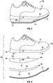
- FIG. 1 illustrates one embodiment of a rocker shoe development kit or assembly 10 which comprises a prepared shoe upper 12, a rocker piece or rocker member 14, a cushioning layer 15, and a tread layer 16.
- the kit includes a pair of shoe uppers and corresponding rocker members, cushioning layers, and tread layers for a pair of right and left rocker shoes.
- this embodiment includes a pre-prepared shoe upper 12, in an alternative embodiment the kit may comprise only the rocker members 14 cushioning layers 15, and tread layers 16 for a pair of shoes, and the shoe uppers may be prepared as needed from shoes which are cut to form a flat surface portion on the sole for attachment of the shoe kit parts.
- FIG. 10 illustrates one embodiment of a rocker shoe development kit or assembly 10 which comprises a prepared shoe upper 12, a rocker piece or rocker member 14, a cushioning layer 15, and a tread layer 16.
- the kit includes a pair of shoe uppers and corresponding rocker members, cushioning layers, and tread layers for a pair of right and left rocker shoes.
- this embodiment includes
- FIG. 1 illustrates one example of a kit for producing a predetermined rocker profile as illustrated in FIG. 3 when assembled, but it will be understood that the same basic kit may be provided with rocker pieces of different shapes to produce different rocker profiles, and an example of an alternative rocker profile kit is provided in FIGS. 4 and 5 , as described in more detail below.
- Rocker kits of various different profiles may be provided for different prescribed ankle angular motion, so that the medical professional can choose the kit which has the appropriate rocker profile for a specific patient.
- Embodiments of this invention include kits in a range of different rocker shoe profiles so that an appropriate kit can be selected for a patient based on height and the desired rocker motion.
- the kit may also include a dual last jig 18 as illustrated in FIG. 2A .
- the jig 18 comprises two foot-shaped forms 20 connected together by connecting rod 22, with the soles of the foot forms extending parallel to one another.
- foot forms 20 may be replaced by adjustable size shoe lasts so that different size shoes may be pre-cut on the jig.
- the jig allows a pair of shoes to be secured so that the bottom soles of the two shoes are perpendicular with the table top of a band saw and parallel with the band saw blade.
- a pair of shoes 24 are secured on the respective prosthetic feet or lasts 20 as illustrated in FIG. 2B .
- the sole 26 of each shoe is then cut with the band saw to form a flat surface portion or base 28 (see FIG. 2C ) for connection of the structural rocker pieces 14 to the respective soles.
- each prepared shoe upper 12 has a sole 26 with a flat surface portion 28 extending from the heel 29 along at least part of the length of the shoe up to a predetermined position 30 short of the toe end 32 of the shoe.
- flat surface portion 28 extends up to 75% or 80% of the length of the shoe and position 30 may be at a location which at least substantially corresponds to the first metatarsal phalangeal joint of the toes of a wearer of the shoe.
- a marker or indicator line 34 is provided on one or both of the opposite side faces of the sole at a position aligned with the ankle region of the shoe, i.e. the region where the ankle joint is expected to be located for persons with normal anatomy.
- rocker piece or member 14 is made of a rigid or semi-rigid non-deforming material such as plastic, hard foam, hard crepe, or the like.
- the material is selected to be relatively lightweight to keep the shoes light in weight.
- the rocker piece was made from Ultem® plastic material, but other materials with similar properties may be used in alternative embodiments.
- the rocker piece has a profile or outer periphery designed to follow the profile of the planter surface of the shoe sole up to break point 36 at the tip of the rocker piece. Upper surface 38 is flat, and the lower surface 40 in this embodiment is also flat up to point 42, after which an upward taper 44 extends from point 42 to break point 36.
- the rear end 45 of rocker piece 14 has a slight inward taper.
- a marker or indicator line 46 is provided on one or both of the opposite side faces 48 of the rocker piece for proper alignment of the rocker surface with the ankle region of the shoe, i.e. at the location on the rocker piece which is intended for alignment with the region where the ankle joint is expected to be located for persons with normal anatomy when the shoe is worn.
- the rocker piece has transverse plane dimensions which exactly match those of the flat-bottomed shoe upper up to a position close to or at break point or the forward end 30 of the flat lower surface of the sole, and covers the portion of the plantar surface of the sole from the heel up to break point 36, which is positioned slightly rear of forward end 30 of the flat sole portion in the embodiment of Figs. 1 and 3 .
- the rocker piece may cover more of the plantar surface, up to the entire plantar surface of the sole of the shoe.
- the line 46 on the rocker piece is aligned with line 34 on the corresponding side face of the shoe sole of a prepared shoe upper 12 before securing the rocker piece 14 to the flat lower surface portion 28 of the shoe sole with glue or the like. Any part of the rocker piece which then extends beyond the heel of the shoe is ground away in the transverse plane, without any modification to the plantar features of the rocker piece. Cushioning layer 15 is then attached to the lower surface of the rocker piece, and the tread layer 16 is attached over the lower surface of the cushioning layer and exposed forward end portion of the shoe sole.
- cushioning layer 15 is made of a suitable cushioning material such as soft crepe or foam and is designed to cover the entire lower surface 40 of rocker piece 14.
- Layer 15 is of uniform thickness and has a forward end taper 50 to match the selected rocker profile.
- the layer 15 also matches the rocker piece and flat lower surface of the shoe in transverse plane shape, and is designed to be attached to the lower surface of rocker piece 14 by adhesive or the like.
- a flat upper end face 35 is adhered to the forward end of the flat sole portion of the shoe in front of break point 36 of rocker piece 14, as seen in Fig. 3 .
- Tread layer 16 comprises a piece of rubber tread designed to be glued onto the bottom of the crepe or cushioning layer 15 and forward end portion of the sole of the shoe, up to the toe, and covers the entire lower surface of the shoe and attached rocker piece and cushioning layer.
- the rubber tread protects the cushioning layer from premature breakdown and is also designed to provide an appropriate level of friction between the shoe and the walking surface.
- FIG. 3 illustrates the assembled rocker shoe 52. Unlike a conventional rocker shoe, the rocker piece in this shoe does not extend to the toe, but terminates at or close to the location of the first metatarsal phalangeal joint of a person wearing the shoe. This reduces the height of the rocker shoe for improved cosmetics and safety.
- a shoe company may provide rocker shoe assembly kits of different shoe sizes having a variety of shoe designs to accommodate the cosmetic preference of various users, including both right and left shoe uppers along with corresponding right and left rocker pieces, cushioning layers, and tread material layers.
- flat and consistent sole portions 28 are formed on every shoe upper for simple modification by the shoe technician to add the corresponding rocker piece, cushioning layer and tread layer. Every shoe upper may be provided with indicator line 34 aligned with the expected ankle joint position for correct alignment of the shoe with the rocker piece to be attached under the sole. In this case, the dual-last jig is not necessary.
- the kit of the above embodiment is designed to provide a rocker surface which terminates short of the toe end of the shoe.
- the rigid or semi-rigid rocker pieces may cover the entire plantar surface of the shoe sole from the heel to the toe of the shoe, along with the underlying cushioning and tread layers. It will be understood that kits will be provided in a range of different shoe sizes (length and width).
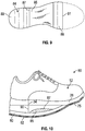
- FIGS. 4 to 6 illustrate another embodiment of a rocker shoe 55 ( FIG. 6 ) and rocker shoe assembly kit 56 ( FIG. 4 and 5 ).
- the shoe upper 12 in this embodiment is the same as in the previous embodiment, and like reference numbers are used for like parts as appropriate.
- Kit 56 also comprises rocker piece 58, cushioning layer 60, and tread layer 62, which are of the same or similar materials to the corresponding parts of the kit of the previous embodiment, but of different shapes.
- the upper surface 59 of rocker piece 58 is flat.
- the rocker piece 58 has a curved, convex lower surface 64 extending from rear end 65 up to break point 66.
- An indicator line 68 is provided for alignment with ankle joint indicator line 34 on the shoe upper 12.
- the rocker piece covers most of the flat lower surface portion of sole 26 with break point 66 spaced from the forward end of the flat surface portion of the sole (see FIG. 5 ), terminating short of the toe to reduce overall height of the rocker shoe 55.
- the curved rocker piece may extend over the entire length of the shoe.
- the cushioning layer 60 is of any suitable cushioning material such as crepe or plastic foam material, as in the previous embodiment, and may be formed into a curved shape matching the curvature of the lower surface 64 of rocker piece 58, with a flat, upwardly facing forward end portion 70.
- Forward end portion 70 is designed to be adhered to the forward end of the flat lower surface portion 28 of sole 26 in front of the forward end of rocker piece 58 when the parts are assembled as in FIG. 6 .
- Tread layer 62 forms a lower tread surface 72 of rocker shoe 55, and is secured over the lower surface 64 of cushioning layer 60 with a forward portion 75 secured to the curved sole portion of the shoe upper between the forward end of the cushioning layer and the toe 32 of the shoe.
- layer 60 is of deformable material which adopts the curvature of the lower surface of rocker piece 58 when adhered to that surface.
- the parts are glued together in turn using a suitable adhesive, as described above in connection with FIGS. 1 and 3 .
- Rocker shoe 55 is designed to reduce ankle motion during walking, particularly during the part of a walking gait cycle when forces on the leg are highest. This is during the single-limb support portion of a walking step when the foot engages the ground at the heel and rocks onto the toes.
- FIG. 7 is a graphical plot which compares ankle range of motion variation over a gait cycle for a wearer when wearing a normal shoe (black circles) and when wearing the rocker shoe (black squares). The single-limb stance or support phase of the gait cycle is between the vertical lines. In some embodiments, compared to the normal shoe (upper line between vertical lines), the rocker shoe of FIG.
- the rocker shoes of FIG. 6 reduces ankle range of motion from approximately 12 degrees to less than five degrees during the period of the gait cycle when forces on the ankle are highest.
- the rocker shoes of FIG. 6 reduce ankle motion or produce natural immobilization of the ankle during the stance limb support time when the forces on the leg are highest, potentially reducing ankle pain.
- the rocker radius of the rocker shoe of FIG. 6 ranges from 10%-25% of a patient's height, with a median of around 16% of the patient's height. Kits of different rocker radius may be provided for patients of different heights or height ranges.
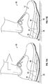
- FIG. 10 illustrates an embodiment of a modified rocker shoe 80 which is similar to the shoe of FIG. 6 , but has an insert 85 designed to produce more stability during standing.
- FIG. 8 and 9 illustrate parts of a kit 82 which may be used for making the shoe of FIG. 10 .
- the shoe upper 12, cushioning layer 60, and tread layer 62 of the kit 82 are identical to the corresponding parts of kit 56 of FIG. 4 , and like reference numbers are used for like parts as appropriate.
- the rocker piece 58 of the previous embodiment is replaced by modified rocker piece 84 and insert 85.
- Rocker piece 84 is substantially the same shape as rocker piece 58, but part of the curved lower surface of the rocker piece has a cut out or arcuate recess 87 in which insert 85 is secured.
- Insert 85 has a lower surface of matching curvature to adjacent portions of the lower surface of the rocker piece, so that the lower surface of rocker piece 84 and insert 85 form a substantially uniform curved surface similar to curved surface 64 of the previous embodiment.
- the insert 85 is formed from a highly damped material that does not deform significantly during the dynamic loading associated with walking, and the rocker piece and insert therefore have substantially the same effect as curved surface 64 of the previous embodiment during normal walking ( FIG. 11A ).
- the insert slowly deforms and adopts a flattened geometry along with underlying portions of the cushioning and tread layers 60 and 62 (see reference number 92 in FIG. 11B ). This provides more stability to the wearer while standing on floor 95 as seen in FIG.
- insert 85 comprises a plastic enclosure or bag filled with a shear-thickening or dilatant material or fluid such as silly putty, cornstarch and water, or silica nano-particles dispersed in a solution of polyethylene glycol.
- a shear-thickening or dilatant material or fluid such as silly putty, cornstarch and water, or silica nano-particles dispersed in a solution of polyethylene glycol.
- the recess 87 extends across the entire width of rocker piece 84 and extends over around half the length of the rocker piece, from a location spaced slightly forward from marker line 90 which is aligned with the estimated position of a shoe wearer's ankle joint.
- rocker shoe 80 is designed to provide a specific curved shape for walking, but flattens for stability during standing.
- FIG. 13 illustrates another embodiment of a rocker shoe 110 while FIG. 12 illustrates a kit of parts 100 for optional use in construction of shoe 110.
- Kit 100 includes shoe upper 12 with flattened sole surface 28 and a rocker piece 58 with a flat upper surface 59 for adhering to sole surface 28 and a curved lower surface 64.
- cushioning layer 60 of the previous embodiments is replaced by a two part layer of shear thinning material.
- Tread layer 108 follows the shape of the bottom surface of the two part layer 105, 106 of shear thinning material, and is initially flat along most of its length from the rear end, with upwardly tapered portions 114, 115 up to the forward end.
- Rear part 105 and forward part 106 of the shear thinning layer are separate inserts in this embodiment, although they may be joined together by a thin connecting portion at their inner ends in an alternative embodiment.
- Rear part 105 is substantially wedge shaped with a curved upper surface 118 matching the curvature of the rear end portion of rocker piece 58.
- Forward part 106 has a flat lower surface 120 up to point 122, followed by tapered portions 123, 124 extending up to forward tip 125. The upper surface is curved from the inner end up to point 126 to match the curvature of the rocker piece 58 up to break point 66.
- the remainder 128 of the upper surface is successively tapered at steeper angles up to forward tip 125, and fits against the sole 26 between the forward end 66 of rocker piece 58 and the toe 32 when the shoe is assembled as in FIG. 13 .
- the upper surface 59 of rocker piece 58 is first glued to the lower flat surface 28 of sole 26.
- the shear thinning parts 105 and 106 are then glued to the lower surface 64 of rocker piece 58, with the forward portion of part 106 glued to the sole in front of rocker piece 58.
- Tread 108 is then secured over the rocker pieces and shoe sole to complete the construction.
- the parts 105 and 106 are of shear thinning or pseudo plastic material which has a viscosity which decreases with increasing rate of shear strain and increases under static conditions.
- Each part comprises a suitably shaped flexible walled enclosure containing a shear thinning fluid such as a polymer solution.
- the enclosure walls are designed to deform under pressure.
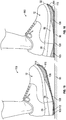
- FIG. 13 when a wearer of the shoe 110 is in a stationary standing position on surface 95 with no shear strain, the viscosity of the fluid in enclosures 105, 106 is at a maximum value and there is no compression of the enclosures, so that the bottom surface of the shoe is flat along most of its length.
- FIG. 15 illustrates an early stance phase of the ground engaging part of a walking step.
- the user rocks forward and the shear strain applied to the part 105 is removed, so that lower surface of the shoe returns to its original conformation against the ground or floor surface 95, as illustrated in FIG. 16 . This is the mid-stance phase of the walking step.
- the user's foot then rocks from the heel to the toe in the late stance phase of FIG. 17 , so that the forward part 106 becomes compressed and conforms to the overlying part of the curved lower surface 64 of rocker piece 58 along with the underlying part of the tread layer, producing more of a rocking motion.
- the rocker development kits described above can be manufactured and sold in various configurations, with or without pre-formed shoe uppers, and allow rocker shoes to be produced in a more systematic and repeatable fashion.
- the rocker shoes of FIGS. 6 , 10 and 13 lead to natural immobilization of the ankle during the single limb stance phase of walking, and are of reduced height relative to conventional rocker shoes of the same rocker radius, since the rocker pieces do not cover the entire plantar surface of the shoe.
- the rocker pieces have an indicator for alignment with the shoe wearer's ankle via a matching indicator on the shoe sole, for better ankle immobilization.
- the rocker pieces incorporate one or more stability inserts for better balance of the wearer when standing still.
- the dimensions (radius and height) of the rocker profile of the rocker kits described above are scaled to the patient's dimensions and can be expressed as a percentage of body height or foot length.
- the rocker radius ranges from 10%-25% of a patient's height (the median radius is 16% of body height), which is approximately 66%-164% of the patient's foot length.
- the height of rocker profile depends on the radius selected as well as the distance between the patient's heel and metatarsophalangeal (MTP) joint. Selecting a larger radius also reduces the build height of the rocker.
- Rocker kits of different rocker radius may be provided for patients of different heights.
Landscapes
- Engineering & Computer Science (AREA)
- Chemical & Material Sciences (AREA)
- Materials Engineering (AREA)
- Health & Medical Sciences (AREA)
- Epidemiology (AREA)
- General Health & Medical Sciences (AREA)
- Public Health (AREA)
- Mechanical Engineering (AREA)
- Footwear And Its Accessory, Manufacturing Method And Apparatuses (AREA)
Claims (14)
- Abrollschuhbaukit (10, 100), Folgendes umfassend:ein Abrollstück (14, 58) aus starrem oder halbstarrem Material, das eine obere Fläche (38), die dazu konfiguriert ist, über einem Hauptteil einer unteren plantaren Fläche der Sohle (26, 28) eines Schuhs (24) befestigt zu werden, die sich von dem Absatz (29) zur Spitze (32) des Schuhs (24) hin erstreckt, und eine untere Fläche (40) von vorbestimmter Abrollform aufweist; eine Zwischenschicht zum Befestigen über der unteren Fläche (40) des Abrollstücks (14, 58); undeine Schicht Laufflächenmaterial (16), die dazu konfiguriert ist, über der unteren Fläche der Zwischenschicht und jedes freiliegenden Abschnitts der plantaren Fläche eines Schuhs (24) befestigt zu werden, an dem das Kit (10) befestigt ist; dadurch gekennzeichnet, dassdie Zwischenschicht eine oder mehrere Kammern umfasst, die ein strukturviskoses Fluid enthalten.
- Kit (10, 100) nach Anspruch 1, ferner einen Schuhschaft (12) umfassend, der eine Sohle (28) mit einer plantaren Fläche aufweist, die einen flachen Flächenabschnitt aufweist, der sich entlang mindestens eines Teils von der Länge der Sohle (26, 28) von dem Absatz (29) zu der Spitze (32) des Schuhschafts hin erstreckt, wobei die obere Fläche (59) des Abrollstücks (14, 58) ebenfalls flach ist.
- Kit (10, 100) nach Anspruch 1, wobei das Abrollstück (14, 58), die Zwischenschicht und die Schicht Laufflächenmaterial (16) dazu konfiguriert sind, an der unteren plantaren Fläche einer Sohle eines linken Schuhschafts befestigt zu werden und ferner ein Abrollstück (14, 58), eine zweite Zwischenschicht und eine zweite Schicht Laufflächenmaterial umfassend, die dazu konfiguriert sind, an der unteren plantaren Fläche einer Sohle eines rechten Schuhschafts befestigt zu werden.
- Kit (10, 100) nach Anspruch 3, ferner den linken Schuhschaft und den rechten Schuhschaft umfassend, wobei die untere plantare Fläche von jeder der Sohlen (26, 28) des linken und rechten Schuhschafts einen flachen Flächenabschnitt aufweist, der sich entlang mindestens eines Teils von der Länge der Sohle (26, 28) von dem Absatz (29) zu der Spitze (32) des linken bzw. rechten Schuhschafts hin erstreckt, wobei die obere Fläche des ersten Abrollstücks bzw. des zweiten Abrollstücks ebenfalls flach ist.
- Kit (10, 100) nach Anspruch 2, wobei mindestens eine Seite der Sohle des Schuhschafts einen ersten Indikator (34, 46) aufweist, der zumindest annähernd an einem Sprunggelenk eines Trägers des Schuhs (24) ausgerichtet ist, und eine entsprechende Seite des Abrollstücks einen entsprechenden zweiten Indikator (34, 46) zum Ausrichten an dem ersten Indikator (34, 46) aufweist, wenn das Abrollstück (14, 58) an der Sohle befestigt ist.
- Kit (10, 100) nach Anspruch 1, wobei die untere Fläche (40) des Abrollstücks gebogen ist und die Zwischenschicht und die Laufflächenschicht dazu konfiguriert sind, sich der Biegung der gebogenen unteren Fläche (40) anzupassen, wenn das Abrollstück (14, 58) und die Zwischenschicht und die Laufflächenschicht zusammengefügt sind.
- Kit (10, 100) nach Anspruch 6, wobei die Biegung der unteren Fläche (40) des Abrollstücks ausgewählt ist, um einen Abrollradius im Bereich von 10 %-25 % der Größe eines Trägers zu bilden oder wobei die untere Fläche (40) des Abrollstücks mindestens eine Kerbe, die sich über die Breite der Fläche (40) erstreckt, und mindestens einen deformierbaren Einsatz aufweist, der zum Befestigen in der Kerbe konfiguriert ist und ein dilatantes Fluid oder ein hochgedämpftes Material enthält, das sich unter statischer Last deformiert, wobei der Einsatz eine gebogene untere Fläche in einem während des Gehens nicht deformierten Zustand aufweist, und eine abgeflachte untere Fläche aufweist, wenn er unter statischer Last deformiert wird, wenn ein Träger steht, wobei ein Bereich der darunterliegenden Lauffläche (16) abgeflacht wird.
- Kit (10, 100) nach Anspruch 1, wobei das strukturviskose Fluid eine maximale Viskosität aufweist, bei der es unter statischen Bedingungen zumindest nicht wesentlich komprimierbar ist, wobei die Zwischenschicht einen flachen unteren Flächenabschnitt aufweist, der sich von dem Absatz (29) aus erstreckt und unter statischen Bedingungen kurz vor der Spitze (32) des Schuhs endet und fortschreitend komprimiert wird, wenn ein Träger des Schuhs geht.
- Kit (10, 100) nach Anspruch 1, wobei die Zwischenschicht eine Polsterschicht (15) umfasst und wobei die untere Fläche (40) des Abrollstücks (14, 58) die obere Fläche (38) an einem vorderen Unterbrechungspunkt (36) trifft und die obere Fläche der Polsterschicht (15) eine Form aufweist, die zu der unteren Fläche (40) des Abrollstücks (14, 58) bis zu dem vorderen Unterbrechungspunkt (36) passt, und eine flache obere Endfläche aufweist, die dazu konfiguriert ist, an der unteren plantaren Fläche von der Sohle (28) des Schuhs vor dem Unterbrechungspunkt (36) des Abrollstücks (14, 58) zu haften.
- Kit (10, 100) nach Anspruch 9, wobei die Zwischenschicht eine Polsterschicht (15) umfasst und wobei die untere Fläche (40) des Abrollstücks (14, 58) und die obere Fläche der Polsterschicht (15) entweder von passender, gebogener Form bis zu der flachen oberen Endfläche oder von passender, eckiger Form bis zu der flachen oberen Endfläche sind, wobei die eckige Form einen flachen Flächenabschnitt, der sich von einem Absatzende hin zu einem Vorderende erstreckt, und einen sich nach oben verjüngenden Abschnitt umfasst, der sich von dem flachen Flächenabschnitt jeweils zu dem vorderen Unterbrechungspunkt (36) und der flachen oberen Endfläche des Abrollstücks (14, 58) und der Polsterschicht (15) erstreckt.
- Kit (10, 100) nach Anspruch 1, ferner eine zweifache Vorspannvorrichtung (18) umfassend, zum Halten eines Paars Schuhe (24), während die Sohlen (26) geschnitten werden, um flache Flächenabschnitte zum Befestigen an einer oberen Fläche (38) eines Abrollstücks (14, 58) zu bilden.
- Abrollschuh (52, 55), der durch Verwenden des Kits (10, 100) nach einem der Ansprüche 1 bis 11 gebaut wird, Folgendes umfassend:einen Schuhschaft (12), der einen Absatz (29), eine Spitze (32) und eine Sohle (26) aufweist;einen Abrollabschnitt mit einer unteren Abrollfläche (40), die sich über mindestens einen Hauptabschnitt der Sohle erstreckt;einen Abrollabschnitt, der ein Abrollstück (14, 58) aus starrem oder halbstarrem Material umfasst, das eine obere Fläche (38), die an der unteren plantaren Fläche des Schuhs und einer unteren Fläche (40) befestigt ist, und eine Zwischenschicht, die über der unteren Fläche (40) des Abrollstücks befestigt ist, und eine Schicht Laufflächenmaterial (16), die über der unteren Fläche der Zwischenschicht und über jedem freiliegenden Abschnitt der plantaren Fläche des Schuhs (24) befestigt ist, aufweist;dadurch gekennzeichnet, dassdie Zwischenschicht eine oder mehrere Kammern umfasst, die ein strukturviskoses Fluid enthalten.
- Abrollschuh (52, 55) nach Anspruch 12, ferner einen oder mehrere Einsätze aus komprimierbarem Material umfassend, die in einer oder mehreren Aussparungen in der unteren Fläche (40) des Abrollstücks (14, 58) montiert sind, wobei sich die Zwischenschicht über die untere Fläche (40) des Abrollstücks und der Einsätze erstreckt.
- Verfahren zum Bau eines Abrollschuhs (52, 55) nach einem der Ansprüche 1-13, Folgendes umfassend:Anbringen einer oberen Fläche (38) eines Abrollstücks (14, 58) aus starrem oder halbstarrem, nicht deformierbarem Material an der unteren Fläche der Sohle (26) eines Schuhschafts, wobei sich ein hinteres Ende des Abrollstücks (14, 58) an dem Absatz (29) des Schuhschafts befindet und das Vorderende von der Spitze (29) des Schuhschafts beabstandet ist;Anbringen einer Zwischenschicht, die aus einem anderen Material besteht als das Abrollstück (14, 58), über einer unteren Fläche (40) des Abrollstücks, wobei die Zwischenschicht eine oder mehrere Kammern umfasst, die ein strukturviskose Fluid enthalten; undAnbringen einer Schicht Laufflächenmaterial (16) über einer unteren Fläche der Zwischenschicht und jedem freiliegenden Abschnitt der Sohle (26) des Schuhs vor dem Abrollstück (14, 58) und der Zwischenschicht.
Applications Claiming Priority (2)
| Application Number | Priority Date | Filing Date | Title |
|---|---|---|---|
| US201562153365P | 2015-04-27 | 2015-04-27 | |
| PCT/US2016/029597 WO2016176351A1 (en) | 2015-04-27 | 2016-04-27 | Rocker shoes, rocker shoe development kit and method |
Publications (3)
| Publication Number | Publication Date |
|---|---|
| EP3288408A1 EP3288408A1 (de) | 2018-03-07 |
| EP3288408A4 EP3288408A4 (de) | 2019-01-02 |
| EP3288408B1 true EP3288408B1 (de) | 2020-06-17 |
Family
ID=57198775
Family Applications (1)
| Application Number | Title | Priority Date | Filing Date |
|---|---|---|---|
| EP16787085.6A Not-in-force EP3288408B1 (de) | 2015-04-27 | 2016-04-27 | Abrollschuhe, abrollschuhentwicklungskit und verfahren |
Country Status (5)
| Country | Link |
|---|---|
| US (2) | US10292452B2 (de) |
| EP (1) | EP3288408B1 (de) |
| AU (1) | AU2016254020B2 (de) |
| CA (1) | CA2983909A1 (de) |
| WO (1) | WO2016176351A1 (de) |
Families Citing this family (13)
| Publication number | Priority date | Publication date | Assignee | Title |
|---|---|---|---|---|
| EP3288408B1 (de) | 2015-04-27 | 2020-06-17 | United States Government as Represented by the Department of Veterans Affairs | Abrollschuhe, abrollschuhentwicklungskit und verfahren |
| US10779611B2 (en) * | 2015-08-27 | 2020-09-22 | Reshod Walking Shoes, Llc | Midsole, sole assembly and footwear for walking and running |
| KR102295998B1 (ko) * | 2017-05-23 | 2021-09-02 | 나이키 이노베이트 씨.브이. | 단계화된 압축 강도를 갖는 돔형 중창 |
| IT201800003863A1 (it) * | 2018-03-22 | 2019-09-22 | Pietro Galifi | Dispositivo per determinare il movimento in spazi virtuali o reali. |
| US12096823B1 (en) * | 2018-11-30 | 2024-09-24 | Under Armour, Inc. | Article of footwear |
| WO2020163531A1 (en) | 2019-02-06 | 2020-08-13 | Fuerst Group, Inc. | Footwear article for walking |
| US12279669B2 (en) | 2019-02-06 | 2025-04-22 | Keen, Inc. | Footwear article for walking |
| US12478127B1 (en) * | 2019-04-26 | 2025-11-25 | Matthew Kirby | Catcher's shoe |
| JPWO2021260920A1 (de) * | 2020-06-26 | 2021-12-30 | ||
| CN115697121B (zh) | 2020-07-13 | 2026-01-06 | 耐克创新有限合伙公司 | 具有用于向前动量的鞋底夹层突起和弧形轮廓的鞋底结构 |
| NL2027067B1 (en) | 2020-12-08 | 2022-07-07 | Univ Groningen | A computer implemented method for selecting a shape of a rocker outsole |
| USD1049599S1 (en) | 2022-09-02 | 2024-11-05 | Mark V. Dentler | Pair of shoe insoles |
| US12557878B2 (en) * | 2023-02-13 | 2026-02-24 | Xelero Technology, LLC | Footwear sole assembly |
Family Cites Families (32)
| Publication number | Priority date | Publication date | Assignee | Title |
|---|---|---|---|---|
| US434678A (en) * | 1890-08-19 | Lewis quigg | ||
| US244083A (en) * | 1881-07-12 | James siallwood | ||
| US693673A (en) * | 1901-11-26 | 1902-02-18 | George C Meakim | Work-support. |
| US1087423A (en) * | 1908-09-29 | 1914-02-17 | Boylston Mfg Co | Treeing-stand. |
| US1463753A (en) * | 1919-06-19 | 1923-07-31 | Sumner Lathey | Shoe-last stand |
| US1467712A (en) * | 1922-02-24 | 1923-09-11 | Sanctis John De | Shoe jack |
| US2046353A (en) * | 1932-07-05 | 1936-07-07 | Theodore F Whitmore | Shoe last |
| US1977157A (en) * | 1933-03-18 | 1934-10-16 | William E Strobel | Reversible last and foot-rest |
| US2048837A (en) * | 1935-04-17 | 1936-07-28 | Edward R Byers | Shoe flexing device |
| US3203050A (en) * | 1963-01-08 | 1965-08-31 | Southern Shoe Machinery Compan | Shoe last structure for the manufacture of plastic soles upon shoe uppers |
| US4348821A (en) * | 1980-06-02 | 1982-09-14 | Daswick Alexander C | Shoe sole structure |
| FI71866C (fi) * | 1985-09-10 | 1987-03-09 | Karhu Titan Oy | Sulkonstruktion foer sportsko. |
| US4794707A (en) | 1986-06-30 | 1989-01-03 | Converse Inc. | Shoe with internal dynamic rocker element |
| US4771768A (en) | 1986-12-16 | 1988-09-20 | United States Manufacturing Company | Controlled motion ankle fracture walker |
| US5592757A (en) * | 1994-03-02 | 1997-01-14 | Jackinsky; Carmen U. | Shoe with walking sole |
| JP2791658B1 (ja) * | 1997-02-25 | 1998-08-27 | 京阪通商株式会社 | 靴の底およびそれを含む靴ならびにサンダル |
| WO1999003368A1 (de) * | 1997-07-17 | 1999-01-28 | Negort Ag | Schuh |
| CN1236710C (zh) * | 1999-08-28 | 2006-01-18 | 尼格特股份公司 | 主动式滚动型步行装置 |
| US7111416B2 (en) * | 2003-04-07 | 2006-09-26 | Gallegos Alvaro Z | Footwear |
| EP1785048A1 (de) * | 2005-11-09 | 2007-05-16 | Arno Schneider | Schuh |
| US20080016724A1 (en) * | 2006-07-20 | 2008-01-24 | Hlavac Harry F | Dynamic sole |
| KR100849600B1 (ko) * | 2008-01-18 | 2008-07-31 | (주)알와이엔코리아 | 연결판 생크가 내장된 마사이워킹용 전문신발의 에어백미드솔 구조 |
| EP2111771A1 (de) * | 2008-04-23 | 2009-10-28 | Tobias Schumacher | Schuh zum abrollenden Gehen |
| US7877897B2 (en) * | 2008-12-16 | 2011-02-01 | Skechers U.S.A., Inc. Ii | Shoe |
| US8316558B2 (en) * | 2008-12-16 | 2012-11-27 | Skechers U.S.A., Inc. Ii | Shoe |
| US20100263233A1 (en) | 2009-04-06 | 2010-10-21 | Northwestern University | Rocker shoes for prescribed ankle motion |
| KR100920630B1 (ko) * | 2009-04-16 | 2009-10-08 | 강형철 | 충격흡수부재의 교체가 가능하도록 된 신발용 밑창 |
| US20100299969A1 (en) * | 2009-05-29 | 2010-12-02 | Liliana Paez | Layered footwear assembly with an arcuate undersurface |
| US7958993B2 (en) * | 2009-09-18 | 2011-06-14 | Nike, Inc. | Footwear customization kit |
| EP2353423A3 (de) | 2010-02-04 | 2013-01-02 | Pikolino's Intercontinental, S.A. | Verbesserte Sohle für Schuhwerk |
| US8595956B2 (en) * | 2011-09-29 | 2013-12-03 | C. & J. Clark International Limited | Footwear with elastic footbed cover and soft foam footbed |
| EP3288408B1 (de) * | 2015-04-27 | 2020-06-17 | United States Government as Represented by the Department of Veterans Affairs | Abrollschuhe, abrollschuhentwicklungskit und verfahren |
-
2016
- 2016-04-27 EP EP16787085.6A patent/EP3288408B1/de not_active Not-in-force
- 2016-04-27 CA CA2983909A patent/CA2983909A1/en not_active Abandoned
- 2016-04-27 WO PCT/US2016/029597 patent/WO2016176351A1/en not_active Ceased
- 2016-04-27 AU AU2016254020A patent/AU2016254020B2/en not_active Ceased
- 2016-04-27 US US15/569,378 patent/US10292452B2/en active Active
-
2019
- 2019-05-14 US US16/411,593 patent/US10779612B2/en active Active
Non-Patent Citations (1)
| Title |
|---|
| None * |
Also Published As
| Publication number | Publication date |
|---|---|
| EP3288408A4 (de) | 2019-01-02 |
| US20180295936A1 (en) | 2018-10-18 |
| AU2016254020B2 (en) | 2020-07-16 |
| US20190261734A1 (en) | 2019-08-29 |
| AU2016254020A1 (en) | 2017-11-16 |
| EP3288408A1 (de) | 2018-03-07 |
| US10292452B2 (en) | 2019-05-21 |
| US10779612B2 (en) | 2020-09-22 |
| CA2983909A1 (en) | 2016-11-03 |
| WO2016176351A1 (en) | 2016-11-03 |
Similar Documents
| Publication | Publication Date | Title |
|---|---|---|
| US10779612B2 (en) | Rocker shoes, rocker shoe development kit and method | |
| US11839563B2 (en) | Orthopedic walking brace having a curved sole | |
| KR101472734B1 (ko) | 자세보정용 맞춤형 아치핏 인솔 | |
| CN113677230A (zh) | 支持自然步态的高跟鞋 | |
| JP2012513246A (ja) | 関節炎痛を緩和するための履物用中敷 | |
| US11564444B2 (en) | Footwear with dynamic arch system | |
| EP3058838A1 (de) | Zwischensohle zur druckdispersion von miittelfuss- und metatarsalknochen und schuh damit | |
| US20180199663A1 (en) | Color matched fashionable shoe insert for open shoes device and method | |
| US20130067764A1 (en) | Integrated medical shoe device | |
| US10667574B2 (en) | Functional orthotic support structure for footwear | |
| CN110167379B (zh) | 高跟鞋的体重负荷结构体 | |
| CN206252570U (zh) | 平衡足压矫正鞋垫 | |
| CN202637209U (zh) | 足部平衡结构 | |
| CN203952588U (zh) | 一种反向楦矫正鞋以及反向鞋楦 | |
| US11786009B2 (en) | Footwear system with integrated orthotics, stabilization features, and a plurality of design features | |
| CN201586103U (zh) | 鞋垫 | |
| WO2012110978A1 (en) | An expandable shoe sole | |
| CN211379850U (zh) | 一种功能鞋底 | |
| WO2016013042A1 (ja) | ヒール及びパンプス用組立式インソール | |
| KR101799947B1 (ko) | 앞 굽이 높은 신발 | |
| HK40065047A (en) | High heeled shoes supporting natural gait | |
| KR20140093872A (ko) | 기능성 신발깔창 및 샌달용 깔창 | |
| CZ2013533A3 (cs) | Obuv se speciální mezipodešví | |
| CZ25838U1 (cs) | Obuv se speciální mezipodešví | |
| CA2954878A1 (en) | Color matched fashionable shoe insert for open shoes device and method |
Legal Events
| Date | Code | Title | Description |
|---|---|---|---|
| STAA | Information on the status of an ep patent application or granted ep patent |
Free format text: STATUS: THE INTERNATIONAL PUBLICATION HAS BEEN MADE |
|
| PUAI | Public reference made under article 153(3) epc to a published international application that has entered the european phase |
Free format text: ORIGINAL CODE: 0009012 |
|
| STAA | Information on the status of an ep patent application or granted ep patent |
Free format text: STATUS: REQUEST FOR EXAMINATION WAS MADE |
|
| 17P | Request for examination filed |
Effective date: 20171031 |
|
| AK | Designated contracting states |
Kind code of ref document: A1 Designated state(s): AL AT BE BG CH CY CZ DE DK EE ES FI FR GB GR HR HU IE IS IT LI LT LU LV MC MK MT NL NO PL PT RO RS SE SI SK SM TR |
|
| AX | Request for extension of the european patent |
Extension state: BA ME |
|
| DAV | Request for validation of the european patent (deleted) | ||
| DAX | Request for extension of the european patent (deleted) | ||
| A4 | Supplementary search report drawn up and despatched |
Effective date: 20181203 |
|
| RIC1 | Information provided on ipc code assigned before grant |
Ipc: A43B 13/00 20060101ALI20181127BHEP Ipc: A43B 7/32 20060101ALI20181127BHEP Ipc: A43B 9/16 20060101ALI20181127BHEP Ipc: A43B 13/14 20060101AFI20181127BHEP Ipc: A43B 3/00 20060101ALI20181127BHEP Ipc: A43B 13/12 20060101ALI20181127BHEP Ipc: A43B 13/16 20060101ALI20181127BHEP |
|
| STAA | Information on the status of an ep patent application or granted ep patent |
Free format text: STATUS: EXAMINATION IS IN PROGRESS |
|
| 17Q | First examination report despatched |
Effective date: 20191001 |
|
| GRAP | Despatch of communication of intention to grant a patent |
Free format text: ORIGINAL CODE: EPIDOSNIGR1 |
|
| STAA | Information on the status of an ep patent application or granted ep patent |
Free format text: STATUS: GRANT OF PATENT IS INTENDED |
|
| INTG | Intention to grant announced |
Effective date: 20200211 |
|
| RIN1 | Information on inventor provided before grant (corrected) |
Inventor name: NICKEL, ERIC Inventor name: HANSEN, ANDREW H. Inventor name: KOEHLER, SARA Inventor name: SCHULTZ, CHARLES |
|
| GRAS | Grant fee paid |
Free format text: ORIGINAL CODE: EPIDOSNIGR3 |
|
| GRAA | (expected) grant |
Free format text: ORIGINAL CODE: 0009210 |
|
| STAA | Information on the status of an ep patent application or granted ep patent |
Free format text: STATUS: THE PATENT HAS BEEN GRANTED |
|
| AK | Designated contracting states |
Kind code of ref document: B1 Designated state(s): AL AT BE BG CH CY CZ DE DK EE ES FI FR GB GR HR HU IE IS IT LI LT LU LV MC MK MT NL NO PL PT RO RS SE SI SK SM TR |
|
| REG | Reference to a national code |
Ref country code: GB Ref legal event code: FG4D |
|
| REG | Reference to a national code |
Ref country code: CH Ref legal event code: EP |
|
| REG | Reference to a national code |
Ref country code: IE Ref legal event code: FG4D |
|
| REG | Reference to a national code |
Ref country code: DE Ref legal event code: R096 Ref document number: 602016038344 Country of ref document: DE |
|
| REG | Reference to a national code |
Ref country code: AT Ref legal event code: REF Ref document number: 1280291 Country of ref document: AT Kind code of ref document: T Effective date: 20200715 |
|
| PG25 | Lapsed in a contracting state [announced via postgrant information from national office to epo] |
Ref country code: GR Free format text: LAPSE BECAUSE OF FAILURE TO SUBMIT A TRANSLATION OF THE DESCRIPTION OR TO PAY THE FEE WITHIN THE PRESCRIBED TIME-LIMIT Effective date: 20200918 Ref country code: NO Free format text: LAPSE BECAUSE OF FAILURE TO SUBMIT A TRANSLATION OF THE DESCRIPTION OR TO PAY THE FEE WITHIN THE PRESCRIBED TIME-LIMIT Effective date: 20200917 Ref country code: FI Free format text: LAPSE BECAUSE OF FAILURE TO SUBMIT A TRANSLATION OF THE DESCRIPTION OR TO PAY THE FEE WITHIN THE PRESCRIBED TIME-LIMIT Effective date: 20200617 Ref country code: SE Free format text: LAPSE BECAUSE OF FAILURE TO SUBMIT A TRANSLATION OF THE DESCRIPTION OR TO PAY THE FEE WITHIN THE PRESCRIBED TIME-LIMIT Effective date: 20200617 Ref country code: LT Free format text: LAPSE BECAUSE OF FAILURE TO SUBMIT A TRANSLATION OF THE DESCRIPTION OR TO PAY THE FEE WITHIN THE PRESCRIBED TIME-LIMIT Effective date: 20200617 |
|
| REG | Reference to a national code |
Ref country code: LT Ref legal event code: MG4D |
|
| REG | Reference to a national code |
Ref country code: NL Ref legal event code: MP Effective date: 20200617 |
|
| PG25 | Lapsed in a contracting state [announced via postgrant information from national office to epo] |
Ref country code: RS Free format text: LAPSE BECAUSE OF FAILURE TO SUBMIT A TRANSLATION OF THE DESCRIPTION OR TO PAY THE FEE WITHIN THE PRESCRIBED TIME-LIMIT Effective date: 20200617 Ref country code: BG Free format text: LAPSE BECAUSE OF FAILURE TO SUBMIT A TRANSLATION OF THE DESCRIPTION OR TO PAY THE FEE WITHIN THE PRESCRIBED TIME-LIMIT Effective date: 20200917 Ref country code: LV Free format text: LAPSE BECAUSE OF FAILURE TO SUBMIT A TRANSLATION OF THE DESCRIPTION OR TO PAY THE FEE WITHIN THE PRESCRIBED TIME-LIMIT Effective date: 20200617 Ref country code: HR Free format text: LAPSE BECAUSE OF FAILURE TO SUBMIT A TRANSLATION OF THE DESCRIPTION OR TO PAY THE FEE WITHIN THE PRESCRIBED TIME-LIMIT Effective date: 20200617 |
|
| REG | Reference to a national code |
Ref country code: AT Ref legal event code: MK05 Ref document number: 1280291 Country of ref document: AT Kind code of ref document: T Effective date: 20200617 |
|
| PG25 | Lapsed in a contracting state [announced via postgrant information from national office to epo] |
Ref country code: NL Free format text: LAPSE BECAUSE OF FAILURE TO SUBMIT A TRANSLATION OF THE DESCRIPTION OR TO PAY THE FEE WITHIN THE PRESCRIBED TIME-LIMIT Effective date: 20200617 Ref country code: AL Free format text: LAPSE BECAUSE OF FAILURE TO SUBMIT A TRANSLATION OF THE DESCRIPTION OR TO PAY THE FEE WITHIN THE PRESCRIBED TIME-LIMIT Effective date: 20200617 |
|
| PG25 | Lapsed in a contracting state [announced via postgrant information from national office to epo] |
Ref country code: AT Free format text: LAPSE BECAUSE OF FAILURE TO SUBMIT A TRANSLATION OF THE DESCRIPTION OR TO PAY THE FEE WITHIN THE PRESCRIBED TIME-LIMIT Effective date: 20200617 Ref country code: SM Free format text: LAPSE BECAUSE OF FAILURE TO SUBMIT A TRANSLATION OF THE DESCRIPTION OR TO PAY THE FEE WITHIN THE PRESCRIBED TIME-LIMIT Effective date: 20200617 Ref country code: EE Free format text: LAPSE BECAUSE OF FAILURE TO SUBMIT A TRANSLATION OF THE DESCRIPTION OR TO PAY THE FEE WITHIN THE PRESCRIBED TIME-LIMIT Effective date: 20200617 Ref country code: RO Free format text: LAPSE BECAUSE OF FAILURE TO SUBMIT A TRANSLATION OF THE DESCRIPTION OR TO PAY THE FEE WITHIN THE PRESCRIBED TIME-LIMIT Effective date: 20200617 Ref country code: IT Free format text: LAPSE BECAUSE OF FAILURE TO SUBMIT A TRANSLATION OF THE DESCRIPTION OR TO PAY THE FEE WITHIN THE PRESCRIBED TIME-LIMIT Effective date: 20200617 Ref country code: CZ Free format text: LAPSE BECAUSE OF FAILURE TO SUBMIT A TRANSLATION OF THE DESCRIPTION OR TO PAY THE FEE WITHIN THE PRESCRIBED TIME-LIMIT Effective date: 20200617 Ref country code: ES Free format text: LAPSE BECAUSE OF FAILURE TO SUBMIT A TRANSLATION OF THE DESCRIPTION OR TO PAY THE FEE WITHIN THE PRESCRIBED TIME-LIMIT Effective date: 20200617 Ref country code: PT Free format text: LAPSE BECAUSE OF FAILURE TO SUBMIT A TRANSLATION OF THE DESCRIPTION OR TO PAY THE FEE WITHIN THE PRESCRIBED TIME-LIMIT Effective date: 20201019 |
|
| PG25 | Lapsed in a contracting state [announced via postgrant information from national office to epo] |
Ref country code: PL Free format text: LAPSE BECAUSE OF FAILURE TO SUBMIT A TRANSLATION OF THE DESCRIPTION OR TO PAY THE FEE WITHIN THE PRESCRIBED TIME-LIMIT Effective date: 20200617 Ref country code: SK Free format text: LAPSE BECAUSE OF FAILURE TO SUBMIT A TRANSLATION OF THE DESCRIPTION OR TO PAY THE FEE WITHIN THE PRESCRIBED TIME-LIMIT Effective date: 20200617 Ref country code: IS Free format text: LAPSE BECAUSE OF FAILURE TO SUBMIT A TRANSLATION OF THE DESCRIPTION OR TO PAY THE FEE WITHIN THE PRESCRIBED TIME-LIMIT Effective date: 20201017 |
|
| REG | Reference to a national code |
Ref country code: DE Ref legal event code: R097 Ref document number: 602016038344 Country of ref document: DE |
|
| PLBE | No opposition filed within time limit |
Free format text: ORIGINAL CODE: 0009261 |
|
| STAA | Information on the status of an ep patent application or granted ep patent |
Free format text: STATUS: NO OPPOSITION FILED WITHIN TIME LIMIT |
|
| PG25 | Lapsed in a contracting state [announced via postgrant information from national office to epo] |
Ref country code: DK Free format text: LAPSE BECAUSE OF FAILURE TO SUBMIT A TRANSLATION OF THE DESCRIPTION OR TO PAY THE FEE WITHIN THE PRESCRIBED TIME-LIMIT Effective date: 20200617 |
|
| 26N | No opposition filed |
Effective date: 20210318 |
|
| PG25 | Lapsed in a contracting state [announced via postgrant information from national office to epo] |
Ref country code: SI Free format text: LAPSE BECAUSE OF FAILURE TO SUBMIT A TRANSLATION OF THE DESCRIPTION OR TO PAY THE FEE WITHIN THE PRESCRIBED TIME-LIMIT Effective date: 20200617 |
|
| PG25 | Lapsed in a contracting state [announced via postgrant information from national office to epo] |
Ref country code: MC Free format text: LAPSE BECAUSE OF FAILURE TO SUBMIT A TRANSLATION OF THE DESCRIPTION OR TO PAY THE FEE WITHIN THE PRESCRIBED TIME-LIMIT Effective date: 20200617 |
|
| PG25 | Lapsed in a contracting state [announced via postgrant information from national office to epo] |
Ref country code: LU Free format text: LAPSE BECAUSE OF NON-PAYMENT OF DUE FEES Effective date: 20210427 |
|
| REG | Reference to a national code |
Ref country code: BE Ref legal event code: MM Effective date: 20210430 |
|
| PG25 | Lapsed in a contracting state [announced via postgrant information from national office to epo] |
Ref country code: CH Free format text: LAPSE BECAUSE OF NON-PAYMENT OF DUE FEES Effective date: 20210430 Ref country code: LI Free format text: LAPSE BECAUSE OF NON-PAYMENT OF DUE FEES Effective date: 20210430 |
|
| PG25 | Lapsed in a contracting state [announced via postgrant information from national office to epo] |
Ref country code: IE Free format text: LAPSE BECAUSE OF NON-PAYMENT OF DUE FEES Effective date: 20210427 |
|
| PG25 | Lapsed in a contracting state [announced via postgrant information from national office to epo] |
Ref country code: IS Free format text: LAPSE BECAUSE OF FAILURE TO SUBMIT A TRANSLATION OF THE DESCRIPTION OR TO PAY THE FEE WITHIN THE PRESCRIBED TIME-LIMIT Effective date: 20201017 |
|
| PG25 | Lapsed in a contracting state [announced via postgrant information from national office to epo] |
Ref country code: BE Free format text: LAPSE BECAUSE OF NON-PAYMENT OF DUE FEES Effective date: 20210430 |
|
| PG25 | Lapsed in a contracting state [announced via postgrant information from national office to epo] |
Ref country code: HU Free format text: LAPSE BECAUSE OF FAILURE TO SUBMIT A TRANSLATION OF THE DESCRIPTION OR TO PAY THE FEE WITHIN THE PRESCRIBED TIME-LIMIT; INVALID AB INITIO Effective date: 20160427 |
|
| P01 | Opt-out of the competence of the unified patent court (upc) registered |
Effective date: 20230523 |
|
| PG25 | Lapsed in a contracting state [announced via postgrant information from national office to epo] |
Ref country code: CY Free format text: LAPSE BECAUSE OF FAILURE TO SUBMIT A TRANSLATION OF THE DESCRIPTION OR TO PAY THE FEE WITHIN THE PRESCRIBED TIME-LIMIT Effective date: 20200617 |
|
| PG25 | Lapsed in a contracting state [announced via postgrant information from national office to epo] |
Ref country code: MK Free format text: LAPSE BECAUSE OF FAILURE TO SUBMIT A TRANSLATION OF THE DESCRIPTION OR TO PAY THE FEE WITHIN THE PRESCRIBED TIME-LIMIT Effective date: 20200617 |
|
| PGFP | Annual fee paid to national office [announced via postgrant information from national office to epo] |
Ref country code: FR Payment date: 20240326 Year of fee payment: 9 |
|
| PGFP | Annual fee paid to national office [announced via postgrant information from national office to epo] |
Ref country code: GB Payment date: 20240411 Year of fee payment: 9 |
|
| PGFP | Annual fee paid to national office [announced via postgrant information from national office to epo] |
Ref country code: DE Payment date: 20240326 Year of fee payment: 9 |
|
| PG25 | Lapsed in a contracting state [announced via postgrant information from national office to epo] |
Ref country code: MT Free format text: LAPSE BECAUSE OF FAILURE TO SUBMIT A TRANSLATION OF THE DESCRIPTION OR TO PAY THE FEE WITHIN THE PRESCRIBED TIME-LIMIT Effective date: 20200617 |
|
| REG | Reference to a national code |
Ref country code: DE Ref legal event code: R119 Ref document number: 602016038344 Country of ref document: DE |
|
| PG25 | Lapsed in a contracting state [announced via postgrant information from national office to epo] |
Ref country code: TR Free format text: LAPSE BECAUSE OF FAILURE TO SUBMIT A TRANSLATION OF THE DESCRIPTION OR TO PAY THE FEE WITHIN THE PRESCRIBED TIME-LIMIT Effective date: 20200617 |
|
| GBPC | Gb: european patent ceased through non-payment of renewal fee |
Effective date: 20250427 |
|
| PG25 | Lapsed in a contracting state [announced via postgrant information from national office to epo] |
Ref country code: DE Free format text: LAPSE BECAUSE OF NON-PAYMENT OF DUE FEES Effective date: 20251104 |
|
| PG25 | Lapsed in a contracting state [announced via postgrant information from national office to epo] |
Ref country code: GB Free format text: LAPSE BECAUSE OF NON-PAYMENT OF DUE FEES Effective date: 20250427 |
|
| PG25 | Lapsed in a contracting state [announced via postgrant information from national office to epo] |
Ref country code: FR Free format text: LAPSE BECAUSE OF NON-PAYMENT OF DUE FEES Effective date: 20250430 |